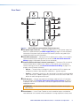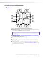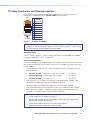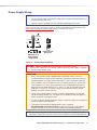
1
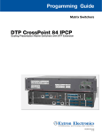
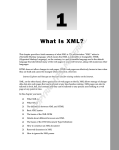
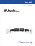
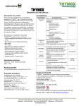
User Guide
HDMI Transmitters
DTP T HWP 232/332 D
DTP T UWP 232/332 D
HDMI Twisted Pair Extender Transmitters
68-2547-01 Rev. A
03 14
Safety Instructions
Safety Instructions • English
WARNING: This symbol,
, when used on the product, is intended to
alert the user of the presence of uninsulated dangerous voltage within the
product’s enclosure that may present a risk of electric shock.
ATTENTION: This symbol,
, when used on the product, is intended
to alert the user of important operating and maintenance (servicing)
instructions in the literature provided with the equipment.
For information on safety guidelines, regulatory compliances, EMI/EMF
compatibility, accessibility, and related topics, see the Extron Safety and
Regulatory Compliance Guide, part number 68-290-01, on the Extron website,
www.extron.com.
Instructions de sécurité • Français
AVERTISSEMENT: Ce pictogramme,
, lorsqu’il est utilisé sur le
produit, signale à l’utilisateur la présence à l’intérieur du boîtier du produit
d’une tension électrique dangereuse susceptible de provoquer un choc
électrique.
ATTENTION: Ce pictogramme,
, lorsqu’il est utilisé sur le produit, signale
à l’utilisateur des instructions d’utilisation ou de maintenance importantes
qui se trouvent dans la documentation fournie avec le matériel.
Pour en savoir plus sur les règles de sécurité, la conformité à la réglementation,
la compatibilité EMI/EMF, l’accessibilité, et autres sujets connexes, lisez les
informations de sécurité et de conformité Extron, réf. 68-290-01, sur le site
Extron, www.extron.com.
Sicherheitsanweisungen • Deutsch
WARNUNG: Dieses Symbol
auf dem Produkt soll den Benutzer darauf
aufmerksam machen, dass im Inneren des Gehäuses dieses Produktes
gefährliche Spannungen herrschen, die nicht isoliert sind und die einen
elektrischen Schlag verursachen können.
Инструкция по технике безопасности • Русский
ПРЕДУПРЕЖДЕНИЕ:
Weitere Informationen über die Sicherheitsrichtlinien, Produkthandhabung,
EMI/EMF-Kompatibilität, Zugänglichkeit und verwandte Themen finden Sie in
den Extron-Richtlinien für Sicherheit und Handhabung (Artikelnummer
68-290-01) auf der Extron-Website, www.extron.com.
Instrucciones de seguridad • Español
ADVERTENCIA: Este símbolo,
, cuando se utiliza en el producto,
avisa al usuario de la presencia de voltaje peligroso sin aislar dentro del
producto, lo que puede representar un riesgo de descarga eléctrica.
ATENCIÓN: Este símbolo,
, cuando se utiliza en el producto, avisa
al usuario de la presencia de importantes instrucciones de uso y
mantenimiento recogidas en la documentación proporcionada con el
equipo.
Para obtener información sobre directrices de seguridad, cumplimiento
de normativas, compatibilidad electromagnética, accesibilidad y temas
relacionados, consulte la Guía de cumplimiento de normativas y seguridad de
Extron, referencia 68-290-01, en el sitio Web de Extron, www.extron.com.
, если указан на продукте,
внутри корпуса продукта, которое может привести к поражению электрическим
током.
ВНИМАНИЕ: Данный символ,
, если указан на продукте,
предупреждает пользователя о наличии важных инструкций
по эксплуатации и обслуживанию в руководстве,
прилагаемом к данному оборудованию.
Для получения информации о правилах техники безопасности,
соблюдении нормативных требований, электромагнитной
совместимости (ЭМП/ЭДС), возможности доступа и других
вопросах см. руководство по безопасности и соблюдению
нормативных требований Extron на сайте Extron: www.extron.com,
номер по каталогу - 68-290-01.
Chinese Simplified(简体中文)
警告:
产品上的这个标志意在警告用户该产品机壳内有暴露的危险 电压,有触电危险。
注 意:
产品上的这个标志意在 提示用户设备随附的用户手册中有
重要的操作和维护(维修)说明。
关于我们产品的安全指南、遵循的规范、EMI/EMF 的兼容性、无障碍
使用的特性等相关内容,敬请访问 Extron 网站 www.extron.com,参见
Extron 安全规范指南,产品编号 68-290-01。
Chinese Traditional(
警告:
VORSICHT: Dieses Symbol
auf dem Produkt soll dem Benutzer in der
im Lieferumfang enthaltenen Dokumentation besonders wichtige Hinweise
zur Bedienung und Wartung (Instandhaltung) geben.
Данный символ,
предупреждает пользователя о наличии неизолированного опасного напряжения
)
若產品上使用此符號,是為了提醒使用者,產品機殼內存在著
可能會導致觸電之風險的未絕緣危險電壓。
注意
若產品上使用此符號,是為了提醒使用者。
有關安全性指導方針、法規遵守、EMI/EMF 相容性、存取範圍和相關主題的詳
細資訊,請瀏覽 Extron 網站:www.extron.com,然後參閱《Extron 安全性與
法規遵守手冊》,準則編號 68-290-01。
Japanese
警告: この記号
が製品上に表示されている場合は、筐体内に絶縁されて
いない高電圧が流れ、感電の危険があることを示しています。
注意: この記号
が製品上に表示されている場合は、本機の取扱説明書に 記載されてい
る重要な操作と保守(整備)の指示についてユーザーの 注意を喚起するものです。
安全上のご注意、法規厳守、EMI/EMF適合性、その他の関連項目に
ついては、エクストロンのウェブサイト www.extron.com より『Extron Safety
and Regulatory Compliance Guide』(P/N 68-290-01) をご覧ください。
Korean
경고: 이 기호
가 제품에 사용될 경우, 제품의 인클로저 내에 있는 접지되지 않은 위험한
전류로 인해 사용자가 감전될 위험이 있음을 경고합니다.
주의:
이 기호
가 제품에 사용될 경우, 장비와 함께 제공된 책자에 나와 있는 주요 운영 및
유지보수(정비) 지침을 경고합니다.
안전 가이드라인, 규제 준수, EMI/EMF 호환성, 접근성, 그리고 관련 항목에
대한 자세한 내용은 Extron 웹 사이트(www.extron.com)의 Extron 안전 및
규제 준수 안내서, 68-290-01 조항을 참조하십시오.
FCC Class A Notice
This equipment has been tested and found to comply with the limits for a Class A digital
device, pursuant to part 15 of the FCC rules. The Class A limits provide reasonable
protection against harmful interference when the equipment is operated in a commercial
environment. This equipment generates, uses, and can radiate radio frequency energy
and, if not installed and used in accordance with the instruction guide, may cause harmful
interference to radio communications. Operation of this equipment in a residential area is
likely to cause interference. This interference must be corrected at the expense of the user.
ATTENTION: The Twisted Pair Extension technology works with shielded twisted pair
(STP) cables only. To ensure FCC Class A and CE compliance, STP cables and STP
connectors are also required.
For more information on safety guidelines, regulatory compliances, EMI/EMF compatibility,
accessibility, and related topics, see the “Extron Safety and Regulatory Compliance Guide”
on the Extron website.
Copyright
© 2014 Extron Electronics. All rights reserved.
Trademarks
All trademarks mentioned in this guide are the properties of their respective owners.
The following registered trademarks®, registered service marks(SM), and trademarks(TM) are the property of
RGB Systems, Inc. or Extron Electronics:
Registered Trademarks (®)
AVTrac, Cable Cubby, CrossPoint, eBUS, EDID Manager, EDID Minder, Extron, Flat Field, GlobalViewer, Hideaway, Inline, IP Intercom,
IP Link, Key Minder, LockIt, MediaLink, PlenumVault, PoleVault, PowerCage, PURE3, Quantum, SoundField, SpeedMount, SpeedSwitch,
System INTEGRATOR, TeamWork, TouchLink, V‑Lock, VersaTools, VN‑Matrix, VoiceLift, WallVault, WindoWall, XTP, and XTP Systems
Registered Service Mark (SM) : S3 Service Support Solutions
Trademarks (™)
AAP, AFL (Accu‑Rate Frame Lock), ADSP (Advanced Digital Sync Processing), Auto‑Image, CDRS (Class D Ripple Suppression), DDSP (Digital
Display Sync Processing), DMI (Dynamic Motion Interpolation), Driver Configurator, DSP Configurator, DSVP (Digital Sync Validation Processing),
FastBite, FOXBOX, IP Intercom HelpDesk, MAAP, MicroDigital, ProDSP, QS-FPC (QuickSwitch Front Panel Controller), Scope‑Trigger, SIS,
Simple Instruction Set, Skew‑Free, SpeedNav, Triple‑Action Switching, XTRA, ZipCaddy, ZipClip
Conventions Used in this Guide
Notifications
The following notifications are used in this guide:
CAUTION: A caution indicates a situation that may result in minor injury.
ATTENTION: Attention indicates a situation that may damage or destroy the product or
associated equipment.
NOTE: A note draws attention to important information.
Software Commands
Commands are written in the fonts shown here:
^AR Merge Scene,,Op1 scene 1,1 ^B 51 ^W^C
[01] R 0004 00300 00400 00800 00600 [02] 35 [17] [03]
E X! *X1&* X2)* X2#* X2! CE}
NOTE: For commands and examples of computer or device responses mentioned
in this guide, the character “0” is used for the number zero and “O” is the capital
letter “o.”
Computer responses and directory paths that do not have variables are written in the font
shown here:
Reply from 208.132.180.48: bytes=32 times=2ms TTL=32
C:\Program Files\Extron
Variables are written in slanted form as shown here:
ping xxx.xxx.xxx.xxx —t
SOH R Data STX Command ETB ETX
Selectable items, such as menu names, menu options, buttons, tabs, and field names are
written in the font shown here:
From the File menu, select New.
Click the OK button.
Specifications Availability
Product specifications are available on the Extron website, www.extron.com.
Contents
Introduction............................................................ 1
Remote Control.................................................... 16
About this Guide.................................................. 1
About the DTP T HWP D and DTP T UWP D
Extenders........................................................... 1
Twisted Pair Cable Advantages........................ 2
Transmission Distance..................................... 2
Features.............................................................. 3
Contact Closure Control.................................... 16
Simple Instruction Set Control........................... 17
Host-to-Extender Communications................ 17
Extender-Initiated Messages.......................... 17
Error Responses............................................ 17
Timeout......................................................... 17
Using the Command and Response Table..... 18
Command and Response Table for SIS
Commands.................................................. 20
Installation and Operation................................... 4
Mounting the Transmitter..................................... 4
UL and Safety Guidelines................................. 4
Site Preparation and Wall Box Installation........ 5
Mud Ring Installation....................................... 6
Final Installation............................................... 7
DTP T HWP 232 and 332 D Connections............ 8
Front Panel...................................................... 8
Rear Panel....................................................... 9
DTP T UWP 232 and 332 D Connections.......... 10
Front Panel.................................................... 10
Rear Panel..................................................... 11
TP Cable Termination and
Recommendations........................................... 12
Power Supply Wiring......................................... 13
RS-232 and IR Connector Wiring...................... 14
Remote RS-232 and Contact Closure
Connector.................................................... 14
IR Control Connector..................................... 14
Over DTP RS-232 Connector........................ 14
Operation.......................................................... 15
Transmitter LEDs........................................... 15
System Operation.......................................... 15
Reference Information....................................... 24
Decora Template Dimensions............................ 24
DTP T HWP/UWP 232/332 D Transmitters • Contents
v
Introduction
•
About this Guide
•
About the DTP T HWP D and DTP T UWP D Extenders
•
Features
About this Guide
This guide provides instructions for experienced, professional installers to install, operate,
and configure the Extron DTP T HWP D and DTP T UWP D family of High-Definition
Multimedia Interface (HDMI®) and VGA Extenders.
Terms Used in this Guide
The terms “extender” and “transmitter” are used interchangeably in this guide to refer to all
of the DTP T HWP D and DTP T UWP D models.
About the DTP T HWP D and DTP T UWP D Extenders
The Extron DTP T HWP D and DTP T UWP D extenders are a family of HDMI and
VGA transmitters (see figure 1) that are housed in enclosures that can be mounted in
Underwriters Laboratories (UL®) standard wall boxes with Decora®-style faceplates. Paired
with a compatible DTP 230 or 330 receiver, they extend the usable distance of HDMI digital
video, VGA analog video (UWP models only), and RS-232 or IR control signals over one
shielded twisted pair (STP) cable. The extenders also route audio.
INPUTS
OUTPUTS
INPUTS
1 2 3 4 5 6 7 8
MENU
SIGNAL
1
CONFIG
2
3
4
5
6
7
8
A
B
C
HDCP
VOLUME
ENTER
Extron
IN1608
SCALING PRESENTATION SWITCHER
IN1608 SA
AMPLIFIED OUTPUT
2x25W(8Ω)/2x50W(4Ω)
INPUTS
AUDIO INPUTS
OUTPUTS
L
OUTPUTS
R
OVER DTP
RS-232
1
5
3
7
2
LINK
HDMI
HDMI
4
OVER DTP
RS-232
6
L
IR
Tx Rx G Tx Rx
SIG
CONFIGURABLE
100-240V ~ -- A MAX
C
8
SIG
LINK
IR
OVER DTP
RS-232
1
R
L
3
R
L
5
R
1
2
CLASS 2 WIRING
REMOTE
A
SIG
+48V
LINK
HDMI
IR
B
L
2
R
L
4
R
L
6
R
MIC/LINE
2
LAN
VARIABLE
L
R
RESET
RS-232
+48V
DTP IN
Tx Rx G Tx Rx
DTP IN
Tx Rx G Tx Rx
Tx Rx G
DTP OUT
Ethernet
50/60 Hz
IN1608
AUTO SW
AUDIO IN
HDCP
1
AUDIO IN
VGA IN
HDMI IN
XTP DTP 24 Cable
CONFIG
IR OUT
G
IPCP 505
230 '
S
COM
RTS
SWITCHED
12VDC
R
1
2
LIMIT
3
4
OVER
CTS
TX
IR/S
RELAY
FLEX
I/O
2
3
4
1
2
3
4
1
2
ACT LIMIT
5
6
7
8
5
6
7
8
3
4
OVER
2
3
4
5
6
7
8
LINK
ACT
TLP 1000TV
IPCP 505
Extron
DTP T UWP 232 D Tx
Network
IR
RX
1
100
eBUS
1
TX
RX
Transmitter
XTP DTP 24 Cable
230 '
AUTO SW
AUDIO IN
HDMI IN
HDCP
1
2
AUDIO IN
HDMI IN
CONFIG
IR OUT
XTP DTP 24 Cable
G
S
SIG
LINK
POWER
12V
0.7A MAX
OUTPUTS
L
AUDIO
R
DTP IN
DTP HDMI 230 Rx
HDMI
230 '
Projector
Extron
DTP T HWP 232 D Tx
Transmitter
A Typical DTP T HWP 232 D and DTP T UWP 232 D Application
Figure 1.
A Typical Transmitter and Receiver Application
DTP T HWP/UWP 232/332 D Transmitters • Introduction
1
DTP T HWP D and DTP T UWP D systems consist of a transmitter (Tx) and a receiver
(Rx). The transmitters and corresponding compatible receivers are sold separately. Each
purchased transmitter is shipped with a single external desktop 12 VDC power supply that
accepts 100 to 240 VAC, 50-60 Hz input. A single power supply connected to either the
transmitter or a compatible receiver can power both units through the twisted pair cable that
links the units.
Twisted Pair Cable Advantages
Twisted pair cable is much smaller, lighter, more flexible, and less expensive than coaxial
or HDMI cable. These transmitter and receiver twisted pair (TP) products make cable runs
simpler and less cumbersome. Termination of the cable with RJ-45 connectors is simple,
quick, and economical (see TP Cable Termination and Recommendations on page 12
for more information).
NOTE:Do not use Extron UTP23SF-4 Enhanced Skew-Free AV UTP cable or STP201
cable to link the transmitter and receiver. The DTP T HWP and UWP 232 and 332 do
not work properly with these cables.
Control communications
The RS-232 or infrared (IR) communications are pass-through only. The transmitter and
receiver do not generate or respond to these signals.
Transmission Distance
The maximum transmission distance is determined by the resolution of the signal and the
twisted pair cable, graphics card, and display used in the system.
•
DTP T HWP and UWP 232 D transmitters can transmit 720p, 1080i or 1080p HDTV
video signals up to 230 feet (70 m) over STP cable.
•
DTP T HWP and UWP 332 D transmitters can transmit 720p, 1080i or 1080p HDTV
video signals up to 330 feet (100 m) over STP cable.
DTP T HWP/UWP 232/332 D Transmitters • Introduction
2
Features
Transmits single link HDMI-D signals over one STP cable — Twisted pair cables
provide an economical, easily installed cable solution.
Transmits single link HDMI-D and VGA signals over one STP cable (UWP models)
— Twisted pair cables provide an economical, easily installed cable solution.
Supports DDC and HDCP transmission — The transmitters fully support long distance
transmission of the DDC and HDCP signals.
Control communications pass-through — Bidirectional RS-232 or IR control signals
can be transmitted alongside the HDMI signal, so that the remote display can be controlled
without the need for additional cabling.
Audio routing — The transmitters also route unbalanced stereo audio.
Wall-mountable enclosures
External 100 VAC to 240 VAC, 50-60 Hz, international power supply — Included with
transmitters.
Remote powering of the transmitter or receiver — Only one power supply is necessary
to power both devices.
DTP T HWP/UWP 232/332 D Transmitters • Introduction
3
Installation and
Operation
This section describes the installation and the operation of the extenders, including:
•
Mounting the Transmitter
•
DTP T HWP 232 and 332 D Connections
•
DTP T UWP 232 and 332 D Connections
•
TP Cable Termination and Recommendations
•
Power Supply Wiring
•
RS-232 and IR Connector Wiring
•
Operation
Mounting the Transmitter
ATTENTION:
• Installation and service must be performed by authorized personnel.
• The installation must conform to national and local building, electrical, and safety
codes and to the size requirements of the wall plate.
The transmitters can be installed in a two-gang electrical wall box, or with a mud ring, with a
Decora wall plate cover (supplied).
UL and Safety Guidelines
The following UL guidelines pertain to the installation of the Decora transmitters into a wall
or furniture.
•
These units are not to be connected to a centralized DC power source or used beyond
their rated voltage range.
•
These units must be installed in UL Listed wall boxes.
•
These units must be installed with conduit in accordance with National Electrical Code.
DTP T HWP/UWP 232/332 D Transmitters • Installation and Operation
4
Site Preparation and Wall Box Installation
Choose a location that allows cable runs without interference. Allow enough depth for both
the wall box and the cables. Install the cables into the wall, furniture, or conduits before
installing the wall plate.
NOTE: The extender units are very deep and have connectors on the back side. Extron
recommends a 2-gang wall box which has a depth of at least 3.0 inches (7.6 cm) to
accommodate the connectors and cables.
To install a new wall box, perform steps 1 through 9. If a suitable wall box is already
installed, perform steps 6 through 9 on the next page. UL Listed wall boxes are
recommended.
1. If a wall box is not available to use for a template, use the Decora Template
Dimensions on page 24 to create a template. If installing directly into furniture, cut out
the center portion of the template.
2. Place the wall box (or the full size template) against the installation surface, and mark
the opening guidelines.
3. Cut out the material from the marked area.
4. Insert the wall box into the opening. The rear connectors on the box or wall plate should
fit easily into the opening. Enlarge or smooth the edges of the opening if needed.
5. Secure the wall box with nails or screws, leaving the front edge flush with the outer wall
or furniture surface (see figure 2).
NOTES:
• If attaching the wall box to wood, use four #8 or #10 screws or 10-penny
nails. A minimum of 0.5 inch (1.3 cm) of screw thread must penetrate the
wood.
• If attaching the wall box to metal studs or furniture, use four #8 or #10
self-tapping sheet metal screws or machine bolts with matching nuts.
Wall Stud
Screws or
Nails
Wall opening is
flush with edge of box.
Cable
Clamp
SW
TO
AU
CP
HD
1
DIO
DIO
IN
AU
MI
HD
IN
IN
AU
MI
HD
IN
IG
NF
CO
T
IR
OU
S
G
Signal Output
Cable
Extron
DTP HWP 232 D
Decora Faceplate
Figure 2.
Installing the Wall Box and Mounting the Unit
DTP T HWP/UWP 232/332 D Transmitters • Installation and Operation
5
6. Feed the twisted pair cables and, if applicable, the power cables through the opening
and through the wall box punch-out holes, securing them with cable clamps to provide
strain relief.
NOTES:
• In order to fit in the wall box, the twisted pair cables and RJ-45 connectors
should not have a boot installed.
• One power supply can power both the transmitter and the receiver, so only
one unit needs a power supply (see Power Supply Wiring on page 13).
7. Trim back and insulate exposed cable shields with heat shrink to reduce the chance of
short circuits.
To prevent short circuits, the outer foil shield can be cut back to the point where the
cable exits the cable clamp.
8. Connect the cables to the rear of the unit.
9. Connect front panel devices (see “Front Panel” on pages 8 and 10 for connector
details), restore the power supply, and test the transmitter and receiver system. Make
any cabling adjustments before final installation, as the cables will be inaccessible
afterwards.
Mud Ring Installation
1. Using the mud ring as a guide, mark the edges and cut out the material within the
marked area.
2. Insert the mud ring into the opening, rotate and secure the locking arms with the
supplied screws shown in figure 3.
3. Follow steps 6 through 9 of “Site preparation and wall box installation” above, and
Final Installation on the next page.
Wall
Wall Mounting
Mudring
Figure 3.
Installing the Mud Ring
DTP T HWP/UWP 232/332 D Transmitters • Installation and Operation
6
Final Installation
After testing and making any adjustments, do the following:
1. At the power outlet, unplug the power supply.
NOTE: One power supply can power both the transmitter and the receiver (see
Power Supply Wiring on page 13).
2. Mount the transmitter into the wall box or mud ring and attach the supplied Decora
faceplate to the unit (see figure 2 on page 5).
3. At the power outlet, reconnect the power supply. This powers up both units.
DTP T HWP/UWP 232/332 D Transmitters • Installation and Operation
7
DTP T HWP 232 and 332 D Connections
Front Panel
AUTO SW
AUDIO IN
A
HDMI IN
HDCP
1
2
AUDIO IN
A
A
B
B
C
E
HDMI IN
B
CONFIG
IR OUT
D
S
G
Extron
Figure 4.
DTP
HWP
D Connectors
DTP T HWP
232Tand
332 232/332
D Front Panel
Front
Panel an unbalanced stereo audio source to this 3.5 mm
A Audio input connector
— Connect
mini stereo jack. Figure 5 shows how to wire the audio plug.
Tip
Left (+)
Ring
Right (-)
Sleeve ( )
Figure 5.
Audio Input Connector Wiring
NOTE: The extenders do NOT embed analog audio onto the HDMI signal. This
analog audio signal is transmitted simultaneously with audio embedded within the
HDMI signal.
B HDMI input connector — Connect an HDMI cable between this port and the HDMI
output port of the digital video source.
C Mini USB port — Connect a male USB mini-B cable to this port for SIS configuration
and firmware updates.
D IR output connector — Connect an IR device to this 2-pole, 3.5 mm captive screw
pass-through connector for IR control (see RS-232 and IR Connector Wiring on page
14 to properly wire the IR connector).
DTP T HWP/UWP 232/332 D Transmitters • Installation and Operation
8
Rear Panel
POWER
12V
0.9 A MAX
Tx Rx G
OVER
DTP
C
DTP OUT
SIG
LINK
A/S
Figure 6.
REMOTE
RS-232 CONTACT
Tx Rx
G 1 2
E
+–
R
A
B
D
DTP
T HWP
232 and 332 D232/332
Rear Panel
DTP
T HWP/UWP
D Connectors
Panel — Plug the included external 12 VDC power supply into
A DC powerRear
input connector
either this 2-pole connector (see Power supply wiring on page 13 to wire the power
connector) or the power input connector on the receiver (see the user guide of your
respective receiver for more information).
B Over DTP control port — Connect an RS-232 device to this 3-pole, 3.5 mm captive
screw connector for pass-through RS-232 control (see RS-232 and IR Connector
Wiring on page 14 to properly wire the RS-232 connector).
C Remote (RS-232 and contact closure) control port — Connect an RS-232 device,
contact closure device, or both to this 5-pole, 3.5 mm captive screw connector to
control switching on the unit (see RS-232 and IR Connector Wiring on page 14 to
properly wire the Remote connector).
•
RS-232 — To control the unit through this port, connect an RS-232 device and
configure it as follows: 9600 baud rate, 8 data bits, 1 stop bit, no parity.
•
Contact — Momentarily short pins 1 or 2 to ground (G) to select the corresponding
input. Connect pins 1 and 2 to ground (G) to set the unit to auto switch mode. The
device will select the highest active input.
D DTP Out port — Connect one end of the twisted pair cable to the RJ-45 connector
on the transmitter (see TP Cable Termination and Recommendations on page 12
to properly wire the RJ-45 connectors). Connect the opposite end of the cable to the
appropriate receiver.
ATTENTION: Do not connect this device to a telecommunications or computer
data network.
E Reset button — Use an Extron Tweeker or small screwdriver to press and hold the
recessed button for 6 seconds while the extender is running to perform a factory reset.
DTP T HWP/UWP 232/332 D Transmitters • Installation and Operation
9
DTP T UWP 232 and 332 D Connections
Front Panel
AUTO SW
AUDIO IN
A
A
B
B
AUDIO IN
AUDIO IN
VGA IN
HDMI IN
HDMI IN
332 D
HDCP
1
A
C
CONFIG
IR OUT
C
E
S
G
D
Extron
Figure 7.
T UWP
D Connectors
DTP T UWPDTP
232 and
332 D232/332
Front Panel
Front
A Audio input connector
— Panel
Connect an unbalanced stereo audio source to this 3.5 mm
mini stereo jack (see figure 5 on page 8 for wiring details).
NOTE: The extenders do NOT embed analog audio onto the HDMI signal. This
analog audio signal is transmitted simultaneously with audio embedded within the
HDMI signal.
B HDMI input connector — Connect an HDMI cable between this port and the HDMI
output port of the digital video source.
C VGA input connector — Connect a VGA cable between this port and the output port
of the video source.
D Mini USB port — Connect a male USB mini-B cable to this port for SIS configuration
and firmware updates.
E IR output connector — Connect an IR device to this 2-pole, 3.5 mm captive screw
pass-through connector for IR control (see RS-232 and IR Connector Wiring on page
14 to properly wire the IR connector).
DTP T HWP/UWP 232/332 D Transmitters • Installation and Operation
10
Rear Panel
POWER
12V
0.9 A MAX
Tx Rx G
OVER
DTP
C
DTP OUT
SIG
LINK
A/S
Figure 8.
REMOTE
RS-232 CONTACT
Tx Rx
G 1 2
E
+–
R
A
B
D
DTP
T UWP
232 and 332 D232/332
Rear Panel
DTP
T HWP/UWP
D Connectors
Panel — Plug the included external 12 VDC power supply into
A DC powerRear
input connector
either this 2-pole connector (see Power supply wiring on page 13 to wire the power
connector) or the power input connector on the receiver (see the User Guide of your
respective receiver for more information).
B Over DTP control port — Connect an RS-232 device to this 3-pole, 3.5 mm captive
screw connector for pass-through RS-232 control (see RS-232 and IR Connector
Wiring on page 14 to properly wire the RS-232 connector).
C Remote (RS-232 and contact closure) control port — Connect an RS-232 device,
contact closure device, or both to this 5-pole, 3.5 mm captive screw connector to
control switching on the unit (see RS-232 and IR Connector Wiring on page 14 to
properly wire the Remote connector).
•
RS-232 — To control the unit through this port, connect an RS-232 device and
configure it as follows: 9600 baud rate, 8 data bits, 1 stop bit, no parity.
•
Contact — Momentarily short pins 1 or 2 to ground (G) to select the corresponding
input. Connect pins 1 and 2 to ground (G) to set the unit to auto switch mode. The
device will select the highest active input.
D DTP Out port — Connect one end of the twisted pair cable to the RJ-45 connector
on the transmitter (see TP Cable Termination and Recommendations on page 12
to properly wire the RJ-45 connectors). Connect the opposite end of the cable to the
appropriate receiver.
ATTENTION: Do not connect this device to a telecommunications or computer
data network.
E Reset button — Use an Extron Tweeker or small screwdriver to press and hold the
recessed button for 6 seconds while the extender is running to perform a factory reset.
DTP T HWP/UWP 232/332 D Transmitters • Installation and Operation
11
TP Cable Termination and Recommendations
Figure 9 details the recommended termination of both ends of TP cables with RJ-45
connectors in accordance with the TIA/EIA-T568B wiring standard.
Pins:
12345678
TIA/EIA
T568-B
Pin Wire color
1 White-orange
TP Wires
Figure 9.
2
Orange
3
White-green
4
Blue
5
6
White-blue
Green
7
White-brown
8
Brown
TP Cable Termination
NOTE: Do not use Extron UTP23SF-4 Enhanced Skew-Free AV UTP cable or STP201
cable to link the transmitter and receiver. The DTP T HWP D and DTP T UWP D family
of transmitters do not work properly with these cables.
Supported cables —
The DTP T HWP D and DTP T UWP D family of transmitters are compatible with shielded
twisted pair cables (F/UTP, SF/UTP, and S/FTP).
Cable recommendations —
Extron recommends using the following practices to reduce transmission errors and achieve
full transmission distances up to 230 feet (70 m) on the 232 models or 330 feet (100 m) on
the 332 models.
•
Use the following Extron XTP DTP 24 SF/UTP cables and DTP 24 connectors for the
best performance:
•
XTP DTP 24/1000
•
XTP DTP 24P/1000 Plenum 1000’ (305 m) spool
22-235-03
•
XTP DTP 24 Plug
101-005-02
Non-Plenum 1000’ (305 m) spool
Package of 10
22-236-03
•
If not using XTP DTP 24 cable, at a minimum, Extron recommends 24 AWG, solid
conductor, STP cable with a minimum bandwidth of 400 MHz.
•
Terminate cables with shielded connectors to the TIA/EIA-T568B standard.
•
Use no more than two pass-through points, which may include patch points, punch
down connectors, couplers, and power injectors. If these pass-through points are
required, use shielded couplers and punch down connectors.
NOTE: When using STP cable in bundles or conduits, consider the following:
• Do not exceed 40% fill capacity in conduits.
• Do not comb the cable for the first 20 meters, where cables are straightened,
aligned, and secured in tight bundles.
• Loosely place cables and limit the use of tie wraps or Velcro®.
• Separate twisted pair cables from AC power cables.
DTP T HWP/UWP 232/332 D Transmitters • Installation and Operation
12
Power Supply Wiring
NOTES:
• Only one power supply is required. A single power supply connected to either unit
in the pair powers both units.
• A power supply is included with each individually-packaged transmitter.
Figure 10 shows how to wire the connector. Snap the provided ferrite bead onto the DC
power cable, between the power supply and the connector on the unit.
3/16"
(5 mm) Max.
Smooth
A
Ridges
SECTION A–A
A
Captive Screw
Connector
Power Supply
Output Cord
Figure 10. Power Connector Wiring
CAUTION: Failure to follow these instructions may result in injury.
The two power cord wires must be kept separate while the power supply is plugged
in. Remove power before wiring.
ATTENTION:
• Always use a power supply supplied and or specified by Extron. Use of an
unauthorized power supply voids all regulatory compliance certification and may
cause damage to the supply and the end product. Unless otherwise stated, the
AC/DC adapters are not suitable for use in air handling spaces or in wall cavities.
The installation must always be in accordance with the applicable provisions of
National Electrical Code ANSI/NFPA 70, article 725 and the Canadian Electrical
Code part 1, section 16. The power supply shall not be permanently fixed to
building structure or similar structure.
• Power supply voltage polarity is critical. Incorrect voltage polarity can damage
the power supply and the unit. The ridges on the side of the cord (see figure 10)
identify the power cord negative lead.
• To verify the polarity before connection, plug in the power supply with no load and
check the output with a voltmeter.
• The length of the exposed (stripped) copper wires is important.
The ideal length is 3/16 inch (5 mm). Longer bare wires can short together.
Shorter wires are not as secure in the connectors and could be pulled out.
NOTE: Do not tin the power supply leads before installing them in the direct insertion
connector. Tinned wires are not as secure in the connectors and could be pulled out.
DTP T HWP/UWP 232/332 D Transmitters • Installation and Operation
13
RS-232 and IR Connector Wiring
Remote RS-232 and Contact Closure Connector
Wire the rear Remote RS-232 and contact closure connector as shown in figure 11.
Connected RS-232 and
Contact Closure Device Pins
1
2
Pin 2 for contact closure control
Pin 1 for contact closure control
Ground
Transmit pin on connected unit
Receive pin on connected unit
Tx Rx G
REMOTE
RS-232
Contact
Tx/Rx
Pins
Figure 11. RS-232 and Contact Closure Connector Wiring
IR Control Connector
Wire the front panel IR control connector as shown in figure 12.
Signal
Ground
S
G
Figure 12. IR Out Connector Wiring
Over DTP RS-232 Connector
Tx Rx G
OVER DTP
Wire the rear Over DTP RS-232 connector as shown in figure 13.
Ground
Transmit pin on connected unit
Receive pin on connected unit
Figure 13. Over DTP Connector Wiring
NOTE: Do not tin the wires before installing them in the direct insertion connector.
Tinned wires are not as secure in the connectors and could be pulled out.
DTP T HWP/UWP 232/332 D Transmitters • Installation and Operation
14
Operation
A
AUTO SW
AUDIO IN
B
C
HDCP
1
HDMI IN
2
AUDIO IN
HDMI IN
A
B
C
AUTO SW
AUDIO IN
HDCP
1
AUDIO IN
VGA IN
HDMI IN
CONFIG
CONFIG
IR OUT
IR OUT
S
S
G
G
Extron
Extron
DTP T HWP 232/332 D
Front Panel
DTP T UWP 232/332 D
Front Panel
Figure 14. Transmitter LED Indicators
Transmitter LEDs
A Power LEDs — Two-color front panel LEDs on the transmitters light to indicate signal
and power status as follows:
Amber — The unit is receiving power but there is no signal on the associated input.
Green — The unit is receiving power and a signal is present on the associated
input.
NOTE: Both inputs on the transmitters have their own separate LEDs.
B Auto Switch LED — Lights green when auto switch is active (see “Contact” of item C
on pages 9 and 11).
C HDCP LEDs — Lights green when HDMI input has been authenticated on the source
device.
System Operation
After the transmitter, the receiver, and their connected devices are powered up, the system
is fully operational. If any problems are encountered, ensure all cables are routed and
connected properly.
NOTES:
• Ensure that the video source and display are properly connected to the transmitter
and receiver pair, and that the transmitter, the receiver, and the display have power
applied before power is applied to the video source. If all other devices are not
turned on before the video source, the image may not appear.
• Input switching can only be performed via auto switching, RS-232, or contact
closure through the rear panel connectors.
DTP T HWP/UWP 232/332 D Transmitters • Installation and Operation
15
Remote Control
This section includes:
•
Contact Closure Control
•
Simple Instruction Set Control
The DTP T HWP D and DTP T UWP D family of transmitters can be remotely controlled via
their front panel configuration (USB) port, rear panel Remote RS-232 port, and rear panel
Remote Contact port. Remote control devices can be:
•
A host device such as a computer or control system and the Extron Simple Instruction
Set (SIS)
•
A contact closure device such as an Extron KP 6 Keypad Control or a Show Me video
cable
Contact Closure Control
The rear panel Remote port provides a way to select an input to the extender using
a remote contact closure device. The contact closure pin assignments are detailed in
“Contact” of item C on pages 9 and 11.
To select a different input number using a contact closure device, momentarily short the pin
for the desired input number to ground. To force one of the inputs to be always selected,
leave the short to ground in place.
DTP T HWP/UWP 232/332 D Transmitters • Remote Control
16
Simple Instruction Set Control
The DTP T HWP D and DTP T UWP D family of extenders can be remotely controlled using
SIS commands from a host device such as a computer or control system via its rear panel
Remote RS-232 port (see item C on pages 9 and 11) or front panel Configuration (USB)
port (see item C on page 8, and D on page 10).
The default serial port protocol of the port is as follows:
•
9600 baud
•
No parity
•
No flow control•
1 stop bit
•
8 data bits
Host-to-Extender Communications
SIS commands consist of one or more characters per field. No special characters are
required to begin or end a command character sequence. When a command is valid, the
extender executes the command and sends a response to the host device. All responses
from the extender to the host end with a carriage return and a line feed (CR/LF = ]), which
signals the end of the response character string. A string is one or more characters.
Extender-Initiated Messages
When a local event occurs, such as a front panel operation, loss or restoration of an input
signal, or an error condition, the extender responds by sending a message to the host.
Examples of the extender-initiated messages are listed below:
© Copyright 20yy, Extron Electronics DTP T HWP 232 D, Vx.xx, 60-nnnn-nn]
The extender issues the copyright message when it first powers on. Vx.xx is the firmware
version number and 60-nnnn-nn is the part number.
Inn All]
The extender also sends the Inn message whenever the selected input is changed. n is the
input number. A 0 in the n field indicates no input is selected.
Error Responses
When the extender receives a valid SIS command, it executes the command and sends a
response to the host device. If the extender is unable to execute the command because the
command is invalid or it contains invalid parameters, the extender returns an error response
to the host. The error response codes are:
E01 — Invalid input channel number (out of range)
E06 — Invalid channel change
E10 — Invalid command
E13 — Invalid parameter
Timeout
Pauses of 10 seconds or longer between command ASCII characters result in a timeout.
The command operation is aborted with no other indication.
DTP T HWP/UWP 232/332 D Transmitters • Remote Control
17
Using the Command and Response Table
The command and response table begins on page 20. Symbols are used throughout the
table to represent variables in the command and response fields. Command and response
examples are shown throughout the table. The ASCII to HEX conversion table below is for
use with the command and response table.
NOTE: Upper and lowercase text can be used interchangeably unless otherwise stated.
Space
ASCII to Hex Conversion Table
•
Symbol definitions
DTP T HWP 232/332 D and DTP UWP 232/332 D models
]
}
= Carriage return/line feed
= Carriage return (no line feed)
|
= Pipe (can be used interchangeably with the } character)
•
= Space
E = Escape key
W
= Can be used interchangeably with the E character
X!
= Input number
0 through 2 (0 = deselect input [break tie]. This results in the output being disabled.)
1 = HDMI, 2 = VGA (UWP models)
X@
=Status
0 = off, disabled, or not detected
1 = on, enabled, or detected
X#
= Auto switch mode
0 = disabled (default)
1 = enabled (highest active input has priority)
X$ X%
= EDID
See table
= Input HDCP status
0 = No source is detected
1 = Source is detected with HDCP
2 = Source detected without HDCP
X^
= Output HDCP status
0 = No sink is detected
1 = Sink is detected with HDCP support
2 = Sink is detected without HDCP support
X&
= Transmitter name
A text string of up to 24 alphanumeric characters and minus sign/hyphen (-).
No blank or space characters are permitted as part of a name. The first letter must a
letter, and the last character must not be a minus sign/hyphen (default is
DTP-T-HWP/UWP-232/332).
X*
X(
= Raw EDID data
128 or 256 bytes of hexadecimal data
= Video color bit depth mode
0 = Auto (default, based on sink EDID)
1 = force 8-bit
X1) = Analog input video format (UWP models only)
1 on page 22.
0 = Auto detect (default)
1 = RGB/VGA
2 = YUV/component video
X1! = Current EDID native resolutions and refresh rate in plain text
DTP T HWP/UWP 232/332 D Transmitters • Remote Control
18
X1& = Verbose mode
0 = clear/none
1 = verbose mode (default)
2 = tagged responses for queries
3 = verbose mode and tagged for queries
X1( = Force VGA to DVI out (UWP models only)
0 = HDMI (default)
1 = force VGA input to be DVI output
X3) = Pixel phase value
X3! = Total pixels value
X3@ = Horizontal/Vertical start value
0 to 63, default is 32
±255 of default value (depends on input rate)
0 to 255 (default is 128)
DTP T HWP/UWP 232/332 D Transmitters • Remote Control
19
Command and Response Table for SIS Commands
SIS Command
Response
(Host to Unit)
(Unit to Host)
Select an input
X!!
InX!•All]
Select input X! to transmit to the
connected receiver.
Example:
View input selection
Signal status
1!
In01•All]
Select input 1.
!
X!]
Input X! is selected.
EOLS}
SigX@•X@*X@]
0 = not detected
Command Function
Additional Description
Select and view input
Request all signal status
1 = detected
(Example: Input 1 • Input 2 * Output
HDCP status
View the HDCP status of a specific
input
EIX!HDCP}
HdcpIX%]
View the HDCP status of both HDMI
inputs
EIHDCP}
HdcpIX%•X%]
View the output HDCP status
EOHDCP}
X^]
EAUSW}
X#]
X! = input 1-2; X% = HDCP status
(HDMI inputs only)
Auto switch status
View the auto switch status
0 = disabled (default)
1 = enabled (highest active input priority)
HDCP Authorized device
Set HDCP authorization per input
EEX!*X@HDCP}
HdcpEX!*X@]
X! = input (1 or 2)
X@ = 0 (disabled) or 1 (enabled, default)
Set HDCP authorization to all inputs
EEX@HDCP}
HdcpEX@]
HDMI inputs only
View input HDCP authorization status
EEHDCP}
X@•X@]
Input video format (VGA input only, UWP models only)
Set input video format
2*X1)\
View current format
2\
View auto-detected format
2*\
Typ2*X1)]
X1) = 0 (HDMI, default) or 1 = force
VGA inputs to DVI output
X1)]
X1)]
View current format of input 2.
X1(:= 0 (HDMI, default) or 1 (force VGA
View auto-detected format of input
(X1) =1).
Force VGA DVI out (UWP models only)
Force VGA to DVI output
EX1(VTPO}
VtpoX1(]
View VGA to DVI output
EVTPO}
X1(]
inputs to be DVI output)
View VGA DVI out status.
DTP T HWP/UWP 232/332 D Transmitters • Remote Control
20
Command Function
SIS Command
Response
(Host to Unit)
(Unit to Host)
Additional Description
Picture adjustment (RGB input only, UWP models only )
Set pixel phase value
Increment pixel phase value
Decrement pixel phase value
View pixel phase value
Set total pixels value
Increment total pixels value
E2*X3)PHAS}
E2+PHAS}
E2-PHAS}
E2PHAS}
E2*X3!TPIX}
E2+TPIX}
Phas2*X3)]
E2-TPIX}
E2TPIX}
E2*X3@HSRT}
E2+HSRT}
E2-HSRT}
E2HSRT}
E2*X3@VSRT}
E2+VSRT}
E2-VSRT}
E2VSRT}
Tpix2*X3!]
Phas2*X3)]
X3) = Pixel phase (0-63, default is 32)
Phas2*X3)]
X3)]
Tpix2*X3!]
Tpix2*X3!]
X3! = ±255 of default value (depends
on input rate)
Decrement total pixels value
View total pixels value
Set horizontal start value
Increment horizontal start value
Decrement horizontal start value
View horizontal start value
Set vertical start value
Increment vertical start value
Decrement vertical start value
View vertical start value
X3!]
Hsrt2*X3@]
Hsrt2*X3@]
X3@ = 0-255 (default is 128)
Hsrt2*X3@]
X3@]
Vsrt2*X3@]
Vsrt2*X3@]
X3@ = 0-255 (default is 128)
Vsrt2*X3@]
X3@]
DTP T HWP/UWP 232/332 D Transmitters • Remote Control
21
Command Function
SIS Command
Response
(Host to Unit)
(Unit to Host)
Additional Description
EDID Minder
NOTE:See table 1 for the EDID values.
Assign EDID to an input
EAX!*X$EDID}
EdidAX!*X$]
Defaults: 50 (HDMI inputs), 03 (VGA
inputs)
Save the EDID of the connected
display to a user location
ESX$EDID}
EdidSX$]
Save EDID of display connected to the
output to the user store slot 66, 67, or 68.
View the EDID assignment
View/Read EDID in HEX format
EAX!EDID}
ERX!EDID}
X$]
X*]
View EDID native resolution
ENX!EDID}
X1!]
Table 1.
X$
Read data as text from the EDID assigned
and used on input X!.
Read out native resolution and refresh
rate from the EDID assigned to the
specified input in plain text.
Example: 1920x1200 @60Hz
EDID Values
Value
X$
Value
X$
Value
X$
Value
VGA – PC values
01
800x600 @ 60 Hz
05
1280x800 @ 60 Hz
09
1400x1050 @ 60 Hz
13
1680x1050 @ 60 Hz
02
1024x768 @ 60 Hz
06
1280x1024 @ 60 Hz
10
1440x900 @ 60 Hz
14
1920x1080 @ 60 Hz
03*
1280x720 @ 60 Hz
07
1360x768 @ 60 Hz
11
1600x900 @ 60 Hz
15
1920x1200 @ 60 Hz
04
1280x768 @ 60 Hz
08
1366x768 @ 60 Hz
12
1600x1200 @ 60 Hz
16
2048x1080 @ 60 Hz
DVI – PC values
17
800x600 @ 60 Hz
21
1280x800 @ 60 Hz
25
1400x1050 @ 60 Hz
29
1680x1050 @ 60 Hz
18
1024x768 @ 60 Hz
22
1280x1024 @ 60 Hz
26
1440x900 @ 60 Hz
30
1920x1080 @ 60 Hz
19
1280x720 @ 60 Hz
23
1360x768 @ 60 Hz
27
1600x900 @ 60 Hz
31
1920x1200 @ 60 Hz
20
1280x768 @ 60 Hz
24
1366x768 @ 60 Hz
28
16001200 @ 60 Hz
32
2048x1080 @ 60 Hz
HDMI – PC values, with 2-channel audio
33
800x600 @ 60 Hz
37
1280x1024 @ 60 Hz
41
1440x900 @ 60 Hz
45
1920x1200 @ 60 Hz
34
1024x768 @ 60 Hz
38
1360x768 @ 60 Hz
42
1600x900 @ 60 Hz
46
2048x1080 @ 60 Hz
35
1280x768 @ 60 Hz
39
1366x768 @ 60 Hz
43
1600x1200 @ 60 Hz
36
1280x800 @ 60 Hz
40
1400x1050 @ 60 Hz
44
1680x1050 @ 60 Hz
56
1080p @ 60 Hz
HDMI – HDTV values, with 2-channel audio
47
480p @ 60 Hz
50✝
720p @ 60 Hz
53
1080p @ 50/25 Hz
48
576p @ 50 Hz
51
1080i @ 50 Hz
54
1080p @ 50 Hz
49
720p @ 50 Hz
52
1080i @ 60 Hz
55
1080p @ 60/24 Hz
HDMI – HDTV values, with multi-channel audio
57
720p @ 50 Hz
59
1080i @ 50 Hz
61
1080p @ 50/25 Hz
63
1080p @ 60/24 Hz
58
720p @ 60 Hz
60
1080i @ 60 Hz
62
1080p @ 50 Hz
64
1080p @ 60 Hz
Output and user locations
X$
Source
X$
Source
X$
Source
X$
Source
65
Output (Auto)
66
User setting 1
67
User setting 2
68
User setting 3
* Default for input 2 (VGA) on UWP models.
✝ Default for input 1 (HDMI) on HWP and UWP models and input 2 on HWP models.
DTP T HWP/UWP 232/332 D Transmitters • Remote Control
22
SIS Command
Response
(Host to Unit)
(Unit to Host)
Enable video mute
1B
Vmt1]
Output no video signal.
Disable video mute
0B
Output selected video input.
View video mute status
B
Vmt0]
X@]
Select program video input only
X!%
InX!•Vid]
X! = input number 0 - 2 only
View currently selected video input
%
X!]
Mute or unmute analog audio
X@Z
AmtX@]
X@ = 0 (off, default), 1 (on)
Read analog audio mute
Z
X@]
Analog audio mute status = X@.
Select program audio input only
X!$
InX!•Aud]
X! = 0 - 2 only (analog audio input)
View currently selected audio input
$
X!]
Set video color bit depth mode
EVX(BITD}
BitdVX(]
View video color bit depth mode
EVBITD}
X(]
Ipn•X&]
Change the device name to X&.
Set device name to factory default
EX&CN}
E•CN}
Ipn•DTP-T-xxx-xxx]
Set device name to default.
(Example: DTP-T-HWP-232)
View device name
ECN}
X&]
EZXXX}
Zpx]
Reset to factory defaults.
EUpload}
...go
Upl]
Upl] displays after upload is
Command Function
Additional Description
Video mute
Mute status = X@ (0 = off, 1 = on)
Video breakaway
Analog audio mute
Analog audio breakaway
Video output color bit depth
0 = auto based on sink (default)
1 = force 8-bit
Device name
Set the device name
Reset
Reset to factory setting
Upload firmware
Upload
completed.
Information requests
Information request
I
InX!Vid•InX!Aud•AuswX#•VmtX@•AmtX@]
Request part number
N
60-nnnn-nn]
Query firmware version
Q
x.xx]
Query firmware version w/build
*Q
x.xx.xxxx]
See the Extron website,
www.extron.com, for part numbers.
Verbose mode
NOTE: If tagged responses are enabled (modes 2 and 3), all “view” commands return the prefix and the value, just as the “set”
commands do. For example, the view autoswitch mode (EAUSW}) command returns “AuswX#]” in verbose mode.
Set verbose mode
Read verbose mode
EX1&CV}
ECV}
VrbX1&]
X1&]
0 = clear/none
1 = verbose mode (default)
2 = tagged responses for queries
3 = verbose mode and tagged for queries
DTP T HWP/UWP 232/332 D Transmitters • Remote Control
23
Reference
Information
This section includes Decora template dimensions for installation of the DTP T HWP D and
DTP T UWP D family of transmitters.
Decora Template Dimensions
To create a template, use the dimensions shown on figure 14.
NOTES:
• The drawing is not full size or to scale. DO NOT scale up or print to use as a
template.
• Full size templates are available online at www.extron.com.
Template for the 2-gang
mounting bracket
4.26" (10.83 cm)
3.75" (9.53 cm)
4.28"
(10.87 cm)
3.06"
(7.78 cm)
SURFACE
CUT-OUT AREA
FOR WALL MOUNT
Recommended
cut-out area
for the installation
surface.
Top Panel
Figure 15. Decora Template Dimensions
DTP T HWP/UWP 232/332 D Transmitters • Reference Information
24
Extron Warranty
Extron Electronics warrants this product against defects in materials and workmanship for a period of three years
from the date of purchase. In the event of malfunction during the warranty period attributable directly to faulty
workmanship and/or materials, Extron Electronics will, at its option, repair or replace said products or components,
to whatever extent it shall deem necessary to restore said product to proper operating condition, provided that it is
returned within the warranty period, with proof of purchase and description of malfunction to:
USA, Canada, South America,
and Central America:
Extron Electronics
1230 South Lewis Street
Anaheim, CA 92805
U.S.A.
Japan:
Extron Electronics, Japan
Kyodo Building, 16 Ichibancho
Chiyoda-ku, Tokyo 102-0082
Japan
Europe and Africa:
Extron Europe
Hanzeboulevard 10
3825 PH Amersfoort
The Netherlands
China:
Extron China
686 Ronghua Road
Songjiang District
Shanghai 201611
China
Asia:
Extron Asia Pte Ltd
135 Joo Seng Road, #04-01
PM Industrial Bldg.
Singapore 368363
Singapore
Middle East:
Extron Middle East
Dubai Airport Free Zone
F12, PO Box 293666
United Arab Emirates, Dubai
This Limited Warranty does not apply if the fault has been caused by misuse, improper handling care, electrical
or mechanical abuse, abnormal operating conditions, or if modifications were made to the product that were not
authorized by Extron.
NOTE: If a product is defective, please call Extron and ask for an Application Engineer to receive an RA (Return
Authorization) number. This will begin the repair process.
USA: 714.491.1500 or 800.633.9876
Asia:65.6383.4400
Europe:31.33.453.4040
Japan:81.3.3511.7655
Units must be returned insured, with shipping charges prepaid. If not insured, you assume the risk of loss or damage
during shipment. Returned units must include the serial number and a description of the problem, as well as the
name of the person to contact in case there are any questions.
Extron Electronics makes no further warranties either expressed or implied with respect to the product and its quality,
performance, merchantability, or fitness for any particular use. In no event will Extron Electronics be liable for direct,
indirect, or consequential damages resulting from any defect in this product even if Extron Electronics has been
advised of such damage.
Please note that laws vary from state to state and country to country, and that some provisions of this warranty may
not apply to you.
Extron Headquarters
Extron Europe
Extron Asia
Extron Japan
+1.800.633.9876 (Inside USA/Canada Only)
Extron USA - West
Extron USA - East
+1.714.491.1500+1.919.850.1000
+1.714.491.1517 FAX
+1.919.850.1001 FAX
+800.3987.6673
(Inside Europe Only)
+31.33.453.4040
+31.33.453.4050 FAX
+65.6383.4400
+65.6383.4664 FAX
+81.3.3511.7655
+81.3.3511.7656 FAX
Extron China
+86.21.3760.1568
+86.21.3760.1566 FAX
Extron Middle East
Extron Korea
Extron India
+971.4.299.1800
+971.4.299.1880 FAX
+82.2.3444.1571
+82.2.3444.1575 FAX
1.800.3070.3777
(Inside India Only)
+91.80.3055.3777
+91.80.3055.3737 FAX
© 2014 Extron Electronics All rights reserved. www.extron.com