1
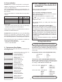
Betriebsanleitung Bandsäge
D
ENG
Operating Instructions for Band Saw
115 168 8051 / 3602 - 1.0 de, en
BAS 500 WNB
D
ENG
Achtung!
Attention!
Lesen Sie diese Anleitung vor der Installation und Inbetriebnahme aufmerksam durch.
Carefully read through these instructions prior to installation and commissioning.
ENG
GENERAL SAFETY INFORMATION
18. ADJUST BLADE TENSION, upper and lower blades
guides, thrust bearings and blade tracking correctly.
19. DOORS AND BLADE GUARD must be in place and
securely fastened when performing saw operations.
20. SECURELY LOCK ALL ADJUSTABLE PARTS so
they can not loosen while sawing. This will prevent
distraction from sawing operations.
21. PLACE THE BLADE GUARD to within 5 mm above
the material to be cut.
22. USE THE PROPER BLADE TYPE AND SIZE for
the material being cut.
23. ALWAYS KEEP HANDS AND FINGERS AWAY
from the saw blade, especially at the end of a cut.
24. DO NOT OVERREACH. Keep proper footing and
balance.
25. HOLD MATERIAL FIRMLY and feed into the blade
at a moderate speed.
26. USE A PUSH STICK OR A PIECE OF SCRAP
WOOD to do the pushing and guiding when sawing
small pieces which require the fingers to be close to
the blade.
27. DO NOT SAW STOCK that does not have a flat
surface unless a suitable support is used.
28. ALWAYS STOP THE MACHINE before removing
scrap pieces from the table.
29. STOP THE MACHINE if the material is to be backed
out of an uncompleted cut.
30. WHEN SAWING CURVES, make relief cuts to allow
for removal of scrap material. This will help to
prevent undue twisting or bending of the saw blade.
The relief cuts are made before starting the curved
cut.
31. NEVER LEAVE A TOOL UNATTENDED. Turn the
power off and do not leave saw until it comes to a
complete stop.
32. DISCONNECT POWER. Turn switch off and
disconnect power whenever the band saw is not in
use.
As with all power tools there is a certain amount of hazard
involved with the operator and his use of the machine.
Using the machine with the respect and caution
demanded as far as safety precautions are concerned
will considerably lessen the possibility of personal injury.
If, however, normal safety precautions are overlooked or
completely ignored, personal injury to the operator can
develop.
1.
2.
3.
4.
5.
6.
7.
8.
9.
10.
11.
12.
13.
14.
15.
16.
17.
FOR YOUR OWN SAFETY READ AND UNDERSTAND THIS INSTRUCTION MANUAL BEFORE
OPERATING THE SAW; Learn the saw's application
and limitations as well as the specific hazards peculiar
to it.
WEAR PROPER APPAREL. Do not wear loose
clothing, gloves, neckties, rings, bracelets or other
jewellery which may get caught in moving parts of
the saw.
WEAR PROTECTIVE HAIR COVERING to contain
long hair.
WEAR SAFETY SHOES with non-slip soles.
WEAR SAFETY GLASSES. Everyday glasses have
only impact resistant lenses. They are no safety
glasses.
WEAR FACE MASK OR DUST MASK if operation
is dusty.
BE ALERT and think clearly. Never operate power
tools when tired, intoxicated or when taking
medications that cause drowsiness.
KEEP WORK AREA CLEAN. Cluttered work areas
and work benches invite accidents.
DO NOT USE POWER TOOLS IN DANGEROUS
ENVIRONMENTS. Do not use power tools in damp
or wet locations. Do not expose power tools to rain.
THE WORK AREA SHOULD BE PROPERLY
LIGHTED.
A PROPER ELECTRICAL OUTLET SHOULD BE
AVAILABLE for the machine. The plug should be
plugged directly into a properly grounded outlet.
EXTENSION CORDS MUST HAVE AN EARTH
LEAD and all three leads must be of the correct
cross section/gauge.
Keep visitors at a safe distance from the work area.
KEEP CHILDREN OUT OF THE WORKPLACE.
Make workshop childproof. Use padlocks, master
switches and remove starter keys to prevent any
unintentional use of power tools.
PERMANENTLY MOUNT YOUR BAND SAW before
performing cutting operations.
KEEP GUARDS IN PLACE and in working order.
MAKE ALL ADJUSTMENTS AND SET-UPS, such
as tilting the table or adjusting the blade guards and
blades guides, WITH THE POWER OFF.
Disclaimer
The information contained in this manual is intended to
make the owner/operator of this band saw familiar with
its set-up and the setting of cutting speeds, fences and
guards.
This is not a maintenance manual for servicing and
repair nor does it teach the operator how to become an
expert woodworker.
7
function which results from improper use or unauthorized
modification from standard specifications, faulty
maintenance, damage or improper repair by anyone
other than qualified persons approved by Elektra Beckum
or its representatives.
Elektra Beckum reserves the right to change
specifications and design without prior notice and
without incurring obligation of any kind.
Equipment referred to as available or optional may
be at extra cost.
Contents
1
2
3
4
5
6
7
8
9
10
11
12
General
Specifications
Machine Installation
Blade Speed Selection
Band Saw Setup
Safety Rules
Additional Information
Connection to Power Mains
Optional Accessories
Dust Collection
Replacement Saw Blades
U.K. Supplement to Operating Instructions
Wiring Instructions
1
General
3
The BAS 500 band saw is used for cutting wood, woodlike materials or plastic across the grain or longitudinally.
Make sure that you always use a band saw suitable for
the material to be cut.
In individual cases the machine can also be used to cut
other materials. Written permission from the company
Elektra Beckum AG (see the section below on product
liability/warranty for the address) is required in such
cases.
Only use the band saw in dry surroundings. Round
materials may only be cut using a suitable supporting
device.
2
Machine Installation
To facilitate better handling and prevent damage to
projecting parts during transport, this machine is shipped
partly disassembled. After unpacking the saw table, rip
fence and crank handle have to be installed before the
saw can be operated.
Remove wrapping and check for any visible damage
which may have occurred during transport. If damage is
detected notify your dealer immediately.
● Remove rip fence carrier extrusion (201) from saw
table (200).
● Place table onto the upper table trunnion (85).
● Bolt to table trunnion with washers Ø 8.4 (108), spring
washers Ø 8.4 (111) and hex. screws M 8 (114).
● Attach rip fence carrier extrusion (201) to the table
with 4 screws (91).
● Press table insert (79) into the saw table. Use table
insert with wide slot (24) only for bevel cuts.
● Insert bolt guide (90) with carriage bolt M 8x50 (101)
into the rip fence carrier extrusion's T-slot.
● Place rip fence carrier (88) onto carriage bolt (101)
and secure with washer Ø 8.4 (108) and wing nut M
8 (135).
● Attach rip fence extrusion (87) to rip fence carrier with
2 each carriage bolts M 6x40 (102), washers Ø 6.4
and knurled nuts M 6 (99).
● Bolt the crank handle (70) to handwheel (20) with cap
screw M 5x55 (105) and a hex. flat nut M 6 (115).
Counter screw with the hexagon nut so it will not
loosen.
After assembly the table needs to be aligned to have the
blade running through the centre of the table insert's slot.
Specifications
Height x Width x Depth:
2020 x 830 x 770 mm
Weight:
approx. 159 kg
Table height from floor:
945 mm
Throat capacity:
440 mm
Max. height of cut:
300 mm
Saw blade
length/width:
3380/6-25 mm
Saw table:
535 x 720 mm
tilts from 90° through 45°
Blade speeds: 50 Hz
68-176-375-967 m/min
Motor:
1.1 kW/1.5 hp 230 V / 50 / Hz 1-phase
Noise information according to DIN 45635:
idling
under load
Sound power level:
85 dB(A)
90 dB(A)
Workplace related noise
emission value:
75 dB(A)
82 dB(A)
Table side alignment:
● Loosen the mounting screws of the lower table trunnion
(84).
● Move table trunnion to left or right, as required.
● Tighten mounting screws, making sure the table stays
in the set position.
User Responsibility
This machine will perform in conformity with the
description contained in the instructions provided. This
machine must be checked periodically. Defective
equipment (including power cables) should not be used.
Parts that are broken, missing, plainly worn, distorted or
contaminated, should be replaced immediately. Should
such repair or replacement become necessary, it is
recommended that such repairs are carried out by
qualified persons approved by Elektra Beckum or its
representatives.
This machine or any of its parts should not be altered or
changed from standard specifications. The user of this
machine shall have the sole responsibility for any mal-
Setting table square to the blade:
● For bevel cuts the table tilts from 90° steplessly
through 45°. Loosen the wing nut (135) on the table
trunnion (84) to adjust the table position.
● Underneath the table a stop is installed, which rests on
the saw housing when the table is in the 90° position.
8
● Adjust the hex. head screw of the stop to set the table
exactly square with the blade.
● After the stop is adjusted, stick the rip fence scale (89)
to the rip fence carrier (201).
5
Band Saw Setup
Blade Speed Change
To change the cutting speed, the V-belts must be changed
on the pulleys as shown in the table inside the lower
wheel housing door.
For an easy belt change a quick-action tensioning device
is provided, actuated by the handwheel (20) at the lower
right hand side of the wheel housing.
Saw Blade Changing/Setting
This band saw is supplied with a general purpose
woodcutting blade (stock-no. 090 902 9171), installed
and set.
To change the blade start with removing the rip fence
carrier (201). Then slacken the blade tension by turning
the handwheel (16) on top of the machine housing
counter-clockwise, open both doors and swing the blade
guard out of the way. Remove blade from machine.
Install new blade and tension lightly. Turn upper band
saw wheels by hand to check tracking. The blade must
run in the centre of the wheels or else it may jump off. If
necessary, adjust tilt of upper band saw wheel with
starknob setting screw (28) at the rear of the upper wheel
housing.
If a blade of different width is installed, the guide bearing
of the upper blade guide and the pilot pins of the lower
blade guide must be adjusted so that the teeth are just
running clear of the pilot pins/guide bearings.
For a firm stand and vertical stability the saw must be
bolted to the floor.
430
370
300
30
13
30
Blade Guiding
The blade guides of this band saw model BAS 500
provide for an exact guiding and lateral support of the
saw blade. When using narrow blades a firm guiding by
the upper blade guard is especially important. Ensure
the guide bearings (21) and the thrust bearing (76) are
set closely (to within 0.5 mm) against the blade.
The lower blade guide supports the back of the blade
with a small thrust bearing. Loosen the knurled thumb
screw (78) to adjust the thrust bearing position. Tighten
the thumb screw again. Thus the blade guide keeps the
blade from waving.
533
593
601
Drilling pattern for anchor bolts.
For this purpose four 1/2" holes are provided in the
machine's base. Locations as per drilling pattern shown
above.
4
For wide band saw blades (from 13 mm/1/2 in.) the guide
bearings should not be used as, due to increased friction,
considerable heat is generated which may damage the
bearings. Retract guide bearings fully to clear the blade.
A wide blade is also thicker and strong enough to keep
it from waving.
Blade Speed Selection
This band saw can be set to four different cutting speeds
for best possible cutting results in different materials.
The cutting speed most suitable for the material to be cut
should be determined by making trial cuts in scrap
material.
Cutting Height Setting
The upper blade guide should always be
set as close as possible against the
workpiece. To adjust, loosen the ratchet
lever and set the height with the handwheel
(27). Tighten ratchet lever after setting.
Depending on the type of blade used and material to be
cut, the following recommendations are given:
a) 68 m/min
- certain low-carbon steel, gas
aerated concrete blocks
b) 175 m/min
- NF-metals and most plastics
c) 375 m/min
- hardwood, certain plastics
and NF-metals
d) 967 m/min
- all species of wood
Ratchet lever operation:
To unlock the catch pull lever, it then can swivel freely.
To adjust bolt, release lever to engage catch and loosen/
tighten bolt as required.
9
Saw Table Tilt
- For bevel cuts the table can be tilted up to 45°. Loosen
the wing nut (135) of the table trunnion assembly, tilt
the table to the required position and retighten the wing
nut. Make trial cut in a piece of scrap wood to verify
setting to desired angle.
- Hand guards:
Prior to tilting the two hand guards on the underside of
the table must be moved towards the fence guide
extrusion to clear the blade when the table is tilted.
7
6
8
Additional Information
For this band saw a range of optional accessories is
available. Both the band saw and the accessories are
only to be used for operations as described in this
manual or in the instructions supplied with the
accessories. Please contact your supplier or local agent
if you require additional technical information.
Safety Rules
1. Always disconnect from power when changing blades
or servicing the machine.
2. Before switching machine on be sure that all guards
are in place and securely locked.
3. Do not use cracked or bent saw blades.
4. Replace table inserts (24/79) if slot has enlarged.
5. For cutting operations with tilted table the rip fence
must be placed to the right of the blade.
6. When cutting round stock use a suitable jig to prevent
the work from turning.
7. When cutting boards in an upright position use a
suitable push block to prevent kickback.
8. Before tilting the table for bevel cuts replace the table
insert (79) with the wide slot table insert (24).
9. For safe operation and to keep dust emission within
the legal limits a dust collector with a minimum air flow
rate of 20 m/s must be connected to this band saw.
Connection to Power Mains
Damaged power cables must be replaced immediately
by a qualified electrician. Risk of electric shock if
operated with a damaged power cable.
Children and juveniles should not to operate this machine.
This band saw is equipped with a 1.1 kW 230 V singlephase motor. For connection to power mains the power
cable is fitted with an earthed plug.
All models are equipped with an electronic brake. A light
humming sound emitted from the switch for a short
period after connection to power is normal and does not
indicate a fault. If the brake fails have the fine-wire fuse
inside the switch checked. The max. permissible number
of 20 switching actuations per hour should not be
exceeded.
The electrical installation must ensure that a dust collector
starts up when this band saw is switched on (e.g. with an
induction coil in the supply lines).
9
Optional Accessories
Circular Cutting Attachment
Stock-no. 090 903 1249
For cutting radii from 30 to 260 mm.
Belt Sanding Attachment
Stock-no. 090 903 1087
Quick and simple adaption of the belt sanding attachment
to the saw. For finishing the cut edge or deburring.
Because of the many different plastics available the
proper sanding belt speed must be found by testing.
Wheel Set
Stock-no. 090 900 0505
Fitting the wheel set to the machine makes the saw
mobile.
Precision Blade Guide
Stock-no. 090 901 0896
- Higher precision and better performance of the saw.
- TCT guide bearing for longer service life.
- Requires no tools for setting and replacing the guide
and thrust bearings.
10
10 Dust collection
12 U.K. Supplement to Operating
Instructions for Elektra Beckum Band
Saw BAS 500
Caution! Dust of certain wood spezies is carcinogenic.
➜ When operating your woodworking machine indoors
connect to a dust collector.
➜ If a woodworking machine is operated indoors for
more than 30 minutes, it is mandatory to connect it to a
dust collector.
Please note the following supplementary information
associated with this machine:
U.K. Legislation and Codes of Practice
When used industrially within the U.K. this machine
falls under the scope of
● Woodworking Machines Regulations 1974
and
● Use and Provisions of Work Equipment
Regulations 1992
Important information to consider when choosing a dust
collector:
Port diameter
Mean air speed
Vacuum
Volume flow rate
Unit
mm
m/s
Pa
m3/h
Min. value
100
20
1640
565
We strongly advise you study and follow these
regulations.
Please note:
- The airflow at the suction port (of the woodworking
machine) should not be less than 20 m/s.
Section 5.0 - Connection to Power Mains
230 V motor. Although the motors supplied with this
machine will run safely on a 13 A domestic ring main,
on starting the machine a high current of very short
duration is drawn, which could cause your 13 A fuse
to blow. If this persists we recommend to have the
machine connected to a 16 A separate radial circuit
using BS 4343 (CEE 17) plug and socket. Ensure the
installation is protected by a suitable fuse or miniature
circuit breaker.
This work should be undertaken only by a qualified
electrician!
Check with your dealer on the different dust collectors
available from Elektra Beckum.
Caution! With extented daily use of your woodworking
machine an automatic start/stop device, which
automatically switches the dust collector on and off when
the woodworking machine is started/stopped, is required.
This automatic power relay is available in two different
versions from Elektra Beckum:
- Automatic Power Relay ALV 1
1~230 V
stock-no. 091 301 4626
Wiring Instructions
Warning: This appliance must be earthed!
If the plug, fitted to the power cable supplied with the
machine, has to be changed or replaced, connect the
mains lead conductors in accordance with the following
colour code.
11 Replacement Saw Blades
Standard delivery: blade with induction-hardened teeth
for a longer tool life.
Single-phase motors (110/115/220/230/240 volts):
General purpose blade for straight and
contour cuts, 3380x15x0.5 mm
tooth spacing A 6 mm
Stock-no. 090 902 9171
Yellow/green
Blue
Brown
Blade for wood contour cuts
3380x6x0.5 mm
tooth spacing A 4 mm
Stock-no. 090 902 9180
Earth
Neutral
Live
Three-phase motors (220/380/400/415/440 volts):
Machines with a 3-phase motor are connected to power
mains using a 5-pin industrial appliance-inlet/connector
according to VDE 0623/BS 4343/IEC 309.
Blade for straight cuts
3380x25x0.6 mm
tooth spacing A 4 mm
Stock-no. 090 900 0416
Blade for cutting fire wood
3380x25x0.6 mm
tooth spacing A 8 mm
Stock-no. 090 900 0424
Blade for NF-metals
3380x15x0.5 mm
tooth spacing A 2 mm
Stock-no. 090 902 9210
Blade for carbon steel
3380x13x0.65 mm
tooth spacing 14 teeth/inch
Stock-no. 090 902 9229
-
4-wire mains lead Yellow/green
Brown
Black
Blue
-
Earth
Phase (L1)
Phase (L2)
Phase (L3)
5-wire mains lead Yellow/green
Brown
Black
Black
Blue
-
Earth
Phase (L1)
Phase (L2)
Phase (L3)
Neutral
IF IN DOUBT - CONSULT A QUALIFIED ELECTRICIAN!
11