1
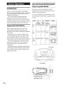
VISUAL PARKING ASSIST SENSOR
SYSTEM (VPASS)
VPX-B104R
• OWNER'S MANUAL
Please read before using this equipment.
• MODE D'EMPLOI
Veuillez lire avant d,utiliser cet appareil.
• MANUAL DE OPERACION
Lealo antes de utilizar este equipo.
ALPINE ELECTRONICS MARKETING, INC.
ALPINE ELECTRONICS OF AUSTRALIA PTY. LTD.
ALPINE ITALIA S.p.A.
1-1-8 Nishi Gotanda,
Shinagawa-ku,
Tokyo 141-0031, Japan
Phone 03-5496-8231
161-165 Princes Highway, Hallam
Victoria 3803, Australia
Phone 03-8787-1200
Vi ale C. Colombo 8, 20090 Trezza no
Sui Naviglio (MI), Italy
Phone 02-484781
ALPINE ELECTRONICS GmbH
ALPINE ELECTRONICS DE ESPAAA, S.A.
Wilhelm-Wagenfeld-Str. 1-3,
80807 Munchen, Germany
Phone 089-32 42 640
Portal de Gamarra 36, Pabell6n, 32
01013 Vitoria (Aiava)-APDO 133, Spain
Phone 945-283588
ALPINE ELECTRONICS OF U.K. LTD.
ALPINE ELECTRONICS (BENELUX) GmbH
Alpine House
Fletchamstead Highway,
Coventry CV4 9TW, U.K.
Phone 0870-33 33 763
Leuvensesteenweg 51 0-86,
1930 Zaventem, Belgium
Phone 02-725-13 15
ALPINE ELECTRONICS OF AMERICA, INC.
19145 Gramercy Place, Torrance,
California 90501, U.S.A.
Phone 1-800-ALPINE-1 (1-800-257-4631)
ALPINE ELECTRONICS OF CANADA, INC.
777 Supertest Road, Toronto,
Ontario M3J 2M9, Canada
Phone 1-800-ALPINE-1 (1-800-257-4631)
ALPINE ELECTRONICS FRANCE S.A.R.L.
(RCS PONTOISE B 338101 280)
98, Rue de Ia Belle Etoile, Z.l. Paris Nord II,
B.P. 50016,95945 Roissy Charles de Gaulle
Cedex, France
Phone 01-48638989
a
ENGLISH
Contents
Operating Instructions
WARNING
DANGER ........................................... 2
WARNING ........................................ 2
CAUTION ......................................... 3
NOTICE ............................................. 5
Sensor Operation
Introduction ....................................... 6
Important Information ..................... 6
How the Visual Parking Assist
Sensor System Works .................... 6
Installation and Connections
Installation Diagram ......................... 7
1. Sedan ...................................................... 7
2. Pickup Truck ......................................... 7
Accessory Parts .................................. 8
Component ................................................ 8
Installation Tool ........................................ 8
Wire Connection ............................... 9
Painting Sensor Cover and
Sensor Unit ................................... 10
Sensor Assembly Painting Method ....... 10
Sensor Assembly.............................. 11
Installation of Sensor ...................... 13
Installation of ECU ......................... 15
On-Screen Display Set Up ............. 15
Fish-eye Correction Menu ..................... 16
Parking Guide Line Adjustment ........... 16
Diagnostic ................................................ 17
Setup Mode Structure Tree ............ 18
Function Test after Installation ..... 19
In Case of Difficulty ........................ 19
l-EN
Operating Instructions
WARNING
it DANGER
This symbol means important instructions.
What to do in the case of an extremely critical
situation wherein someone may suffer grave
or mortal injury.
DO NOT PROCEED TO BACK UP YOUR VEHICLE WHILE
PEOPLE ARE IN YOUR VIEW OR THE CAMERA'S VIEW.
SERIOUS INJURY OR DEATH CAN RESULT.
it WARNING
This symbol means important instructions.
Failure to heed them can result in serious
injury or death.
WHEN USING SYSTEM, THE DRIVER MUST VISUALLY
CHECK ACTUAL CONDITIONS AROUND THE VEHICLE.
MAKE SURE THERE ARE NO PERSONS OR ANIMALS
IN THE AREA IN WHICH YOU ARE MANEUVERING
OTHERWISE YOU COULD INJURE THEM.
A camera assists the driver by sending images to the screen
showing conditions in view of the camera. The camera uses
a wide-angle lens, therefore, there is a difference in distance
perspective between what is normally seen and what appears
on the screen. Also, the images shown by the rearview camera
are reversed, so as to appear the same as what is seen through
the rearview mirror.
The system may not perform to full capability due to
variables such as:
• weather conditions such as hard rain, snow, fog or mud
• extremely high or low temperatures near camera and/
or sensor
• slope of vehicle and/ or roadway
• direct exposure to very bright light such as headlamp or
bright sunlight
• moving from very dark to very bright light and vice versa
such as in parking garages or tunnels
• .extremely low light areas
• walls or objects that are located diagonally in relation to
the camera
• retracted mirrors that change camera viewing angle
• open doors or trunks
• changes to height of vehicle due to loading capacity or
hydraulic suspensions
• objects located at the corner of the vehicle
CHECK THAT THE CAMERA AND/OR SENSOR MOUNTING
IS ATTACHED SECURELY, ANDTHATTHE SCREWS ARE
TIGHT BEFORE DRIVING.
Failure to do so may result in an accident.
WHEN INSTALLING OR CHECKING A CAMERA AND/OR
SENSOR, DO SO AFTER PARKING THE CAR IN A LEVEL,
SAFE PLACE, TURNING OFF THE ENGINE, AND APPLYING
THE HAND BRAKE.
Failure to do so may result in an accident.
2-EN
WHEN INSTALLING CAMERA AND/OR SENSOR, BE
SURE TO USE SPECIFIC VEHICLE CALIBRATION KIT
OTHERWISE IT WILL NOT ACCURATELY DISPLAY
IMAGES.
Failure to do so may result in an accident.
MINIMIZE DISPLAY VIEWING WHILE DRIVING.
Viewing the display may distract the driver from looking
ahead of the vehicle and cause an accident.
DO NOT DISASSEMBLE OR ALTER.
Doing so may result in an accident, fire or electric shock.
KEEP SMALL OBJECTS SUCH AS BOLTS OR SCREWS OUT
OF THE REACH OF CHILDREN.
Swallowing them may result in serious injury. If swallowed,
consult a physician immediately.
USE THE CORRECT AMPERE RATING WHEN REPLACING
FUSES.
Failure to do so may result in fire or electric shock.
MAKE THE CORRECT CONNECTIONS.
When making connections to the vehicle's electrical system,
be aware of the factory installed components (e.g. on-board
computer). Do not tap into these leads to provide power
for this unit. When connecting the device to the fuse box,
make sure the fuse for the intended circuit of the device has
the appropriate amperage. Failure to do so may result in fire
or damage to the unit and/ or the vehicle. When in doubt,
consult your Alpine dealer.
BEFORE WIRING, DISCONNECT THE CABLE FROM THE
NEGATIVE BATTERY TERMINAL.
Failure to do so may result in electric shock or injury due to
electrical shorts.
DO NOT ROUTE ELECTRICAL CABLES NEAR HOT OR
MOVING PARTS.
Route the cables and wiring away from hot or moving parts,
and fix them securely to avoid heat/mechanical damage to
the cable insulation, which may result in a short circuit, fire
or electric shock.
DO NOT SPLICE INTO ELECTRICAL CABLES.
Never cut away cable insulation to supply power to other
equipment. Doing so will exceed the current carrying
capacity of the wire and result in fire or electric shock.
DO NOT INSTALL IN LOCATIONS WHICH MIGHT HINDER
VEHICLE OPERATION, SUCH AS THE STEERING WHEEL
OR SHIFT LEVER.
Doing so may obstruct forward vision or hamper movement
etc. and results in serious accident.
DO NOT DAMAGE PIPE OR WIRING WHEN DRILLING
HOLES.
When drilling holes in the chassis for installation, take
precautions so as not to contact, damage or obstruct pipes,
fuel lines, tanks or electrical wiring. Failure to take such
precautions may result in fire.
DO NOT USE BOLTS OR NUTS IN THE BRAKE OR
STEERING SYSTEMS TO MAKE GROUND CONNECTIONS.
Bolts or nuts used for the brake or steering systems (or any
other safety-related system), or tanks should NEVER be used
for installations or ground connections. Using such parts
could disable control of the vehicle and cause fire etc.
DO NOT ALLOW CABLES TO BECOME ENTANGLED IN
SURROUNDING OBJECTS.
Arrange wiring and cables in compliance with the manual
to prevent obstructions when driving. Cables or wiring that
obstruct or hang up on places such as the steering wheel, shift
lever, brake pedals, etc. can be extremely hazardous.
USE THIS PRODUCT FOR MOBILE 12V APPLICATIONS.
Use for other than its designed application may result in fire,
electric shock or other injury.
USE ONLY IN CARS WITH A 12 VOLT NEGATIVE GROUND.
(Check with your dealer if you are not sure.) Failure to do so
may result in fire, etc.
WHEN USING A DRILL TO MAKE A HOLE, TAKE
PRECAUTIONS SUCH AS WEARING GOGGLES SO
FRAGMENTS DO NOT GET INTO THE EYES.
Failure to do so may result in injury.
CALIBRATION REQUIRED.
Calibration may be required for adjusting parking guideline.
BE CAREFUL WHEN SETTING THE ALARM VOLUME.
Set the alarm volume to an audible level. If the alarm cannot
be heard due to the volume of the car radio, etc., it might
result in an accident.
6CAUTION
ARRANGE THE WIRING SO IT IS NOT CRIMPED.OR
PINCHED BY A SHARP METAL EDGE.
Route the cables and wiring away from moving parts (like
the seat rails) or sharp or pointed edges. This will prevent
crimping and damage to the wiring.
HALT USE IMMEDIATELY IF A PROBLEM APPEARS.
Failure to do so may cause personal injury or damage to the
product. Return it to your authorized Alpine dealer or the
nearest Alpine Service Center for repairing.
CHECK WIRING WHEN ATTACHING.
Double-check your wiring to ensure all connections are
correct and secure. Also, do not apply unnecessary force to
the harness. This can result in battery failure, performance
failure, connector damage, or wire breakage.
This system uses ultrasonic sensors to help sharpen the
driver's detection of obstacles. It is used when parking in a
garage or a narrow passage. As such, this system does not
relieve the driver of the obligation to pay attention to his/
her driving, and the driver should exercis~ safe driving habits
without relying heavily on this system. The detection range
of the Visual Parking Assist Sensor System (VPASS system) is
restricted to the area around the bumper. When moving the
car either forward or backward, drive slowly and keep a safe
distance around the vehicle. To ensure the sensors function
accurately, never install accessories in close proximity to the
sensors.
This symbol means important instructions.
Failure to heed them can result in injury or
material property damage.
DO NOT ATTACH THE CAMERA AND/OR SENSOR
MOUNTING TO FLUOROCARBON RESIN FINISHED CAR
BODIES OR GLASS.
Doing so could cause the strength of the mounting to
weaken, which could cause it to fall of and cause accidents,
injury, or damage to the car body.
DO NOT ATTACH THE CAMERA AND/OR SENSOR
MOUNTING TO ANY SURFACE WHERE THE ENTIRE
ADHESIVE SURFACE CANNOT BE APPLIED.
Doing so could cause the strength of the mounting to
weaken, which could cause it to fall of and cause accidents,
injury, or damage to the car body.
EXCEPT FOR THE CAMERA AND/OR SENSOR, DO NOT
ATTACH ANY PARTS TO AREAS WHICH WILL GET WET,
OR WHERE THERE IS A LOT OF HUMIDITY OR DUST.
Failure to do so may result in fire or damage.
1
The detecting function might not
operate properly under the following
conditions:
• When the detection sensors become frozen. (Normal
function resumes after defrosting.)
USE SPECIFIED ACCESSORY PARTS AND INSTALL THEM
SECURELY.
Be sure to use only the specified accessory parts. Use of other
than designated parts may damage this unit internally or may
not securely install the unit in place. This rna y cause parts to
become loose resulting in hazards or product failure.
HAVE THE WIRING AND INSTALLATION DONE BY
EXPERTS.
The wiring and installation of this unit requires special
technical skill and experience. To ensure safety, always
contact the dealer where you purchased this product to
have the work done.
3-EN
• When the detection sensors are clogged with foreign matter
such as show, mud or icicles. (Normal function resumes
after removal.)
3
The Parking Corner Sensor might
not be able to detect the following
objects:
• Rope, wire, small-diameter pipes or objects made of these
materials, such as wire fences.
• When a detection sensor is subject to a strong impact.
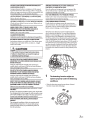
~.· · ~~
._· -.-~··.\·····i
. ·. ~· · · · ·. ·
. -
2
·-».
~
~-----~
·-.....
·--
.. D ...
-:·»······,·············
• Objects that absorb sound waves easily, such as fabrics or
other soft, absorbent materials.
•
•
The detecting range could decrease
under the following conditions:
•
• When the vehicle is parked for a long period of time in the
sunlight or in cold weather.
•
•
•
• • • • • •
• •
• •
•
•
•
•
• When a sensor is covered by something. (The function
resumes after removal.)
• When the detection sensors are clogged with mud, snow
or icicles.
• When the vehicle is parked at extreme angles in relation to
surrounding objects.
4:.EN
• When getting too close to an obstacle (< 0. 7ft) as the
sensors might have a false detection; for example: no beep,
slow beep, fast beep or three fast beeps.
• Non-reflecting objects that project at sharp or acute angles
in relation to the sensors.
-~---
Slant
---·~-
• Objects around the lower part of the bumper. Even if the
sensors detect a low object initially, when the vehicle is
driven closer to the object, the buzzer might suddenly stop
beeping.
• Heavy rain or a large amount of water (or splash) on the
sensors.
Caring for the Backup Sensors
Obstacles being lowered from above, such as a garage door.
1. Wipe the sensors clean with a clean cloth. Flush with low-
pressure water if the sensors are clogged with mud or dirt.
2. Do not spray the sensors with high-pressure water, as
provided at a self-serve car wash.
NOTICE
Obstacles that project out high above the floor.
• When washing the vehicle, do not use an automatic car
washer, or high-pressure washer. Doing so could cause the
camera and/or object sensor to come off, damage to the
device cords, or may allow water to enter the camera and/
or object sensor.
• In some cases, to attach the device, a hole must be drilled
in the car body, requiring use of touch-up paint (retail
product) for rust-prevention, and should be prepared
beforehand.
• Route the cables and wiring away from hot or moving
parts, and fix them securely to avoid heat/mechanical
damage to the cable insulation, which may result in shortcircuit, fire or electric shock.
5-EN
Sensor 0 eration
Introduction
Thank you for purchasing this Visual Parking
Assist Sensor System (VPASS system). Please read
this User's Information Manual carefully before
using the VPASS system.
This Owners Manual contains important
information about the safe operation of the
VPASS system. We urge you to read this manual
carefully, and follow its recommendations to help
make your driving trouble-free and enjoyable.
Important Information
Before using the backup sensors, make sure
you read and understand the operation and
limitations of the system as discussed throughout
this manual.
The backup sensors make an audible sound
when they detect large stationary objects while
maneuvering the vehicle in reverse gear at low
speed. However, not all obstacles may be detected.
Even with backup sensors, the driver should
always look for obstacles near the vehicle and
make sure the path is clear when driving in
reverse gear.
Never rely solely on the backup sensors; always
look behind you before backing up. The sensors
may not always detect people or animals in the
path of your vehicle.
How the Visual Parking Assist
Sensor System Works
The system is ready for operation when the
ignition switch is turned ON and the shift lever is
moved to the reverse position.
The visual parking assist sensor system alerts
you with an audible signal and visual alert when
the rear bumper of your vehicle is approaching an
obstacle.
Sound
On-
On-
screen
screen
to
Message
Color
obstacle
Distance
Within
3-6ft
Slow
beep
No message GREEN
Fast
beep
CAUTION YELLOW Within
3-l.Sft
WARNING RED
Continuous
beep
Display
Within
0.7-1.5 ft
Back Sensor
Corner Sensor
Cil:l
Continuous beep (0.7 to 1.5 ft.)
Fast beep (3 to 1.5 ft.)
Slow beep (3 to 6 ft.)
6-EN
n
Dl
c
,..
cr:::J
Installation and
Connections
For your protection, please pay extra attention to
the following symbols.
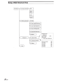
Installation Diagram
1.Sedan
Sensor
~CAUTION
This symbol is intended to alert the user that
an accident, injury or vehicle damage may
occur if the instruction is not observed.
Monitor
SUGGESTION
This symbol is intended to give the user a
better understanding for safer or easier use
of the system.
Buzzer
ECU
• Buzzer can be installed anywhere within
10ft. (3m).
• ECU MUST be installed inside vehicle.
• Sensor cable must be installed from left to right.
2. Pickup Truck
• Buzzer can be installed anywhere within
10ft. (3m).
• ECU MUST be installed inside vehicle.
• Sensor cable must be installed from left to right.
• Optional extension cable (KWE-104PS) may be
required.
7-EN
Component
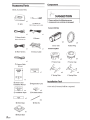
Accessory Parts
Check Accessory Parts.
~
CD
SUGGESTION
Please confirm the following sensor
components are not dirty or damaged.
x1
(2) Sensor *4
ECU
Refer to Component section for detail.
Sensor Unit Box
x1
x1
@ Setup Switch
@Buzzer
Without "Grommet" Part
x1
@Main Harness
x4
-
Sensor Unit
x1
@Sensor Cable
x1
Rubber Ring
Sensor Cap Box
~x4
oo Sensor Cap
~
~x4
6° Sensor Cap
(/) Camera Cable
(3.5 m)
VISO.t.li'MUIG.U.T..,_.
x1
VPX-B104R
x4
x4
0° Spring Plate
6° Spring Plate
x1
Installation Tool
® Owner's and
Installation Manual
x2
® Installation Paper
.____1_a_pe_ ____.l
~x4
8-EN
<®>
15/16 inch (0 24 mm) drill bit is required.
x4
@ PS Guide Sticker
x2
@Velcro Tape
GID Mount Base
®Registration Card
@Wire Tie
Wire Connection
Video in for HCE-C104 or other RCA video connection
f- Oth;r C~m;r;-(RCA)------------ i
I
I
•i
!I cdl
I
------'
~--------------------------;
r-Hce-e1o4---------
••-•i
I
,...**'./
I
~-
~------------------------J
-
I
To Alpine Camera
To Other Video Monitor
-
(Red)
(Orange/White) I Reverse
I
To Alpine Video Monitor
ACC
-----o
-----o
Reverse
(Black)
Buzzer
Buzzer
6...
I SetupSWI
Parking Sensors
Sensor Cable
For Pickup Truck
For Sedan
HCE-C117D
M5
Setup Switch
Alpine Monitor
M6 System
F5
- ---·-·-·--·-·-·-·---'~-:--.M-:____5
~:;_:_~-----i r·---Fs______
·------'-----------------M6-~6~
-----·
·- ·,·--·-·-
55
1 -·~-·
-·-·-·:,~--~--~· - · - · -·-· ~-~-~· - · - · - · ~
-_-_-_-_-_-_-_-_-_-_-_j :
-~
HCE-C117D
M5
·-
M6
F5
3.5m
(Q}--1--, ~-·1
Alpine Monitor
System
.
.- ,~~~~~~-~--~; - ·c~~~~--~:~~~~~:~--~~~~~~~:~.-~:ij~j~-~-~~~--~ :~~~~~~~-~-~~~~~1· -· - ~
li ::.....
10m
~----------j '
I -~-
~ -- - - ------ - ------- - -- - - - -------- - ------- ~
Note:
* Connect only one camera to the system using the Alpine Camera connector or RCA video in.
* Connect only one monitor to the system using the Alpine Video cable or RCA video out.
*Use the Alpine video cable (provided with system) to connect between the VPASS system and video monitor or between VPASS and Alpine camera
9-EN
Painting Sensor Cover and
Sensor Unit
Please follow the instructions in this manual for
painting and assembling, in order to get the best
performance.
~CAUTION
• Use only the painting and assembling
methods detailed in this manual.
• Damages resulting from the failure to use the
methods detailed in this manual are not our
responsibility.
• Install sensors on the vehicle bumper after
painting and assembling.
• Please refer to the Installation Manual for
installing sensors on the vehicle bumper.
• Immediately clean the surface of the sensors
with a soft cloth if they contact any fuel, oil,
coolant, battery acid, sealants, adhesives, car
care products, or any other substance that
could cause damage.
3
4
5
Remove the sensor box cap.
Remove the rubber ring from the
sensor unit box to avoid painting.
Evenly apply 2 or 3 base coats,allow
each coat to dry before recoating.
Note: Avoid painting the rubber ring around
the sensor.
i,~
.i(
i/"'../
I
.....!!!l!!"""-"!1!!~-.:!!!!!!!!-~..
6
Sensor Assembly Painting Method
1
Remove the spring plate from the
sensor cap box to avoid painting.
7
--
'
.
0 .~-(i,UtTilt 015 *&tt.e
I
Evenly apply 2 or 3 clear coats. For
temperatures under 60° F, allow each
coat to dry for 30 minutes before
recoating.
When completely dried and hardened,
proceed to the sensor installation
instructions.
CoatingThickness Suggestion:
Base coat: (15 ,.... 30 IJm);
Clear coat: (25 ,.... 30 IJm)
2
10-EN
Check if any accessories are missing
and all accessories are aligning/
assembling properly.
~CAUTION
• Limit the use of"Spray Paint" to apply the
coatings.
• Depending on the paint manufacturer, the
instructions for painting will vary.
• The sensor unit has been pre-painted with a
base coat, but additional coats are required.
• Before painting, make sure the box is free of
all oil and dust.
• Apply the coats from a distance of 0.5 to 0.8
ft, with a tilt of 45 degrees.
• Do not let the coating adhere to the terminal
and rubber during the time of painting.
• The sensor's performance will be reduced if
the coating's thickness is uneven.
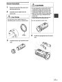
Sensor Assembly
1
2
LtcAUTION
Remove the cap from the sensor unit
after the paint is dry.
Install the sensor rubber into the
sensor unit.
LtcAUTION
The side of the sensor rubber with the 12
noticeable points must face the SENSOR UNIT.
1
Bumps
3
• Do not damage the coating surface when
installing the rubber ring and sensor cap.
• Confirm the installation is not loose when
installing the rubber ring and sensor cap.
• Make sure the rubber ring is not deformed
when the sensor cap is installed into the
sensor unit.
• Use Superglue where the sensor cap and
sensor unit join, to increase security
(Use the superglue for plastic only)
4
Install the spring plate into the sensor
unit.
Install the sensor cap onto the sensor
unit.
11-EN
5
Install the sensor on the vehicle
bumper.
SUGGESTION
Refer to the Installation of Sensor for
installing sensors on the vehicle bumper.
Before installing sensors on the vehicle
bumper, make sure the painting process of
sensors has been finished.
12-EN
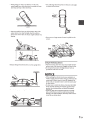
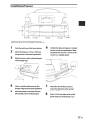
Installation of Sensor
@52
1.6 ft ( in)
1/3 Length
1/3 Length
1/3 Length
Equip the sensor with the oo sensor cap and spring plate for a flat bumper
Equip the sensor with the 6° sensor cap and spring plate for bumper with a slope.
1
2
3
4
5
Park the vehicle on a flat level surface.
6
Mark the bumper at 1.8 to 2.3 ft from
the ground as a horizontal guideline.
Divide the distance between 2 marked
points into three equal lengths. Mark
the points for sensors 52 and 53 so all
sensors are equally spaced.
Mark the center of the vehicle bumper
with masking tape.
Select a smooth surface area on the
bumper along the horizontal guideline.
Mark the bumper 0.4 ft away from the
left and right corners of the bumper.
7
8
Check the size of the hole saw to
match the diameter of the sensors
before drilling any holes.
Drill a 15/16 inch hole at each of the
points that you made in step 1 to 6.
13-EN
9
13
Check behind the bumper to ensure
there is enough depth for sensor
installation.
10
11
12
Install the sensor vertically, with the
"UP" sign facing up.
Install the-sensor-into the hole and
mount firmly in the bumper.
Route the sensor cable.
f~/
~
~~
"'\
rrr;"~~
\ ------------!I
\ \· \ \ I ~::::--~~
----:::;:-----:----=:::::----~~~---
;
I
\\
\
\\ \
~
\. /
/
\(
(.
-
I ----:
-JJJ------~ J
~
-.........
--
_6
14-EN
Insert the plug into the socket.
Installation of ECU
On-Screen Display Set Up
1
Align the calibration paper behind the
car, and up to the rear wheel. Align the
0 ft mark with the rear bumper.
Calibration sheet
Line up bumper with 0 ft
1
2
3
Mount the ECU on a dry, protected
area inside the vehicle. For example,
behind the trunk panels or under the
seats.
Connect the red wire to the ACC (+),
the black wire to ground(-) of vehicle.
Connect reverse signal{+) to the
Calibration sheet
2
3
orange/white wire.
On screen color with distance obstacle:
RED (less than 1.5 ft), YELLOW
(1.5- 3ft), GREEN (3-6ft).
Press the [ENT] and [ +] buttons for
5 seconds continuously to enter the
On-Screen Display set-up mode.
4
Each item in the [Setup mode] can be
selected by pressing the [ + ], [-] and
[ENT] buttons.
Following items can be adjusted in
Setup mode.
1. Fish-eye correction
2. Parking Guide Line
3. Diagnostic
4. Exit
15-EN
Fish-eye Correction Menu
2
To go to Fish-eye correction menu, refer to
step 1 through 4 of On-Screen Display Set-up
section.
1
2
In the fish-eye correction menu, press
the [ENT] button to enter the fish-eye
correction sub-menu.
3
4
Each item in the [fish-eye correction]
can be selected by pressing the [ENT].
Start with OFF, FEC 1 to 7 to avoid
5
screen distortion.
3
After Fish-eye Correction is completed,
returrn to the [Setup Mode] menu by
pressing the [ENT.]
- --
-
6
7
8
- - · ·- -
9
10
1. Fish-eye Correction
11
12
13
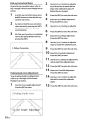
Parking Guide Line Adjustment
To go to Parking Guide Line Adjustment,
refer to step 1 through 4 of On-Screen
Display Set-up section.
1
Select the "Line Length Adjustment'~
Press the [ENT] to enter.
2.Parking Guide Line
ine Length Adjust
16-EN
nt
14
15
Use the [ +1or [-1button to adjust the
top of Green line to match the back
edge of the calibration paper, 6ft
behind the rear bumper.
Press the [ENT] to enter the sub-menu.
Select the "Line Width Adjustment'~
Press the [ENT] to enter.
Use the [ +1or [-1button to adjust the
width to match the calibration paper.
Press the [ENT] to enter the sub-menu.
Select the "Line Slope Adjustment'~
Press the [ENT] to enter.
Use the [ +] or [-] button to adjust the
slope to match the calibration paper.
Press the [ENT] to enter the sub-menu.
Select the "Line Ratio Adjustment'~
Press the [ENT] to enter.
Use the [ +] or [-] button to adjust the line
ratio to match the calibration paper.
Press the [ENT] to enter the sub-menu.
Select the "Line Shift Adjustment'~
Press the [ENT] to enter.
Use the [ +] or [-] button to adjust the
line shift to match the calibration
paper.
Press the [ENT] to enter the sub-menu.
7
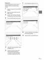
Diagnostic
Press the [ENT] to enter the sub-menu.
To go to Diagnostic menu, refer to step 1
through 4 of On-Screen Display Set-up
section.
1
Select the "Diagnostic'~ Press the [ENTJ
to-enter.
2
Select the "System status'~ Press the
lENT] to enter.
3
Use the[+] or[-] button to review the
"Firmware Version" and "Sensor Status'~
4
Press the [ENT] to enter the sub menu.
Fish-eye Correction
Line Length
Line Shift
Line Slope
Line Ratio
Firmware Version
P1002-08-02
60
05
8
Select the "RETURN'~ Press the [ENT] to
enter the [Setup Mode].
9
Select the "Exit'~ Press the [ENT] to exit.
Sensor
\
J
5
Select the "Function Parameter'~ Press
the [ENT] to enter.
6
Use the[+][-] button to review the
function parameter of Fish-eye
correction, Line Length, Line Width,
Line Shift, Line Slope and Line ratio.
17-EN
Setup -Mode Structure Tree
~etup Mode m
1. Fish-eye correction
mL-O_ff_____.
YReturn
2. Parking Guide Line
2-2 Line Length Adjustment
2-3 Line Slope Adjustment
2-4 Line Shift Adjustment
2-5 Line Ratio Adjustment
1
1
I
3. Diagnostic
3-1 System Status
3-2 Function Parameter
3-3 Return
18-EN
,----------------,
1
Firmware Version
I
P1 002-08-03
:
: Battery Voltage
12.8V
1 Sensor Status
I
S1 :OK 52 :OK 53 :OK 54 :OK
~----------------,
: Fish-eye correction
1 Line Length
: Line Shift
: Line Slpoe
1 Line Ratio
008
005
058
045
045
1
1
Function Test after
Installation
Turn on the vehicle's ignition switch and shift into
reverse. Use a flat board (2 x 2 ft) behind the car
to test the functions as described in the manual.
Refer to- the troubleshooting guide if a problem
arises.
In Case of Difficulty
1. If a problem found with the sensor, the system
will make three short beeps, then silence for
one second. This audio signal occurs five times
and the following message is displayed for 5
seconds.
a) Check the cable connection to the sensor.
b) Check whether the sensor wires are plugged
into the ECU properly.
c) Check the sensor wires for damage.
lCW®)CSJ)~J
NG OK OK OK
?
EASE CHECK SYST'
2. Perform the following checks if the audible
signal does not sound when the vehicle is
approaching an obstacle.
a) Check whether the sensor surface is clean.
b) Check whether the sensor wires are plugged
into the ECU properly.
c) Check the sensor wires for damage.
• Ask an Alpine authorized dealer for advice if the
trouble persists.
3. Take your vehicle to an Alpine authorized
dealer if you encounter either of these problems:
a) The audible signal sounds continuously when
the shift lever is in the reverse position, and
the sensors are not frozen or clogged with
snow or mud.
b) The audible signal does not sound when the
shift lever is moved to the reverse position.
19-EN
5KMG006334XAOOOX
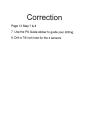
Correction
Page 13 Step 7 & 8
7. Use the PS Guide sticker to guide your drilling.
8. Drill a 7/8 inch hole for the 4 sensors.
Thank you for choosing Alpine for your car audio equipment needs. Our goal is to
produce the best audio/video/navigation products in the world and hope your
expectations are met.
Please take a moment to protect your purchase by registering your product now at
the following address: www.alpine-usa.com/registration. You will be informed of
product and software updates (if applicable), special promotions, and news about
Alpine.
Also, by registering your product, you can enter for a chance to win prizes!
We look forward to continue serving you in the future.
Sincerely,
The Alpine Team
French
Spanish
Nous vous remercions d'avoir porte votre choix sur un
equipement audio automobile Alpine. Notre principal
objectif est de fabriquer les meilleurs produits audio,
video et de navigation au monde afin de repondre aux
exigences de nos clients.
Agradecemos que haya elegido a Alpine como su
proveedor de equipo de audio para su vehfculo.
Nuestro objetivo es fabricar los mejores productos de
audio, video y navegaci6n del mundo y esperamos
poder cumplir con sus expectativas.
Veuillez prendre quelques instants pour securiser
votre achat en enregistrant votre produit a l'adresse
suivante: www.alpine-usa.com/registration. Vous
serez informe( e) des nouveaux produits, mises a jour
logicielles (le cas echeant), promotions speciales et
informations concernant Alpine.
Para proteger su compra le pedimos que se tome
unos momentos para registrar su producto en Ia
siguiente direcci6n: www.alpine-usa.com/registration.
Recibira informacion sobre novedades del producto,
actualizaciones de software (si su producto lo
requiere ), promociones especiales y noticias sobre
Alpine.
Lors de !'enregistrement de votre produit, vous
pouvez vous inscrire et obtenir une chance de gagner
des prix!
Ademas, si registra su producto, tendra Ia posibilidad
de entrar a un sorteo para ganar diversos premios.
Nous esperons que nos produits vous donneront
entiere satisfaction.
Esperamos poder tener Ia oportunidad de seguir
ofreciendole otros productos en el futuro.
Cordialement,
Atentamente,
Lequipe Alpine
El equipo de Alpine