1
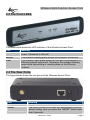
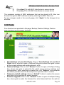
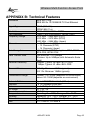
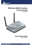
Wireless Multi-Function Access Point A02-AP1-W54 MANUAL A02-AP1-W54 _ME01 Where solutions begin Where solutions begin Wireless Multi-Function Access Point INDEX CHAPTER 1: INTRODUCTION 1.1 An Overview of the del Wireless Multi-Function Access Point 1.2 Package Contents 1.3 Wireless Multi-Function Access Point Features 1.4 System Requirements 1.5 Setup 1.6 Location 1 1 2 2 3 3 4 CHAPTER 2: USING WIRELESS ACCESS POINT 2.1 Cautions for using the Wireless Access Point 2.2 The Front LEDs 2.3 The Rear Ports 2.4 Cabling 5 5 6 6 7 CHAPTER 3: CONFIGURATION 3.1 Before Configuration 3.1.1 Windows 95/98/ME 3.1.2 Windows NT4.0 3.1.3 Windows 2000 3.1.4 Windows XP 3.2 Default Settings 3.2.1 Password 3.2.2 LAN WLAN 3.3 Accessing the Access Point Web Configurator 3.3.1 Navigating the Access Point Web Configurator 3.4 Wizard 3.5 Status 3.6 Basic Setting 3.6.1 Access Point Mode 3.6.2 AP Client Mode 3.6.3 WDS Mode 3.6.4 AP+WDS mode 3.6.5 Repeat Mode 3.7 IP Setting 8 8 9 10 11 12 13 13 13 13 14 15 17 18 19 21 23 29 31 33 Wireless Multi-Function Access Point 3.8 Advanced Setting 3.9 Security 3.10 Tools 34 35 36 APPENDIX A: TROUBLESHOOTING A.1 Using LEDs to Diagnose Problems A.1.1 LED Power A.1.2 LED LAN A.1.3 LED WLAN A.2 WEB A.3 Login A.4 FAQ 38 38 38 38 39 39 39 41 APPENDIX B: TECHNICAL FEATURES 45 APPENDIX C: SUPPORT 46 A02-AP1-W54_ME01 (V1.0 May2006) Wireless Multi-Function Access Point Copyright Statement No part of this publication may be reproduced, stored in a retrieval system, or transmitted in any form or by any means, whether electronic, mechanical, photocopying, recording or otherwise without the prior writing of the publisher. Windows™ 98SE/2000/ME/XP are trademarks of Microsoft® Corp. Pentium is trademark of Intel. All copyright reserved. The Atlantis Land logo is a registered trademark of Atlantis Land SpA. All other names mentioned mat be trademarks or registered trademarks of their respective owners. Subject to change without notice. No liability for technical errors and/or omissions. Wireless LAN, Health and Authorization for use Radio frequency electromagnetic energy is emitted from Wireless LAN devices. The energy levels of these emissions however are far much less than the electromagnetic energy emissions from wireless devices like for example mobile phones. Wireless LAN devices are safe for use frequency safety standards and recommendations. The use of Wireless LAN devices may be restricted in some situations or environments for example: ·On board of airplanes, or ·In an explosive environment, or ·In case the interference risk to other devices or services is perceived or identified as harmful In case the policy regarding the use of Wireless LAN devices in specific organizations or environments (e.g. airports, hospitals, chemical/oil/gas industrial plants, private buildings etc.) is not clear, please ask for authorization to use these devices prior to operating the equipment. Regulatory Information/disclaimers Installation and use of this Wireless LAN device must be in strict accordance with the instructions included in the user documentation provided with the product. Any changes or modifications made to this device that are not expressly approved by the manufacturer may void the user’s authority to operate the equipment. The Manufacturer is not responsible for any radio or television interference caused by unauthorized modification of this device, of the substitution or attachment. Manufacturer and its authorized resellers or distributors will assume no liability for any damage or violation of government regulations arising from failing to comply with these guidelines. Wireless Multi-Function Access Point CE Mark Warning This is a Class B product. In a domestic environment, this product may cause radio interference, in which case the user may be required to take adequate measures. CE in which Countries where the product may be used freely: Germany, UK, Italy, Spain, Belgium, Netherlands, Portugal, Greece, Ireland, Denmark, Luxembourg, Austria, Finland, Sweden, Norway and Iceland. France: except the channel 10 through 13, law prohibits the use of other channels. Federal Communication Commission Interference Statement This equipment has been tested and found to comply with the limits for a Class B digital device, pursuant to Part 15 of the FCC Rules. These limits are designed to provide reasonable protection against harmful interference in a residential installation. This equipment generates, uses and can radiate radio frequency energy and, if not installed and used in accordance with the instructions, may cause harmful interference to radio communications. However, there is no guarantee that interference will not occur in a particular installation. If this equipment does cause harmful interference to radio or television reception, which can be determined by turning the equipment off and on, the user is encouraged to try to correct the interference by one of the following measures: Reorient or relocate the receiving antenna. Increase the separation between the equipment and receiver. Connect the equipment into an outlet on a circuit different from that to which the receiver is connected. Consult the dealer or an experienced radio/TV technician for help. FCC Caution: To assure continued compliance, (example - use only shielded interface cables when connecting to computer or peripheral devices) any changes or modifications not expressly approved by the party responsible for compliance could void the user's authority to operate this equipment. This device complies with Part 15 of the FCC Rules. Operation is subject to the following two conditions: 1) This device may not cause harmful interference, and Wireless Multi-Function Access Point 2) This device must accept any interference received, including interference that may cause undesired operation. Wireless Multi-Function Access Point CHAPTER 1: Introduction Congratulations on your purchase of this IEEE 802.11g Wireless LAN Access Point. This manual helps to features the innovating wireless technology that can help you build a wireless network easily! This manual contains detailed instructions in operation of this product. Please keep this manual for future reference. With a WLAN (IEEE 802.11g) Access Point, a mobile computer can share data with another mobile computer in a wireless way. Easy-to-use utilities are bundled with WLAN Access Point for configuration and monitoring purposes. WLAN networking can wirelessly transmit and receive data, minimizing the need for wired connections, at a speed of up to Fifty-four megabit per second. With WLAN networking, you can locate your PC wherever you want without wires and cables. WLAN networking provides users with an access to real-time information anywhere in their organization. The mobility provides productivity and service, which are not available under wired networks. 1.1 An Overview of the del Wireless Multi-Function Access Point The device for a total freedom of movement without losing the connection. Easy to be installed and fast and flexible, with Wireless Multi-Function Access Point there is no more obligation for a fixed working place: you can easily work or navigate for fun from your own garden or in different rooms of your office, always in wireless connection. The Roaming function gives you a complete freedom of movement and two or more Wireless Multi-Function Access Point can serve wireless also large headquarters. A pair of Wireless Multi-Function APs operating under Bridge mode to act as the bridge that connect two Ethernet networks or Ethernet enabled clients together. Repeat Mode is able to extend the effective range and coverage of the wireless network. Last but not least the AP will be a wireless Ethernet adapter transforms any Ethernet-enabled devices to have the wireless function. Thanks to advanced security functions which are integrated and thanks to the troughput of the protocol IEE802.11G you are going to have a fast and flexible wireless net, hacker safe. The chipsets fully support Wi-Fi Protected Access (WPA/WPA2) and the IEEE802.11i draft security standards in hardware and high-speed encryption engines with no performance degradation. A02-AP1-W54 Pag. 1 Wireless Multi-Function Access Point 1.2 Package Contents Unpack the package and check all the items carefully. If any item contained is damaged or missing, please contact your local dealer as soon as possible. Also, keep the box and packing materials in case you need to ship the unit in the future. The package should contain the following items: Wireless Multi-Function Access Point 2 dBi Antenna CDRom with online manual Quick Start Guide (English, French, Italian) AC/DC power adapter (7.5 V, 1A) 1.3 Wireless Multi-Function Access Point Features Wireless Multi-Function Access Poin provides the following features: • IEEE 802.11g and IEEE 802.11b: With built-in 802.11g access point for extending the communication media to WLAN while providing the WEP and WPA for securing your wireless networks. • Wi-Fi Protected Access (WPA) and WEP encryption: Thanks to advanced security functions which are integrated and thanks to the troughput of the protocol IEE802.11G you are going to have a fast and flexible wireless net, hacker safe. The chipsets fully support Wi-Fi Protected Access (WPA) and the IEEE 802.11i draft security standards in hardware and high-speed encryption engines with no performance degradation. • WDS: A pair of Wireless Multi-Function APs operating under Bridge mode to act as the bridge that connect two Ethernet networks or Ethernet enabled clients together. Repeat Mode is able to extend the effective range and coverage of the wireless network. • 1 Antenna: 1 x 2 dBi Dipole detachable Antenna1 (SMA) • 1 port Fast Ethernet: A fast Ethernet 10/100Mbps port is supported in the LAN site and automatic switching between MDI and MDI-X for 10Base-T and 100Base-TX ports is supported. An Ethernet straight or cross-over cable can be used directly, this fast Ethernet switch will detect it automatically. • Mac Filtering (ACL): Access Control function allows clients whose MAC addresses in the list will be able to connect to this Access Point. • Web based GUI: supports web based GUI for configuration and management. It is user-friendly with an on-line help, providing necessary information and assist user timing. It also supports remote management capability for remote users to configure and manage this product. A02-AP1-W54 Pag. 2 Wireless Multi-Function Access Point • Firmware Upgrade : the device can be upgraded to the latest firmware through the WEB based GUI. 1.4 System Requirements Before installing the device, your PC should meet the following: Intel® Pentium®III 600Mhz or compatible processor with TCP/IP stack Iinternet Explorer V6.0 on Netscape V6.0 CDRom 1.5 Setup The setup of the Wireless Access Point can be performed using the following steps: • • • Visually inspect the Ethernet RJ45 port connector and make sure that it is fully plugged in to the system’s Ethernet switch/hub port. Fix the direction of the antennas. Try to place the AP in a position that can best cover your wireless network. Normally, the higher you place the antenna, the better the performance will be. The antenna’s position enhances the receiving sensitivity. Visually inspect if the Power Adapter was fully plugged to the device power jack. A02-AP1-W54 Pag. 3 Wireless Multi-Function Access Point 1.6 Location Locate an optimum location for the Wireless LAN Access Point (AP). The best place for your AP is usually the center of your wireless network, with line of sight to all of your mobile stations. Try to place the AP in a position that can best cover your wireless network. Normally, the higher you place the antenna, the better the performance will be. The antenna’s position enhances the receiving sensitivity. A02-AP1-W54 Pag. 4 Wireless Multi-Function Access Point CHAPTER 2: Using Wireless Access Point 2.1 Cautions for using the Wireless Access Point Do not place the Wireless Access Point under high humidity and high temperature. Do not use the same power source for Wireless Access Point with other equipment. Do not open or repair the case yourself. If the Wireless Access Point is too hot, turn off the power immediately and have a qualified serviceman repair it. Place the Wireless Access Point on a stable surface. Only use the power adapter that comes with the package. Do NOT upgrade firmware on any Atlantis Land product over a wireless connection. Failure of the device may result. Use only hard-wired network connections. A02-AP1-W54 Pag. 5 Wireless Multi-Function Access Point 2.2 The Front LEDs The table below shows the LED Indicator of the Wireless Access Point. LED Meaning This indicator lights green when the Access Point receives POWER power. Otherwise, it turns off. The indicator blinking green whiles the wireless LAN activity. WLAN The indicator lights green when the LAN port is connected to a LAN Ethernet network successful. Otherwise, the indicator blinking green while transmitting or receiving data on the Ethernet network. 2.3 The Rear Ports The figure below shows the rear panel of the Wireless Access Point. Port ANTENNA RESET Meaning One external dipole antenna. The Reset function is to reset the setting back to factory default setting, once you press the “RESET” button more than 5 seconds. A02-AP1-W54 Pag. 6 Wireless Multi-Function Access Point LAN POWER Ethernet port with 10/100Mbps Fast Ethernet connections, connect this port to switch/hub. Connect the Power Adapter DC plug to the AP’s power jack. 2.4 Cabling Connect to the Switch/Hub • Plug in one end of the RJ45 network cable to the Switch/Hub port • Plug in the other end of the RJ45 network cable to the Wireless Access Point Check the installation The LEDs of the Access Point are clearly visible and the status of the network link can be seen instantly: • • With the power source on, once the device is connected, the Power, LAN and WLAN port LEDs will light up indicating a normal status. If the LAN Port’s Link indicator does not light up then check the RJ-45 cable if it is firmly feed to the RJ45 port, while the LAN is link up to the Switch/Hub, the LAN port’s LED will light up. A02-AP1-W54 Pag. 7 Wireless Multi-Function Access Point CHAPTER 3: Configuration The Wireless Access Point has a Web GUI interface for the configuration. The AP can be configured through the Web Browser. A network manager can manage, control and monitor the AP from the local LAN. This section indicates how to configure the AP to enable its functions. 3.1 Before Configuration This section describes the configuration required by LAN-attached PCs that communicate with the Wireless Access Point, either to configure the device or for network access. These PCs must have an Ethernet interface (or wireless adapter) installed properly, be connected to the Wireless Access Point either directly or through an external repeater hub or by wireless, and have TCP/IP installed and configured with a fixed IP address that must be in the same subnet of the Wireless Access Point. The default IP address of the Wireless Access Point is 192.168.1.1 and subnet mask is 255.255.255.0. Please follow the steps below for PC’s network environment installation. First of all, please check your PC’s network components. The TCP/IP protocol stack and Ethernet network adapter must be installed. If not, please refer to MS Windows related manuals. Any TCP/IP capable workstation can be used to communicate with or through the Wireless Access Point to configure other types of workstations, please consult the manufacturer’s documentation. A02-AP1-W54 Pag. 8 Wireless Multi-Function Access Point 3.1.1 Windows 95/98/ME 1. Go to Start / Settings / Control Panel. In the Control Panel, double-click on Network and choose the Configuration tab. 2. Select TCP / IP -> NE2000 Compatible, or the name of any Network Interface Card (NIC) in your PC. 3. Click Properties. 4. Select the IP Address tab. In this page, click the Specify an IP address radio button (EG IP=192.168.1.2 and subnet Mask=255.255.255.0). A02-AP1-W54 Pag. 9 Wireless Multi-Function Access Point 3.1.2 Windows NT4.0 1. Go to Start / Settings / Control Panel. In the Control Panel, doubleclick on Network and choose the Protocols tab. 2. Select TCP/IP Protocol and click Properties. 3. Select the IP Address tab. In this page, click the Specify an IP address radio button (EG IP=192.168.1.2 and subnet Mask=255.255.255.0). A02-AP1-W54 Pag. 10 Wireless Multi-Function Access Point 3.1.3 Windows 2000 1. Go to Start / Settings / Control Panel. In the Control Panel, double-click on Network and Dial-up Connections. 2. Double-click LAN Area Connection. 3. In the LAN Area Connection Status window, click Properties. 4. Select Internet Protocol (TCP/IP) and click Properties. 5. Select Use the Following IP Address (EG IP=192.168.1.2 and subnet Mask=255.255.255.0). 6. Click “OK” to finish the configuration. A02-AP1-W54 Pag. 11 Wireless Multi-Function Access Point 3.1.4 Windows XP 1. Go to Start / Control Panel (in Classic View). In the Control Panel, doubleclick on Network Connections. 2. Double-click Local Area Connection 3. In the LAN Area Connection Status window, click Properties. 4. Select Internet Protocol (TCP/IP) and click Properties. 5. Select the Use the following IP address radio buttons IP=192.168.1.2 (EG and subnet Mask=255.255.255.0). 6. Click “OK” to finish the configuration. A02-AP1-W54 Pag. 12 Wireless Multi-Function Access Point 3.2 Default Settings Before configuring the Wireless AP through WLAN, make sure that the SSID, Channel and the WEP was set properly. The default setting of the Wireless AP that you will use: User: admin Password: admin IP Address: 192.168.1.1 Subnet Mask: 255.255.255.0 Wep Encryption: disable SSSID: default Channel:6 3.2.1 Password When there is a screen needs to enter the Network password, it means that there is a password settle, type in the password you entered before. 3.2.2 LAN WLAN The parameters of LAN and WLAN ports are pre-set in the factory. The default values are shown below. LAN WLAN 192.168.1.1 IP address Channel=6 SSID=default 255.255.255.0 Subnet Mask Encryption=none 3.3 Accessing the Access Point Web Configurator Before you configure this device, note that when the AP is configured through an Ethernet connection, make sure the manager PC must be set on same the IP network. For example, when the default network address of the default IP address of the AP is 192.168.1.1, then the manager PC should be set at 192.168.1.x (where x is a number between 2 and 254), and the default subnet mask is 255.255.255.0. Open Internet Explorer 5.0 or above Web browser. Enter IP address http://192.168.1.1 (the factory-default IP address setting) to the address location. A02-AP1-W54 Pag. 13 Wireless Multi-Function Access Point When there is a screen needs to enter the User name and Password, both of the default Username and Password is “admin”. Click OK. The screen will show the station summary of the AP when you login to the AP. 3.3.1 Navigating the Access Point Web Configurator The screen will show the status of the AP when you login to the AP. There are seven main functions included in the top side of the main screen: • • • • • • • Wizard Status Basic Setting IP Setting Advanced Setting Security Tools Point the selections in the top side of the menu screen. A02-AP1-W54 Pag. 14 Wireless Multi-Function Access Point 3.4 Wizard Setup wizard is provided as the part of the web configuration utility. User can simply follow the step-by-step process to get Access Point configuration ready to run in 4 easy steps by clicking on the “Wizard” button on the function menu. The following screen will appear. Please click “Next” to continue. User can change the password and then click “Next” to continue. Please type the name of SSID and select the Channel. Then, click “Next” to continue. A02-AP1-W54 Pag. 15 Wireless Multi-Function Access Point If user wants to enable WEP, please click “Enabled”. Then, select the key size of WEP encryption and enter the key value in the key text box. Please click “Next” to continue. The Setup wizard is now completed. The new settings will be effective after the Access Point restarted. Please click “Restart” to reboot the Access Point. If user does not want to make any changes, please click “exit” to quit without any changes. User also can go back to modify the setting by clicking “back”. A02-AP1-W54 Pag. 16 Wireless Multi-Function Access Point 3.5 Status This page as below shows the following information. Firmware Version: Shows the current firmware version and released date code. LAN: Shows the Mac address, IP address (default: 192.168.1.1), Subnet Mask, Gateway Address. The current LAN traffic calculated in terms of number of packets sent and received by AP through wired connection is also displayed. Wireless: Shows the Mac address, current SSID, the status of Encryption Function (Enable or Disable), the current using channel. The current wireless traffic calculated in terms of number of packets sent and received by AP through wireless communication is also displayed. A02-AP1-W54 Pag. 17 Wireless Multi-Function Access Point View Log: Once clicked, the page will change to login page. The login page records every event and the time that it happens. NOTE: User may clear the entries recorded in the log by clicking the Clear Log button, and refresh the screen to show the latest log entries by clicking the Refresh button. 3.6 Basic Setting This is the page allow user to change the access point settings. AP Name: The name of the AP, which can be used to identify the Access Point among the all the Access Points in the wireless network. Mode: The WLAN AP supports five operation mode for Access Point, AP Client, WDS (Wireless Distribution System), AP+WDS and Repeater mode. A02-AP1-W54 Pag. 18 Wireless Multi-Function Access Point 3.6.1 Access Point Mode Configure the AP to Access Point mode; with this mode, WLAN clients can access LAN or other WLAN clients through this AP. Channel: The channel that AP will operate in. User can select the channel range from 1 to 11 for North America (FCC) domain, 1 to 13 for European (ETSI) domain and 1 to 14 for Japanese domain. SSID: Service Set Identifier, which is a unique name shared among all clients and nodes in a wireless network. The SSID must be identical for each clients and nodes in the wireless network. Authentication Type: The authentication type default is set to Open system. There are six options: Open system; Shared Key; WPA-PSK, WPA2-PSK, WPA and WPA2. User may want to set to Shared Key when the clients and AP in the same wireless network enable the encryption. All the nodes and hosts on the network must use the same authentication type. WEP Key: To disable WEP security, click on the “Disable” option. To enable WEP security, there are 2 types to select – 64bits and 128 bits. When it is selected, the key value must be entered in ASCII or HEX format. Note: When the WEP security is enabled, all the wireless clients that wish to connect to the Access Point must also have WEP enabled with the identical WEP Key value entered. A02-AP1-W54 Pag. 19 Wireless Multi-Function Access Point WEP is not completely secure. If possible please use WPA-PSK. WPA-PSK / WPA2-PSK: If WPA-PSK or WPA2-PSK is selected, user needs to set the key in the passphrase field as the below screen. The key length should be 8 characters at least. WPA / WPA2: If WPA or WPA2 is selected, the below screen is shown. Please set the length of the encryption key and the parameters for the RADIUS server. 1. RADIUS Server 1: Enter the IP address of and the Port used by the Primary Radius Server, enter the Shared Secret, which is used by the Radius Server. 2. RADIUS Server 2(optional): Enter the IP address of and the Port used by the Secondary Radius Server, enter the Shared Secret, which is used by the Radius Server. Apply: For the changes made to any of the items above to be effective, click “Apply”. The new settings are now been saved to Access Point and will be effective once the Access Point restarts. The range of radio frequencies used by IEEE 802.11g wireless devices is called a “channel”. Channels available depend on your geographical area. You may have a choice of channels (for your region) so you should use a different channel than an adjacent AP (access point) to reduce interference. Interference occurs when radio signals from different access points overlap causing interference and degrading performance. Adjacent channels partially overlap however. To avoid interference due to overlap, your AP should be on a channel at least five channels away from A02-AP1-W54 Pag. 20 Wireless Multi-Function Access Point a channel that an adjacent AP is using. For example, if your region has 11 channels and an adjacent AP is using channel 1, then you need to select a channel between 6 or 11. 3.6.2 AP Client Mode Configure the AP to AP Client mode; the AP will be a wireless Ethernet adapter transforms any Ethernet-enabled devices to have the wireless function. SSID: Service Set Identifier, which is a unique name shared among all clients and nodes in a wireless network. The SSID must be identical for each clients and nodes in the wireless network. Site Survey: This button allows user to enable the Site Survey function to scan for the available wireless network (wireless clients and Access Points) and establish wireless communications with one. Selected one of them in list to establish communications and click “Connect” button. Authentication Type: The authentication type default is set to Open system. There are four options: Open system; Shared Key; WPA-PSK and WPA2PSK. User may want to set to Shared Key when the clients and AP in the same wireless network enable the WEP encryption. All the nodes and hosts on the network must use the same authentication type. WEP Key: To disable WEP security, click on the “Disable” option. To enable WEP security, there are 2 types to select – 64bits and 128 bits. When it is selected, the key value must be entered in ASCII or HEX format. A02-AP1-W54 Pag. 21 Wireless Multi-Function Access Point Note: When WEP security is enabled, all the wireless clients that wish to connect to the Access Point must also have WEP enabled with the identical WEP Key value entered. WPA-PSK / WPA2-PSK: If WPA-PSK or WPA2-PSK is selected, user needs to set the key in the passphrase field as the below screen. The key length should be 8 characters at least. Apply: For the changes made to any of the items above to be effective, click “Apply”. The new settings are now been saved to Access Point and will be effective once the Access Point restarts. Note: For entering to the Web Setting page after changing to AP Client mode, change your PC/Notebook IP address to 192.168.1.x. After changing your IP address, type 192.168.1.1 on the Web browser to enter the setting of this Wireless AP. A02-AP1-W54 Pag. 22 Wireless Multi-Function Access Point 3.6.3 WDS Mode With WDS (Wireless Distribution System) mode, user can use wireless media to communicate two or more LANs through the AP with WDS mode, all of the LAN will be combined in the WDS group, for example: • Single WDS group application: When there are three APs joined to the WDS group, one of the AP in WDS mode will be the Master, the other two APs will be the Slave, all of the APs in the WDS group must use the same wireless channel and the same security setting, the Master need to fill all the Slave’s MAC address in the “Remote AP Mac” list, and the Slave need to fill the Master’s MAC address in the “Remote AP Mac” list, the maximum of one Master can join eight Slave to be one WDS group. In this example, LAN-A can communicate with LAN-B and LAN-C, and LAN-B can communicate with LAN-C through the AP-A. All of LANs will be at the same LAN environment coming through LAN-A. A02-AP1-W54 Pag. 23 Wireless Multi-Function Access Point A02-AP1-W54 Pag. 24 Wireless Multi-Function Access Point • Multiple WDS group application: When there are five APs to be join into two separated WDS group, the member of WDS group 1 is AP-A, AP-B and AP-C, and member of the WDS group 2 is AP-C, AP-D and AP-E, the AP-C will join both of WDS group 1 and WDS group 2, each WDS Group 1 will be one master and the other will be slave. The AP-A and AP-C will be both as a Master AP for both WDS Groups, the AP-A represent for the master of WDS Group 1, the AP-C represent for the master of the WDS Group 2 and at the same time AP-C will be the slave of WDS Group 1, so all of the APs in the two WDS groups must use the same wireless channel and same security, the Master need to fill all of Slave’s MAC address in the “Remote AP Mac” list, and the Slave need to fill the Master’s MAC address in the “Remote AP Mac” list, maximum allow one Master can be join eight Slaves to be one WDS group. In this example, LAN-A can communicate with LAN-B and LAN-C, and LAN-B can communicate with LAN-C through the AP-A. LAN-B will have the same LAN environment coming through LAN-A. LAN-E can communicate with LAN-B and LAN-D, LAN-E can communicate with LAN-D through AP-C, LAN-E can communicate with LAN-B through APC and AP-A, LAN-E will have the same LAN environment coming through A02-AP1-W54 Pag. 25 Wireless Multi-Function Access Point LAN-A. A02-AP1-W54 Pag. 26 Wireless Multi-Function Access Point A02-AP1-W54 Pag. 27 Wireless Multi-Function Access Point A02-AP1-W54 Pag. 28 Wireless Multi-Function Access Point 3.6.4 AP+WDS mode With WDS+AP mode, user can use wireless media to communicate two or more LANs through the AP with WDS+AP mode, all of LAN will be combined in the WDS group and WLAN client can access to the AP with AP+WDS mode. Please refer the AP mode and WDS mode for detail configuration. A02-AP1-W54 Pag. 29 Wireless Multi-Function Access Point A02-AP1-W54 Pag. 30 Wireless Multi-Function Access Point 3.6.5 Repeat Mode Configure the AP to Repeater mode; the AP will be a wireless LAN repeater that will be extended the WLAN coverage range. SSID: Service Set Identifier, which is a unique name shared among all clients and nodes in a wireless network. The SSID must be identical for each clients and nodes in the wireless network. Site Survey: This button allows user to enable the Site Survey function to scan for the available wireless network (wireless clients and Access Points) and establish wireless communications with one. Selected one of them in list to establish communications and click “Connect” button. Authentication Type: The authentication type default is set to Open system. There are four options: Open system; Shared Key; WPA-PSK and WPA2PSK. User may want to set to Shared Key when the clients and AP in the same wireless network enable the WEP encryption. All the nodes and hosts on the network must use the same authentication type. WEP Key: To disable WEP security, click on the “Disable” option. To enable WEP security, there are 2 types to select – 64bits and 128 bits. When it is selected, the key value must be entered in ASCII or HEX format. Note: When WEP security is enabled, all the wireless clients that wish to connect to the Access Point must also have WEP enabled with the identical WEP Key value entered. A02-AP1-W54 Pag. 31 Wireless Multi-Function Access Point WPA-PSK / WPA2-PSK: If WPA-PSK or WPA2-PSK is selected, user needs to set the key in the passphrase field as the below screen. The key length should be 8 characters at least. Apply: For the changes made to any of the items above to be effective, click “Apply”. The new settings are now been saved to Access Point and will be effective once the Access Point restarts. You must make sure that the SSID, Encryption and Channel is set the same as that AP you wish to connect. When WDS is enable only WEP ecryption is supported. A02-AP1-W54 Pag. 32 Wireless Multi-Function Access Point 3.7 IP Setting This page allows user to configure the IP and DHCP settings of the Access Point. The default IP address of this access point is 192.168.1.1 with the subnet mask of 255.255.255.0. User can type in other values for IP Address, Subnet Mask and Gateway and click “Apply” button for the changes to be effective. User can also set the Access Point to obtain the IP from a DHCP server, but it is not recommended. Select the option “Obtain IP Automatically” and click “Apply” button for the changes to be effective. DHCP Server: It is not recommended to enable the DHCP Server if user has a DHCP server running in LAN network because it probably will cause possible the conflict of IP assignment. Enable the DHCP server function by selecting the option “On”, and enter the IP range. DNS Server: Type up to DNS IP address in the text boxes. Your ISP will provide you with this information. Click “Apply” for the changes to be effective. A02-AP1-W54 Pag. 33 Wireless Multi-Function Access Point 3.8 Advanced Setting This page contains configurations for advanced users, which the change reflects the wireless performance and operating modes. Beacon Interval: To set the period of time in milliseconds that AP sends out a beacon. Default is 100 milliseconds. RTS Threshold: To set the size of RTS/CTS packet size. Default is 2432 bytes. Fragmentation Threshold: To set the number of bytes used for the fragmentation boundary for directed messages. Default is 2436 bytes. DTIM Interval: This value indicates the interval of the Delivery Traffic Indication Message (DTIM). A DTIM field is a countdown field informing clients of the next window for listening to broadcast and multicast messages. When the access point has buffered broadcast or multicast messages for associated clients, it sends the next DTIM with a DTIM interval value. Access point clients hear the beacons and awaken to receive the broadcast and multicast messages. SSID Broadcast: While SSID Broadcast is enabled, all wireless clients will be able to communicate with the access point. For secure purpose, user may want to disable SSID broadcast to allow only those wireless clients with the AP SSID to communicate with the access point. A02-AP1-W54 Pag. 34 Wireless Multi-Function Access Point Mode Setting: To setting the AP operation mode for 802.11g only or 802.11b/802.11g mix mode TX Rates: Select one of the wireless communications transfer rates, measured in megabytes per second, based upon the speed of wireless adapters connected to the WLAN. 3.9 Security This page is where user configures the security features supported by this Access Point. Password: Allow user to change the new login password. Here are the necessary steps: 1. Enter the new password in the “AP Password New:” field. 2. Enter the new password again in the “Confirm” field. 3. Click “Apply” MAC Filter: MAC Filter function controls the MAC of the network devices that are listed in this table for access authorization or denial. There have three choices: 1. Disable MAC Filters A02-AP1-W54 Pag. 35 Wireless Multi-Function Access Point 2. 3. Only allow PCs with MAC listed below to access device Only deny PCs with MAC listed below to access device The maximum number of MAC addresses that can be stored is 50. User can browse through the MAC address saved by selecting the MAC Filter List. For any changes made in the security page, click “Apply” for the changes to be effective. 3.10 Tools Four functions are provided in this page, Backup, Restore Settings, Restore default settings and Firmware Upgrade. Save Settings to Local Hard Drive: Click on “Save Settings to Local Hard Drive” button, which will open a FileSave Dialog box, where user gets to save all the current settings and configurations to a file. Restore Settings: Click on the “Browse” button to open a FileOpen Dialog box, where user gets to select the file, which saves previous settings and configurations. Upon selecting the saved file, click “Restore” and complete the restore process when the access point re-operates after it restarts. Restore to default settings: Click on “Default” button to restore the access point back to its manufacture default settings. Firmware Upgrade: Click on the “Browse” button to open a FileOpen Dialog box, where gets to select the firmware file, which download from the web for A02-AP1-W54 Pag. 36 Wireless Multi-Function Access Point the latest version. Upon selecting the firmware file, click “Upgrade” and complete the firmware upgrade process when the Access Point re-operates after it restarts. Do NOT upgrade firmware on any Atlantis Land product over a wireless connection. Failure of the device may result. Use only hard-wired network connections. After upgrading you must reset the router to factory default settings, then manually re-enter your settings. Please pay attention. In case electrical shutdown, during this procedure, this product could be not usable. When uploading software to theWireless Multi-Function Access Point, it is important not to interrupt the Web browser by closing the window or loading a new page. If the browser is interrupted, it may corrupt the software A02-AP1-W54 Pag. 37 Wireless Multi-Function Access Point APPENDIX A: Troubleshooting This chapter covers potential problems and the corresponding remedies. A.1 Using LEDs to Diagnose Problems The LEDs are useful aides for finding possible problem causes. A.1.1 LED Power The PWR LED on the front panel does not light up. CORRECTIVE ACTION Steps Make sure that the Wireless Access Point’s power adaptor is 1 connected to the Access Point and plugged in to an appropriate power source. Use only the supplied power adaptor. Check that the Wireless Access Point and the power source 2 are both turned on and the Wireless Access Point is receiving sufficient power. If the error persists, you may have a hardware problem. In this 3 case, you should contact your vendor. A.1.2 LED LAN The LAN LED on the front panel does not light up. CORRECTIVE ACTION Steps Check the Ethernet cable connections between the Access 1 Point and the computer or hub. Check for faulty Ethernet cables. 2 Make sure your computer’s Ethernet card is working properly. 3 If these steps fail to correct the problem, contact your local 4 distributor for assistance. A02-AP1-W54 Pag. 38 Wireless Multi-Function Access Point A.1.3 LED WLAN The WLAN LED on the front panel does not light up. CORRECTIVE ACTION Steps Press the “Reset” button on the rear panel of the AP, to set 1 back to factory default setting. Please unplug AC Adaptor and replug-it. 2 If these steps fail to correct the problem, contact your local 3 distributor for assistance. A.2 WEB I cannot access the web configurator. CORRECTIVE ACTION Steps Make sure you are using the correct IP address of the 1 Wireless Multi-Function Access Point. Check the IP address of the Access Point (192.168.1.1). 2 Check Mac Filtering (on Security). Access Control function allows clients whose MAC addresses in the list will be able to connect to this Access Point. When this function is activate, there is no wireless clients will be able to connect to the Access Point unless they are listed in the Access Control list. Press the “Reset” button on the rear panel of the AP, to set 3 back to factory default setting. The web configurator does not display properly. CORRECTIVE ACTION Steps Make sure you are using Internet Explorer 5.0 and later 1 versions. Delete the temporary web files and log in again. 2 In Internet Explorer, click Tools, Internet Options and then click the Delete Files ... button. When a Delete Files window displays, select Delete all offline content and click OK. (Steps may vary depending on the version of your Internet browser.) A.3 Login If you forget the password to log in CORRECTIVE ACTION Steps 1 The Reset function is to reset the setting back to factory default setting, once you press the “RESET” button within 10 A02-AP1-W54 Pag. 39 Wireless Multi-Function Access Point seconds, the LED of the WLAN will turn off. And when the Access Point is ready, the WLAN LED will start blinking. And the other function is when the AP is locked, press the reset button to unlock it. 2 Before configurating thisWireless Multi-Function Access Point, you need to know the following default settings. Username: admin Password : admin IP Address : 192.168.1.1 Subnet Mask : 255.255.255.0 Wireless: SSSID= default, Channel=6, WEP=disable A02-AP1-W54 Pag. 40 Wireless Multi-Function Access Point A.4 FAQ Question Answer Question Answer Can I run an application from a remote computer over the wireless network? This will depend on whether or not the application is designed to be used over a network. Consult the application’s user guide to determine if it supports operation over a network. Can I play computer games with other members of the wireless network? Yes, as long as the game supports multiple players over a LAN (local area network). Refer to the game’s user guide for more information. Question Answer What is Spread Spectrum? Spread Spectrum technology is a wideband radio frequency technique developed by the military for use in reliable, secure, mission-critical communications systems. It is designed to trade off bandwidth efficiency for reliability, integrity, and security. In other words, more bandwidth is consumed than in the case of narrowband transmission, but the trade-off produces a signal that is, in effect, louder and thus easier to detect, provided that the receiver knows the parameters of the spread-spectrum signal being broadcast. If a receiver is not tuned to the right frequency, a spread-spectrum signal looks like background noise. There are two main alternatives, Direct Sequence Spread Spectrum (DSSS) and Frequency Hopping Spread Spectrum (FHSS). Question What is DSSS? What is FHSS? And what are their differences? Frequency-Hopping Spread-Spectrum (FHSS) uses a narrowband carrier that changes frequency in a pattern that is known to both transmitter and receiver. Properly synchronized, the net effect is to maintain a single logical channel. To an unintended receiver, FHSS appears to be short-duration impulse noise. Direct-Sequence SpreadSpectrum (DSSS) generates a redundant bit pattern for each bit to be transmitted. This bit pattern is called a chip (or chipping code). The longer the chip, the greater the probability that the original data can be recovered. Even if one or more bits in the chip are damaged during transmission, statistical Answer A02-AP1-W54 Pag. 41 Wireless Multi-Function Access Point techniques embedded in the radio can recover the original data without the need for retransmission. To an unintended receiver, DSSS appears as low power wideband noise and is rejected (ignored) by most narrowband receivers. Question Answer Would the information be intercepted while transmitting on air? WLAN features two-fold protection in security. On the hardware side, as with Direct Sequence Spread Spectrum technology, it has the inherent security feature of scrambling. On the software side, WLAN offers the encryption function (WEP) to enhance security and access control. Question Answer What is WEP? WEP is Wired Equivalent Privacy, a data privacy mechanism based on a 64-bit or 128-bit shared key algorithm, as described in the IEEE 802.11 standard. Question Answer What is infrastructure mode? When a wireless network is set to infrastructure mode, the wireless network is configured to communicate with a wired network through a wireless access point. Question Answer What is roaming? Roaming is the ability of a portable computer user to communicate continuously while moving freely throughout an area greater than that covered by a single access point. Before using the roaming function, the workstation must make sure that it is the same channel number with the access point of dedicated coverage area. Question Answer What is ISM band? The FCC and their counterparts outside of the U.S. have set aside bandwidth for unlicensed use in the ISM (Industrial, Scientific and Medical) band. Spectrum in the vicinity of 2.4 GHz, in particular, is being made available worldwide. This presents a truly revolutionary opportunity to place convenient high-speed wireless capabilities in the hands of users around the globe. A02-AP1-W54 Pag. 42 Wireless Multi-Function Access Point Question Answer What is the IEEE 802.11g standard? Approved in June, 2003 as an IEEE standard for wireless local area networks (WLANs), 802.11g offers wireless transmission over relatively short distances at up to 54 megabits per second (Mbps) compared with the 11 megabits per second of the 802.11b (Wi-Fi) standard. Like 802.11b, 802.11g operates in the 2.4 GHz range and is thus compatible with it. A02-AP1-W54 Pag. 43 Wireless Multi-Function Access Point A02-AP1-W54 Pag. 44 Wireless Multi-Function Access Point APPENDIX B: Technical Features Standards IEEE 802.11b/g IEEE 802.3u 10/100BASE-TX Fast Ethernet Signal Type: DSSS (802.11b) OFDM (802.11g) QPSK / BPSK / CCK / OFDM Power, LAN (Link/Activity), WLAN (Link) 2412 MHz ~ 2462 MHz (FCC) 2412 MHz ~ 2472 MHz (ETSI) 2400 MHz ~ 2484 MHz (Japan) 1 ~ 11 Channels (FCC) 1 ~ 13 Channels (ETSI) 1 ~ 14 Channels (Japan) 64 bit / 128 bit WEP Encryption, WPA, WPA2, WPA-PSK, WPA2-PSK Fast Ethernet: 10/100Mbps Wireless: Up to 54Mbps (with Automatic Scale Back) 54Mbps: Typical -68 dBm @10% PER 11Mbps: Typical -81 dBm @8% PER Modulation: LED Indicators: Frequency Range Channel: Data Encryption: Data Transfer Rate Receiver Sensitivity Transmit Power 802.11g: Minimum 13dBm typically 802.11b: Minimum 15dBm typically Transmission Range: Outdoor: 100~300M (depends on environment) Indoor: 50~100M (depends on environment) Network Cables Interface Antenna: DC inputs Power Consumption Temperature Humidity Dimensions EMI 2-pair UTP/STP Cat. 3,4,5 (100 m) 1 x 10/100Mbps RJ45 port 1 x 2 dBi Dipole Antenna DC 7.5V /1A 4.2W (Max) Operating: 0 ~ 40 oC, Storage: -10 ~ 70 oC Operating: 10% ~ 90%, Storage: 5% ~ 90% 140 x 98 x 30 mm (W x H x D) without Antenna FCC Class B, CE Mark B A02-AP1-W54 Pag. 45 Wireless Multi-Function Access Point APPENDIX C: Support If you have any problems with the Wireless Access Point, please consult this manual. If you continue to have problems you should contact the dealer where you bought this device. If you have any other questions you can contact the Atlantis Land company directly at the following address: Atlantis Land SpA Viale De Gasperi 122 20017 Mazzo di Rho(MI) ITALY Tel: 039.02.93907634(help desk) Fax: 039.02.93906161 Email: [email protected] or [email protected] WWW: http://www.atlantisland.it or www.atlantis-land.com A02-AP1-W54 Pag. 46