1
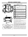
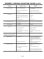
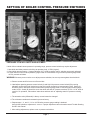
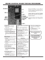
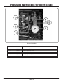
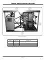
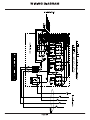
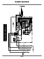
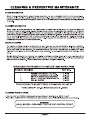
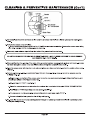
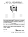
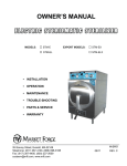
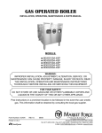
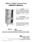
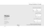
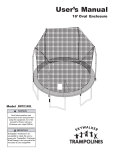
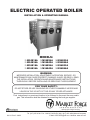
ELECTRIC OPERATED BOILER
INSTALLATION & OPERATING MANUAL
m
m
m
m
M24E18A
M24E36A
M36E18A
M36E36A
MODELS:
m
m
m
m
M24E24A
M24E42A
M36E24A
M36E42A
m
m
m
m
M24E32A
M24E48A
M36E32A
M36E48A
WARNING:
IMPROPER INSTALLATION, ADJUSTMENT, ALTERATION, SERVICE OR
MAINTENANCE CAN CAUSE PROPERTY DAMAGE, INJURY OR DEATH. READ
THE INSTALLATION, OPERATION AND MAINTENANCE INSTRUCTIONS
THOROUGHLY BEFORE INSTALLING OR SERVICING THIS EQUIPMENT.
FOR YOUR SAFETY:
DO NOT STORE OR USE GASOLINE OR OTHER FLAMMABLE VAPORS AND
LIQUIDS IN THE VICINITY OF THIS OR ANY OTHER APPLIANCE.
Post instructions in a prominent location to be followed in the event the user smells
gas. This information shall be obtained by consulting the local gas supplier.
An Employee Owned Company
Printed in U.S.A.
S-3112 Rev.C 08/05
35 Garvey Street l Everett l MA l 02149
Tel: (617) 387-4100 l Fax: 1-800-227-2659 (Ex. MA) l (617) 387-4456 (MA and Overseas)
E-Mail: [email protected] l Website: www.mfii.com
INTRODUCTION
TO THE KITCHEN MANAGER:
1. Read this manual carefully and in its entirety. Contact Market Forge Ind., Inc. for clarification if necessary.
2. Protect your kitchen personnel from scalding and other serious injury by providing training programs to acquaint all
equipment operators with the correct and safe methods of operation.
3. Operators must be made aware of the consequences of misuse. Steam producing equipment, no matter who the
manufacturer, is inherently dangerous when misused. The possibility of serious scalding always exists, the careless
and/or untrained operator will be injured.
4. This equipment must be maintained according to the guidelines in this manual (see "maintenance"). Lack of maintenance
will lead to a potentially hazardous condition and possible liability. Operators should report any equipment malfunction
immediately and steps must be taken to correct the problem before further use of the equipment is allowed.
5. Keep this manual for daily reference.
INTRODUCTION:
Market Forge, in the interest of both cost and efficiency has designed these steam boilers with the latest automatic
controls in order to make it easier for the operator to use and maintain this equipment. Standard components are
utilized on all models unless variances in size or capacity dictate a divergence from this policy for more efficiency of
operation. This parts and service manual is written and illustrated to cover all steam boiler equipment that uses gas
as a source of fuel other than those which have been custom designed under special order.
HOW TO USE THIS MANUAL:
The pictures of components are aids to the identification, disassembly and assembly of parts. The parts listing
provides information necessary for the ordering of replacement parts (proper part names and part numbers). When
requesting parts or service; always furnish the model and serial number of your complete unit, this will indicate to
Market Forge Service Personnel the type of boiler that you have. This information can be found on the nameplate
attached to the boiler frame.
THEORY OF OPERATION FOR ELECTRIC BOILER:
An explanation of how the control system operates on automatic electric boilers follows:
With the boiler filled with water to the proper level and the fuel switch is turned ON, the contactors will pull in and
permit the completion of the electric circuit to the heating element. When the boiler builds to its set pressure, the
pressure switch opens. This will open the circuit to the coil in the contactor, which in turn will drop put the contacts in
the contactor and shut off the electricity. As the pressure in the boiler drops the pressure control switch will again
complete the circuit and build the boiler back to its set pressure. To stop all steam generation place the fuel switch to
the OFF position.
ii
INSTALLATION INSTRUCTIONS
ELECTRIC OPERATED BOILERS
MODELS:
m M24E18A
m M24E36A
m M36E18A
m M36E36A
m M24E24A
m M24E42A
m M36E24A
m M36E42A
m M24E32A
m M24E48A
m M36E32A
m M36E48A
WARNING: READ THIS BEFORE OPEING THE SHIPPING CONTAINERS!
CAUTION: BE SURE TO READ:
DO NOT AT ANY TIME LAY THE EQUIPMENT DOWN ON ITS BACK, SIDE, TOP OR FRONT. Doing so may damage the
equipment and invalidate the warranty.
RECEIVING INSTRUCTIONS:
Inspect the equipment before signing the bill of lading. The equipment supplied was tested and inspected before shipment.
The carrier accepted it as complete and without damage.
This merchandise became your property when it was accepted by the carrier at the factory. Market Forge cannot assume
responsibility for loss or damage during transit.
For this reason, you should immediately inspect for visible and concealed damage or shortages before signing for shipment
as follows:
1. Count the number of cartons and packages received to be sure they coincide with the bill of lading.
2. Visually check all cartons for external damage.
3. Remove all cartons from their skids to examine equipment for concealed damage. The carton is nailed and strapped to
the skid. It will be necessary to cut the straps and pry off the container.
4. After inspection, replace the cartons over the equipment on the skids to protect and secure the equipment until it is ready
for installation.
5. Sign for shipment if all is in order. Note shortages, external and concealed damage, if any, on the bill of lading before
accepting a partial or damaged shipment.
6. If necessary, contact the carrier immediately to file a claim. All claims must be filed by the receiver.
7. Do not remove the cartons or the skids from the cooking equipment until the unit has been transported through the
building to the actual set-up location. The cartons should remain on the equipment as protection against dents and
scratches.
INSTALLING LEGS:
Some models are shipped without legs. A separate carton will contain the legs. If your model is received this way, be sure
to follow the installation instruction sheet packed with the legs.
LEVELING:
In order for the boiler to drain correctly, it is important to use a level on cabinet top both left and right and front-to-back. If
not level, adjust feet. On compartment cookers, check the interior shelves for level condition.
Page 1
SERVICE CONNECTIONS
SERVICE CONNECTIONS
Electrically Operated
EP
Power Supply - Use wire suitable for at least 90°C.
Nominal amp per line wire:
Volts
18KW
24KW 32KW 36KW 42KW
1ph 3ph 3ph
3ph
3ph
3ph
208 (197-219) 86
50
6
89
100
117
240 (220-240) 75
32
60
77
91
480 (360-500) 36
22
32
39
47
-
48KW
3ph
116
58
Details of other electrical systems available upon request.
CW1 Cold Water - 3/8" (10mm) NPT for cold water to boiler.
Cold water lines will have a maximum of 50 PSI
(3.5kg/cw2) and a minimum of 25 PSI (1.8 kg/cw2) water
pressure.
CW2 Cold Water - 3/8" (10mm) NPT for cold water to condenser.
Cold water lines will have a maximum of 50 PSI (3.5kg/cw2)
and a minimum of 25 PSI (1.8 kg/cw2) water pressure.
D
ST
Drain - Pipe full 2" (50mm) I.P.S. to flush floor drain capable
of receiving water flowing at a maximum rate of 5 gallons
(19 liters) per minute. DO NOT MAKE SOLID CONNECTION
TO FLOOR DRAIN.
Steam Take-off - Connection for operation of adjacent
steam powered equipment.
NOTES: If equipment is installed where elevation exceeds 2,000
feet (609.6 meters) above sea level, specify installation altitude so
that proper gas orifices can be provided.
The only available space to supply utilities to the gas boiler is the
6" (152mm) space between the floor and the cabinet.
Allow 3" (76mm) space from side wall and 6" (152mm) from real
wall if adjoining walls are combustible.
NOTE:
PVC & CPVC PIPE ARE NOT ACCEPTABLE
MATERIALS FOR DRAINS.
WARNING:
DO NOT UNDER ANY CIRCUMSTANCE
CONNECT THE EXHAUST DRAIN LINE
DIRECTLY TO A SEWER LINE.
CAUTION: Before connecting water to this unit, water supply
should be analyzed to make sure hardness is no greater than 2.0
grains and pH level is within the range of 7.0-8.5. Water which fails
to meet these standards should be treated by installation of water
conditioner. EQUIPMENT FAILURE CAUSED BY INADEQUATE
WATER QUALITY IS NOT COVERED UNDER WARRANTY.
DRAIN LINE INSTALLATION: The drain port of the unit is marked
with a colored tag and is located at the lower rear left side of the
boiler as viewed from the front. This exhaust line may be left open
if the boiler has to be situated in a tiled floor depression or a tiled
curb section that is equipped with drain facilities. If this is not the
case, then a 2" (51mm) NPT. drain line must be connected to
divert the exhaust to the floor drain. If it is necessary to use more
than three elbows, increase the size of the waste line accordingly.
Page 2
OPERATING INSTRUCTIONS
MODELS:
m M24E18A
m M24E36A
m M36E18A
m M36E36A
m M24E24A
m M24E42A
m M36E24A
m M36E42A
m M24E32A
m M24E48A
m M36E32A
m M36E48A
Control Panel
OPERATING INSTRUCTIONS
STEAM GENERATOR
m FIRST CHECK TO BE SURE THAT:
A. W ATER SWITCH IS IN THE OFF POSITION.
B. W ATER SUPPLY VALVE IS OPEN.
C. ELECTRICITY IS CONNECTED TO ALL UNITS.
D. THAT THE GAS IS TURNED ON. (GAS OPERATED UNITS ONLY)
E. THEN PROCEED WITH DAILY OPERATING PROCEDURES.
DAILY OPERATING PROCEDURE
STEP 1 PRESS WATER SWITCH FROM OFF TO ON.
STEP 2 WAIT 5-10 MINUTES FOR WATER TO FILL IN STEAM GENERATOR
(GAUGE GLASS SHOULD BE 2/3 FULL.)
STEP 3 PRESS HEAT SWITCH FROM ON TO OFF AND RELEASE BACK TO ON
WHEN THE LOW WATER LIGHT GOES OFF. GREEN INDICATOR LIGHT
WILL COME ON. (THIS IS NECESSARY TO MANUALLY RESET THE UNIT.)
DAILY SHUT DOWN AND CLEANING
STEP 1 PRESS WATER SWITCH OFF. THIS WILL DRAIN THE STEAM GENERATOR.
STEP 2 AFTER STEAM GENERATOR HAS COMPLETELY DRAINED REPEAT
STEPS 1 & 2 OF DAIL Y OPERATING PROCEDURE.
(WATER TO REMAIN IN STEAM GENERATOR UNTIL NEXT DAILY USE.)
Page 3
GENERAL TROUBLE SHOOTING GUIDE
TROUBLE
Water does not enter the boiler.
POSSIBLE CAUSE
REMEDY
1. Water main shut-off.
1. Turn on.
2. Power not reaching unit.
2. Check main fuse or circuit.
3. Probes dirty.
3. Remove and clean.
4. Water level control board defective.
4. See (page 8) for test procedure.
5. Solenoid valve defective.
5. If 120V is verified at solenoid coil,
but fails to open, replace solenoid.
1. Dirty strainer screen in solenoid
valve.
1. Clean or replace strainer screen.
Part No. 08-4871
Water level in gauge glass fluctuates
up and down.
1. Top shut off on water gauge is
closed.
1. Open.
Boiler fails to build up pressure when
water level is proper and fuel switch is
turned on.
1. Check to see that circuit breaker in
main is turned on.
1. Check for voltage at terminal block.
2. Check to see that contactors are
pulling in.
2. Check continuity of coil, if open
replace.
3. Current flow is broken at water
level control (ascertain with
continuity check).
3. Check for voltage at L1 and L2,
replace if defective.
4. Current flow is broken at pressure
control or high limit control switches
due to maladjustment or defect
(ascertain with continuity check).
4. Readjust - to proper setting - refer
to instructions for readjustment,
replace if defective.
5. Heating elements are defective.
5. Replace if continuity check through
the circuit of each element shows
defective.
1. Pressure gauge reads inaccurately.
1. Replace.
2. Pressure control and high limit
control switches are out of
adjustment.
2. Follow instructions for readjusting
or replace if defective.
3. Safety valve not seating properly.
3. Clean or replace.
4. Contactor coils (one or both) not
energizing and closing circuit to the
heating elements.
4. Check - replace either contactor
coils or complete contactor - if
found defective. Measure
amperage at terminal block check
to be sure there is an even draw on
all three phases - see wiring
diagrams for correct AMP draw. If
uneven or zero amperage draw is
found on one of the three phases,
check for blown fuse. If fuse is OK,
shut off power, remove wires from
heating elements and run continuity
check - replace if defective.
Water enters boiler very slowly.
Boiler fails to reach full operating
pressure of 5 lbs. or 15 lbs.
Page 4
GENERAL TROUBLE SHOOTING GUIDE (con't)
TROUBLE
Contactor chatters.
15 lbs. safety valve blows off
prematurely.
Boiler build up to pressure, shuts
down and fails to come on.
Airvent leaking.
Cold water condenser does not
function.
Product in cooker does not cook
properly on first cycle, but cooks
alright after first cycle is exhausted.
Contactor chatters.
Welding or freezing.
POSSIBLE CAUSE
REMEDY
1. Incorrect supply voltage.
1. Check to see that it matches it with
coil contactors.
2. Dirty or worn contactor points.
2. Clean or replace contactor.
3. Weak coil.
3. Replace with correct voltage coil.
1. Pressure set too high.
1. Readjust.
2. Pressure gauge reads incorrectly.
2. Replace.
3. Mineral build-up or dirt on seat of
valve.
3. Clean.
4. Weak spring valve.
4. Replace valve.
1. High limit switch set too low or
operating pressure control switch
set too high.
1. Follow instructions for readjusting,
see (page 7), or replace if defective.
1. Not closing.
1. Replace.
1. Main water line shut off.
1. Turn on.
2. Thermostat defective.
2. Replace if defective.
3. Tighten coil nut.
3. Tighten coil nut.
4. Check solenoid coil for continuity, if
open replace.
4. Check coil for continuity, if open
replace.
1. Airvent is closing.
1. Replace.
1. Low voltage.
1. Check voltage condition. Check
momentary voltage dip during
starting. Low voltage prevents
magnet sealing. Check coil voltage
rating.
2. Defective or incorrect coil.
2. Replace coil, rating of coil must
match the line voltage.
1. Abnormal inrush of current.
1. Check for grounds or shorts in
system.
2. Low voltage preventing magnet
from sealing.
2. Correct voltage condition.
3. Short circuit.
Page 5
3. Remove short fault and check to be
sure fuse or breaker size is correct.
GENERAL TROUBLE SHOOTING GUIDE (con't)
TROUBLE
Short contact button life and / or
overheating of contacts.
POSSIBLE CAUSE
REMEDY
1. Filling or dressing.
1. Do not file silver tips. Rough spots
or discoloration will not harm tips or
impair their efficiency.
2. Interrupting excessively high
current.
2. Check for grounds, shorts or
excessive current.
3. Discolored contacts caused by
insufficent contact pressure, loose
connection, etc.
3. Check contact carrier for
deformation or damage, clean and
tighten connections.
4. Dirt or foreign matter on contact
surface.
4. Clean with Acetone.
5. Short circuit.
5. Remove fault and check to be sure
fuse or breaker size is correct
COILS
TROUBLE
Open circuit.
Overheated Coil.
POSSIBLE CAUSE
REMEDY
1. Mechanical damage.
1. Handle and store carefully. Do not
handle coils by the leads.
2. Burnt-out coil due to overvoltage or
defect.
2. Replace coil.
1. Over-voltage or high ambient
temperature.
1. Check application and circuit.
2. Wrong coil.
2. Check rating (voltage and
frequency) if incorrect, replace with
proper coil.
3. Shorted turns caused.
3. Replace coil.
4. Under voltage, failure of magnet to
seal in.
4. Correct system voltage. Install new
coil.
Page 6
SETTING OF BOILER CONTROL PRESSURE SWITCHES
PRESSURE CONTROL SWITCH ADJUSTMENT
If boiler fails to maintain steam pressure in operating range, pressure control switch may require adjustment.
1. Start boiler and allow pressure to build up to operating level -15 PSI (1kg/cm²).
2. Check boiler pressure gauge. If gauge indicates 12 to 14 PSI, pressure control switches are properly adjusted.
3. If boiler does not come on when pressure gauge reads 12 PSI and does not go off when pressure gauge reads
14 PSI, proceed as follows:
WARNING: Because power must be on to adjust pressure switches, be sure to protect against electrical shock.
a. Remove screws and lift front cover off control box.
b. Hand adjust operating pressure control switch (A) and high limit pressure control switch (B) by turning
adjusting nut (Knurled knob) clockwise to raise and counter clockwise to lower actuation point. Switch (A)
should be set so that boiler comes on when boiler pressure gauge reads 12 PSI and goes off when gauge
reads 14 PSI. Switch (B) should be set so that boiler will shut off if pressure reaches 15 PSI. If 15 lb. boiler is
used for 5 lb. operation, follow above instructions and then refer to “adjusting watts 3/4" pressure reducing
valve.
c. The actuation value (differential) is factory set and cannot be changed.
d. The cold water condensor thermostat is preset at factory.
e. Repeat steps, 1, 2, and 3. If 12 to 14 PSI boiler pressure gauge reading is obtained
during boiler operation, adjustment is correct. If proper adjustment cannot be made consult Trouble-Shooting
Guide in this manual.
f. After making adjustments, replace cover on pressure switch box.
Page 7
WATER CONTROL BOARD TESTING PROCEDURE
This test procedure is to be used to
determine if the control is working properly.
It is not intended to determine why the
control may have failed.
If testing shows that the control is operating
properly, check all probe and solenoid
wiring and the condition of the electrodes in
the steam chamber.
Contact the factory if the steam still does
not operate properly after completing the
testing.
Tools Needed:
m Digital or Analog V-O-M meter.
m Alligator clip type test jumpers
(2 sets min.).
Turn Off Power to Control:
m Use V-O-M to verify there is no power
at terminals L 1 & L2.
m Use V-O-M to verify that there is no
power at terminals 'FW(NO)', 'LO
LlTE(NC)' & 'HTR(NO)'. If there is
power at any of these terminals, you
will need to find the source and turn it
off.
Remove Wires from Probe and Relay
Switch Terminals:
m DO NOT remove wires from L 1 & L2
terminals.
m Tag wires and remove from probe and
relay contact terminals including
'GND' terminal.
m Tag and remove wires from 'RESET'
terminals.
m Connect jumper wire to both'RESET'
terminals.
Turn Power On to Terminals L 1 & L2:
m 'LED l' should turn on.
m 'LED 2' should be off.
m 'LED 3' should be off.
m Use V-O-M to verify that there is
power at 'FW(NO)' & 'LO LlTE(NC)'
terminals and no power 'HTR(NO)'
terminals.
Test Feedwater Function:
m Connect jumper wire to 'FW HIGH'
and 'GND' terminals.
m 'LED l' should turn off after a 10
second delay.
m Use V-O-M to verify that there is no
power at the 'FW(NO)' terminal.
m Remove jumper from 'FW HIGH' and
'GND' terminals. . 'LED l' should turn
on.
m Use V-O-M to verify that there is
power at the 'FW(NO)' terminal.
Test Primary Low Water Function:
m Connect jumper wire to 'LW(1) and
'GND' terminals.
m 'LED 3' should turn on.
m Remove jumper wire from 'LW(1)'
and 'GND' terminals.
m 'LED 3' should turn off after a 3
second delay.
m Connect jumper wire to 'LW(1)' and
'GND' terminals.
m 'LED 3' should turn on.
IMPORTANT:
Jumper wire between 'LW(1) and 'GND'
terminals must remain in place to test
secondary low water function.
Test Secondary Low Water Function:
m Connect jumper wire to 'LW(2)' and
'GND' terminals.
m 'LED 2' should remain off.
m Use V-O-M to verify that there is
power at the 'LO LlTE(NC)'
terminal and no power at the
'HTR(NO)' terminal.
m Remove the jumper wires from the
'RESET' terminals.
m 'LED 2' should turn on.
m Use V-O-M to verify that there is no
power at the 'LO LlTE(NC)' terminal
and power at the 'HTR(NO)' terminal.
m Connect jumper wire to 'RESET'
terminals.
m Remove jumper wire from 'LW(2)'
and 'GND' terminals.
m 'LED 2' should turn off after a 3
second delay.
Page 8
m USE V-O-M to verify that there is
power at the 'LO LlTE(NC)' terminal
and no power at the 'HTR(NO)'
terminal.
m Connect jumper wire from 'LW(2)'
and 'GND' terminals.
m 'LED 2' should remain off.
IF ANY OF THE FUNCTIONS DO
NOT WORK, REPLACE THE
BOARD!
IF ALL FUNCTIONS WORK,
TROUBLE-SHOOTING OTHER
COMPONENTS WILL BE
REQUIRED!
BOILER BASE CABINET
24" Boiler Base Cabinet Shown
ITEM NO.
PART NO.
1
2
3
3
4
4
4
4
4
5
6
7
8
9
9
08-5894
91-5795
98-3992
98-3993
10-0631
08-5211
08-5208
08-5206
10-0326
98-3968
98-3978
98-3991
98-3994
98-3995
98-3996
DESCRIPTION
Market Forge Nameplate Logo
Handle, Front
Panel, Front Assy, 24"
Panel, Front Assy, 36"
Leg, 6"
Leg, 10"
Leg, Flanged 6"
Leg, 8"
Caster, 5"
Trim, Edge
Glass
Gasket, Adhesive
Panel, Side Assy
Panel, Rear Assy, 24"
Panel, Rear Assy, 36"
Page 9
PRESSURE SWITCH BOX WITHOUT COVER
Pressure Switch Box
ITEM NO.
PART NO.
1
2
3
4
5
6
94-5064
10-8410
10-8411
98-3875
08-7933
10-4804
DESCRIPTION
Box, Pressure Switch
Pressure Switch, Hi-Limit
Pressure Switch, Operating
Switch, Drain By-Pass
Manifold, Pressure Switches
Pressure Gauge
Page 10
CONTROL BOX ASSEMBLY WITH & WITHOUT COVER
Control Box Assembly (Electric Boilers)
ITEM NO.
PART NO.
1
2
3
4
5
6
7
8
9
10
08-6549
94-5127
10-5052
94-5003
08-6469
98-1680
08-6472
08-6475
98-3877
08-6468
DESCRIPTION
Switch, Power
Switch, Manual Reset
Light, Red
Artwork, Control Box
Fuse Holder
Board, Water Level Control
Relay Tube
Relay Base
Relay Bracket
Fuse, 5A
Page 11
SIDE VIEW, ELECTRIC BOILER
36" Electric Boiler Shown
ITEM NO.
PART NO.
1
2
3
4
5
6
7
8
9
10
11
12
13
14
15
10-0239
10-4137
91-6927
10-5234
10-1058
08-4822
08-7959
98-3894
98-1401
10-0287
10-4137
08-7974
98-3914
10-4556
08-4900
DESCRIPTION
Hose, Drain
Clamp, Hose
Box, Drain Assy.
Transformer
Valve, Cold Water Condenser, 120V
Valve, Boiler Feed
Hose, Condenser
Copper Nozzle
Valve, Check
Hose, Drain
Clamp, Hose
Clamp Hose
Compression Fitting
Air Vent
Manual Valve, Water Inlet
Page 12
FRONT VIEW, ELECTRIC BOILER
36" Electric Boiler Shown
ITEM NO.
PART NO.
1
2
3
4
10-1311
10-7955
98-1667
94-5065
DESCRIPTION
Valve, Drain, 120V
Valve, Safety, 15PSI
Cover, Front, Contactor Box
Cover, Pressure Switch Box
Page 13
CONTACTOR BOX WITHOUT COVER
Electric Boiler Contactor Box
ITEM NO.
PART NO.
1
2
3
4
5
6
7
8
98-1670
10-5944
98-1720
08-6553
10-5220
08-7981
98-1663
98-4014
DESCRIPTION
Box, Contactor
Contactor
Terminal Block
Hi-Limit Thermostat
Ground Lug
Terminal Strip
Bracket, Contactor Mounting
Bracket, Contactor Tray
Page 14