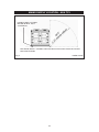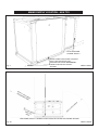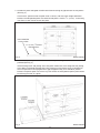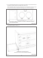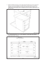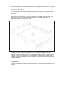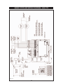
1
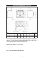
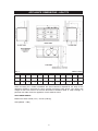
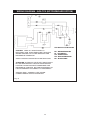
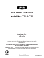
AGA TOTAL CONTROL
Model No. - TC3 & TC5
Installation
Guide
REMEMBER: when replacing a part on this appliance, use only replacement parts
that you can be assured conform to the safety and performance specification that
we require. Do not use reconditioned or copy parts that have not been clearly
authorised by AGA.
PLEASE READ THESE INSTRUCTIONS BEFORE COMMENCING SITE SURVEY
OR INSTALLING THIS APPLIANCE.
IMPORTANT : SAVE INSTRUCTIONS FOR THE LOCAL INSPECTORS USE
CUSTOMER: KEEP THESE INSTRUCTIONS FOR FUTURE REFERENCE
3139291
For use in USA/Canada
09/13 EINS 516294
CONTENTS
SECTION
PAGE
GENERAL NOTES
3
DELIVERY REQUIREMENTS
3
GENERAL INSTALLATION REQUIREMENTS
3
APPLIANCE DIMENSIONS - AGA TC3
4
APPLIANCE DIMENSIONS - AGA TC5
5
INSTALLATION
6
CONNECTING TO THE POWER SUPPLY - AGA TC3
8
POWER SUPPLY - HOTCUPBOARD (AGA TC5)
9
MAINS SUPPLY LOCATION - AGA TC3
10
MAINS SUPPLY LOCATION - AGA TC5
11
HOTCUPBOARD INSTALLATION
12
HANDRAIL CONNECTION - AGA TC3
17
MAINS CORD AND WIRING DIAGRAM - AGA TC3
18
WIRING DIAGRAM - AGA TC5 (HOTCUPBOARD)
19
INSTRUCTIONS
20
CAUTION:
THIS UNIT IS HEAVY, PROPER EQUIPMENT AND ADEQUATE
MANPOWER MUST BE USED IN MOVING THE RANGE TO
AVOID DAMAGE TO THE UNIT OR THE FLOOR
2
GENERAL NOTES
NOTE: THESE INSTALLATION INSTRUCTIONS SHOULD BE LEFT WITH THE APPLIANCE
AND THE USER TO RETAIN FOR FUTURE REFERENCE.
Before installation of an AGA can be made, the site is inspected for suitability by an authorized
AGA distributor and corrected where necessary to conform with local or regional electrical codes.
USA
Model Number AGA TC3
FCC ID: A2M-AGA-TC3
FCC ID: A2M-AGA-TC3CKR
CANADA
Model Number AGA TC3
IC: 10181A-AGATC3CKR
This device complies with part 15 of the
FCC Rules. Operation is subject to
the following two conditions:
(1) This device may not cause harmful
interference, and (2) this device must
accept any interference received,
including interference that may cause
undesired operation.
Model Number AE4M280526
IC: 10181A-AGATC3
DELIVERY REQUIREMENTS
The AGA TC3 arrives on 1 pallet.
The AGA TC5 (Hotcupboard Option) arrives on 2 pallets.
There must be access to the kitchen to manipulate a foot print of 39 9/16” (1005mm) x 29 1/8”
(740mm). A wooden template (skate with castor wheels) of dimensions 39 9/16” (1005mm) x
29 1/8” 740mm could be used to check if the AGA Total Control fully built appliance is able to fit
through the property grounds and doors into its installation position in the kitchen. It must also
be considered that the height of the appliance is 37 6/8” (960mm) off pallet and 43 2/8”
(1100mm) on the pallet, so high level obstacles/restrictions must not be overlooked.
If this skate/template can be manipulated through the property grounds and doors
into position, then the AGA Total Control can be installed as intended with no re-work.
GENERAL INSTALLATION REQUIREMENTS
The installation of the range must be in accordance with the relevant requirements of the local
Wiring and Building Regulations. It should be in accordance also with any relevant requirements
of the Local Authority.
In your own interest and that of safety to comply with the law, all appliances should be installed
by an authorized AGA distributor in accordance with the relevant regulations.
3
APPLIANCE DIMENSIONS - AGA TC3
RH SIDE VIEW
FRONT VIEW
LH SIDE VIEW
PLAN VIEW
MINIMUM WALL POSITION
MINIMUM WALL POSITION
Fig. 1
DESN 516297
A
B
C
D
E
F
G
H
J
K
mm
987
945
910
680
1385
760
1145
698
116
10
ins
38 7/8
37 3/16
35 13/16
26 3/4
54 1/2
29 15/16
45 1/16
27 1/2
4 9/16
3/8
Cooker Dimensions
When surveying for a cooker installation the actual clearance required for the ‘body’ of the
appliance should be increased by 3/8” (10mm) beyond the figures quoted above. This allows
safe margin to take into account the natural dimensional variations found in major castings. In
particular the width across the appliance recess could be critical.
APPLIANCE WEIGHT
Model: AGA Total Control (TC3) - 816 lbs (370 Kg)
PACKAGING WEIGHT
1135 lbs (515 Kg)
DATA PLATE LOCATED BEHIND BOTTOM PLINTH.
4
APPLIANCE DIMENSIONS - AGA TC5
Fig. 2
mm
ins
DESN 516561
A
B
C
D
E
F
G
H
J
K
L
1478
945
910
680
1385
760
1145
698
116
10
634
26 3/4
54 1/2
29 15/16 45 1/16
27 1/2
4 9/16
3/8
24 31/32
58 13/16 37 3/16 35 13/16
Cooker Dimensions
When surveying for a cooker installation the actual clearance required for the ‘body’ of the
appliance should be increased by 10mm beyond the figures quote above. This allows safe
margin to take into account the natural dimensional variations found in major castings. In
particular the width across the appliance recess could be critical.
APPLIANCE WEIGHT
Model: AGA Total Control (TC3) - 816 lbs (370 Kg)
Hotcupboard - 110kg
5
INSTALLATION
Range Base or Hearth
It is essential that the base or hearth on which the range stands should be level and be capable
of supporting the total weight of the range. The base of the built-in AGA plinth must be level and
sit above finished floor height for service access.
Plinth
The front plinth cover is removable and must not be obstructed by flooring or tiles. If necessary
the cooker must be raised by the thickness of the tiles to ensure the plinth can be removed.
Minimum Clearance to Combustibles
A gap of at least 1/2” must be observed between the rear of the top plate, and the wall behind the
appliance. If the rear wall is of combustible material there must be a gap of 1” (25mm).
Side Clearances
A 1/8” (3mm) gap is required each side between the cooker top plate and adjoining work surfaces
that may be fitted, this is to allow for the safe removal of the top plate should this be required at
a later date.
Where cookers are fitted against side walls a 4 9/16” (116mm) side clearance is required on the
right and left hand side for oven doors access.
If the AGA is to be installed in a brick recess, then the minimum clearance should be increased
by at least 3/8” (10mm), to allow for the walls not being square.
In addition a minimum clearance of 39 1/2” (1000mm) must be available at the front of the cooker
to enable the cooker to be serviced.
Tiling
When the cooker is to stand in a recess or against a wall which is to be tiled, under no
circumstances should the tiles overlap the cooker top plate, access to remove the hotplate must
be allowed for servicing at a later date.
Overhead Cabinets
To eliminate the risk of burns or fires by reaching over hot surface units, cabinet storage space
located above the surface units should be avoided.
Range Hoods
It is recommended that this AGA is fitted with a range hood. The AGA venting system is located
on top of the AGA between the two hotplates, and is designed for venting the moisture from the
ovens. The cooker hood should be positioned not less than the minimum height as
recommended by the manufacturer, from the top of the AGA.
6
Fig. 3
DESN 516589
7
CABINETS MUST NOT EXCEED 13”
PROJECTED DEPTH ABOVE THE
RANGE.
DIM ‘D’ TO BE NOT LESS THAN THE
NORMAL WIDTH OF THE
APPLIANCE.
NOTE: ANY OVERHEAD FITTED
CONNECTION TO THE POWER SUPPLY - AGA TC3
Electric Shock Hazard
Rating Plate is located behind removable plinth, see Fig. 4.
Electrical Grounding is required on this appliance.
DO NOT connect to the electrical supply until the appliance is permanently grounded.
Disconnect the power to the junction box before making the electrical connection.
This appliance must be connected to a grounded metallic permanent supply or a
grounding connector should be connected to the grounding terminal or wire lead on the
appliance.
Failure to follow these instructions could result in death or serious injury.
This range must be supplied with a 240V, 60Hz power supply and connected to an individual,
properly grounded branch circuit protected by a circuit breaker or time delay fuse. At 240V, it has
a maximum load of 36 amps. Electric hook-up must be done by a licensed electrician. This unit
must be installed according to local code, or in the absence of local codes, the National Electrical
Code for the country of installation.
Wire sizes (COPPER WIRE ONLY) and connections must conform with the rating of the range
(36-amperes).
l
Product installation requires a separate (not shared) 240v/40 amp circuit protected by an
appropriate branch circuit supply.
l
A time-delay fuse or circuit breaker is required.
l
The service cord provided on your product is fitted with a standard four (4) conductor type
14-50P plug, (matching receptacle 14-50R).
l
The wiring diagram is located on Page 18.
The method of connection to the mains electricity supply must facilitate complete electrical
isolation of the appliance.
The mains connection and isolation should not be positioned above the range and must be
positioned within the area defined in Fig. 4, Page 10.
THIS APPLIANCE MUST BE COMPLETELY ISOLATED FROM THE ELECTRICITY SUPPLY
BEFORE SERVICING. THE APPLIANCE IS DESIGNED FOR THE VOLTAGE STATED ON
THE RATING PLATE, WHICH IS SITUATED BEHIND THE PLINTH COVER.
8
POWER SUPPLY - HOTCUPBOARD (AGA TC5)
The hotcupboard attachment requires an independent single phase supply. It has a
maximum load of 6 amps, protected by an appropriate branch circuit supply.
110/120V 60 Hz FLEXIBLE CORD AND PLUG PARALLEL TYPE. The appliance when installed,
must be electrically grounded in accordance with local or regional codes.
An electrical socket must be provided within 5 feet of the LH side of the appliance and easily
accessible to the user to disconnect. Do not position socket above the appliance.
Take special care when cutting holes in wall or floor. Electrical wires may be behind the wall or
floor covering and could cause an electrical shock if you touch them.
Locate any electrical circuits that could be affected by the installation of this product and
disconnect power circuit.
WARNING
Electrical Grounding Instructions
This appliance is equipped with a (three prong) grounding plug for your protection against a
shock hazard and should be plugged directly into a proper receptacle. Do not cut or remove
the grounding prong from this plug.
Do not have a fuse in the neutral or grounding circuit. A fuse in the neutral or grounding circuit
could result in electrical shock.
Do not use an extension lead with this appliance.
Check with a qualified electrician if you are not sure the appliance is properly grounded.
Failure to follow these instructions could result in death or serious injury.
9
MAINS SUPPLY LOCATION - AGA TC3
RATING LABEL LOCATED
BEHIND PLINTH, PULL
TO REMOVE
THE MAINS SUPPLY CONNECTION AND ISOLATION POINT MUST BE WITHIN
THE ZONE SHOWN
Fig. 4
DESN 516295
10
MAINS SUPPLY LOCATION - AGA TC5
HOTCUPBOARD
POWER SUPPLY
MAINS CABLE FED FROM CONTROL
TRAY LEFT OR RIGHT EXIT
THROUGH DUCTING DEPENDENT
UPON POSITION OF SUPPLY
SOCKET
Fig. 5
DESN 516562
RATING LABEL LOCATED BEHIND PLINTH, PULL TO REMOVE,
THE MAINS SUPPLY CONNECT POINT MUST BE WITHIN THE ZONES SHOWN
Fig. 5A
DESN 516590
11
HOTCUPBOARD INSTALLATION
NOTE: The AGA TC5 hotcupboard should arrive with the top plate in a jacked up position. This
is to allow the complete appliance to be slid onto its plinth when alongside the AGA TC3 without
the top plate clashing. The hotcupboard top plate should then be wound down to its correct
height once the appliance is in its final position.
1. Detach hotcupboard from the plinth by removing two screws and tongue bracket from plinth
(See Fig. 6). Slide hotcupboard forwards and away from rear fixing bracket (See Fig. 7).
Fig. 6
DESN 516448
Fig. 7
DESN 516449
12
2. Position the plinth alongside the AGA Total Control leaving no gap between the two plinths
(See Fig. 8).
Check with a spirit level that the plinth level is correct, and also check height differential
between the hotcupboard plinth and Total Control plinth is correct 7/16” (11mm). If necessary,
use shims in each corner to level the plinth.
HOTCUPBOARD
PLINTH BASE
7/16”
+1
(11mm) - 0 HEIGHT
DIFFERENTIAL
Fig. 8
DESN 516564
3. Attach hotcupboard plinth to the AGA Total Control plinth using M6 screws and washers
provided (See Fig. 9).
Attach locking screw and jacking screw into plinth. Make sure at this stage that the jacking
screw does not protrude beyond outer face of plinth. Ensure locking screw is located into
AGA TC3 plinth but not fully tightened. A gap of approximately 3mm should be present
between the plinths apart from at the very front where the hotcupboard spacer plate should
be touching the AGA TC3 plinth,
Fig. 9
DESN 516550
13
4. Run a straight edge along the front of the AGA Total Control plinth, to ensure the front face of
both plinths sit squarely against the straight edge. (See Fig. 10)
When satisfied both plinths sit squarely, jacking screws can be tightened until they just make
contact with the AGA Total Control plinth and locking screws can now be tightened.
USE STRAIGHT EDGE ACROSS BOTH PLINTHS TO ENSURE PLINTHS
ARE ALIGNED SQUARELY
Fig. 10
DESN 516551
5. Front jointing bracket can now be hooked into place over the two pot magnets. This will latch
the two plinths together. (See Fig. 11)
HOOK FRONT JOINTING BRACKET
INTO PLACE TO LOCK TWO PLINTHS TOGETHER
Fig. 11
DESN 516567
14
6. Slide hotcupboard onto plinth until rear tongue bracket engages fully into rear of base slot,
(See Fig. 12). Ensure the appliance is aligned squarely with the plinth then proceed to
engage the front tongue bracket into the slot on the underside of the base plate. Once
satisfied that the front tongue bracket is engaged fully lock it into place by tightening the two
M6 screws fully.
Fig. 12
DESN 516552
7. The hotcupboard top plate is set 13/64 (5mm) higher than the AGA Total Control top plate. This
is to prevent damage to the enamel during installation. Lower the top plate using the
adjusters (See Figs. 13 and 14).
Fig. 13
DESN 516591
15
8. Using the stay rod nut adjusting tool, carefully lower the top plate adjusting nuts until the top
plate sits at the required height, making sure that the top sits level and matches the height of
the AGA TC3. (See Fig. 14).
For servicing requirement, top plate should be removed by raising adjusters approximately
5mm, the top plate can now be removed easily without causing damage to the enamelled
surfaces.
When removing the top plate, the switch wiring harness should be disconnected from the
main wiring harness at the connection point located at the front left hand side of the
appliance, beneath the formex cover sheet.
Fig. 14
DESN 516555
9. Slide the complete handrail assembly over the left hand and centre fixing studs. Once the
assembly has been fitted to the AGA appliance, fit the handrail endcaps (ensuring the
handrail is evenly spaced at each end). The endcaps should be carefully pushed into place
until they sit flush with the outside face of each bracket. (A light smear of lubricant, such as
washing up liquid can be applied to the end cap rubber ‘O’ rings to aid fitment of endcaps into
handrail if required).
The handrail can now be locked into place using the grub screws on the underside of the
handrail brackets.
Finally fit plinth facia onto magnets positioned on plinth, ensuring the facia sits squarely and
centrally.
.
16
Fig. 15
DESN 516569
HANDRAIL CONNECTION - AGA TC3
Fig. 16
DESN 516560
Handrail brackets. endcaps and handrails require assembly.
Locate endcaps onto handrail, place brackets over endcaps and then slide complete assembly
onto locating studs.
Once assembly is correctly located, lock into position with grub screws (located on underside
of handrail).
17
MAINS CORD AND WIRING DIAGRAM - AGA TC3
Fig. 17
18
WIRING DIAGRAM - AGA TC5 (HOTCUPBOARD OPTION)
COLOUR KEYS/COLLEURS
CAUTION: LABEL ALL WIRES PRIOR TO
DISCONNECTION, WHEN SERVICING CONTROLS
WIRING ERRORS CAN CAUSE IMPROPER AND
DANGEROUS OPERATION.
VERIFY PROPER OPERATION AFTER SERVICING
ATTENTION: ETIQUETEZ TOUS LES CABLES AVANT
DE LES DEBRANCHER LORS DE LES BRANCHER
LORS DE L’ENTRETIEN DES COMMANDES. DES
ERREURS DE CABLAGE PEUVENT ENTRAINER UN
FONCTIONNEMENT INCORRECT ET DANGEREUX.
VERIFIEZ QUE L’ APPAREIL FONCTIONNE
CORRECTEMENT APRES L’ENTRETIEN.
Fig. 18
19
BR - BROWN/MARRON
BL - BLUE/BLEU
GR - GREEN/VERT
OR - ORANGE/ORANGE
BK - BLACK/NOIR
INSTRUCTIONS
Attach warning hanger (EGLL516660) located in literature pack, to AGA Total Control handrail
when installation is complete. Advise customer to remove and read warning label.
Hand this Installation Guide to the user for retention and instruct in the safe operation of the
appliance.
Also advise the user that, for continued efficient and safe operation of the appliance, servicing is
carried out at intervals recommended by the AGA distributor.
20
21
22
23
For further advice or information contact
your local AGA Specialist
With AGA’s policy of continuous product
improvement, the Company reserves the right to
change specifications and make modifications to
the appliance described and illustrated at any time
US Office:
AGA MARVEL
1260 E Van Deinse St.
Greenville, MI 48838
www.agamarvel.com
24