1
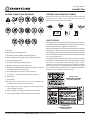
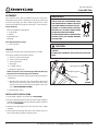
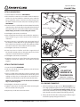
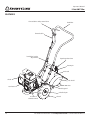
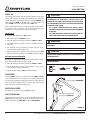
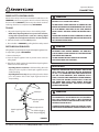
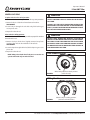
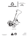
Operator's Manual Original Operating Instructions 17306 CRT Tiller GAS/OIL RATIO Product #: 17306 Email for more information [email protected] 50:1 P/N: 17459 ECN: 10117 REV1: 09/04/13 © 2014 Ardisam, Inc. All Rights Reserved Operator’s Manual 17306 CRT Tiller INTRODUCTION Thank you for purchasing the 17306 CRT Tiller from CountyLine®. We have worked to ensure that this tiller meets the highest standards for usability and durability. With proper care, your tiller will provide many years of service. Please read this entire manual before installation and use. CountyLine reserves the right to change, alter or improve the product and this document at any time without prior notice. CONTENTS Registration..........................................................................................................................................................................................................................................2 Warnings and Safety Precautions.............................................................................................................................................................................................3-7 Assembly...........................................................................................................................................................................................................................................8-9 Features.............................................................................................................................................................................................................................................. 10 Operation.....................................................................................................................................................................................................................................11-15 Maintenance...............................................................................................................................................................................................................................16-19 Storage................................................................................................................................................................................................................................................ 19 Troubleshooting.............................................................................................................................................................................................................................. 20 Warranty............................................................................................................................................................................................................................................. 21 Parts................................................................................................................................................................................................................................................22-27 Dipstick Cut-Outs............................................................................................................................................................................................................................ 27 REGISTRATION AND SERVICE Record the product model number and serial number in the space provided for easy reference when ordering parts or requesting technical support. Excluding emissions-related warranty items, the warranty is valid only if the completed registration is received by Ardisam within 30 days of purchase. (SEE WARRANTY SECTION FOR MORE INFORMATION) You can register your warranty by mailing it to: Ardisam Inc, 1160 Eighth Avenue, Cumberland, WI 54829. You may also call our customer service department at (800) 345-6007 Mondays through Fridays from 8 a.m. to 5 p.m. CST. Serial Number Location V 14 60 . O N L O. m E D L N co e. O M RIA ak E thqu S SN 4V 01 L6 LB ar te ge OWNERSHIP RECORDS Owner’s Name: Owner’s Address: City: State/Province: Model Number: Date of Purchase: Notes: Serial Number: Zip Code/Postal Code: Read and keep this manual for future reference. This manual contains important information on SAFETY, ASSEMBLY, OPERATION, AND MAINTENANCE. The owner must be certain that all the product information is included with the unit. This information includes the MANUAL, the REPLACEMENT PARTS and the WARRANTIES. This information must be included to make sure state laws and other laws are followed. All persons to whom rent/loan this unit must have access to and understand this information. This manual should remain with the product even if it is resold. 2 For additional information email [email protected] or call 800-345-6007 M-F 8-5 Operator’s Manual 17306 CRT Tiller WARNINGS AND SAFETY PRECAUTIONS OWNER’S RESPONSIBILITY Accurate assembly, and safe and effective use of the rototiller is the owner’s responsibility. • Read and follow all safety instructions. • Carefully follow all assembly instructions. • Maintain the tiller according to directions and schedule included in this CountyLine operator’s manual. • Ensure that anyone who uses the tiller is familiar with all controls and safety precautions. SPECIAL MESSAGES Your manual contains special messages to bring attention to potential safety concerns, machine damage as well as helpful operating and servicing information. Please read all the information carefully to avoid injury and machine damage. NOTE: General information is given throughout the manual that may help the operator in the operation or service of the machine. IMPORTANT SAFETY PRECAUTIONS Please read this section carefully. Operate the tiller according to the safety instructions and recommendations outlined here and inserted throughout the text. Anyone who uses this tiller must read the instructions and be familiar with the controls. Your tiller is equipped with a safety device that enables you to stop the wheels and tines quickly in an emergency. Learn how the drive safety control lever operates and how to control the tiller at all times. This symbol points out important safety instructions which if not followed could endanger your personal safety. Read and follow all instructions in this manual before attempting to operate this equipment. • Do not allow children to operate this rototiller. Keep small children away from the area being tilled. Do not allow adults to operate the tiller without proper instruction. Intended Use / Foreseeable Misuse IMPORTANT: This is a motorized rotary tiller that works the soil by means of rotating tines. It is pedestrian-controlled and selfpropelled, with a gasoline-fueled internal combustion engine to power the wheels and tines. It shall not be used for any other purpose. SRT DANGER DANGER INDICATES A SERIOUS INJURY OR FATALITY WILL RESULT IF THE SAFETY INSTRUCTIONS THAT FOLLOW THIS SIGNAL WORD ARE NOT OBEYED. WARNING WARNING INDICATES A SERIOUS INJURY OR FATALITY COULD RESULT IF THE SAFETY INSTRUCTIONS THAT FOLLOW THIS SIGNAL WORD ARE NOT OBEYED. CAUTION CAUTION INDICATES YOU CAN OR YOUR EQUIPMENT CAN BE HURT IF THE SAFETY INSTRUCTIONS THAT FOLLOW THIS SIGNAL WORD ARE NOT OBEYED. IMPORTANT IMPORTANT INDICATES HELPFUL INFORMATION FOR PROPER ASSEMBLY, OPERATION, OR MAINTENANCE OF YOUR EQUIPMENT. WARNING YOU MUST READ, UNDERSTAND AND COMPLY WITH ALL SAFETY AND OPERATING INSTRUCTIONS IN THIS MANUAL BEFORE ATTEMPTING TO SETUP AND OPERATE YOUR ROTOTILLER. FAILURE TO COMPLY WITH ALL SAFETY AND OPERATING INSTRUCTIONS CAN RESULT IN LOSS OF MACHINE CONTROL, SERIOUS PERSONAL INJURY TO YOU AND/OR BYSTANDERS, AND RISK OF EQUIPMENT AND PROPERTY DAMAGE. THE TRIANGLE IN THE TEXT SIGNIFIES IMPORTANT CAUTIONS OR WARNINGS WHICH MUST BE FOLLOWED. CALIFORNIA PROPOSITION 65 WARNING ENGINE EXHAUST FROM THIS PRODUCT CONTAINS CHEMICALS KNOWN TO THE STATE OF CALIFORNIA TO CAUSE CANCER, BIRTH DEFECTS, OR OTHER REPRODUCTIVE HARM. DANGER CRT For additional information email [email protected] or call 800-345-6007 M-F 8-5 3 Operator’s Manual 17306 CRT Tiller GENERAL SAFETY RULES • • • • • • • • • • • • • • • 4 Read, understand, and follow all instructions on the machine and in the manual(s). Be thoroughly familiar with the controls and the proper use of the machine before starting. Use this equipment for its intended purpose only. Familiarize yourself with all of the safety and operating decals on this equipment and on any of its attachments or accessories. Do not put hands or feet near or under rotating parts. Only allow responsible individuals who are familiar with the instructions to operate the machine. Do not allow children to operate this machine. Do not allow adults to operate the machine without proper instruction. Thoroughly inspect the area where the machine is to be used and remove all foreign objects. Your equipment can propel small objects at high speed causing personal injury or property damage. Stay away from breakable objects, such as house windows, automobiles, greenhouses, etc. Wear appropriate clothing such as a long-sleeved shirt or jacket. Also wear long trousers or slacks. Do not wear shorts. Never wear sandals, sneakers or open shoes, and never operate the machine with bare feet. Do not wear loose clothing or jewelry. They can get caught in moving parts. Always keep hands, feet, hair and loose clothing away from any moving parts on engine and machine. Always wear safety goggles or safety glasses with side shields when operating the machine to protect your eyes from foreign objects which can be thrown from the unit. Always wear a protective hearing device. Always wear work gloves and sturdy footwear. Wear footwear that will improve footing on slippery surfaces. Leather work shoes or short boots work well for most people. These will protect the operator’s ankles and shins from small sticks, splinters, and other debris. It is advisable to wear protective headgear to prevent the possibility of being struck by small flying particles, or being struck by low hanging branches, twigs, or other objects which may be unnoticed by the operator. Do not operate the machine without proper guards or other safety protective devices in place. See manufacturer’s instructions for proper operation and installation of accessories. Only use accessories approved by the manufacturer. Operate only in daylight or good artificial light. Do not operate product when fatigued or under the influence of alcohol, drugs or other medication which can cause drowsiness or affect your ability to operate this machine safely. • • • • • • • • • • • Never operate machine in wet grass. Always be sure of your footing; keep a firm hold on the handle and walk; never run. Watch for traffic when operating near, or when crossing roads. If the equipment should start to vibrate abnormally, stop the engine (motor), flip the ON/OFF switch to the OFF position. Check immediately for cause. Vibration is generally a warning of trouble. If the noise or vibrations of the machine increase, stop immediately and perform an inspection. Never leave the machine unattended when the engine is running. Flip the ON/OFF switch to the OFF position. Regularly inspect the machine. Make sure parts are not bent, damaged or loose. Temperature of muffler and nearby areas may exceed 150° F (65° C). Allow muffler and engine areas to cool before touching. Never pick up or carry the machine while the engine is running. Prolonged exposure to noise and vibration from gasoline enginepowered equipment should be avoided. Take intermittent breaks and/or wear ear protection from engine noise as well as heavy work gloves to reduce vibration in the hands. Keep all screws, nuts and bolts tight. Do not transport the machine from one place to another with the engine running. When moving the packaged machine, always do so with a partner. Check local regulations for age restrictions on use of this machine. PRODUCT-SPECIFIC SAFETY RULES • • • • Do not till above underground utilities, including water lines, gas lines, electric cables, or pipes. Do not operate the machine on terrain/soil with large rocks and foreign objects which can damage the equipment. After striking a foreign object, stop the engine. Flip the ON/ OFF switch to the OFF position. Inspect the machine for damage. If damaged, repair before starting and operating the machine. The tines of the tiller should not rotate when the drive control lever is released into the neutral position. If it does rotate when in neutral, contact CountyLine customer service for instruction. If an object becomes lodged in the tines, flip the ON/OFF switch to the OFF position, allow to cool before attempting to remove the foreign object. For additional information email [email protected] or call 800-345-6007 M-F 8-5 Operator’s Manual 17306 CRT Tiller ENGINE SAFETY PRECAUTIONS WARNING Warning Carbon Monoxide Poisoning ENGINES GIVE OFF CARBON MONOXIDE, AN ODORLESS, COLORLESS, POISONOUS GAS. CARBON MONOXIDE MAY BE PRESENT EVEN IF YOU DO NOT SMELL OR SEE ANY ENGINE EXHAUST. BREATHING CARBON MONOXIDE CAN CAUSE NAUSEA, FAINTING OR DEATH, IN ADDITION TO DROWSINESS, DIZZINESS AND CONFUSION. Engines give off carbon monoxide, an odorless, colorless, poisonous gas. Carbon monoxide may be present even if you do not smell or see any engine exhaust. Breathing carbon monoxide can cause nausea, fainting or death, in addition to drowsiness, dizziness and confusion. If you experience any of these symptoms, seek fresh air and medical attention immediately. If your product comes with a separate engine manual, be sure to read and follow all safety and warning precautions outlined there, in addition to any in this manual. IF YOU EXPERIENCE ANY OF THESE SYMPTOMS, SEEK FRESH AIR AND MEDICAL ATTENTION IMMEDIATELY. Preventing Carbon Monoxide Poisoning • Always start and run engine outdoors. Do not start or run engine in an enclosed area, even if doors or windows are open. CAUTION HOT GASES ARE A NORMAL BY-PRODUCT OF A FUNCTIONING INTERNAL COMBUSTION ENGINE. FOLLOW ALL SAFETY INSTRUCTIONS TO PREVENT BURNS AND FIRES. • Never try to ventilate engine exhaust indoors. Carbon monoxide can reach dangerous levels very quickly. • Never run engine outdoors where exhaust fumes may be pulled into a building. DO NOT ALTER/MODIFY ENGINE: • Never run engine outdoors in a poorly ventilated area where the exhaust fumes may be trapped and not easily taken away. (Examples include: in a large hole or areas where hills surround your working area.) NEVER ALTER OR MODIFY THE ENGINE FROM THE FACTORY. SERIOUS INJURY OR DEATH MAY OCCUR IF ENGINE IS MODIFIED OR ALTERED. WHEN WORKING ON OR REPLACING PARTS FOR THE ENGINE OR PRODUCT, YOU MUST ALWAYS FLIP THE ON/OFF SWITCH TO THE OFF POSITION. • Never run engine in an enclosed or partially enclosed area. (Examples include: buildings that are enclosed on one or more sides, under tents, car ports or basements.) • Always run the engine with the exhaust and muffler pointed in the direction away from the operator. • Never point the exhaust muffler towards anyone. People should always be many feet away from the operation of the engine and its attachments. • Do not change the engine governor settings or over-speed the engine. Gasoline Fires and Handling Fuel Safely • • • Use extra care in handling gasoline and other fuels. They are flammable and vapors are explosive. • • • When storing extra fuel be sure that it is in an appropriate container and away from any fire hazards. Prevent fire and explosion caused by static electric discharge. Use only nonmetal, portable fuel containers approved by the Underwriter’s Laboratory (U.L.) or the American Society for Testing & Materials (ASTM). Always fill fuel tank outside in a well ventilated area. Never fill your fuel tank with fuel indoors. (Examples include: basement, garage, barn, shed, house, porch, etc.) Never fill tank near appliances with pilot lights, heaters, or other ignition sources. If the fuel has to be drained, this should • • • • • be done outdoors. The drained fuel should be stored in a container specifically designed for fuel storage or it should be disposed of carefully. Never remove the fuel cap or add fuel with the engine running. Stop engine and allow to cool before filling. Never drain fuel from engine in an enclosed area. Always wipe up excess (spilled) fuel from engine before starting. Clean up spilled fuel immediately. If fuel is spilled, do not start the engine but move product and fuel container from area. Clean up spilled fuel and allow to evaporate and dry after wiping and before starting. Allow fuel fumes/vapors to escape from the area before starting engine. Test the fuel cap for proper installation before starting and using engine. Always run the engine with fuel cap properly installed on the engine. Never smoke while refilling engine fuel tank. Do not store engine with fuel in fuel tank indoors. Fuel and fuel vapors are highly explosive. For additional information email [email protected] or call 800-345-6007 M-F 8-5 5 Operator’s Manual 17306 CRT Tiller OPERATION SAFETY RULES • Never operate the tiller without guards, covers and hoods in place. • Never start the engine or operate the tiller with the wheels in the free-wheel position. Make sure the wheel lock pins are engaged through the wheel hubs and wheel axle. The wheels act as a brake to keep the tiller at a controlled speed. Disengage wheel lock pins to permit free-wheeling only when engine is stopped. • Keep hands, feet and clothing away from rotating parts. Keep clear of tiller tines at all times. • Tines and wheels rotate when the drive safety control lever is pulled toward the handle bar (FORWARD position). Releasing the drive safety control lever to the NEUTRAL position stops the wheels and tines. If the unit does not stop when the lever is in the NEUTRAL position an adjustment of the drive control linkage, the belt alignment or the belt guides is required. • Use extreme caution when operating on or crossing gravel drives, walks or roads. Stay alert for hidden hazards or traffic. • After striking a foreign object, stop the engine, remove the wire from the spark plug, thoroughly inspect the tiller for any damage and repair the damage before restarting and operating the tiller. • If vegetation clogs the tines STOP THE ENGINE AND DISCONNECT THE SPARK PLUG WIRE before removing vegetation by hand. IMPORTANT THE RIGHT AND LEFT SIDES OF YOUR ROTOTILLER ARE DETERMINED FROM THE OPERATING POSITION AS YOU FACE THE DIRECTION OF FORWARD TRAVEL. L R ENGINE IS SHIPPED FROM FACTORY WITHOUT OIL. YOU MUST ADD ENGINE OIL BEFORE STARTING ENGINE. IMPORTANT NEVER START THE ENGINE OR OPERATE THE TILLER WITH THE WHEELS IN THE FREE-WHEEL POSITION. MAKE SURE THE WHEEL LOCK PINS ARE ENGAGED THROUGH THE WHEEL HUBS AND WHEEL AXLE. THE WHEELS ACT AS A BRAKE TO KEEP THE TILLER AT A CONTROLLED SPEED. DISENGAGE WHEEL LOCK PINS TO PERMIT FREE-WHEELING ONLY WHEN ENGINE IS STOPPED. MAINTENANCE AND STORAGE • Keep machine, attachments and accessories in safe working condition. • Engine muffler will be hot from operation. Do not touch it with bare skin or a severe burn may result. • Check shear bolts, engine mounting bolts and other bolts at frequent intervals for proper tightness to be sure the equipment is in safe working condition. • If the unit should start to vibrate abnormally, stop the engine and check immediately for the cause. Vibration is generally a warning of trouble. • To prevent accidental starting, always disconnect and secure the spark plug wire from the spark plug before performing tiller maintenance. • Do not run the engine indoors; exhaust fumes are deadly. • Never run the engine indoors. Exhaust fumes are deadly. • Do not overload the machine capacity by attempting to till too deep at too fast a rate. • Always allow muffler to cool before filling fuel tank. • Never allow bystanders near the unit. • Use only attachments and accessories approved by the manufacturer of the tiller. • Never operate the tiller without good visibility or light. • Be careful when tilling in hard ground. The tines may catch in the ground and propel the tiller backward. If this occurs, let go of the handle bars and do not restrain the machine. • Take all possible precautions when leaving the machine unattended. Disengage all control levers, stop the engine, wait for all moving parts to stop and make certain guards and shields are in place. • Never store equipment with gasoline in the tank inside of a closed building where fumes may reach an open flame or spark. Allow the engine to cool before storing in any building. • Always refer to the operator’s guide instructions for important details if the tiller is to be stored for an extended period. • Add a fuel stabilizer to gas tank and run for 10-15 minutes to prevent fuel from gumming up during an extended storage period. • Storing outdoor power equipment inside or using a cover to protect against water and sunlight has been proven to minimize maintenance costs and prolong the life of the machine. • When leaving the operating position for any reason: - shut off the engine. - wait for all moving parts to stop. 6 For additional information email [email protected] or call 800-345-6007 M-F 8-5 Operator’s Manual 17306 CRT Tiller HAZARD SYMBOLS AND MEANINGS CONTROL AND OPERATING SYMBOLS Pictured below are control and operating symbols on the unit or in this manual. Before you operate your unit, learn and understand the purpose for each symbol. A B C D E F G H I J K L On/Off Choke Fuel Shutoff SAFETY DECALS M N O P A: Warning! B: Avoid Injury From Rotating Tines. C: Read Owner’s Manual Before Operating Machine. D: Remove Objects that Could Be Thrown By This Machine. E: Dangerous Moving Parts. F: Be Aware of Moving and Rotating Parts. G: Wear Ear and Eye Protection At All Times. H: Do Not Service or Adjust Moving Parts Unless Engine is Stopped and Spark Plug Wire is Disconnected. This rototiller unit has been designed and manufactured to provide you with the safety and reliability you would expect from an industry leader in outdoor power equipment manufacturing. Although reading this manual and the safety instructions it contains will provide you with the necessary basic knowledge to operated this equipment safely and effectively, we have placed several safety labels on the tiller to remind you of this important information while you are operating the unit. These safety labels are illustrated below, and are shown here to help familiarize you with the location and content of the safety messages you will see as you perform normal tilling operations. Please, review these decals now, and if you have any questions regarding their meaning or how to comply with these instructions, reread the complete safety instruction text in this manual. For additional questions contact CountyLine customer service. I: Dress Appropriately And Wear Sturdy Footwear. J: Toxic Fumes—Do Not Operate in Unventilated Areas. K: Hot Surfaces. L: Fire Hazards. Part No. 17052 MOVING PARTS WARNING Frame Near Belt Decal M.Do Not Use In Thunderstorms--For severe weather, stop operation of this machine and seek shelter. N. Team Lift--For your safety, always have at least two people when lifting this machine. O. Do Not Till Above Underground Utility Lines And Pipes. P. Do Not Operate When Children Or Others Are Around. Part No. 17051 DANGER & WARNINGS Hood Flap Decal For additional information email [email protected] or call 800-345-6007 M-F 8-5 7 Operator’s Manual 17306 CRT Tiller ASSEMBLY Your rototiller comes fully assembled except for a few parts. The following instructions will help you unpack your tiller and assemble and adjust your tiller’s depth regulator lever, cable tension and handle bar height. You will need 2- 9/16” wrenches. Carton Contents IMPORTANT THE RIGHT AND LEFT SIDES OF YOUR ROTOTILLER ARE DETERMINED FROM THE OPERATING POSITION AS YOU FACE THE DIRECTION OF FORWARD TRAVEL. L R ENGINE IS SHIPPED FROM FACTORY WITHOUT OIL. YOU MUST ADD ENGINE OIL BEFORE STARTING ENGINE. Rear Tine Rototiller w/Handle Bar 2 - Side Shields 2 - Wheels Depth Regulator Parts Bag TILLER TRANSMISSION IS SHIPPED FROM FACTORY WITH THE PROPER AMOUNT OF GEAR LUBE. Tools Required for Assembly 2 - 9/16” wrenches CAUTION UNPACK 1. Open top of carton and remove handle bar assembly. 2. Find parts packet. Parts packet contains: 4 - 3/8-16 x 1-3/4” hex head bolts 6 - 1/4-20 x 3/4” hex head bolts 6 - 1/4-20 nylock nuts 1 - detent pin 12 - 1/4” flat washers 2 - Handle bar extensions DO NOT TRY TO LIFT THE ROTOTILLER FROM THE CARTON. DO NOT ADD ENGINE OIL INTO GEAR CASE DIPSTICK HOLE. adjusting knob NOTE: Parts packet also includes Engine Manual, Warranty Registration Card and this Operator’s Manual. 3. Cut open seems of carton, exposing all contents and remove machine by: a. Attaching loose wheels in box onto machine with wheel lock pins in free-wheel position. Slide wheel all the way onto the axle and insert lock pin through the axle hole only. (SEE OPERATION SECTION) depth regulator detent pin FIGURE 1 b. Roll tiller from carton. INSTALL DEPTH REGULATOR 1. Locate depth regulator and detent pin. SEE FIGURE 1 2. Unscrew adjusting knob from the top of the depth regulator and slide depth regulator up into vertical slot at the rear of the tine shield. SEE FIGURE 1 3. Reattach the adjusting knob to the top hole of the depth regulator. 4. Insert detent pin through the hole in the vertical slot and a hole in the depth regulator to hold it in place. 8 For additional information email [email protected] or call 800-345-6007 M-F 8-5 Operator’s Manual 17306 CRT Tiller ATTACH HANDLE BAR 1.Locate handle bar extensions. SEE FIGURE 2 2.Place handle bar extensions on outside of lower handle bar mount. Line up the handle bar extension pieces with the lower handle bar mount as shown in the decal located on the lower handle bar mount next to the mounting location. SEE FIGURE 2 3.Insert one 3/8-16 x 1 3/4” bolt for each side in lower holes of the extension pieces. The bolts will pass through the lower hole of the lower handle bar mount. Put 3/8” flat washers onto bolts. handle bar extensions handle bar lower handle bar mount NOTE: Always put washers on the tubing side of bolts. 4.Hand tighten 3/8-16 nuts on each bolt. FIGURE 2 5.Now assemble the handle bar to the handle bar extensions. Note: Handle bar goes to the outside of the handle bar extensions. 6.Insert one 3/8-16 x 1-3/4” bolt for each side in lower holes of the handle bar. Note: Bolts will be going through the upper holes of the lower handle bar mount along with the middle holes of the extensions. Put 3/8” flat washers onto bolts. washers & botls 7.Hand tighten 3/8-16 nuts on each bolt. side shield 8.Insert one 3/8-16 x 1 bolt for each side in upper holes of the handle bar. Bolts will pass through upper holes of the extensions. Put 3/8” flat washers onto bolts. FIGURE 3 9.Hand tighten 3/8-16 nuts on each bolt. 10. Tighten 3/8-16 nuts on each of the 6 bolts connecting the handle bar, handle bar extensions and handle bar mount together. IMPORTANT gear case dipstick ATTACH TINE SIDE SHIELDS transmission cover plate 1. Locate side shields. SEE FIGURE 3 2. Take one side shield, raise it up against one side of the tine guard and hold in place. DO NOT PUT ENGINE OIL IN TRANSMISSION 3. Place a 1/4” flat washer onto three 1/4-20 x 3/4” bolts. Insert these three bolts in each of the three holes of the tine guard, making sure they also pass through the side shield. Put an additional 1/4” flat washers onto the underside of the bolts. NOTE: The side shield needs to be below the tine hood when they are attached together. 4. Hand tighten 1/4-20 nuts on each bolt. 5. Tighten 1/4-20 nuts on each of the three bolts connecting the two side shields to the tine guard. 6. Repeat steps 2-4 for the second side shield. LUBRICANT IS ALREADY INSTALLED IN TRANSMISSION. FILL ENGINE CRANKCASE 1. Add oil according to engine manual. Do not overfill. Use a clean, high quality detergent oil. Use no special additives with recommended oils. Do not mix oil with gasoline. Oil level must be full. Check the oil level by removing oil fill plug. Oil level should be up to the bottom of the fill plug opening. 2. Always check oil level before starting engine. Refer to engine manual for capacity and type of oil to use. For additional information email [email protected] or call 800-345-6007 M-F 8-5 9 Operator’s Manual 17306 CRT Tiller FEATURES forward drive safety control lever handlebar forward cable handle bar height adjustment depth regulator lever detent pin tine hood choke side shield tines recoil start belt guard wheel lock pin on/off and throttle control 10 wheels For additional information email [email protected] or call 800-345-6007 M-F 8-5 Operator’s Manual 17306 CRT Tiller OPERATION PREPARATION • Dress appropriately when operating the tiller. Always wear sturdy footwear. Never wear sandals, sneakers or open shoes, and never operate the tiller with bare feet. Do not wear loose clothing that might get caught in moving parts. • Carefully inspect the area to be tilled and remove all foreign objects. Do not till above underground water lines, gas lines, electric cables, or pipes. Do not operate the tiller in soil with large rocks and foreign objects which can damage the equipment. • Disengage all clutches and leave all control levers in the neutral position before starting the engine. • Handle fuel with care; it is highly flammable. a. Use an approved fuel container. b. Never add fuel to a running engine or hot engine. c. Fill fuel tank outdoors with extreme care. Never fill fuel tank indoors. d. Replace gasoline cap securely and clean up spilled fuel before restarting. • Never attempt to make any adjustments while the engine is running. PRE-START INSPECTION 1. Make sure all safety guards are in place and all nuts and bolts are secure. 2. Check oil level in engine crankcase. See your engine manual for procedure and specifications. 3. Inspect air cleaner for cleanliness. See your engine manual for procedure. 4. Check the fuel supply. Fill the fuel tank no closer than 1 inch from top of tank to provide space for expansion. See your engine manual for fuel recommendations. 5. Be sure spark plug wire is attached and spark plug is tightened securely. CAUTION PLEASE DO NOT START YOUR TILLER UNTIL YOU HAVE READ THE MANUAL THAT CAME WITH YOUR ENGINE, AND THE SECTIONS IN THIS MANUAL TITLED CONTROLS, ADJUSTMENTS AND SAFETY. IF YOU HAVE READ THESE, FOLLOW THE STEPS BELOW TO START YOUR TILLER. ALWAYS PERFORM THIS PRE-START CHECKLIST BEFORE STARTING THE ENGINE. WARNING GASOLINE IS HIGHLY FLAMMABLE AND MUST BE HANDLED WITH CARE. NEVER FILL THE TANK WHEN THE ENGINE IS HOT OR RUNNING. ALWAYS MOVE OUTDOORS TO FILL THE TANK. WHEELS MUST ALWAYS BE LOCKED IN THE TILLING POSITION WHEN ENGINE IS RUNNING. DO NOT OPERATE THE TILLER WITH THE WHEEL LOCKOUTS UNLOCKED. ALWAYS SET THE WHEELS IN TILLING POSITION BEFORE STARTING ENGINE. ALWAYS PUT THE DEPTH REGULATOR LEVER IN THE TRANSPORT POSITION BEFORE STARTING ENGINE. TINES SHOULD CLEAR THE GROUND. IMPORTANT ENGINE IS SHIPPED FROM FACTORY WITHOUT OIL. YOU MUST ADD ENGINE OIL BEFORE STARTING ENGINE. ENGINE PREPARATION See the engine manufacturer’s instructions for the type of gasoline and oil to use. Before you use the unit, read the information on safety, operation, maintenance, and storage. NOTE: Engine does not contain OIL or GASOLINE. Fill Crankcase With Oil 6. Check position of wheels and wheel lock pins. Lock pins should be in the tilling position with the pins being through both the axle holes and wheel holes See the engine manual for instructions on the type of oil to use and how to fill engine with oil. 7. Check depth regulator lever position. See the engine manual for instructions on the type of gasoline to use. 8. Examine underneath and around engine for signs of oil or fuel leaks. Fill Fuel Tank With Gasoline 9. Inspect fuel hoses for tightness and fuel seepage. 10.Look for signs of engine damage. 11.Remove excessive debris from muffler area and recoil starter. For additional information email [email protected] or call 800-345-6007 M-F 8-5 11 Operator’s Manual 17306 CRT Tiller START-UP The controls required to start and run the rototiller are located on the engine and are the choke lever, throttle lever and On/Off switch. The choke lever is marked on one end with CHOKE and on the other with RUN. The throttle lever is marked on one end with a SLOW icon and on the other with a FAST icon. A more detailed description of engine operation and all related precautions and procedures can be found in the engine manufacturer’s manual that accompanies each tiller. COLD STARTS CAUTION THIS INFORMATION IS PROVIDED HERE ONLY TO INTRODUCE THE CONTROLS. DO NOT START THE ENGINE AT THIS TIME. PLEASE READ THIS SECTION AND ALL OPERATING AND SAFETY INSTRUCTIONS BEFORE STARTING YOUR TILLER. • AS A SAFETY PRECAUTION, THE DRIVE SAFETY CONTROL LEVER WILL NOT LOCK IN THE FORWARD POSITION. • TO STOP THE WHEELS AND TINES AT ANY TIME RELEASE THE DRIVE SAFETY CONTROL LEVER. 1. Turn ON/OFF switch to the ON position. 2. Move choke lever to CHOKE position. 3. Move throttle lever to half way between SLOW and FAST. 4. Pull starting rope out slowly one time and allow to return normally. 5. Pull starting rope out rapidly, and allow rope to return normally. Repeat until engine starts. 6. When engine starts, gradually move choke lever to RUN position and move throttle lever to FAST position for tilling. RESTARTING A WARM ENGINE Restarting an engine that is already warm from previous running does not normally require use of the choke. 1. Move throttle lever to half way between SLOW and FAST. 2. Pull starting rope out rapidly, and allow rope to return normally. Repeat until engine starts. 3. Adjust throttle speed to FAST position for tilling. WARNING ENGINE SHOULD BE OFF BEFORE ADJUSTING ANY CONTROLS. DANGER ALWAYS KEEP HANDS AND FEET CLEAR OF ROTATING MACHINE PARTS. IMPORTANT STOP ON STOP OFF SLOW FAST IDLE SPEED Use the SLOW position or a position between SLOW and FAST on the throttle lever to reduce stress on the engine when tilling is not being performed. Lowering the engine speed to “idle” will help extend the life of the motor, as well as conserve fuel and reduce the noise level of the equipment. lever engaged (FORWARD) OPERATING SPEED For tilling, set the throttle lever to FAST position. drive safety control lever disengaged (NEUTRAL) SHUTTING DOWN To stop the engine at any time, move the On/Off switch to the OFF position. To stop wheels and tines at any time release drive safety control levers to NEUTRAL position. SEE FIGURE 4 FIGURE 4 12 For additional information email [email protected] or call 800-345-6007 M-F 8-5 Operator’s Manual 17306 CRT Tiller DRIVE SAFETY CONTROL LEVER Pull the drive safety control lever toward the handle bar to the FORWARD position to engage the wheels and tines. Releasing the lever into the NEUTRAL position stops the wheels and tines and brings the tiller to a complete stop. SEE FIGURE 4 TILLING 1. Adjust the depth regulator lever to desired tilling depth. NOTE: Raise depth regulator lever up one hole at a time, testing tiller operation after each raise. Raising depth regulator lever too high can result in loss of control of tiller! 2. Move the throttle control to FAST position. WARNING TEMPERATURE OF MUFFLER AND NEARBY AREAS MAY EXCEED 150° F. AVOID THESE AREAS. DO NOT MOVE CHOKE CONTROL TO CHOKE TO STOP ENGINE. BACKFIRE OR ENGINE DAMAGE MAY OCCUR. TO STOP WHEELS AND TINES AT ANY TIME, RELEASE DRIVE SAFETY CONTROL LEVERS TO NEUTRAL POSITION. ALWAYS RELEASE DRIVE SAFETY CONTROL LEVERS TO NEUTRAL POSITION BEFORE ADJUSTING THE DEPTH OF THE REGULATOR LEVER. 3. Place the tiller in FORWARD by pulling the drive safety control DANGER DEPTH REGULATOR LEVER 1. Remove detent pin. E N G I N E A N D S U R R O U N D I N G PA R TS B E CO M E EXTREMELY HOT DURING NORMAL USE AND WILL CAUSE SERIOUS BURN INJURIES IF TOUCHED BEFORE THE ENGINE HAS COOLED. 2.Raise the depth regulator lever to position tines at chosen tilling depth. ALLOW ENGINE TO COOL COMPLETELY BEFORE TOUCHING THESE HOT SURFACES. Tilling depth is controlled by the height of the depth regulator lever. To adjust tilling depth. SEE FIGURE 5 3. Align hole in depth regulator lever with hole in depth regulator bracket and insert detent pin. Depth Regulator Lever Down = Shallower tilling. Place the detent pin in the top hole of the depth regulator lever for shallowest tilling. Depth Regulator Lever Up = Deeper tilling. Place the detent pin in the bottom hole of the depth regulator lever for deepest tilling. detent pin depth regulator bracket transport hole depth regulator lever IMPORTANT PRACTICE OPERATING THE CONTROLS AND TILLER WITH TINES OUT OF GROUND BEFORE BEGINNING TO TILL. IT IS IMPORTANT THAT YOU KNOW HOW TO USE THE TILLER PROPERLY, KEEP CONTROL AT ALL TIMES, STOP THE TINES AND WHEELS FROM TURNING, AND STOP THE ENGINE IF NECESSARY. IF YOU DO NOT KNOW HOW TO DO THESE THINGS, READ THE CONTROLS, ADJUSTMENTS AND SAFETY SECTIONS BEFORE PROCEEDING. WARNING EXTREME CAUTION MUST BE TAKEN IN SELECTING TILLING DEPTH. IF YOU ATTEMPT TO TILL TOO DEEPLY FOR SOIL CONDITIONS, THAT IS, WITH THE DEPTH REGULATOR LEVER IN TOO HIGH A POSITION, LOSS OF CONTROL COULD RESULT. IF REMOVING MATERIAL FROM THE TINES BY HAND, STOP ENGINE AND REMOVE SPARK PLUG WIRE FIRST. shallow digging deepest digging FIGURE 5 For additional information email [email protected] or call 800-345-6007 M-F 8-5 13 Operator’s Manual 17306 CRT Tiller WHEEL LOCK PINS WARNING To place wheels in free-wheel position: This allows wheels to turn freely on the axle for easy transportation. 1.Remove lock pin. Slide wheel inward toward machine. SEE FIGURE 6 2.Insert lock pin through the axle hole only, fold lock ring to secure pin to axle. 3.Repeat for other wheel. Place wheels in tilling position: This locks wheels to the axle so they are able to propel the machine forward while in use. 1.Remove lock pin. Slide wheel slightly outward away from machine. Align hole in axle with hole in wheel hub. SEE FIGURE 7 2.Insert lock pin through both holes, fold lock pin ring to secure pin to axle. 3.Repeat for other wheel. NOTE: Always have both wheel lock pins in or out. Do not operate tiller with only one wheel locked. DO NOT ADJUST TILLING DEPTH UNLESS DRIVE SAFETY CONTROL LEVER IS RELEASED TO NEUTRAL POSITION. ALWAYS SET THE DEPTH REGULATOR LEVER IN THE TRANSPORT POSITION BEFORE STARTING ENGINE, THAT IS, PLACE THE DETENT PIN IN THE HIGHEST HOLE OF THE DEPTH REGULATOR LEVER. WARNING NEVER START ENGINE OR OPERATE TILLER WITH WHEELS IN FREE-WHEEL POSITION. THE FREE-WHEEL POSITION IS FOR TRANSPORTING THE TILLER LONG DISTANCES OVER LEVEL GROUND-DO NOT ATTEMPT TO MOVE THE TILLER UP OR DOWN STEEP GRADES IN THE FREE-WHEEL POSITION. Free-Wheel Position FIGURE 6 Wheel lock pin in free-wheel position. (axle hole only) Tilling Position FIGURE 7 14 Wheel lock pin in tilling position. (axle hole and wheel hole) For additional information email [email protected] or call 800-345-6007 M-F 8-5 Operator’s Manual 17306 CRT Tiller BELT TENSION ADJUSTMENT Proper belt tension is critical to good performance. After 1/2 hour of operation, all cables may have to be adjusted due to initial stretch. Thereafter, check tension after every 2 hours of operation. Proper tension is achieved when the spring compresses 1/4” when drive lever is engaged. To increase belt tension: 1. Loosen upper jam nut. SEE FIGURE 8 2. Tighten the lower jam nut in 1/8” increments, making sure not to over adjust the tension. CAUTION ALWAYS MAINTAIN CONTROL OF YOUR TILLER. ONLY OPERATE TILLER IN SOIL CONDITIONS THAT ARE CONDUCIVE TO MAINTAINING CONTROL OF THE TILLER. DO NOT OPERATE TILLER IN CONDITIONS THAT CONTAIN ROCKS FOREIGN OBJECTS, OR ANY OTHER MATERIAL THAT IS NOT SOIL. IF YOUR TILLER BUMPS, JERKS OR LURCHES, LET GO OF THE HANDLE BARS AND THE DRIVE CONTROL LEVERS IMMEDIATELY SO THAT THE TINES AND WHEELS STOP TURNING. 3.Check adjustment by measuring spring compression when drive lever is engaged. (Proper spring compression 1/4”) drive safety control lever disengaged (NEUTRAL) 4. When proper adjustment is achieved, tighten upper jam nut. This procedure can be repeated until conduit adjustment bolts are fully adjusted. If no more adjustment can be made the belt may need to be replaced. tension nut TILLING TIPS spring The key to successful tilling is to begin with a shallow cut on the first pass, and then work an inch or two deeper on each successive pass. upper jam nut • Tilling depth will vary with ground conditions. • When beginning to till in unbroken ground or in extremely hard soil, set the detent pin in the highest hole of the depth regulator lever (SEE OPERATION SECTION). This will allow for shallow tilling. With the depth regulator lever in this position, make several light passes over the area to be tilled. Reset for deeper depths with successive passes. • If tiller jumps or skids uncontrollably, lower the depth regulator lever by placing the detent pin in a higher hole. This will allow for shallower tilling. Hold firmly to the handle bars to control sudden lurches. lower jam nut forward cable FIGURE 8 DANGER Immediately release the drive control lever if the tines jam or you strike a foreign object. With drive control lever in neutral position, push throttle control to stop position to stop the engine. Disengage the spark plug wire. When tines have stopped, remove foreign objects and check for damage. CULTIVATING TIPS If you plan to use your tiller for cultivating: SRT CRT • Plant rows on 20” - 22” centers for ease of turning. • Set the depth regulator lever with the detent pin in one of the higher holes. This will allow for shallow cultivation necessary to turn over weeds, and break up and aerate the soil. For additional information email [email protected] or call 800-345-6007 M-F 8-5 15 Operator’s Manual 17306 CRT Tiller MAINTENANCE MAINTENANCE SCHEDULE Your rototiller has been designed and produced by the industry’s leading manufacturer of outdoor power equipment to provide you years of reliable operation. Keeping your tiller in top running condition will prolong its life, and help you obtain optimum performance. Please read this normal care schedule, and note the recommended care operating intervals to extend the life of your unit. Maintenance Operation Page Before Each Use 50 hours or Every Season Change forward belt 17 X Engine maintenance 18, EM X X Check or fill engine crankcase 19 ,EM X X Check tiller transmission grease 18 X Check tire pressure 19 X Lubrication 19 X Clean tine axle shaft 19 X Lubricate wheel axle shaft 19 X EM = See engine manual SERVICING THE ROTOTILLER The following information will help you make the necessary checks and perform the procedures required to follow the normal care recommendations made for your rototiller. If you prefer, your local authorized dealer can make these checks and perform the required procedures for you. WARNING To prevent accidental starting: spark plug wire Important: Use only approved CountyLine spare parts. Engine must be turned off and cool, and spark plug wire must be removed and secured from spark plug before checking and adjusting engine or equipment. 16 For additional information email [email protected] or call 800-345-6007 M-F 8-5 Operator’s Manual 17306 CRT Tiller CHANGE FORWARD BELT CAUTION 1. Turn off engine. Engine must be cool. 2. Remove spark plug wire and secure from spark plug. 3. Remove belt guard: (SEE FIGURE 9) - unscrew and remove guard rivet. DO NOT OPERATE TILLER BEFORE READING THE ENGINE MANUAL PROVIDED IN THE PARTS PACKET. WARNING - pull belt guard from machine. 4. Remove forward belt from engine pulley: (SEE FIGURE 10) - gently pull the engine recoil rope to rotate the pulley. - with the pulley turning, force the forward belt out of the V-groove. - slide the belt free of the engine pulley. - pull the forward belt down and out of the way. 5. Install new forward belt: - place forward belt in transmission pulley groove. - gently pull the engine recoil rope to rotate the pulley while forcing the forward belt into the V-groove. TEMPERATURE OF MUFFLER AND NEAR BY AREAS MAY EXCEED 150° F. AVOID THESE AREAS. IMPORTANT ENGINE CAN OVERHEAT AND BECOME DAMAGED IF DEBRIS BLOCKS THE COOLING SYSTEM OR ROTATING SCREEN. NEVER RUN ENGINE WITHOUT COMPLETE AIR CLEANER INSTALLED ON ENGINE. 6. Re-attach belt guard. 7. Attach spark plug wire. engine pulley forward belt guide forward belt guard rivet transmission pulley belt guard FIGURE 10 BELT REPLACEMENT PART #’S: FIGURE 9 31315 (forward belt) For additional information email [email protected] or call 800-345-6007 M-F 8-5 17 Operator’s Manual 17306 CRT Tiller ENGINE MAINTENANCE Refer to the engine manual included in your parts packet for information on engine maintenance. Your engine manual provides detailed information and a maintenance schedule for performing the following tasks: 1. Always check oil level before starting engine. Refer to engine manual for capacity and type of oil to use. 2. Change oil after first 5-8 hours of operation. Change oil while engine is warm. Refill with new oil of recommended grade. 4. Check spark plug yearly or every 50 hours of operation. 5. Service air cleaner. 6. Keep engine and parts clean. IMPORTANT ENGINE IS SHIPPED FROM FACTORY WITHOUT OIL. YOU MUST ADD ENGINE OIL BEFORE STARTING ENGINE. IMPORTANT TILLER TRANSMISSION IS SHIPPED FROM FACTORY WITH THE PROPER AMOUNT OF LIQUID GREASE. WHEN REPLACING GREASE, THE TILLER TRANSMISSION HOLDS 18-22 OUNCES. DO NOT OVERFILL. 7. Check engine and equipment often for loose nuts and bolts, keep these items tightened. gear case dipstick CHECK TILLER TRANSMISSION GREASE Check the grease level annually. To check the grease level: 1. Cut out one of the cardboard stencils from the last page of this manual. Take that dipstick cut-out and glue/tape it to a piece of cardboard cut out to match the stencil. transmission cover plate V 14 60 . O N L O. m E D L N co e. O M RIA ak qu E S arth SN 4V 01 L6 LB te ge 2. Tiller must first be run for approximately 30 minutes to warm up grease for a proper measurement. Once warm let sit 5 minutes to allow grease to settle. 3. Move tiller to level ground, making sure the transmission cover plate is level. 4. Remove the gear case plug located between the handle bar mounts and the engine mount. (SEE FIGURE 11) Insert the dipstick cut-out created in step 1 into the hole in the transmission cover plate so the top square is resting on the cover plate. SEE FIGURE 12 FIGURE 11 top square rests on cover plate 5. Remove the dipstick cut-out and check grease level. If level is in the bottom ADD area or not present, add grease in 200ml increments until grease level reaches a proper level reading (between 1” - 1 3/4” down from top of fill hole). DO NOT OVERFILL. The slashed, acceptable grease level area on the dipstick cut-out has a 200ml range. 18 NOTE: The front wheel transmission and rear tine transmission share a common reservoir. Recommended grease is Mystic 00, or equivalent, transmission grease. Oil must have an API - E.P (extreme pressure) rating of GL4 or lower. Higher E.P. rating (ie - GL5, GL6 etc) will cause the bronze components to soften. For partial fill-ups ( a few ozs or less) use SAE 140W or 85W gear oil or SAE 80W-90 weight gear oil with a API rating of GL4 or GL5. DO NOT OVERFILL 1¾” FULL 1” acceptable grease level ADD add grease FIGURE 12 For additional information email [email protected] or call 800-345-6007 M-F 8-5 Operator’s Manual 17306 CRT Tiller CHECK OR FILL ENGINE CRANKCASE WARNING 1. Add oil according to engine manual. Do not overfill. Use a clean, high quality 4-cycle engine oil. Use no special additives with recommended oils. Do not mix oil with gasoline. Oil level must be full. Check the oil level by removing oil fill plug. Oil level should be up to the bottom of the fill plug opening. DO NOT STORE TILLER IN AN UNVENTILATED AREA WHERE FUEL FUMES MAY REACH FLAME, SPARKS, PILOT LIGHTS OR AN IGNITED OBJECT. DRAIN FUEL OUTDOORS AWAY FROM ANY IGNITION SOURCES. USE ONLY APPROVED FUEL CONTAINERS. 2. Always check oil level before starting engine. Refer to engine manual for capacity and type of oil to use. GENERAL MAINTENANCE LUBRICATION Proper lubrication of moving mechanical parts is critical for proper care and maintenance. Oil the moving parts at 10 hour intervals using a 30 weight oil. STORAGE PREPARE FOR STORAGE Follow the steps below to prepare your tiller for storage. Read your engine manual for detailed instructions on preparing the engine for storage. 1. Protect wheels and axles from rust: CHECK TIRE PRESSURE - Remove lock pin and slide wheel off hub. Recommended tire pressure is 30 PSI. If tires do not have equal pressure, tiller will pull to one side. - Coat the axles lightly with axle grease. - Slide wheel back on hub and insert lock pin. CLEAN TINE AXLE SHAFT 1. Turn off engine. Engine must be cool. 2. Remove spark plug wire and secure from spark plug. 3. Tip the tiller forward. Block the tiller in position so that it rests on the engine mount and the tines are exposed. 4. Remove all vegetation, string, wire, and other material that may have accumulated on the axle between the inside set of tines and the seal on the transmission housing. 5. Tip the tiller back to a level position. 6. Replace spark plug wire. 2. Drain fuel system completely following engine manufacturer’s instructions or add fuel stabilizer to prevent fuel from gumming up during extended storage period. 3. While engine is still warm, drain the oil from the engine. Refill with fresh oil of the recommended grade. 4. Clean external surfaces, engine and cooling fan. 5. Spark plug preparation: - Remove spark plug, pour one ounce of SAE 30 oil into spark plug hole. - Plug hole and pull starter cord slowly to distribute oil evenly in cylinder head area. - Reinstall spark plug. 6. Transport unit to a suitable storage location. If you have chosen to use a fuel stabilizer and have not drained the fuel system, follow all safety instructions storage precautions in this manual to prevent the possibility of fire from the ignition of gasoline fumes. Remember, gasoline fumes can travel to distant sources of ignition and ignite, causing risk of explosion and fire. 7. If there is any possibility of unauthorized use or tampering, remove the spark plug and store it in a safe place before storing the rototiller unit. Be sure to plug the spark plug hole to prevent foreign material from entering. For additional information email [email protected] or call 800-345-6007 M-F 8-5 19 Operator’s Manual 17306 CRT Tiller TROUBLESHOOTING WARNING PRACTICE SAFETY AT ALL TIMES. ENGINE MUST BE TURNED OFF AND ALLOWED TO COOL, AND SPARK PLUG WIRE MUST BE DISCONNECTED AND SECURED BEFORE ATTEMPTING ANY MAINTENANCE OR REPAIR. TROUBLESHOOTING GUIDE While normal care and routine maintenance will extend the life of your rototiller, prolonged or constant use may eventually require that service be performed to allow it to continue operating properly. The troubleshooting guide below lists the most common problems, causes and remedies. FAILURE TO COMPLY WITH THIS SAFETY REQUIREMENT CAN RESULT IN SERIOUS PERSONAL INJURY TO YOU OR BYSTANDERS. PROBLEM REMEDY/ACTION Engine will not start • Add gas to gas tank. • Connect spark plug wire to spark plug • Throttle must be positioned at choke for a cold start Engine runs rough, floods during operation • Clean or replace air cleaner Engine is hard to start • Drain old fuel and replace with fresh. Use gas stabilizer at end of season • Make sure spark plug wire is securely attached to spark plug • Drive safety control levers must be released to neutral position to start the engine Engine misses or lacks power • • • • Engine will not stop when throttle control is positioned at stop • See engine manual to check and adjust throttle linkage Tiller moves forward during starting • Drive safety control levers must be released to neutral position to start the engine Tiller is difficult to control when tilling (machine jumps or lurches forward) • Lock wheels in tilling position • Raise tines for shallower tilling by lowering the depth regulator lever Tines turn, wheels do not turn • Lock wheels in tilling position • Internal transmission failure, see your dealer Tines turn, wheels turn, tiller does not move • Lower the tines for deeper tilling by raising the depth regulator lever Belts squeal in neutral • Excessive heat build up in transmission/tine area during tilling • Remove vegetation by following instructions in Clean Tine Axle Shaft of Normal Care section. FOLLOW ALL SAFETY INSTRUCTIONS • Check transmission fluid and fill if needed 20 Raise the tines for shallow tilling by lowering the depth regulator lever Remove and clean fuel tank Clean or replace air cleaner Improper carburetor adjustment, take to authorized engine service center • Replace spark plug and adjust gap • Drain and refill gas tank and carburetor Adjust forward belt guide: - turn engine off and allow muffler to cool - disconnect spark plug wire and secure from spark plug - remove belt guard - pull down on drive safety control lever - manually bend forward belt guide so there is 1/16 inch or less clearance between belt guide and belt - replace belt guard and spark plug wire For additional information email [email protected] or call 800-345-6007 M-F 8-5 Operator’s Manual 17306 CRT Tiller WARRANTY TERMS AND CONDITIONS PRODUCT WARRANTY: 1-YEAR LIMITED WARRANTY Ardisam, Inc. (Ardisam) warrants the product(s) under a one-year limited warranty to be free from defects in the material or workmanship or both for a period not exceeding twelve consecutive months from the date of original purchase by the first retail consumer or first commercial end user. “Consumer use“ means personal recreational use by a retail consumer. “Commercial use“ or “commercial application“ means all other uses, including use for commercial, income producing or rental purposes. Once a product has experienced commercial use, it shall thereafter be considered as a commercial use product for the purpose of this warranty. This warranty applies to the original owner that provides a proof of purchase. The warranty is not transferable. The warranty period begins on the date of purchase by the first retail consumer or commercial end user, and continues for the twelve month consecutive period thereafter. Any unit used in a commercial application is covered for a period of 90 days after purchase by the first commercial end user. For the warranty to be valid, the product must be registered online, or the warranty card must be filled out and received by Ardisam, within 30 days of purchase. Ardisam shall not be obligated to ship any repair or replacement product to any location outside of the United States of America or Canada.* For replacement parts, phone 800-345-6007. *This warranty policy applies only to products which have not been subjected to negligent use, misuse, uses other than those indicated in the product’s operator’s manual, alteration, accident, use of unauthorized parts, failure to perform periodic maintenance as specified in product’s operator’s manual, normal wear and tear, use of unauthorized parts or repairs performed at unauthorized service centers. There is no other expressed warranty. Implied warranties, including those of merchantability and fitness for a particular purpose, are limited to one year from purchase, or to the extent permitted by law. All other implied warranties are excluded. Liability for incidental or consequential damages are excluded to the extent exclusion is permitted by law. Ardisam does not assume, and does not authorize any other person to assume for Ardisam, any liability in connection with the sale of Ardisam products. To be at “No Charge,” warranty work must be sent directly to and performed by Ardisam or an Ardisam Authorized Warranty Service Facility. To obtain warranty service and/or replacement instructions, contact the Ardisam Customer Service Department at 800-345-6007. If you choose to ship your product to Ardisam for warranty repair, you must first have prior approval from Ardisam by calling the Ardisam Customer Service Department for a return material authorization number (RMA#). Under these circumstances, all items must be shipped prepaid. Ardisam will at no charge, repair or replace, at the discretion of Ardisam, any defective part which satisfies all conditions stated above. Ardisam retains the right to change models, specifications and price without notice. Ardisam shall not be obligated to ship any repair or replacement product to any location outside of the United States of America or Canada. NOTE: For detailed information on this product’s Engine Warranty, refer to the warranty section in the Engine Manual that accompanies this Operator’s Manual. 17649-REV1 For additional information email [email protected] or call 800-345-6007 M-F 8-5 21 Operator’s Manual 17306 CRT Tiller CRT MOTOR MOUNT PARTS 5 4 3 35 2 1 34 6 8 2 7 3 1 3 14 33 32 36 29 30 38 2 11 13 10 28 37 31 9 12 15 3 16 17 19 17 18 19 3 20 21 22 15 21 23 27 23 21 26 39 19 25 22 24 For additional information email [email protected] or call 800-345-6007 M-F 8-5 Operator’s Manual 17306 CRT Tiller CRT MOTOR MOUNT PARTS LIST R E F. PART # NO. DESCRIPTION 1 810 BOLT, 5/16-24 X 1 HH GR5 2 504 LOCKWASHER SPRING 5/16” 3 WF516 4 5 QTY. R E F. PART # NO. DESCRIPTION QTY. 2 28 WF38 WASHER, FLAT 3/8 STANDARD ZINC 1 4 29 48144 BOLT, 3/8-16 X 2 HHCS GR5 ZN 1 WASHER, FLAT 5/16” STANDARD ZN 12 30 53596B YOKE, ZINC PLATED CLEVIS 1 13453 GUARD, BELT REAR TINE 1 31 53617 ARM, FORWARD REAR TINE, 12/05 1 53638 RIVET, PLASTIC PUSH IN REAR TINE, 12/05 1 32 1416 PIN CLEVIS 1 6 1407 SPRING FORWARD ARM 1 33 1408 PULLEY, IDLER FORWARD 1 7 803 WASHER, 5/16”ID X 1-1/2”OD FLAT 16 GA. 1 34 2104 NUT, 3/8-16 HLKBW ZN 1 35 53637 1 8 48300 BOLT, 5/16-18 X 2-1/4 HHCS GR5 ZN 4 BUSHING, FORWARD ARM REAR TINE, 12/05 9 31315 BELT, DRIVE L4 POWER RATED 1 36 739 BELT GUIDE, REVERSE 1 10 3178 PULLEY, SINGLE GROOVE ENGINE 1 37 1418 PIN COTTER SIZE 2 1 11 802 BOLT, 5/16-24 X 3/4 HH GR5 ZN 2 38 * ENGINE 800 SERIES BRIGGS 1 12 53622 WELDMENT, CABLE PULL PLATE RT, 12/05 1 39 16864 VENT TRANSMISSION 1 13 755 SPACER, DRIVE PULLEY .700” 1 14 3364 KEY 1 15 1501 BOLT, 5/16-18 X 3/4 SFHH GR5 ZN 6 16 53618 CLIP, BELT GUARD TILLERS, 12/05 2 17 8655 BOLT, 5/16-18 X 1-3/4 HH 4 18 17494 TAB, BELT GUARD SUPPORT SMALL REARTINE 1 19 60G5NY NUT, 5/16-18 NYLOC 10 20 48250 BOLT, 1/4-20 X 1-3/4 HHCS GR5 ZN 1 21 48261 WASHER, 1/4 FLAT ZINC 5 22 53634 GUIDE BELT REAR TINE 1 23 67538 NUT, 1/4-20 HNYLK ZN 5 24 48240 BOLT, 1/4-20 X 1-1/2 HHCS GR5 ZN 4 25 17491 PAN, LOWER 1 26 17489 PLATE, TRANNY COVER/HOOD MOUNT 1 27 53413 DIPSTICK 1 * See Briggs and Stratton engine manual for additional information For additional information email [email protected] or call 800-345-6007 M-F 8-5 23 Operator’s Manual 17306 CRT Tiller CRT HANDLEBAR AND HOOD PARTS AND PART LIST 12 13 11 10 9 8 7 7 6 14 5 3 2 1 4 2 15 REF. NO. PART # DESCRIPTION 1 17493 WELDMENT, ENGINE/HANDLE MOUNT 1 2 2001 BOLT 3/8-16 X 1-3/4 HH GR5 ZN 4 3 1662 NUT 3/8-16 NYLOCK 6 4 17499 PLATE, HANDLEBAR EXTENSION ADJUSTABLE 2 5 2102 BOLT 3/8-16 X 1 HH GR5 ZN 2 6 53630 CABLE, REAR TINE 39” SHEATH 1 7 53607 NUT 5/16-24 HEX JAM 2 8 53620 SPRING COMPRESSION FORWARD ARM RT 1 24 QTY. REF. NO. PART # DESCRIPTION 9 53606 NUT 10-24 HNYLK ZN 1 10 53613 LINK 9 1/2” LONG 1 11 17495 DEADMAN VINYL WELDMENT 1 12 3170 NUT-PUSH 3/8” W/SAFETY WASHER ZN 1 13 17497 WELDMENT VINYL, HANDLE BAR LOOP REAR TINE 1 14 WF38 WASHER, FLAT 3/8 STANDARD ZINC 6 ZIP TIE 1 15 ---- QTY. For additional information email [email protected] or call 800-345-6007 M-F 8-5 Operator’s Manual 17306 CRT Tiller CRT WHEEL & TILLER SHAFT PARTS & PARTS LIST 21 REF. NO. PART # DESCRIPTION 1 331063 BOLT, M6 X 25MM 2 1508 COVER, REAR TRANSMISSION 3 1507 4 --- 5 6 QTY. REF. NO. PART # 6 13 1500P113 KEY, WOODRUFF 2 1 14 --- SHAFT, TINE 1 GASKET, FRONT & REAR TRANSMISSION COVER 2 15 --- HOUSING, TRANSMISSION 1 SHIM, DRIVE SHAFT 6 16 1710 RING, RETAINER EXTERNAL 2 1601 BEARING, TAPPERED ROLLER 2 17 1500P117 GEAR, WORM WHEEL CRT 1 1500CRT606 SHAFT, DRIVE CRT 1 SHAFT, WHEEL 1 7 --- BUSHING, TINE & WHEEL SHAFT 4 8 --- SHIM, TINE & WHEEL SHAFT 8 9 1810 RING, RETAINER INTERNAL 4 10 1506 SEAL, GREASE TINE & WHEEL SHAFT 4 12 1500CRT512 GEAR, WORM TINE CRT 1 18 --- DESCRIPTION QTY. 19 1514 COVER, FRONT TRANSMISSION 1 20 1515 SEAL, GREASE INPUT 1 21 1690 TRANSMISSION LUBE 00 1 QT For additional information email [email protected] or call 800-345-6007 M-F 8-5 1 QT 25 Operator’s Manual 17306 CRT Tiller CRT TINES & HOOD PARTS 1 2 3 23 20 21 26 4 21 5 23 6 22 4 11 8b 25 10 7 9 14 8a 19 15 4 18 2 17 24 16 12 7 11 14 13 26 For additional information email [email protected] or call 800-345-6007 M-F 8-5 Operator’s Manual 17306 CRT Tiller CRT TINES & HOOD PARTS LIST R E F . PART # NO. DESCRIPTION QTY. 1 417 BOLT, 5/16-18 X 1/2 HH GR5 4 2 504 LOCKWASHER, SPRING 5/16” 5 3 8930 BOLT, 1/4-20 X 3/4 HH GR5 ZN 6 4 1501 BOLT, 5/16-18 X 3/4 HH GR5 ZN 7 5 53660 WELDMENT, TAIL MOUNT REAR TINE, 12/05 1 6 69170 DETENT, PIN 5/16 X 2 ZN 1 7 2001 BOLT, 3/8-16 X 1-3/4 HH GR5 ZN 2 8a 1900LCRT TINE SET ASSEMBLY LS-CRT RS-SRT 1 8b 1900RCRT TINE SET ASSEMBLY RS-CRT LS-SRT 1 9 719 WASHER, 3/8” SPRING LOCK ZINC 2 10 2104 NUT, 3/8-16 HLKBW ZN 2 11 1101A WHEEL TIRE ASSEMBLY/LOCKPIN 2 12 48406 KNOB, 5/15-18, BLACK FIVE STAR 1 13 53655 WELDMENT, DEPTH REGULATOR LEVER CRT TILLER, 12/05 1 14 1103 LOCK PIN, 5/16 X 1-3/4 LYNCH PIN 1010 MA 2 15 1710 SNAP RING, EXTERNAL RET. 2 16 31314 PULLY, TRANSMISSION SMALL REAR TINE 1 17 803 WASHER, 5/16”ID X 1-1/2”OD FLAT 16 GA. 1 18 802 BOLT, 5/16-24 X 3/4 HH GR5 ZN 1 19 1500CRT7 TRANSMISSION ASSY SHORT CRT LOCKPIN LG WH 1 20 17490 WELDMENT, HOOD WITH EXTENSION HOLES 1 21 17492 WELDMENT, SIDE SHIELD 2 22 67538 NUT 1/4-20 HNYLK ZN 6 23 48261 WASHER 1/4” FLAT ZINC 12 24 3364 KEY 1 25 1504 GASKET-TRANS. & TIL. HOUS COVER S-8091 2 26 60G56 NUT, LOC 5/16-18 BI-WAY ZN 2 CARDBOARD STENCILS FOR DIPSTICK CUT-OUT DO NOT OVERFILL DO NOT OVERFILL FULL FULL ADD ADD DO NOT OVERFILL DO NOT OVERFILL FULL FULL ADD ADD For additional information email [email protected] or call 800-345-6007 M-F 8-5 27 1160 8th Avenue, PO Box 666 Cumberland, WI 54829 800-345-6007 | Fax: 715-822-2223 E-mail: [email protected] All weights, specifications and features are approximate and are subject to change without notice. Due to continuous product improvements, product images may not be exact. Items used for props not included. Some assembly may be required. For additional information email [email protected] or call 800-345-6007 M-F 8-5 Distributed by: Tractor Supply Co.® 200 Powell Place Brentwood, TN 37027 www.TractorSupply.com