1
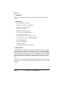
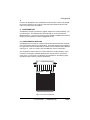
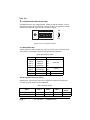
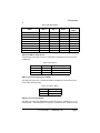
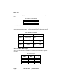
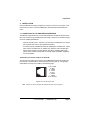
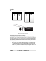
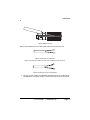
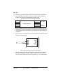
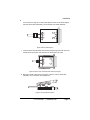
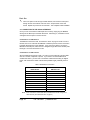
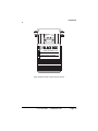
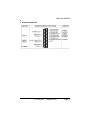
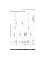
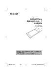
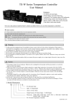
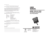
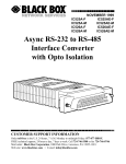
ME670A
Multi-Function Line Driver, DB25
Black Box
TABLE OF CONTENTS
1. Overview ...........................................................................................................5
1.1 Features ................................................................................................5
1.2 Description ............................................................................................5
2. Configuration ....................................................................................................6
2.1 Configuration Switches .........................................................................6
2.2 Configuration Switch Settings ...............................................................7
2.3 Switch Set SW1 ....................................................................................7
SW1 through SW-4: Data Rate Setting ..............................................7
SW1-5 and SW1-6: Clock Source ......................................................8
SW1-7: Anychronous/Synchronous Mode ..........................................8
SW1-8: Carrier Control Method ..........................................................8
2.4 Switch Set SW2 ....................................................................................9
SW2-1 and SW2-2: Word Length .......................................................9
3. Installation .......................................................................................................10
3.1 Connection to the Twisted Pair Interface ............................................10
Twisted Pair Connection Using RJ-11 OR RJ-45 .............................10
Twisted Pair Connection Using Terminal Blocks ..............................11
3.2 Connection to the RS-232 Interface ...................................................15
Connection to a “DTE” Device ..........................................................15
Connection to a “DCE” Device ..........................................................15
4. Operation ........................................................................................................17
4.1 Front Panel Switches ..........................................................................17
4.2 LED Status Monitors ...........................................................................17
4.3 V.54 Test Modes .................................................................................17
Local Analog Loopback (LAL) ...........................................................17
Remote Digital Loopback (RDL) .......................................................18
Using the V.52 BER Test Independently ..........................................18
4.4 Power-Down .......................................................................................19
A. Compliance ....................................................................................................20
A.1 EMC ....................................................................................................20
A.2 Low Voltage Directive (Safety) ............................................................20
A.3 Radio and TV Interference (FCC Part 15) ...........................................20
A.4 CE Declaration of Conformity ..............................................................20
B. Black Box ME670A Specifications .................................................................21
C. Black Box ME670A ........................................................................................22
D. Black Box ME670A Block Diagram ................................................................23
Page 2
724-746-5500 | blackbox.com
RADIO FREQUENCY INTERFERENCE STATEMENTS
FEDERAL COMMUNICATIONS COMMISSION AND INDUSTRY CANADA RADIO
FREQUENCY INTERFERENCE STATEMENTS
This equipment generates, uses, and can radiate radio-frequency energy, and if not
installed and used properly, that is, in strict accordance with the manufacturer’s
instructions, may cause interference to radio communication. It has been tested and
found to comply with the limits for a Class A computing device in accordance with the
specifications in Subpart B of Part 15 of FCC rules, which are designed to provide reasonable protection against such interference when the equipment is operated in a
commercial environment. Operation of this equipment in a residential area is likely to
cause interference, in which case the user at his own expense will be required to take
whatever measures may be necessary to correct the interference.
Changes or modifications not expressly approved by the party responsible for compliance could void the user’s authority to operate the equipment.
This digital apparatus does not exceed the Class A limits for radio noise emission from
digital apparatus set out in the Radio Interference Regulation of Industry Canada.
Le présent appareil numérique n’émet pas de bruits radioélectriques dépassant les
limites applicables aux appareils numériques de la classe A prescrites dans le Règlement sur le brouillage radioélectrique publié par Industrie Canada.
724-746-5500 | blackbox.com
Page 3
Black Box
1. OVERVIEW
This section provides a gerneral list of features and a description of the Black Box
product.
1.1 FEATURES
• Switch-selectable carrier control
• Synchronous or asynchronous operation
• No AC power or batteries required
• Data rates to 38.4 Kbps
• Distances to 12 miles (19.2 km)
• Point-to-point or multipoint operation
• Full or half duplex operation
• Internal, external or received loopback clocking
• V.54 loopback tests and V.52 compliant BER tests
• Automatic equalization
• Easy-to-read status LEDs
• Transformer isolation
• Silicon Avalanche Diode surge protection
1.2 DESCRIPTION
The ME670A carrier controlled short range modem supports synchronous and asynchronous data rates to 38.4 Kbps. Requiring no AC power or batteries, the ME670A
supports distances to 12 miles over unconditioned twisted pair. The ME670A features
front panel LEDs, automatic equalization, V.52 compliant BER tests, both internal and
external clocking and V.54 loopback tests. Built-in transformer isolation and surge protection provide protection against ground potential differences and AC/DC over-voltages.
The ME670A is fully compatible with the Black Box Model ME475A-R2. This compatibility allows you to combine miniature, standalone and rack mounted modems in a single system.
Page 4
724-746-5500 | blackbox.com
Configuration
Housed in an ABS plastic case, the ME670A comes with either a male or female DB25 connector and both an RJ-11/RJ-45 combo jack and terminal blocks with strain
relief. The combo jack is pre-installed.
2. CONFIGURATION
The ME670A is simple to install and is ruggedly designed for excellent reliability: just
set it and forget it. The following instructions will help you set up and install the
ME670A properly. If you have any questions, don’t hesitate to call Black Box Technical
Support at (724) 746-5500 or email to [email protected].
2.1 CONFIGURATION SWITCHES
The ME670A uses a unique set of sixteen external DIP switches that allow configuration to an extremely wide range of applications. These DIP switches are grouped into
two eight-switch sets and are externally accessible from the underside of the ME670A
(see Figure 1). There is no need to open the ME670A’s case for configuration.
The configuration switches allow you to select data rates, clocking methods, V.52 &
V.54 tests, word lengths, extended signaling rates, asynchronous or synchronous
mode and 2- or 4-wire mode. The drawings, text and tables on the following pages
describe all switch locations, positions and functions.
1 2 3 4 5 6 7 8
1 2 3 4 5 6 7 8
OFF
OFF
SW1
SW2
Figure 1. The back of the ME670A
724-746-5500 | blackbox.com
Page 5
Black Box
2.2 CONFIGURATION SWITCH SETTINGS
The ME670A has two sets of eight switches, yielding 16 total DIP switches. The two
sets will be referred to as SW1 and SW2. As Figure 2 shows, the orientation of all DIP
switches is the same with respect to “ON” and “OFF” positions.
ON
DHS-8
1 2 3 4 5 6 7 8
OFF
OFF
Figure 2. Close up of cofiguration switches
2.3 SWITCH SET SW1
The DIP switches on SW1 set data rate, clock source, async./sync. mode and carrier
control method. The default settings are summarized in the table below.
Table 2. SW1
Summary Table
Position
Function
SW1-1
SW1-2
SW1-3
SW1-4
SW1-5
SW1-6
SW1-7
SW1-8
Data Rate
Data Rate
Data Rate
Data Rate
Clock Source
Clock Source
Async./Sync.
Carrier Control
Factory Default
On
Off
Off
On
On
On
On
Off
9,600 bps
Internal
Async,
Constantly On
SW1 through SW-4: Data Rate Setting
Switches SW1-1 through SW1-4 are set in combination to determine the asynchronous and synchronous data rate for the ME670A.
Table 3: Data
Page 6
Rate Setting
SW1-1
SW1-2
SW1-3
SW1-4
Setting
(Kbps)
On
Off
On
On
On
On
On
On
1.2
1.8
724-746-5500 | blackbox.com
Configuration
Table 3: Data
Rate Setting
SW1-1
SW1-2
SW1-3
SW1-4
Setting
(Kbps)
On
Off
On
Off
On
Off
On
Off
On
Off
Off
On
On
Off
Off
On
On
On
On
On
Off
Off
Off
Off
Off
On
On
On
On
On
On
On
On
Off
Off
Off
2.4
3.6
4.8
7.2
9.6
14.4
19.2
28.8
38.4
SW1-5 and SW1-6: Clock Source
Switches SW1-5 and SW1-6 are set in combination to determine the clock source for
the ME670A.
Table 4: Clock
Source
SW1-5
SW1-6
Setting
On
Off
On
On
On
Off
Internal Transmit clock
Receive Recover Clock
External Transmit Clock
SW1-7: Anychronous/Synchronous Mode
The setting for switch SW1-7 determines whether the ME670A is in asynchronous or
synchronous operating mode.
Table 5: Anyc./Sync.
Mode
SW1-7
Setting
On
Off
Anychronous
Synchronous
SW1-8: Carrier Control Method
The setting for switch SW1-8 determines whether the carrier is “constantly on” or “controlled by RTS”. This setting allows for operation in switched carrier, multipoint and/or
724-746-5500 | blackbox.com
Page 7
Black Box
hardware handshaking applications. Note: SW1-8 must be “ON” in all 2-wire applications.
Table 6: Carrier
Control Method
SW1-8
Setting
Off
On
Constantly on
Controlled by RTS
2.4 SWITCH SET SW2
The DIP switches on SW2 set word length, extended signaling rate, RTS/CTS delay,
2-wire/4-wire and V.52/V.54 tests. The factory default settings for Switch Set SW2 are
summarized in the table below.
Table 7: SW2
Summary Table
Position
Function
SW2-1
SW2-2
SW2-3
SW2-4
SW2-5
SW2-6
SW2-7
Word Length
Word Length
Extended Signaling
RTS/CTS Delay
RTS/CTS Delays
2/4 Wire
2/4 Wire
Off
Off
Off
On
On
On
Off
Factory Default
SW2-8
V.52/V.54 Tests
Off
10 bits
-2.5% to +1%
7 mS
4-wire/
full dpx
Enabled
SW2-1 and SW2-2: Word Length
SW2-1 and SW2-2 are set in combination to determine the word length for aynchronous data.
Table 8: Word
Page 8
Length
SW2-1
SW2-2
Setting
(bits)
Off
On
Off
On
On
On
Off
Off
8
9
10
11
724-746-5500 | blackbox.com
Installation
3. INSTALLATION
Once the ME670A is properly configured, it is ready to connect to your system. This
section tells you how to connect the ME670A to the twisted pair and RS-232 interfaces.
3.1 CONNECTION TO THE TWISTED PAIR INTERFACE
The ME670A supports data-only communication between two RS-232 devices at distances to 12 miles (19.2) and data rates to 38.4 Kbps. There are two essential requirements for installing the ME670A:
• These units work in pairs. Therefore, you must have one ME670A (or a compatible model) at each end of a two twisted pair interface.
• To function properly, the ME670A needs two twisted pairs of metallic wire. These
pairs must be unconditioned, dry, metallic wire, between 19 and 26 AWG (the
higher number gauges may limit distance somewhat). Standard dial-up telephone circuits or leased circuits that run through signal equalization equipment
are not acceptable.
Twisted Pair Connection Using RJ-11 OR RJ-45
The RJ-11/RJ-45 combo jack connectors on the ME670A's twisted pair interface are
pre-wired for a standard TELCO wiring environment (see Figure 3). The signal/pin
relationships are shown on the table on the following page.
1- No Contact
2 - Blue
3 - Yellow
4 - Green
5- Red
6 - Black
7 - White
8 - No Contact
Figure 3. RJ-11/RJ-45 Combo Jack
Note
Both RJ-11 and RJ-45 plugs will insert into the jack, shown in Figure 3.
724-746-5500 | blackbox.com
Page 9
Black Box
Table 9. Plug
Wiring
RJ-11
Signal
RJ-45
Signal
1
2
3
GND*
RCV*
XMT
1
2
3
N/C
GND*
4
5
6
XMT
RCV
GND*
4
5
6
7
8
RCVXMT
XMT
RCV
GND*
N/C
Figure 4. Inserting flathead screwdriver
Twisted Pair Connection Using Terminal Blocks
If your application requires you to connect two pairs of bare wires to the ME670A, you
must open the case to access the terminal blocks. For your convenience, the ME670A
comes standard with a RJ-11/RJ-45 combo jack and a terminal block with strain relief.
The instructions on the following pages will tell you how to open the case, connect the
bare wires to the terminal blocks and fasten the strain relief collar in place so that the
wires won't pull loose.
1. Open the unit by gently inserting a flathead screwdriver into the special pry slot
on the plastic case (below). Don't worry about breaking the plastic, but make
sure that you do not insert the screwdriver more than 1/4” into the enclosure, as
you may damage the unit.Once the unit has been opened, you will be able to see
the terminal blocks located at the rear of the PC board.
Page 10
724-746-5500 | blackbox.com
Installation
Figure 5. ME670A opened
Strip the outer insulation from the twisted pairs about one inch from the end.
Figure 6. Twisted pair pre-modification
Figure 7. Strip back the insulation on each of the 2 twisted pair wires about.25”.
Figure 8. Twisted pair wires post modefication
2. Connect one pair of wires to the two XMT (transmit) poles on the terminal block.
The ME670A is not polarity sensitive, so either wire may connect to either pole.
724-746-5500 | blackbox.com
Page 11
Black Box
3. Connect the other pair of wires to the two RCV (receive) poles on the terminal
block. Ultimately, you will want to construct a two-pair crossover cable that
makes a connection with the two ME670As as shown below:
Table 10: Two-pair
XMT
XMT
G
RCV
RCV
Crossover Cable Connections
To Shield (Optional)
RCV
RCV
G
XMT
XMT
One Pair
One Pair
4. If there is a shield around the telephone cable it may be connected to “G” on the
terminal block. To avoid ground loops, we recommend connecting the shield at
the computer end only. A ground wire is not necessary for proper operation of
the ME670A.
5. When you finish connecting the wires to the terminal block, the assembly should
resemble the diagram below:
XMT G RCV
Figure 9. Two-Pair Crossover Cable Connection Diagram
6. Place the 2 halves of the strain relief assembly on either side of the telephone
wire and press together very lightly. Slide the assembly so that it is about 2
inches from the terminal posts and press together firmly. If your cable diameter
Page 12
724-746-5500 | blackbox.com
Installation
is too small or too large for our strain relief, please contact our technical support.
We have strain relief assemblies to accommodate most cable diameters.
XMT G RCV
Figure 10. Strain Relief Diagram
7. Insert the strain relief assembly with the wire going through it into the slot in the
bottom half of the modem case and set it into the recess in the case.
XMT G
RCV
Figure 11. Recess Case with Strain Relief Assembly Diagram
8. Bend the top half of the case as necessary to place it over the strain relief
assembly. Do not snap the case together yet.
Figure 12. Closing ME670A Chassis
724-746-5500 | blackbox.com
Page 13
Black Box
9. Insert one captive screw through a saddle washer, then insert the entire piece
through the hole in the DB-25 end of the case. Snap that side of the case
closed. Repeat the process for the other side. This completes cable installation.
3.2 CONNECTION TO THE RS-232 INTERFACE
Once you have connected the twisted pair wires correctly, simply plug the ME670A
directly into the DB-25 port of the RS-232 device. After doing so, remember to insert
and tighten the two captive connector screws.
Connection to a “DTE” Device
The ME670A is wired as a DCE, and therefore “wants” to plug into a DTE such as a
terminal, PC or host. Because the ME670A is interface powered, a direct connection
to the RS-232 DTE port is most desirable. If you must use a cable to connect the
ME670A to the DTE port, make sure it is a straight through cable of the shortest possible length—we recommend 6 feet or less.
Connection to a “DCE” Device
Since the ME670A is wired as a DCE, you cannot connect it directly to another DCE
such as a modem, multiplexer or printer. If you need to connect the ME670A to
another DCE device, you must use a null modem cable wired according to diagram
below. We recommend a cable of the shortest possible length, preferably 6 feet or
less.
Table 11: DCE
Note
Page 14
Device Connection
Connection to ME670A
DB-25 Pin No.
Connection to DCE Device
DB-25 Pin No.
1
2
3
4
8
6
20
17
24
7
1
3
2
8
4
20
6
24
17
7
When connected to another DCE deice, the ME670A should be configured for
“external clock” (see “Switch Set SW1” on page 6)
724-746-5500 | blackbox.com
Installation
BERT
LOOP
511/RDL
NORMAL
511 LAL
ME670A
Multi-Function Line Driver
S/N 123456
Figure 13. ME670A’s LED indicators and test switches
724-746-5500 | blackbox.com
Page 15
Black Box
4. OPERATION
Once the ME670A is properly configured and installed, it should operate transparently—as if it were a standard cable connection. Operating power is derived from the
data and control signals; there is no “ON/OFF” switch. This chapter describes reading
the LED status monitors, powering-up and using the built-in V.52 and V.54 test modes.
4.1 FRONT PANEL SWITCHES
During normal operation, both front panel switches should be in the “normal” center
position. To operate a test mode, see “V.54 Test Modes” on page 16.
4.2 LED STATUS MONITORS
The ME670A features 2 front panel LEDs that indicate the condition of the V.52 and
V.54 test modes. figure 13 on page 15 shows the location of each LED. “V.54 Test
Modes” describes each LED’s function in more detail.
4.3 V.54 TEST MODES
The ME670A offers two V.54 test modes to evaluate the condition of the modems and
the communication link. These tests can be activated physically from the front panel,
or via the RS-232 interface. Note: V.54 test modes on the ME670A are available for
point-to-point and 4-wire applications only.
Local Analog Loopback (LAL)
The Local Analog Loopback (LAL) test checks the operation of the local ME670A, and
is performed separately on each unit. Any data sent to the local ME670A in this test
mode will be echoed (returned) back to the user device. For example, characters
typed on the keyboard of a terminal will appear on the terminal screen. To perform a
LAL test, follow these steps:
1. Activate LAL. This may be done in one of two ways: First, by moving the front
panel toggle switch DOWN to “LAL”. Second, by raising pin 18 on the RS-232
interface (Note: Make sure DIP switch SW2-8 is OFF). Once LAL is activated,
the ME670A transmit output is connected to its own receiver. The “test” LED
should be lit.
2. Verify that the data terminal equipment is operating properly and can be used for
a test. If a fault is indicated, call a technician or replace the unit.
3. Perform a BER (bit error rate) test on each unit. If the BER test equipment indicates no faults, but the data terminal indicates a fault, follow the manufacturer’s
Page 16
724-746-5500 | blackbox.com
Operation
checkout procedures for the data terminal. Also, check the RS-232 interface
cable between the terminal and the ME670A.
Remote Digital Loopback (RDL)
The Remote Digital Loopback (RDL) test checks the performance of both the local and
remote ME670As and the communication link between them. Any characters sent to
the remote ME670A in this test mode will be returned back to the originating device.
For example, characters typed on the keyboard of the local terminal will appear on the
local terminal screen after having been passed to the remote ME670A and looped
back. To perform an RDL test, follow these steps:
1. Activate RDL. This may be done in two ways: first, by moving the front panel
toggle switch UP to “RDL”. Second, by raising pin 21 on the RS-232 interface
(Note: Make sure SW2-8 is OFF).
2. Perform a BER (bit error rate) test on the system.
3. If the BER test equipment indicates a fault, and the Local Analog Loopback test
was successful for both ME670As, you may have a problem with the twisted pair
line between the modems. Make sure you check the twisted pair line for proper
connections and continuity.
Using the V.52 BER Test Independently
The V.52 BER test can be used independently of the V.54 loopback tests. This
requires two operators: one to initiate and monitor the test at the local ME670A, and
one at the remote ME670A. To use the V.52 BER test by itself, both operators should
simultaneously follow these steps:
1. Locate the “511/511E” toggle switch on the front panel of the 1040 and move it
DOWN. This activates the V.52 BER test mode and transmits a “511” test pattern to the other unit. If any errors are present, the receiving modem’s red “Error”
LED will blink sporadically. Note: For this test to function, the “511” switch on
both ME670As must be on.
2. If the test indicates no errors are present, move the V.52 toggle switch UP, activating the “511/E” test with periodic errors present. If the test is working properly,
the receiving modem's red “Error” LED will light continuously. A successful
“511/E” test will confirm that the link is in place, and that the ME670A’s built-in
“511” generator and detector are working properly.
724-746-5500 | blackbox.com
Page 17
Black Box
4.4 POWER-DOWN
Turn off the ME670A by simply removing it from the circuit or by turning off the terminal
that is directly connected to the ME670A.
Page 18
724-746-5500 | blackbox.com
Compliance
A. COMPLIANCE
A.1 EMC
• FCC Part 15, Class A
• EN55022, Class A
• EN ETSI 300 386 V1.3.3
A.2 LOW VOLTAGE DIRECTIVE (SAFETY)
• UL 60950-1/CSA C22.2 No. 60950-1
• IEC/EN60950-1
A.3 RADIO AND TV INTERFERENCE (FCC PART 15)
This device generates and uses radio frequency energy, and if not installed and used
properly-that is, in strict accordance with the manufacturer’s instructions-may cause
interference to radio and television reception. The device has been tested and found to
comply with the limits for a Class A computing device in accordance with specifications
in Subpart B of Part 15 of FCC rules, which are designed to provide reasonable protection from such interference in a commercial installation. However, there is no guarantee that interference will not occur in a particular installation. If the device does cause
interference to radio or television reception, which can be determined by disconnecting
the unit, the user is encouraged to try to correct the interference by one or more of the
following measures: moving the computing equipment away from the receiver, re-orienting the receiving antenna and/or plugging the receiving equipment into a different
AC outlet (such that the computing equipment and receiver are on different branches).
A.4 CE DECLARATION OF CONFORMITY
Black Box, Corporation declares that this device is in compliance with the essential
requirements and other relevant provisions of Directive 2004/108/EC relating to electromagnetic compatibility and Directive 2006/95/EC relating to electrical equipment
designed for use within certain voltage limits. Contact [email protected] for a Declaration of Conformity.
The safety advice in the documentation accompanying this device shall be obeyed.
The conformity to the above directive is indicated by CE mark on the device.
724-746-5500 | blackbox.com
Page 19
Black Box
B. BLACK BOX ME670A SPECIFICATIONS
Table 12. ME670A
Specifications
Transmission Format
Sync. and asyn., full or half duplex
Transmission Line
Unconditioned twisted pair 19-26 AWG
Clocking
Internal, external, or receive loopback
Interfaces
EIA RS-232, CCITT V.24
Data Rates
1.2, 1.8, 2.4, 3.6, 4.8, 7.2, 9.6, 14.4, 19.2, 28.8, 34.4
Kbps (switch selectable)
Isolation
Minimum 1500 V RMS via isolation transformers
Control signals
Constantly “on” or controlled by RTS
RTS/CTS Delay
No delay, 7ms, 53ms
Connectors
DB-25 male or female on RS-232 side; RJ-11, RJ-45 or
terminal block with strain relief on line side
Power Supply
None required; uses power from EIA data and control
signals
Surge Protection
Compliant with IEC 801.5 level 2, 1kV
Temperature Range
0-60 C (32-140 F)
Altitude
0-15,000 feet
Humidity
5 to 95% non-condensing
Dimensions
3.0” x 2.1” x 0.81” (7.6 x 5.3 x 2.1 cm)
Weight
2 oz. (56.7g)
Page 20
724-746-5500 | blackbox.com
Black Box ME670A
C. BLACK BOX ME670A
724-746-5500 | blackbox.com
Page 21
Black Box ME670A Block Diagram
D. BLACK BOX ME670A BLOCK DIAGRAM
724-746-5500 | blackbox.com
Page 22
ME670A version 1