1
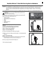
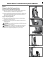
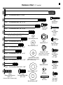
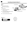
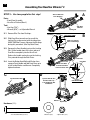
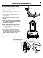
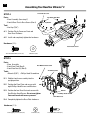
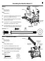
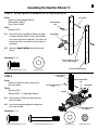
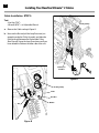
The Bowflex Ultimate 2
Assembly Instructions
®
(Shown with optional accessories)
WWWBOWFLEXCOM
000-4300-092308C
1
Congratulations
Congratulations on your commitment to improving your health and fitness! With the Bowflex Ultimate® 2 home
gym, you have everything you need to exceed all of your physical fitness, strength and health expectations!
The Bowflex Ultimate® 2 home gym’s exceptional resistance and quality is unmatched by any other single piece
of home fitness equipment available. You will not believe the amazing results your body will get with the Bowflex
Ultimate® 2 home gym!
With all of the fitness choices available today, finding the best workout equipment for your needs can be confusing.
Everyone at Nautilus would like to congratulate you and thank you for selecting the Bowflex Ultimate® 2 home
gym.
The Bowflex Ultimate® 2 home gym is the best home fitness product available, and you’re just about to prove it to
yourself.
Assembly Guide Table of Contents
Bowflex Ultimate® 2 Seat Rail Securing Device..2
Installing Your Bowflex Ultimate® 2 Accessories
Before You Start......................................................5
Squat Attachment............................................41
Bowflex Ultimate® 2 Parts Reference Guide.......6
Leg Extension...................................................43
Parts List...................................................................7
Leg Extension Seat..........................................44
Tools You Will Need..............................................15
Preacher Curl...................................................44
Hardware Chart.....................................................16
Bench................................................................45
Assembling Your Bowflex Ultimate® 2 Gym......17
Ab Crunch Attachment...................................45
Installing Your Bowflex Ultimate® 2 Cables.......35
DVD Player.......................................................46
Bowflex Ultimate 2 Seat Rail Securing Device Addendum
®
NOTICE: T
his Addendum provides important instructions for securing the Bowflex Ultimate® 2 Home
Gym Seat Rail to the Seat Rail Securing Device. Be aware that the Owner’s and Assembly
Manuals refer to the Seat Rail Securing Device as the "Squat Holder" and/or "rail securing
device".
If you need assistance, please call Bowflex® Customer Service at 1-800-628-8458.
WARNING Failure to secure the Seat Rail Securing Device into
the Seat Rail may cause injury.
It is important to latch the Seat Rail Securing Device into the Seat Rail
before performing the following exercises:
•
•
•
•
•
•
Standing Lat Row
Standing Biceps Curl (with pulleys)
Squat
Lunge
Standing Calf Press
Wide Squat
Figure 1
Part A
Latch the Seat Rail Securing Device
Step 1: Remove the Seat Back
Step 2: Lock the Sliding Seat
2-1 Seat must be locked at the end of the Seat Rail.
Figure 2
2-2 Make sure that the sliding seat lock handle is in the locked position
(Figure 1).
Step 3: Lift the Seat Rail
3-1 Bend at the knees and grab the Seat Rail with one hand and the
locked Sliding Seat with your other hand (Figure 2).
3-2 Use your legs to lift the Seat Rail (Figure 3).
(Part A continued on page 2)
Figure 3
2
3
Bowflex Ultimate® 2 Seat Rail Securing Device Addendum
Part A (continued)
Step 4: Latch the Seat Rail Securing Device
4-1Insert the Seat Rail Securing Device into the hole in the Seat Rail
until it clicks (Figures 4, 5, 6).
Step 5: Make sure that the Seat Rail is secured.
5-1 Stand to the side of the machine base and Seat Rail.
WARNING Do not stand on the base below the Seat Rail when you
pull on it. This may cause injury.
5-2Pull down on the Seat Rail to make sure that the Seat Rail Securing
Device is secured (Figure 7).
Figure 4
Seat Rail
Securing
Device
Seat Rail
Figure 5
Figure 6
Figure 7
Bowflex Ultimate 2 Seat Rail Securing Device Addendum
®
Part B
Release the Seat Rail Securing Device
Step 1: Secure the Seat Rail Securing Device
1-1 W ith your inside foot on the machine base, hold the Seat Rail with
one hand and push your shoulder into it lightly (Figure 8).
1-2 Continue to hold the Seat Rail with one hand and your shoulder. Use
your free hand to unlock the Seat Rail Securing Device (Figures 8
and 9) until it releases (Figure 10).
Step 2: Lower the Seat Rail
2-1 W hen the Seat Rail Securing Device releases, use both hands to
hold onto the Seat Rail (Figure 11).
Figure 8
2-2 Use both hands to carefully lower the seat down into the horizontal
position (Figure 12).
WARNING Do not stand on the base below the Seat Rail when you
lower it. This may cause injury.
WARNING Always use both hands to lift and lower the Seat Rail.
Bend at the knees when lifting or setting down the Seat Rail.
Failure to use proper lifting techniques may cause injury.
Figure 9
Figure 10
Figure 11
Figure 12
4
5
Before You Start
Before You Assemble
Select where you are going to locate your Bowflex
Ultimate® 2 home gym carefully. The best place for
your home gym is on a hard, level surface. For best
results, assemble your home gym in the location where
you intend to use it. Allow a workout area of at least
8’4”L x 6’6”W (2.6m L x 2m W) of free space for safe
operation of the Bowflex Ultimate® 2 home gym.
A minimum of 7’4” of ceiling height will be required to
assemble your Bowflex Ultimate® 2 home gym.
Basic Assembly Principles
Here are a few basic tips that will make your assembly
of the Bowflex Ultimate® 2 home gym quick and easy.
By using these principles, you can simplify each process
and save yourself extra time and effort.
1. To make the assembly process go faster,
gather the pieces you need for each step and
thoroughly read the assembly instructions for
that step prior to starting assembly for the step.
2. When tightening a locknut on a bolt, use a
combination wrench to grip the locknut and
ensure that it is fastened securely.
3. When attaching two pieces, gently lift and look
through the bolt holes to help guide the bolt
through the holes.
4. As a general rule, and for all bolts and nuts on
your Bowflex Ultimate® 2 home gym, turn bolts
or nuts toward the right to tighten and left to
loosen.
NOTE: Leave all Cables wrapped and bagged until your
Bowflex ULTIMATE® 2 is fully assembled.
6
Bowflex Ultimate 2 Parts Reference Guide
®
Lat Bar Rests
Vertical Main Frame
Lat Bar
Rod Hook
Cable
Bench
Adjustable
Pulley System
Preacher Curl
Attachment
Pulley Frame
Rod Box
Seat
Pulley
Hand Grip/
Ankle Cuff
Leg Extension/
Leg Curl Attachment
Spring Lock
Seat Pin
Squat
Attachment
Seat Rail
Preacher Curl
Attachment
Standing/Squat Platform
Ab Curl
Attachment
(optional)
7
Box Contents / Parts List
BOX 1
1
Box 1 Contents
Reference #
Qty.
1
1
Description
210 lb. Rod Pack
8
Box Contents / Parts List
BOX 2
3
5
6
4
8
2
9
7
Box 2 Contents
Reference #
2
3
4
5
6
7
8
9
Qty.
1
1
1
1
2
1
1
1
Description
Rear Base Assembly
Right Squat Assembly Handlebar
Left Squat Assembly Handlebar
Squat Frame
Squat Assembly Pad
Front Plastic Cover
Right Rear Plastic Cover
Left Rear Plastic Cover
9
Box Contents / Parts List
BOX 3
13
14
10
12
11
Box 3 Contents
Reference #
10 11 12 13 14 Qty.
1
1
1
2
2
Description
Front Base Assembly
Front Base Plate
Front Handle Assembly
Single Pulley Assembly With Two Cheeks
Leg Extension Pulley Bracket
10
Box Contents / Parts List
BOX 4
23
26
21
20
16
19
17
18
22
24
25
15
Box 4 Contents
Reference #
15 16 17 18 19 20 21 22 23 24 25 26 Qty.
2
2
2
2
2
1
1
1
1
1
1
1
Description
Side Plate
Floating Pulley assembly
Single Pulley Assembly With Two Cheeks
Pulley
Pulley Slider
Cross Brace
Washer Plate
Squat Holder
Right Lower Upright
Left Lower Upright
Rod Box (Rod Box Retainer is located on hardware card)
Chest Bar
11
Box Contents / Parts List
BOX 5
27
32
28
33
29
34
35
30
36
Box 5 Contents
Reference #
27 28 29 30 31 32 33 34 35 36 31
Qty.
1
1
4
2
2
2
1
1
2
1
Description
Lat Pull Down Bar
Bench
Plastic Foot
Grip Ankle Cuff
Hand Grip
Foot Harness
Foot Harness Instructions
Seat Rail With Sliding Seat
Hardware Cards
Rowing Belt
12
Box Contents / Parts List
BOX 6
37
39
38
40
41
43
42
44
Box 6 Contents
Reference #
37 38 39 40 41 42 43 44 Qty.
1
1
1
1
1
1
1
1
Description
Top Plate
Right Lat Boom
Left Lat Boom
Lat Bar With Pulley Sliders
Rear Pulley Frame
Face Plate
Left Upper Lat Upright
Right Upper Lat Upright
13
Box Contents / Parts List
BOX 7
46
45
48
47
49
50
51
52
53
54
Box 7 Contents
Reference #
45 46 47 48 49 50 51 52 53 54 Qty.
1
1
1
1
1
1
2
1
1
1
Description
Leg Extension Seat Frame
Leg Extension Seat Pad
Preacher Curl Pad
Hardware Bag
Preacher Curl Bar
Preacher Curl Frame
Roller Pad
Leg Extension Assembly
Webbing With Steel Rings
Leg Extension Roller Shaft
14
Box Contents / Parts List
Ab Box
55
63
56
57
58
59
60
61
Ab Box Contents
Reference #
Qty.
55 1
56 1
57 1
58 1
59 1
60 1
61 1
62 1
63 2
62
Description
Ab Crunch Middle pad
Ab Crunch Handle Bar
Hardware Bag
Ab Crunch Roller Shaft
Ab Crunch Pivot Arm
Ab Crunch Frame
Ab Cable Hook
Ab Crunch Back Pad
Ab Cruch Roller Pads
15
Tools You Will Need
Hex Wrenches Are Provided in the Box
3/16” Hex Key for 5/16” Pan Head Allen Bolts :
7/32” Hex Key for 3/8” Pan Head Allen Bolts :
5/32” Hex Key for #10 Cap Screws :
These Tools Are Not Provided in the Box
Wrench (1/2”), (7/16”), (9/16”) and (3/4”) or Adjustable Wrench
(not provided):
Phillips Head Screwdriver (not provided):
* Specifications subject to change without notice.
NOTE: the rod box retainer (with 2 pre-installed
screws) is located on the hardware card.
16
Hardware Chart (1:1 scale)
1TY 0AN(EAD!LLEN"OLTvXv
1TY
#AP3CREWS
Xv
1TY 0AN(EAD!LLEN"OLTvXv
1TY
#AP3CREW
Xv
1TY 0AN(EAD!LLEN"OLTvXv
1TY 0AN(EAD!LLEN"OLTvXv
,OCATEDIN!B"OXHARDWAREBAG
1TY
3ELF4APPING
3CREWS
Xv
1TY7ASHERS
1TY 0AN(EAD!LLEN"OLTvXv
1TY
.YLOCK.UTv
1TY7ASHERSv
1TY 0AN(EAD!LLEN"OLTvXv
1TY
.YLOCK.UTv
4WOOFTHESEARELOCATED
IN!BBOXHARDWAREBAG
1TY 0AN(EAD!LLEN"OLTvXv
1TY7ASHERSv
1TY 0AN(EAD!LLEN"OLTvXv
1TY
3ELF4APPING
3CREWS
vXv
%IGHTOFTHESEARELOCATEDIN
"OXHARDWAREBAG
1TY
.YLOCK.UTv
1TY 0AN(EAD!LLEN"OLTvXv
1TY7ASHERSv
1TY
"UTTON(EAD3CREWS
vXv
1TY
#OACH3CREWS
Xv
1TY
0AN(EAD!LLEN"OLT
vXv
,OCATEDIN"OXHARDWAREBAG
1TY7ASHERSv
1TY
3ELF4APPING
3CREWS
Xv
1TY
.UT
1TY
0INS
1TY
0AN(EAD
!LLEN"OLT
vXv
17
Assembling Your Bowflex Ultimate® 2
STEP 1
Front Base Platform
Parts:
• Front Base Platform (Box 3)
• Metal Handle Assembly (Box 3)
Tools:
• Hex Key (7/32”)
Cable Ends
1-1 Move twist ties and cable ends
up and out of the way.
Pan Head Allen Bolt
Metal Handle Assembly
1-2 P
osition the Metal Handle Assembly (Label side
up) on the Front Base Platform.
1-3 Install and completely tighten the hardware.
Hardware (1:1):
2 Pan Head Allen Bolt (3/8” X 2 1/4”)
2 Washers (3/8”)
18
Assembling Your Bowflex Ultimate 2
®
STEP 2
Parts:
• Handle and Base Assembly (from Step 1)
• Plastic Handle Top and Bottom
• Cable Retainer Pins (Hardware Card)
• Plastic Plug Covers
Front Handle
Tools:
• Hex Key (5/32”)
2-1 Lay the Handle and Base Assembly down on the
floor, remove the Plastic Plug Covers and
separate the Top and Bottom of the Plastic Handle.
Plastic Plug Cover (N)
Plastic Plug Cover (H)
Plastic Handle
Top
Cap Screw
2-2 Remove the Twist Ties.
2-3 Feed cables through Metal Handle and position
the Cable End Loop just inside the Hollow Tube.
You may have to slide the Hollow Tube toward
the Front Base to allow cables to reach.
2-4 I nsert Cable Retainer Pins through hole and
cable loop. (See Detail A)
Cable Retainer Pin
Hollow Tube
Plastic Handle
Bottom
Plastic Plug Cover (H)
2-5 Position Top and Bottom of Plastic Handle.
NOTE: T he hexagonal holes in the left side of the
Handle are shallower than the holes in the right
side. The #10 Nuts go in the deeper hexagonal
holes on the right side of the handle. The right
side can be identified by noting a small hole in
the plastic flange. (See Detail B)
Nut #10
Plastic Plug Cover (N)
Cable Retainer Pin through
hole and Cable End Loop
2-6 Install and completely tighten the hardware.
2-7 Install Plastic Plug Covers over hardware.
NOTE: The Plug Covers are marked on the inside with
an “N” or an “H”. To insure proper fit, use the
caps marked with an “N” to cover the nuts
and the caps marked with an “H” to cover the
screw heads.
Detail A
Note small hole in Handle
on Right side
Hardware (1:1):
2 Cap Screws (#10 X 1”)
2 Nut (#10)
2 5.27 Cable Retainer Pins
Detail B
Deeper Hole
19
Assembling Your Bowflex Ultimate® 2
STEP 3 – Use two people for this step!
Parts:
• Front Base Assembly
• Rear Base Platform (Box 2)
A
Remove Wire Ties
from Bushings
Tool:
• Hex Key (7/32”)
• Wrench (9/16”) - or Adjustable Wrench
Rear Base
Platform
Locking Pin
3-1 Remove Wire Ties from Bushings.
Bushings
3-2 S
lide Front Base toward rear base until the
Locking Pins make contact with the side plates.
MAKE SURE the Flanges slide over the Bushings
during this procedure. (See Top Detail View) Make sure Flanges
slide over Bushings
3-3 S
queeze the Front Handle to retract the Locking
Pins, lift the handle about 3-4 inches and push
Front Base completely into the Rear Base.
Release the handle and make sure the Locking
Pins protrude through the Side Plates.
Side Plate
3-4 I nsert the Button Head Bolt and Washer then
squeeze Front Handle and fold Front Base up to
install Inside Washer and Hex nut. Completely
tighten hardware.
C
Side Plate
Slide Front Base
towards Back Base
Until it Contacts Pins
Locking Pin
D
Pan Head Allen Bolt
Squeeze Handle and
Fold Front Base up
to install Nylock Nut
and Washer
TOP DETAIL VIEW
Washer
Washer
Hardware (1:1):
2 Pan Head Allen Bolt (3/8” X 3”)
B
TOP DETAIL VIEW
4 Washers (3/8”)
Nylock Nut
2 Nylock Nut (3/8”)
20
Assembling Your Bowflex Ultimate 2
®
The cables that retract the locking pins may
stretch with use. If the locking pins do not fully
retract or interfere with the side plates, make
the following adjustment.
Pull handle and position base
between the locking positions.
Cable Adjustment (Requires Two People)
1. Position the base somewhere between the two
locking positions.
2. Pull the handle until it is in the most compressed
position.
3. Place a 1/4” or adjustable wrench on the Adjusting
Barrel and use a 1/4” or adjustable wrench to loosen
the locking nut. (See Detail B)
4. Rotate the Adjusting Barrel clockwise to increase
the cable tension. The Locking Pins should be as
close to the Side Plates as possible without making
contact. (See Detail A)
5. Test the adjustment by releasing the handle and
rotating the base to a locking hole. Make sure pin
securely engages with the locking hole then pull the
handle and make sure the unit moves freely.
6. Repeat the procedure for both sides if necessary.
7. Tighten Lock Nuts against Adjusting Barrel.
Make sure Locking Pin is as close
as possible without making
contact with Side Plate
Adjusting Barrel
Detail A
Locking Nut
Detail B
21
Assembling Your Bowflex Ultimate® 2
STEP 4
Front Plastic Cover
Pan Head Allen Bolt
Parts:
• Base Assembly (from step 3)
• Front & Rear Plastic Base Covers (Box 2)
Washer
Tool:
• Hex Key (7/32”)
4-1 Position Plastic Covers on Front and
Rear Base Platforms.
4-2 Install and completely tighten the hardware.
Hardware (1:1):
Rear Plastic Cover
9 Pan Head Allen Bolt (1/4” X 1/2”)
9 Washers (1/4”)
STEP 5
Parts:
• Base Assembly
• Front Base Plate (Box 3)
• Front Base Feet (4) (Box 5)
Hex Washer Head Screw
Tools:
• Wrench (5/16”) • Phillips Head Screwdriver
Front Base Plate
5-1 F old the front base assembly into the
upright position.
5-2 P
osition the Base Plate and secure with
eight Phillips Head Screws and Washers.
5-3 P
osition the four Base Feet and secure with
Hex Washer Head Screws. Do not over tighten.
Feet could crack with excess pressure!
Washer
Phillips Head Screw
Front Base Foot
5-4 Completely tighten the Base Plate hardware.
Hardware (1:1):
8 Self Tapping Screws (#8 X 3/4”)
8 Washers (#8 )
4 Coach Screws (#10 X 3/4”)
22
Assembling Your Bowflex Ultimate 2
®
Pan Head Allen Bolt
4 3/4”
STEP 6
Parts:
• Base Assembly
• Rod Box (Box 4)
Rod Box
Tools:
• Hex Key (7/32”)
6-1 L eave Base in folded position and tilt forward to
gain access to bottom of Rear Base.
6-2 P
lace the Rod Box through Rear Base and align
with holes in base frame.
Pan Head Allen
Bolt 3/4”
6-3 I nstall the 4 3/4” screw first to hold the Rod Box in
position then install the four 3/4” screws.
6-4 I nstall the two #8 x 3/4” screws to secure the rear
base covers. Completely tighten all the hardware.
#8 x 3/4” Self
Tapping Screw
Washer
Hardware (1:1):
2 Self Tapping Screws (#8 X 3/4”)
4 Pan Head Allen Bolt (3/8” X 3/4”)
2 Washers (#8)
1 Pan Head Allen Bolt (3/8” X 4 3/4”)
5 Washers (3/8”)
STEP 7 (Requires Two People)
Rod Pack
Parts:
• Base Assembly
• Rod Pack (Box 1)
Align with slot
in Rod Box
Tools:
• Phillips Head Screwdriver
50 Lb. Rods
facing down
7-1 Leave Base in folded position from step 6.
7-2 H
ave one person align the Rod Pack with the slot
in the Rod Box with the 50 Lb. rods facing down.
7-3 Have second person Install and completely
tighten hardware.
Hardware (1:1):
3 Self Tapping Screws (#10 X 1”)
3 Washers (1/4”)
Self Tapping
Screw
Washer
23
Assembling Your Bowflex Ultimate® 2
After installing the Rod Box in Step 7, install the Rod Retainer.
STEP 7B
Parts:
• 1 Rod Box Retainer
Unscrew
Tool:
• Phillips Head Screw Driver
Note: Rod Box screws must be installed before
proceeding.
7B-1 Remove both screws connecting the backing
plate and the face plate (See Figure A).
Figure A
7B-2 S tand facing the rear of the Bowflex Ultimate® 2
unit. Place the backing plate (larger piece), with the
curved side facing up, in between the two right-side
50 lb. rods (See Figure B). Verify that the notched lip
of the backing plate is located in the slot of the Box
Frame.
Backing Plate
7B-3 Match up the face plate (thinner piece) to the backing
plate on the outside of the rod box. Make sure that
the notched lip of both backing plates are touching
and that the holes are aligned.
7B-4 Fasten both screws into the lined up holes (See
Figure C). Tighten until snug and then another
quarter turn.
Rod Box
Figure B
Face Plate
Figure C
Rod Box Retainer (screws are pre-installed)
Notched Lip
Qty: 2
Self Threading Screws (#10 x 1”)
Face
Place
Backing
Plate
Curved Side
Insert into slot of
Rod Box Frame
24
Assembling Your Bowflex Ultimate 2
®
STEP 8 (Do Not Tighten The Hardware For This Step Until Step 9 )
Parts:
• Lower Lat Tower Uprights (Box 4)
• Squat Holder (Box 4)
• Cross Brace (Box 4)
Cross Brace
Pan Head Allen
Bolt
Tool:
• Hex Key (7/32”)
8-1 I nsert Cross Brace and Squat Holder into Lower
Lat Tower Uprights. Make sure the Squat Holder
faces the the front of the Uprights. The label is on
the front and the screw holes are on the back of
the holder.
Squat Holder
8-2 Install but do not tighten the hardware until Step 9.
Label
Hardware (1:1):
The Cross Brace is on the
front of the Uprights
2 Pan Head Allen Bolt (3/8” X 3/4”)
Lower Lat Tower Uprights
2 Washers (3/8”)
Lower Lat Tower
Assembly
STEP 9
Parts:
• Lower Lat Tower Assembly (from step 8)
• Base Assembly
Pan Head Allen Bolt
3/4”
Pan Head Allen Bolt
2 1/2”
Tools:
• Hex Key (7/32”)
• Wrench (9/16”) - or Adjustable Wrench
Nylock Nut
Washer
9-1 P
lace Lower Lat Tower over extrusions on
Base Assembly.
9-2 I nstall and completely tighten the hardware
from steps 8 and 9.
(Rod Pack Not Shown
For Clarity)
Hardware (1:1):
4 Pan Head Allen Bolt (3/8” X 3/4”)
2 Pan Head Allen Bolt (3/8” X 2 1/2”)
8 Washers (3/8”)
2 Nylock Nuts (3/8”)
25
Assembling Your Bowflex Ultimate® 2
STEP 10
(Rod Pack Not Shown
For Clarity)
Parts:
• Seat Rail Assembly (Box 5)
• Base Assembly
Rod Box
Assembly
Hex Nut
Tool:
• Hex Key (7/32”)
• Wrench (9/16”) - or Adjustable Wrench
Seat Rail Assembly
Washer
10-1Align holes on Seat Rail with holes
in Rod Box Assembly.
Pan Head Allen
Bolt
10-2 Install and completely tighten the hardware.
Hardware (1:1):
1 Pan Head Allen Bolt (3/8” X 5 1/2”)
1 Nylock Nut (3/8”) 2 Washers (3/8”)
STEP 11
Parts:
• Chest Bar (Box 4)
• Pulley Sliders (Box 4)
• Washer Plate (Box 4)
Chest Bar
Washer Plate
Pulley Slider
Tools:
• Hex Key (5/16”)
• Wrench (3/4”) - or adjustable wrench
Stop Screw
Hex Nut
Pan Head Allen
Washer
Bolt
11-1 Align holes in Chest Bar, Washer Plate and Lat Tower Uprights.
11-2 Install and completely tighten the Chest Bar hardware.
11-3 Slide the Pulley Sliders on (with pulleys facing up and pull
knob facing the seat rail) then install and tighten the
1/4”x1/2” Stop Screws.
(Rod Pack Not Shown
For Clarity)
Hardware (1:1):
2 Nylock Nut (1/2”)
4 Washers (1/2”)
2 Pan Head Allen Bolt (1/2” X 6 3/4”)
2 Cap Screw (1./4 x 1/2”)
26
Assembling Your Bowflex Ultimate 2
®
NOTE: Before you continue, be sure you have a minimum of 88” (7’4”) of ceiling height to insert the
Upper Lat Assembly into the Lower Base (see step 17).
STEP 12
Pan Head Allen
Parts:
Bolt
• Left Lat Boom (Box 6) • Rear Pulley Frame (Box 6)
• Side Plate (Box 4)
Tool:
• Hex Key (3/16”)
Side View
Left Lat Boom
Plane B
Plane A
Swivel
Washer
Side Plate
12-1 Insert RearPulley Frame into
holes in Left Lat Boom.
Make sure the Pulley Frame
Swivel is parallel to the planes
A and B shown in the Side View.
CORRECT
Plane A
Swivel
12-2 Align holes in Side Plate and Lat Boom.
Plane B
Rear Pulley
Frame
12-3 Install but do not tighten hardware.
Hardware (1:1):
INCORRECT
2 Pan Head Allen Bolt (3/8” X 3/4”)
2 Washers (3/8”)
STEP 13
Lat Bar
Parts:
• Pulley Frame Boom Assembly (from step 12)
• Lat Bar (Box 6)
Pulley Frame, Left Boom
Assembly
Tool:
• Hex Key (3/16”)
13-1 Insert left side of Lat Bar into Left Boom.
13-2 Install but do not tighten hardware.
Hardware (1:1):
1 Pan Head Allen Bolt (3/8” X 3/4”)
1 Washer (3/8”)
Pan Head Allen
Bolt
Washer
27
Assembling Your Bowflex Ultimate® 2
STEP 14
Parts:
• Lat Bar, Boom Assembly (From step 13)
• Right Lat Boom (Box 6)
• Side Plate (Box 4)
Right Side
of Lat Bar
Tool:
• Hex Key (3/16”)
Pulley Frame
Cross Bars
14-1 Align holes in Right Lat Boom with Rear Pulley
Frame Cross Bars and insert right side of Lat Bar
and Pulley Frame Cross Bars into Right Lat Boom.
Right Lat Boom
14-2 Align Side Plate with Right Lat Boom and install
but do not tighten hardware.
Hardware (1:1):
Pan Head Allen
Bolt
Washer
Side Plate
3 Pan Head Allen Bolt (3/8” X 3/4”)
STEP 15
3 Washers (3/8”)
Pan Head
Screw
Pan Head Allen Bolt
Parts:
• Lat Bar, Boom Assembly (From step 14)
• Top Plate (Box 6)
Washer
Top Plate
Tools:
• Hex Key (3/16”)
• Phillips Head Screwdriver
15-1 Align holes in Top Plate with Lat Bar and Booms. 15-2Install but do not tighten hardware.
Hardware (1:1):
2 Pan Head Allen Bolt
(3/8” X 3/4”)
5 Self Tapping Screws
(1/4” X 3/4”)
2 Washers (3/8”)
5 Washers (1/4”)
Assembling Your Bowflex Ultimate 2
®
28
STEP 16
Parts:
• Lat Boom Assembly (from step 15)
• Upper Lat Uprights (Box 6)
Tool:
• Hex Key (7/32”)
• Wrench (9/16”) - or Adjustable Wrench
Washer
Pan Head Allen Bolt
3/8” x 3/4”
16-1 Slide Upper Lat Uprights onto Lat Boom assembly
Pan Head Allen Bolt
3/8” x 2 1/2”
16-2Install but do not tighten the two 3/8” x 3/4” screws
into the top of the uprights.
16-3 Install the two 3/8” x 2 1/4” Screws, Washers and
Nylock Nut through the Side Plates and into the
Uprights.
Washer
16-4 Completely tighten all of the hardware for steps
12 through 16.
Washer
Hex Nut
Upper Lat Uprights
Hardware (1:1):
2 Pan Head Allen Bolt (3/8” X 3/4”)
2 Pan Head Allen Bolt (3/8” X 2 1/2”)
6 Washers (3/8”)
2 Nylock Nut (3/8”)
29
Assembling Your Bowflex Ultimate® 2
STEP 17 – Upper Assembly is very heavy!
Use two people for this step!
Parts:
• Upper Lat Assembly (from step 16)
• Base Assembly (from step 11)
Upper Lat Assembly
Tool:
• Hex Key (7/32”)
(Rod Pack Not Shown
For Clarity)
Pan Head Allen
Bolt
17-1 Insert Upper Lat Uprights into Lower Lat Uprights.
Washer
17-2 Install and completely tighten the hardware.
Base Assembly
Hardware (1:1):
8 Pan Head Allen Bolt (3/8” X 3/4”)
8 Washers (3/8”)
STEP 18
Parts:
• Front Face Plate (Box 6)
• Assembled Unit (from step 17)
Pan Head Allen
Bolt
Tool:
• Hex Key (7/32”)
Washer
18-1 Align holes in Face Plate and Uprights.
18-2 Install and completely tighten hardware.
Hardware (1:1):
4 Pan Head Allen Bolt (3/8” X 3/4”)
4 Washers (3/8”)
Front Face Plate
Lat Tower Uprights
(Rod Pack Not Shown
For Clarity)
30
Assembling Your Bowflex Ultimate 2
®
STEP 19
Parts:
• Squat Frame (Box 2)
• Shoulder Bars (Box 2)
Right Shoulder Bar
(has handle and cable)
Left Shoulder Bar
Button Head Screw
(1/4” x 3/4”)
t
on
r
F
5/16” Nylock Nut
Tool:
• Hex Key (3/16”) and (5/32”)
• Wrench (1/2”) & (7/16”) - or Adjustable Wrench
19-1 Position Shoulder Bars against back of
Squat Frame with bend in arms pointing
towards the front of the frame.
1/4” Nylock Nut
19-2 Install and completely tighten the side screws,
washers and nylock nuts.
Squat Frame
Washer
19-2 Remove the hardware securing the Lock Pin
Assembly to the Squat Frame.
Side Screw
Button Head (5/16” x 1 3/4”)
Lock Pin Assembly
19-3 Align holes in Lock Pin Assembly and
Squat Frame.
19-4 Re-install and completely tighten Lock Pin
Assembly hardware.
Hardware (1:1):
4 Pan Head Allen Bolt (5/16” X 1 3/4”)
8 Washers (5/16”)
4 Nylock Nut (5/16”)
Cable Adjustment
The Release Cable should be adjusted so
that there is enough tension to keep the
cable from laying on the metal frame. In
most cases this adjustment will be fine out
of the box. If the cable needs adjustment,
loosen the locknut and turn the Adjusting
Barrel counter-clockwise until cable is taut.
The release cable may stretch with use.
Check the cable tension regularly and
adjust if needed.
Lock
Nut
Release Cable
Adjusting Barrel
Metal Frame
31
Assembling Your Bowflex Ultimate® 2
STEP 20
Parts:
• Squat Assembly (from step 19)
• Squat Back Pads (Box 2)
Tool:
• Hex Key (3/16”)
Pan Head Allen
Bolt
Washer
20-1 Align holes in Squat Back Pads and
Squat Assembly.
20-2 Install and completely tighten hardware.
Squat Back
Pad
Hardware (1:1):
4 Pan Head Allen Bolt (5/16” X 2 1/4”)
4 Washers (5/16”)
End Cap
STEP 21
Leg Extension Pivot Arm
Assembly
Parts:
• Leg Extension Pivot Arm Assembly (Box 7)
• Roller Pads (Box 7)
• Webbing with Steel Ring (Box 7)
• Roller Shaft (Box 7)
• End Caps (Box 7)
21-1Insert Roller Shaft through hole in one of
the rectangular arms. Place the Webbing with Steel Rings between the two
rectangular arms, and continue to slide
the Shaft through the Webbing and hole
in opposite arm.
Webbing with Steel Rings
Roller Shaft
21-2 Slide Roller Pads and End Caps onto Roller Shaft.
Roller Pad
32
Assembling Your Bowflex Ultimate 2
®
Ab Crunch Pivot
Arm
STEP 22 (optional attachment)
Parts:
• Ab Crunch Frame (Ab Box)
• Ab Crunch Pivot Arm (Ab Box)
Pulley
pointing
away
Pivot Arm pointing to right
Tool:
• Hex Key (7/32”)
• Wrench (9/16”) - or Adjustable Wrench
Washer
Nylock Nut
22-1 Place Ab Crunch Frame on floor with hooks
on the top and pulley end pointing away
from you.
22-2 Align Ab Crunch Pivot Arm on Ab Crunch
Frame with the pivot mechanism to the right
side as shown.
Pan Head Allen
Bolt
Ab Crunch Frame
22-3 Install and completely tighten hardware.
Hooks on top
Hardware (1:1): Hardware for this step is in the hardware bag in the AB BOX.
2 Pan Head Allen Bolt (3/8” X 4”)
STEP 23
4 Washers (3/8”)
2 Nylock Nuts (3/8”)
Ab Handle Bars
Parts:
• Ab Crunch Assembly (from step 21)
• Ab Handle Bars (Ab Box)
Nylock Nut
Washer
Tool:
• Hex Key (7/32”)
• Wrench (9/16”) - or Adjustable Wrench
23-1 Place the Ab Handle Bars on the Ab Pivot Arm with
the Handle Bars pointing toward the same side as
the hooks on the Ab Frame as shown.
23-2 Install and completely tighten hardware.
Pan Head Allen
Bolt
Ab Frame
Hardware (1:1): Hardware for this step is in the hardware
Hooks
bag in the AB BOX.
2 Pan Head Allen Bolt (3/8” X 3”)
4 Washers (3/8”)
2 Nylock Nut (3/8”)
33
Assembling Your Bowflex Ultimate® 2
STEP 24
Middle Pad
Parts:
• Ab Crunch Assembly (from step 22)
• Ab Back Pad (Ab Box)
• Roller Pads (Ab Box)
• Middle Pad (Ab Box)
• Roller Pad Shaft (Ab Box)
• End Caps (Ab Box)
Roller Pad
Roller Pad
Shaft
Ab Back Pad
Tool:
• Hex Key (3/16”)
Bracket Arms
End Cap
24-1 Place the Middle Pad between the arms on the
bracket. Slide the Roller Pad Shaft through bracket and the Middle Pad then install Roller Pads and
End Caps.
24-2 Align the Ab Back Pad with the wider end pointing
toward the Handlebars.
Pan Head Allen Bolt
Washer
24-3 Install and completely tighten hardware.
Hardware (1:1): Hardware for this step is in the
hardware bag in the AB BOX.
4 Pan Head Allen Bolt (5/16” X 1”)
4 Washers (5/16”)
STEP 25
Parts:
• Ab Crunch Assembly (from step 23)
Tool:
• Wrench (1/2”) - or Adjustable Wrench
25-1 Undo the 1/2” bolt from the bracket at the upper
end of the cable and use the same 1/2” bolt to
attach the bracket to the tab on the Pivot Arm.
Ab Pivot Arm
Tab
Bolt
34
Assembling Your Bowflex Ultimate 2
®
STEP 26
Parts:
• Seat Frame (Box 7)
• Leg Extension Seat Pad (Box 7)
Pan Head Allen
Bolt
Washer
Seat Frame
Tool:
• Hex Key (3/16”)
26-1 Align holes in Leg Extension Seat Pad
and Seat Frame.
26-2 Install and completely tighten hardware.
Hardware (1:1):
Leg Extension
Seat Pad
Hardware for this step is in the
hardware bag in BOX 7
4 Pan Head Allen Bolt (5/16” X 1”)
4 Washers (5/16”)
STEP 27
Parts:
• Preacher Curl Frame (Box 7)
• Preacher Curl Pad (Box 7)
Tool:
• Hex Key (3/16”)
Pan Head Allen
Bolt
Preacher Curl
Frame
27-1 Align holes in Preacher Curl Pad and
Preacher Curl Frame.
27-2 Install and completely tighten hardware.
Hardware (1:1):
Hardware for this step is in the
hardware bag in BOX 7
Preacher Curl
Pad
Washer
4 Pan Head Allen Bolt (5/16” X 1”)
4 Washers (5/16”)
35
Installing Your Bowflex Ultimate® 2 Cables
Cable Installation STEP 1
Tool:
• Hex Key (7/32”)
• Wrench (9/16”) - or Adjustable Wrench
Slide Ball Back
Cable End
a. Uncoil cable from Upper Pulley Slider.
b. Remove Ball Stop from the end of cable that is to
be routed through pulleys by sliding the outer ball
back from the cable end and pushing out the slotted
insert. Slide the ball off of the cable and set aside.
(See Figure A)
c. R
emove the pulley from the Upper Pulley Bracket,
wrap the cable over the pulley (See Figure B) and
reinsert the pulley back into the Upper Pulley
Bracket. Make sure the cable is inside the Side
Plate before moving on to STEP 2. (See Figure C)
Remove Slotted Insert
Figure A
Cable Routed Inside
Side Plate
Remove Pulley from
Upper Pulley Bracket
Pulley
Route Cable
Over Pulley
Replace Pulley and Hardware
with Cable
Figure B
Figure C
36
Installing Your Bowflex Ultimate 2 Cables
®
Floating Pulley Assembly
Single Pulley Assembly
Cheeks
Cable Installation STEP 2
Button Head Screw
Tool:
• Hex Key (7/32”)
Pulley
a. In Box 4 Locate a Floating Pulley Assembly and a
Single Pulley Assembly with two Cheeks.
(See Figure A)
Washer
Figure A
(Rod Pack Removed For Clarity)
b. F eed the cable through the Floating Pulley Assembly.
(See Figure B)
c. R
oute the cable behind the Side Plate and wrap over
the Single Pulley Assembly. (See Figure C)
d. I nstall Single Pulley with cable on the back side of
the Lat Tower as shown. (See Figure D)
Wrap Cable Over
Single Pulley Assembly
Route Cable Through
Floating Pulley Assembly
Figure B
Washer
Pan Head Allen Bolt
Route Cable Through
Behind Side Plate
Figure C
Figure D
37
Installing Your Bowflex Ultimate® 2 Cables
Cable Installation STEP 3
a. R
oute Cable down and thread through Pulley
Slider on Chest Bar. (See Figure A)
b. Replace the Ball Stop. (See Figure B and C)
(Rod Pack Removed For Clarity )
Pulley Slider
(Rod Pack Removed For Clarity )
Slotted Insert
Ball Stop
Chest Bar
Figure A
Figure B
Slide Ball tightly against
Insert and Cable End
Cable End
Replace Slotted Insert
Figure C
38
Installing Your Bowflex Ultimate 2 Cables
®
Cable Installation STEP 4
Tool:
• Hex Key (7/32”)
a. U
ncoil the Cable from Lower Pulley and remove the
Ball Stop. (See Step 1/Figure A)
b. I n Box 4, locate a Single Pulley Assembly with one
Cheek. Wrap the Cable under the Pulley and feed the
Cable through the hole in the Rod Box. (See Figure A)
Rod Box
Single Pulley
c. Install the Single Pulley (See Figure B) making sure
the cable is between the Pulley and the small Metal
Post on the Pulley Bracket.
(See Top View of Angled Pulley)
d. F eed the Cable through the lower half of the Floating
Pulley Assembly.
Lower Pulley
Figure A
Floating Pulley
Assembly
Pulley Bracket
Metal Post
Cable
Pulley
Top View of
Angled Pulley
Figure B
39
Installing Your Bowflex Ultimate® 2 Cables
Cable Installation STEP 5
Tool:
• Hex Key (7/32”)
• Wrench (9/16”) - or Adjustable Wrench
Floating Pulley
a. Observe the Cable routing in Figure A.
b. U
nscrew the Nut and pull the Long Screw out just
enough to angle the Pulley Assembly and allow the
Cable to thread between the Rod and the Pulley.
(See Figure B) Leave the Long Screw loose until you
have routed the Cable on the other side of the unit.
Cutaway of
Rod Box
Figure A
Floating Pulley
Long Screw
Cable
Hex Nut
Washer
Rod
Figure B
40
Installing Your Bowflex Ultimate 2 Cables
®
Cable Installation STEP 6
Cheeks
Tool:
• Hex Key (7/32”)
Cable Retainer
Bracket
a. In Box 3, Locate a Single Pulley Assembly with two Cheeks and a
Cable Retainer Bracket. (See Figure A)
b. Extend the Cable to the front of the unit. Button
Head
Screw
Pulley
c. R
oute the Cable under the Pulley and attach the
Pulley to the Frame in front of the Bench Support.
Figure A
NOTE: Make sure the Bracket is oriented as shown. (Detail C)
d. Replace the Ball Stop. (See Figure C and D )
Bench Support
Pulley
Cheek
Detail C
Button Head Screw
Cable Retainer Bracket
Figure B
Slide Ball Tightly Against
Insert and Cable End
Cable End
Slotted Insert
Ball Stop
Replace Slotted Insert
Figure C
Figure D
Repeat Cable Installation Steps 1-6 for the cables on the opposite side of the unit.
41
Installing Your Bowflex Ultimate® 2 Squat Attachment
Install Squat Attachment
1. M
ake sure the Seat T Handle is Locked in position on
the Seat Rail. (See Figure A)
2. F old Seat Rail up and insert Squat Holder into the
Round Hole on the Seat Rail. Make sure the Squat
Holder locks securely into Seat Rail. (See Figure C )
Locked
Seat T Handle
3. H
ook the lower Hook on the Squat Attachment up
onto the lower Post on the Seat Frame.
4. R
otate Squat Attachment up until it locks into place.
(See Figure D)
Unlocked
Figure A
(Continued on page 33)
Squat Holder
Seat Rail
Seat Rail
Round Hole
Figure B
Figure C
Squat Attachment
Lower Hook
Rotate Up
Seat Frame
Figure D
Lock Into Place
Installing Your Bowflex Ultimate 2 Squat Attachment
®
Install Squat Attachment
(Continued from page 32)
6. E xtend the Cable from the Chest Bar Sliding Pulley to
the Hooks on both sides of the Squat Attachment.
(See Figure E)
Hook
Cable
Sliding Pulley
Chest Bar
Figure E
Operating Squat Attachment
1. Unlock Seat T Handle. (See Figure A)
2. S
tand under Squat Attachment with Shoulder Pads
resting on shoulders.
3. P
ull the Release Handle out and rotate it forward
to allow the Squat Attachment slide freely on the
Seat Rail. (See Figure F)
Note: The Squat Attachment will not slide
downward until you push upward to
release the safety lock.
42
43
Installing Your Bowflex Ultimate® 2 Leg Extension Attachment
Install Leg Extension Attachment
1. P
lace Hooks on Leg Extension Attachment over
Posts on Seat Rail Support and press down into
position. (See Figure A)
2. A
ttach Cables to Cable Hooks at the bottom of the
Leg Extension Attachment. (See Figure B)
Leg Extension Attachment
Hook
Post
Figure A
Leg Extension Attachment
Cable Hook
Figure B
Installing Your Bowflex Ultimate 2 Leg Extension Seat and Preacher Curl
®
Install Leg Extension Seat
Leg extension Seat
1. P
lace Hooks on Leg Extension Seat Frame over the
posts on the Leg Extension Attachment.
Leg extension
Seat Frame
Hook
2. M
ake sure the Cross Bar on the Seat Frame rests in
the Bracket on the Sliding Seat Frame.
Post
Bracket
Install Preacher Curl Attachment
Preacher Curl Attachment
1. P
lace Hooks on Preacher Curl Attachment over the posts
on the Leg Extension Attachment.
2. H
ook the Curl Bar to the Webbing attached to the Roller
Pad Bar on the Leg Extension Attachment.
Hook
Curl Bar
Post
Webbing
44
45
Installing Your Bowflex Ultimate® 2 Bench and Ab Crunch Attachment
Install Bench
1. P
lace Cross Brace in Bracket on Sliding Seat and lay
Bench on Seat Rail.
Bench
Sliding Seat
Seat Rail
Bracket
Install Ab Crunch Attachment (Optional Attachment)
1. P
lace Hooks on Ab Crunch Attachment over the
posts on the Seat Rail Support and press down
into position.
Ab Crunch Attachment
2. A
ttach Cables to Cable Hooks at bottom of
Ab Crunch Cable.
Hook
Cable Hooks
Post
Seat Rail Support
46
Installing Your Bowflex Ultimate 2 DVD Player
®
Install DVD Player (Optional Attachment)
Tool:
• Small Phillips Head Screwdriver
1. A
ttach the DVD Player to the two DVD Player
Brackets using the four small Phillips Head Screws
provided in the Bracket packaging. (See Figure A)
Phillips Head Screw
Bracket
2. R
emove the Rubber Cover from the Face Plate. (See
Figure B) Insert the DVD Player Bracket into the slots
in the Face Plate. (See Figure C)
Note: The three slots in the DVD Bracket provide
three possible angles for viewing.
Face Plate
Face Plate
Bracket
Remove
Rubber Cover
DVD Player
Use Slots
To Adjust View
Angle
DVD Player
This manual is written and designed
by industry professionals. If you
have any questions regarding
your Bowflex Ultimate® 2 or any
instructions found in this manual,
please call 1-800-605-3369 for
assistance.
(Shown with optional accessories)
©2008. Nautilus, Inc. All rights reserved. Nautilus, Bowflex, the Bowflex logo, Bowflex Ultimate and Power Rod are either registered trademarks or trademarks of Nautilus, Inc.
Nautilus, Inc., World Headquarters, 16400 SE Nautilus Drive, Vancouver, WA 98683 1-800-NAUTILUS www.nautilus.com