1
RADIO FREQUENCY
HANDHELD
LASER
SCANNER
PROGRAMMING GUIDE
PSC Scanning, Inc.
959 Terry Street
Eugene, Oregon 97402
Telephone: (541) 683-5700
Toll Free: (800) 547-2507
Telefax: (541) 345-7140
PSC and the PSC logo are registered trademarks of PSC INC
This manual and the procedures described in it are copyrighted, with all rights
reserved. Under copyright law, this manual may not be copied in whole or in part
without the prior written consent of PSC. The same proprietary and copyright notices
must appear on any permitted copies as appears on the original. This exception does
not permit copies to be made for others, whether or not sold. Under the law, copying
includes translating into another language or format.
Disclaimer
Reasonable measures have been taken to ensure that the information included
in this manual is complete and accurate. However, PSC reserves the right to
change any specification at any time without prior notice.
Contents
Introduction
I Need to Understand the Basics .............................. 1
Integrating Peripherals With Host Systems ............. 1
Changing Interfaces ................................................. 2
Customizing Your Scanner Operation ...................... 3
Programming Overview ................................................. 4
What Is Programming Mode? ................................. 4
How To Program Using Barcodes............................ 4
The Programming Session ...................................... 5
Scanner Response When In Programming Mode .... 5
If You Make a Mistake... .......................................... 6
Return to Factory Settings ....................................... 6
Configuration Upload ............................................... 6
Where To Go From Here .......................................... 7
Interface Selection
IBM
IBM 4683/84 • 4693/94 Port 5B I/F Selection .......... 8
IBM 4683/84 • 4693/94 Port 9A, 9B,
9C, 9E I/F Selection.......................................... 9
IBM 4682/92 Port E Interface Selection ................. 10
OCIA
PSC OCIA Interface Selection ................................ 11
NCR OCIA Eight Bit (short format) I/F Selection .... 11
NCR OCIA Nine Bit (long format) I/F Selection ...... 11
SNI OCIA Interface Selection ................................. 11
OCIA Options ......................................................... 12
Wand
Wand Emulation Interface Selection ...................... 13
R44-1027
i
RS-232
RS-232 Interface Selection .................................... 15
SNI RS-232 Interface Selection ............................. 15
Hardware Control................................................... 18
Software Control .................................................... 19
Keyboard Wedge
PC Keyboard Wedge Interface Selection ................ 22
PC Keyboard Wedge –
Connect to a Laptop/No Keyboard Attached ...... 23
STI Keyboard Wedge Interface Selection ............... 26
Label Transmit Format Configuration Items ................ 27
Prefix & Suffix ....................................................... 27
ASCII Character Set ............................................... 33
Symbologies
Symbology Options Overview ...................................... 42
Symbology Selection ................................................... 43
UPC/EAN Options ........................................................ 45
UPC/EAN Expansion .............................................. 46
UPC/EAN Add-Ons ................................................. 47
Price/Weight Check Digit ....................................... 50
Code 39 Options .......................................................... 51
Interleaved 2 of 5 ......................................................... 55
Check Digit and Variable Length Label Selections . 56
Standard 2 of 5 ............................................................ 60
Normal or IATA Selection ...................................... 61
Check Digit and Variable Length Label Selections . 62
Codabar Options .......................................................... 65
Codabar Check Digit & Variable Length ................. 66
Codabar Start/Stop Character ................................ 67
Codabar Fixed Length ............................................ 68
MSI/Plessey Options ................................................... 70
MSI/Plessey Check Digit ........................................ 70
MSI/Plessey Fixed Length...................................... 71
ii
SP400RF Programming Guide
Code 128 Options ........................................................ 73
AIM Symbology ID Prefix ...................................... 73
General Features .......................................................... 74
Communications Protocol ..................................... 75
ASCII Character Set ............................................... 78
When To Acknowledge .......................................... 80
“When to Beep” Options ........................................ 84
Beeper Volume ...................................................... 88
Radio Channel Frequency ...................................... 89
Radio Transmit Power ........................................... 90
Wait Time For Host Acknowledge .......................... 91
Read Verification ................................................... 93
Low Battery Indication Method .............................. 95
Appendix A
Standard Factory Settings............................................ 96
Factory Defaults ..................................................... 96
Interface-Discrete Defaults .......................................... 99
RS-232/Keyboard Wedge ...................................... 99
IBM Interfaces ..................................................... 100
Appendix B
Additional Information ............................................... 101
Host Programming .................................................... 101
Creating MultiFunction Labels ................................... 101
Need More Information.............................................. 101
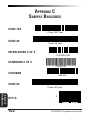
Appendix C
Sample Barcodes ....................................................... 102
R44-1027
iii
NOTES
iv
SP400RF Programming Guide
This manual contains instructions for changing interfaces, barcodes for
customizing the SP400RF scanner's operation and a listing of standard
factory settings. It is important to note that many of the features and
programming labels contained here are identical to those available for
other SP400 models. Since the SP400RF contains software enhancements and characteristics that set it apart from other models, it is recommended that this guide be used as the sole source of programming labels
and information (except for other SP400RF product-specific publications).
The organization of this manual is intended to support a variety of users
while making it quick and easy to find the information you need. Look at
the descriptions that follow to find where to go from here.
I NEED TO UNDERSTAND THE BASICS
If you do not regularly use barcode labels to configure (program) scanners, it will be very helpful to read the introductory portions of this
manual prior to beginning your programming session. In addition to the
information that follows, information of specific interest to you is titled:
—
—
—
—
—
—
—
—
—
—
Integrating Peripherals with Host Systems
Changing Interfaces
Customizing Your Scanner Operation
Programming Overview
What is Programming Mode?
How to Program Using Barcodes
The Programming Session
Scanner Response When in Programming Mode
If You Make A Mistake
Where to Go From Here
INTEGRATING PERIPHERALS WITH HOST SYSTEMS
It is important that you understand that the scanner must contain software
that supports a specific interface in order to use that interface.
Next, turn to Appendix A, Standard Factory Settings, which contains a
complete factory default configuration listing. Assuming that your scanner
is configured using the standard factory settings, use this list to identify
any changes or additions you need to make.
Then, locate the programming labels you need and change the necessary
settings. Once you have completed these steps, you can begin scanning.
R44-1027
1
GENERAL
INFORMATION
INTRODUCTION
GENERAL
INFORMATION
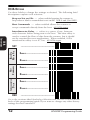
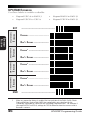
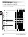
CHANGING INTERFACES
The scanner is configured at the factory to support one of two interface
groups listed in Table 1 below. Changing the current interface is simply a
matter of selecting the desired interface from your scanner's group, and
enabling the new interface using the programming labels contained in this guide.
Table 1. SP400RF Interface Groups
RS-232 • IBM • OCIA Group
RS-232
SNI RS-232
IBM 468x/9x Port 5B
IBM 468x/9x Port 9x
IBM 4682/92 Port E
PSC1 OCIA
NCR OCIA Eight Bit
NCR OCIA Nine Bit
SNI OCIA
RS-232 • Wand Emulation • Keyboard Wedge Group
RS-232
SNI RS-232
Wand Emulation
Type A — PC/XT w/foreign keyboard
Type B — AT, PS/2 25-286, 30-286, 50, 50Z, 60, 70, 80, 90 & 95
w/foreign keyboard
Type C — PS/2 25 and 30 w/foreign keyboard
Type D — PC/XT w/US keyboard
Type E — AT, PS/2 25-286, 30-286, 50, 50Z, 60, 70, 80, 90 & 95
w/US keyboard
Type F — PS/2 25 and 30 w/US keyboard
STI keyboard wedge
NOTE
If you attempt to select an interface that is
not supported by your scanner, or if the
scanner's interface hardware malfunctions,
all three LEDs will flash five times and the
scanner will automatically reset to the standard RS-232 interface. The scanner will otherwise be returned to normal function.
Once you have enabled the new interface with the appropriate label, the
new interface becomes the default interface that is active whenever power
is applied to the scanner.
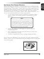
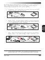
The following steps describe the interface change procedure.
2
1.
Turn to the appropriate page in this manual and scan the
desired interface enable programming label. This will enable
the software for the new interface and disable the 'old'
interface software.
2.
Scan a barcode to verify that the scanner communicates
correctly with the host system. Some sample barcodes are
provided on the last pages of this manual. If any changes to
the scanner's factory settings are needed, use the instructions
titled, Customizing Your Scanner Operation.
1
Formerly titled: "Spectra-Physics OCIA" or "S-P OCIA".
SP400RF Programming Guide
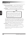
When enabling a new interface, it may be necessary to modify the standard factory settings to match your specific host system's communication
and symbology requirements. Check with your system administrator to
identify your host system's specific interface requirements to ensure that
they match the new interface you have selected. Also, the scanner's
operational features (e.g. speaker volume, radio channel frequency, etc.)
can be customized to match your unique requirements.
1.
Use the labels in this manual to modify the standard configuration to match your specific interface requirements or user
preference.
NOTE
Ensure that your planned modifications are
compatible with the current interface. For
example, baud rate selections are only valid in
the RS-232 interface. The scanner will read
and seem to accept programming labels for
features invalid to the current interface, however the feature will not be modified.
2.
Enable any additional symbologies as required and exit
Programming Mode.
3.
Scan a regular barcode label and verify that the scanner and
host communicate correctly.
4.
You have completed the factory settings change procedure.
If you experience difficulties, have questions or require additional information, contact your local distributor using the listings located on the back
cover of this guide.
R44-1027
3
GENERAL
INFORMATION
CUSTOMIZING YOUR SCANNER OPERATION
GENERAL
INFORMATION
PROGRAMMING OVERVIEW
This section describes how to set the scanner's programmable features.
These features can be configured using the barcode labels contained in
this manual or by using commands sent from the host. Refer to Appendix
B, Additional Information, for host programming details. If you program
the scanner using these barcodes, the scanner stores the changes until
reprogrammed. Whenever you use these labels to change programmable
features, you are changing these features for the active interface only.
WHAT IS PROGRAMMING MODE?
To change the scanner's programmed settings, it is necessary to place the
scanner in Programming Mode using the special “set” label. This ensures
that the scanner only recognizes the special programming labels contained
in this programming guide.
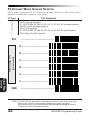
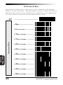
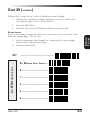
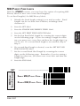
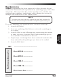
HOW TO PROGRAM USING BARCODES
The following pages contain special barcode labels that are used to
change or enable the scanner's programmable options. All programming
sessions follow this order, unless otherwise instructed:
NOTE
Programming should be performed with the
base station in near proximity to ensure optimal communication and sllow the user to
monitor the base station’s LED indicators.
4
1.
Scan the SET label at the top of the page. The scanner will
emit two beeps indicating it has read the label, and the base
station’s red LED will begin flashing. As long as the lamp is
flashing, the scanner will only recognize and decode programming labels.
2.
Scan the feature label(s) for the programmable options
you wish to enable. The scanner will emit two beeps each
time you scan a valid label. (Note that not all features are
available for all interfaces.) The first beep indicates that the
scanner has read the label, the second announces base station
acknowledgement of the label.
3.
Scan the END label at the bottom of the page to complete
the programming session and exit Programming Mode.
SP400RF Programming Guide
It is possible to program multiple features during a single programming
session (a programming session is defined as the period of time between
scanning the “set” label and scanning the “end” label). However, it is
recommended that sessions be limited to one feature, as it can be difficult
to discover where an error has been made, should you make a mistake in
the programming sequence. Additionally, it can be confusing to determine which features may or may not have been successfully set following
a failed session.
The scanner will not exit Programming Mode unless the “end” label is
scanned. Disconnecting power during Programming Mode, before
scanning the “end” label, will cause the scanner to forget any programming labels scanned during the current programming session and will
cause the scanner to return to its previous settings.
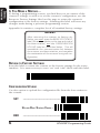
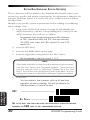
SCANNER RESPONSE WHEN IN PROGRAMMING MODE
Visual verification that the SP400RF is in Programming Mode is provided
by the red LED located on the base station, which will steadily flash until
Programming Mode is exited. While in Programming Mode, the scanner
will not decode regular barcode labels and will only enable features
supported by the currently active interface. Maintaining a good record of
all changes made will help ensure that you know if the standard factory
settings have been changed.
Scanning regular barcode labels — the scanner will reject the
label, sounding first a “good read” beep, followed by a low
“bad” beep.
Scanning a valid programming label —
a.
If the feature is supported by the active interface, the
scanner will sound two “good read” beeps.
b. If incomplete or incorrect programming has been entered
when the END label is scanned, the rejection tone will be
sounded (a “good read” beep, followed by a low “bad”
beep) regardless of whether the labels scanned were
valid programming labels. For example, if the END label
is scanned immediately following the SET label, the lack
of programming content will result in a rejection tone.
R44-1027
5
GENERAL
INFORMATION
THE PROGRAMMING SESSION
GENERAL
INFORMATION
IF YOU MAKE A MISTAKE...
If, during a programming session, you find that you are unsure of the
scanner's settings or wish to re-set the scanner's configuration, use the
Return to Factory Settings label on this page to return the scanner's
configuration to the factory settings. Scanning this label will reset any
changes made during a previous programming session.
Appendix A contains a complete list of all standard factory settings.
WARNING
After returning the scanner to factory defaults, you must scan the BASE STATION I.D.
label (located on labels on the top and side of
the base station) and the CONFIGURATION
UPLOAD label as described below. This will
reestablish the communication link between
the scanner and base station, and complete
the restoration of the scanner's original configuration.
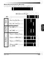
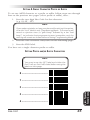
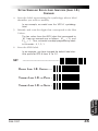
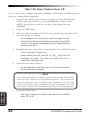
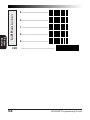
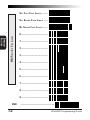
RETURN TO FACTORY SETTINGS
Scan this label to return the scanner to the factory settings for the active
interface. It is unneccessary to scan “set” and “end” labels with this label.
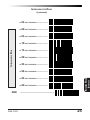
CONFIGURATION UPLOAD
Use this option to upload the configuration file from the base station to
the scanner.
SET
------------------------------------UPLOAD BASE STATION CONFIG -
END
6
------------------------------------SP400RF Programming Guide
GENERAL
INFORMATION
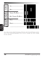
WHERE TO GO FROM HERE
Programming is easy and straightforward if you follow these steps:
1.
Turn to Appendix A and review the factory settings for the
interface you will be using.
2.
Scan the interface enable barcode label if you are changing
interfaces.
3.
Scan any feature labels that are unique to the interface you
are currently programming. These interface specific programming labels immediately follow each interface selection label.
5.
Turn to the Symbology section if you are going to change any
barcode symbologies or modify any symbology related
features.
6.
Turn to the General Features section of this guide if you wish
to change or modify any of the scanner's other features.
Once the necessary changes have been made, and you have scanned the
“end” label, you are ready to scan.
R44-1027
7
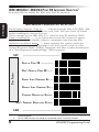
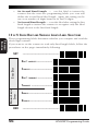
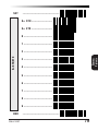
IBM 4683/84 • 4693/94 PORT 5B INTERFACE SELECTION1
Scan this label to enable the IBM 468x Port 5B interface1.
Data Format: Send As Code 39 — converts barcode data (UPC/EAN, addons, Code 93, Codabar, MSI/Plessey and Code 128) into Code 39 format
before sending the data to the host.
These settings are for IBM 4683/84 • 4693/94 Port 5B interface ONLY.
Limit Command Set — is an option that causes the scanner to ignore
'enable scanner' and 'disable scanner' commands sent from the host.
Transmit Unsolicited Status2 — when enabled, this option causes the
scanner to transmit a status message to the host upon receipt of a "Set
Normal Response Mode" (SNRM) command, and after scanner transmission
of a "Non Sequenced Acknowledge" (NSA) response.
SET
------------------------------------SEND
AS
CODE 39 ------------
DON' T SEND AS CODE 39 -----DATA FORMAT
IBM INTERFACES
IBM 4683/84 • 4693/94 PORT 5B SETTINGS
ENABLE LIMIT COMMAND SET --DISABLE LIMIT COMMAND SET -TRANSMIT UNSOLICITED STATUS DON' T TRANSMIT UNSOLICITED STATUS
END
1
2
8
-------------------------------------
Scanners manufactured prior to April 30, 1997 do not have IBM interfaces as a
selectable option.
For this IBM interface, the setting for Unsolicited Status is normally Enabled.
SP400RF Programming Guide
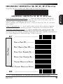
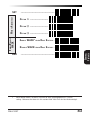
IBM 4683/84 • 4693/94 PORT 9A, 9B, 9C, 9E I/F SELECTION
Scan this label to enable the IBM 468x/9x Port 9x interface.
IBM INTERFACES
IBM 4683/84 • 4693/94 PORT 9A, 9B, 9C, 9E SETTINGS
Data Format: Send As Code 39 — converts barcode data (UPC/EAN,
add-ons, Code 93, Codabar, MSI/Plessey and Code 128) into Code 39
format before sending the data to the host.
These settings are for IBM 4683/84 • 4693/94 Port 9A, 9B, 9C, 9E interface ONLY.
Limit Command Set — is an option that causes the scanner to ignore
'enable scanner' and 'disable scanner' commands sent from the host.
Transmit Unsolicited Status1 — when enabled, this option causes the
scanner to transmit a status message to the host upon receipt of a "Set
Normal Response Mode" (SNRM) command, and after scanner transmission
of a "Non Sequenced Acknowledge" (NSA) response.
SET
------------------------------------SEND AS CODE 39 ------------
DATA FORMAT
DON'T SEND
AS
CODE 39------
ENABLE LIMIT COMMAND SET --DISABLE LIMIT COMMAND SET -TRANSMIT U NSOLICITED STATUS DON 'T TRANSMIT UNSOLICITED STATUS
END
1
-------------------------------------
For this IBM interface, the setting for Unsolicited Status is normally Disabled.
R44-1027
9
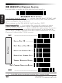
IBM 4682/92 PORT E INTERFACE SELECTION
Scan this label to enable the IBM 468x/9x Port E interface.
Limit Command Set — is an option that causes the scanner to ignore
'enable scanner' and 'disable scanner' commands sent from the host.
Transmit Unsolicited Status1 — when enabled, this option causes the scanner
to transmit a status message to the host upon receipt of a "Set Normal Response Mode" (SNRM) command, and after scanner transmission of a "Non
Sequenced Acknowledge" (NSA) response.
SET
------------------------------------SEND
AS
CODE 39 ------------
DON'T SEND AS CODE 39 -----DATA FORMAT
IBM INTERFACES
IBM 4682/92 PORT E SETTINGS
Data Format: Send As Code 39 — converts barcode data (UPC/EAN, addons, Code 93, Codabar, MSI/Plessey and Code 128) into Code 39 format
before sending the data to the host.
These settings are for IBM 4682/92 Port E interface ONLY.
ENABLE LIMIT COMMAND SET --DISABLE LIMIT COMMAND SET -TRANSMIT UNSOLICITED STATUS DON'T TRANSMIT UNSOLICITED STATUS
END
1
10
-------------------------------------
For this IBM interface, the setting for Unsolicited Status is normally Disabled.
SP400RF Programming Guide
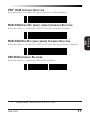
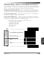
PSC1 OCIA INTERFACE SELECTION
Scan this label to enable the Spectra-Physics OCIA interface.
NCR OCIA EIGHT BIT (SHORT FORMAT) INTERFACE SELECTION
NCR OCIA NINE BIT (LONG FORMAT) INTERFACE SELECTION
Scan this label to enable the NCR OCIA Nine Bit (long format) interface.
SNI OCIA INTERFACE SELECTION
Scan this label to enable the SNI OCIA interface.
1
Formerly labeled: Spectra-Physics OCIA, or S-P OCIA.
R44-1027
11
OCIA
INTERFACES
Scan this label to enable the NCR OCIA (short format) interface.
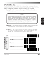
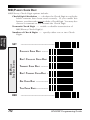
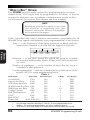
OCIA OPTIONS
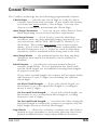
Use these labels to change the settings as desired. The following brief
descriptions explain each selection.
Beep on Not on File — when enabled requires the scanner to
beep when a label is scanned that is not on file. NCR 8 and 9 bit ONLY.
Host Commands — when enabled allows the scanner to
accept commands directly from the host. All OCIA types.
BEEP O N
NOT ON FILE
------------------------------------ENABLE ------------------------
HOST
COMMANDS
SET
ENABLE ------------------------
INTERCHARACTER
DELAY
OCIA
INTERFACES
Intercharacter Delay — refers to a pause, if any, between
each character before being sent to the host. This time delay is
used to control the flow of data from the scanner, but it should
not be required for most applications. When enabled, OCIA
intercharacter delay is set at 70µs. All OCIA types.
ENABLE ------------------------
END
DISABLE -----------------------
DISABLE -----------------------
DISABLE -----------------------------------------------------------
Go to the sections titled Symbology Selection and General Features in the
back of this programming guide if you want to change any other factory
settings for these interfaces.
12
SP400RF Programming Guide
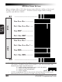
WAND EMULATION INTERFACE SELECTION
Scan this label to enable the Wand Emulation interface.
WAND EMULATION SETTINGS
POLARITY
SET
------------------------------------SPACE LOW, BAR HIGH --------
WAND EMULATION
INTERFACE
SIGNAL SPEED
SPACE HIGH, BAR LOW -------LOW (660 µS) --------------HIGH (330 µS) --------------
DATA FORMAT
TRANSMIT IN N ORMAL FORMAT -TRANSMIT IN C39 F ORMAT ----TRANSMIT IN C128 FORMAT --TRANSMIT IN C39 ------------FULL ASCII
R44-1027
13
IDLE STATE
A N OISE
TRANSMIT C128 TPRANSMIT
ATTERN B EFORE
FUNCTION CHAR' S LABEL TRANSMISSION
WAND EMULATION
INTERFACE
END
LOW -------------------------HIGH -------------------------TRANSMIT PRE-NOISE ---------DON'T TRANSMIT PRE-NOISE --ENABLE -----------------------DISABLE -----------------------------------------------------------
Go to the sections titled Symbology Selection and General Features in the
back of this programming guide if you want to change any other settings
for this interface.
14
SP400RF Programming Guide
RS-232 INTERFACE SELECTION
Scan this label to enable the RS-232 interface.
SNI RS-232 INTERFACE SELECTION
Scan this label to enable the SNI RS-232 interface.
Turn to the following pages to set the RS-232 communication parameters.
Communication Parameter
Page #
Baud Rate ------------------------------------------------------------------ 16
INTERFACE
RS-232
Data Bits ------------------------------------------------------------------- 17
Parity ------------------------------------------------------------------------ 17
Stop Bit(s) ----------------------------------------------------------------- 17
Hardware Handshaking (CTS/RTS) --------------------------------- 18
Software Handshaking (Xon/Xoff) ---------------------------------- 19
Intercharacter Delay ---------------------------------------------------- 20
Go to the sections titled Symbology Selection and General Features in the
back of this programming guide if you want to change any other factory
settings for this interface.
R44-1027
15
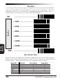
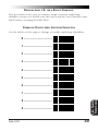
BAUD RATE
Use the barcodes on this page to select the communications Baud Rate.
Only one Baud Rate selection may be active at any one time. The last
Baud Rate label you scan during a programming session will be the
setting that is stored when you scan the END label.
SET
-----------------------------------= 1200 ----------------------
BAUD RATE
= 2400 ---------------------= 4800 ---------------------= 9600 ---------------------= 19200 --------------------
INTERFACE
RS-232
= 38400 -------------------END
------------------------------------DATA FORMAT TABLE
There are many possible data format configurations for an RS-232 interface.
Check your host system manual to find out your system's communications
requirements. This table shows the acceptable format options.
Data Bits
Seven
Seven
Seven
Eight
Eight
Eight
16
Start Bit
1
1
1
1
1
1
Parity Bit(s)
0
1
1
0
0
1
Stop Bit(s)
2
1
2
1
2
1
SP400RF Programming Guide
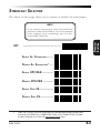
DATA FORMAT SETTINGS
The barcodes on this page can be used to select the data format configuration needed to communicate with your system.
SET
------------------------------------NONE -------------------------
PARITY
EVEN -------------------------ODD -------------------------M ARK -------------------------
ONE --------------------------
INTERFACE
RS-232
STOP BITS
S PACE ------------------------
DATA BITS
TWO --------------------------
END
R44-1027
SEVEN BITS ------------------EIGHT BITS --------------------------------------------------------
17
HANDSHAKING
Review your system documentation to identify handshaking requirements,
and use these labels to change the settings if required. The following brief
descriptions explain each selection.
HARDWARE CONTROL
CTS/RTS Flow Control — is hardware handshaking. The
scanner activates the RTS (Ready to Send) line when it is ready to
send data to the host. The scanner waits for an active Clear to
Send (CTS) signal from the host before transmitting data. If
hardware control is disabled, CTS/RTS communication will not
take place. If the host deactivates the CTS line during data transmission, the host will receive additional characters for no more
than 2msec1.
INTERFACE
RS-232
CTS Scan Control — is also a hardware control. When scan
control is enabled, label transmission is disabled until CTS is
asserted and de-asserted.
1
18
Varies slightly depending upon baud rate selected.
SP400RF Programming Guide
SOFTWARE CONTROL
XON/XOFF — this is software handshaking that allows the host to
control data transmission. If the host sends an XOFF command to
the scanner, the scanner will not send the barcode data until it
receives an XON command from the host. If the host sends the
XOFF command during data transmission, the host will receive no
more than two additional characters.
------------------------------------DISABLE HARDWARE CONTROL --
E NABLE CTS/RTS FLOW CONTROL -
END
R44-1027
ENABLE CTS SCAN CONTROL -E NABLE XON/ XOFF -----------INTERFACE
RS-232
XON/X OFF
HARDWARE CONTROL
SET
DISABLE XON/X OFF ------------------------------------------------
19
INTERCHARACTER DELAY
Intercharacter Delay refers to the pause, if any, between each character
before it is sent to the host. This time delay is used to control the flow of
data from the scanner, but it should not be required for most applications.
Use these labels to select the desired Intercharacter Delay.
SET
------------------------------------= NONE ----------------------= 10 MILLISECONDS ------------
INTERFACE
RS-232
INTERCHARACTER DELAY
= 20 MILLISECONDS -----------= 30 MILLISECONDS -----------= 40 MILLISECONDS -----------= 50 MILLISECONDS -----------= 60 MILLISECONDS -----------= 70 MILLISECONDS -----------= 80 MILLISECONDS ------------
20
SP400RF Programming Guide
INTERCHARACTER
DELAY
INTERCHARACTER DELAY
(continued)
MILLISECONDS
= 100
------------
MILLISECONDS
----------
-------------------------------------
INTERFACE
RS-232
END
= 90
R44-1027
21
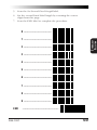
PC KEYBOARD WEDGE INTERFACE SELECTION
The scanner supports six PC Keyboard Wedge interfaces. The table below
defines the different interface selections.
I/F Type
PCs Supported
A
B
C
D
E
F
PC/XT w/foreign keyboard
AT, PS/2 25-286, 30-286, 50, 50Z, 60, 70, 80, 90 & 95 w/foreign keyboard
PS/2 25 and 30 w/foreign keyboard
PC/XT w/US keyboard
AT, PS/2 25-286, 30-286, 50, 50Z, 60, 70, 80, 90 & 95 w/US keyboard
PS/2 25 and 30 w/US keyboard
SET
------------------------------------A -----------------------------
I NTERFACE (I/F) TYPE
(SEE TABLE ABOVE)
B ----------------------------C ----------------------------D ---------------------------E ----------------------------KEYBOARD WEDGE
INTERFACE
F ----------------------------END
------------------------------------.
NOTE: If the transmission parameters are configured such that a label results in no actual
data to send, the label will be accepted, beeped, and no data transmitted.
We recommend that you disconnect power before plugging/unplugging cables to
avoid any possibility of equipment damage
22
SP400RF Programming Guide
PC KEYBOARD WEDGE – CONNECT TO A LAPTOP/NO KEYBOARD ATTACHED
If no keyboard is attached, the scanner must provide the acknowledge
signal to the PC. In this case, enable the "Laptop/No External Keyboard"
mode. If a keyboard is attached, enable "Keyboard Attached".
Laptop (integrated keyboard) — Scan the "Laptop/No External Keyboard" label below when the scanner is connected to a laptop computer
or when the scanner is operated with no external keyboard attached.
PC (external keyboard) — If you move the scanner to a standard PC,
change the setting to "Keyboard Attached".
Send Control Characters — When this feature is disabled, all ASCII
characters except NUL (00h) are transmitted. Enabling this feature limits
transmission of ASCII characters to the following:
Only ASCII characters between 20h..127h, plus…
- Carriage Return (CR=0Dh)
- BackSpace (BS=08h)
- Right Tab (HT=09h)
- Left Tab (0Bh)
- Esc (1Bh)
SEND CONTROL
CHARACTERS
CONNECT TO
LAPTOP OR PC
SET
END
R44-1027
------------------------------------LAPTOP/NO EXTERNAL KEYBOARD
KEYBOARD ATTACHED -----------
KEYBOARD WEDGE
INTERFACE
•
ENABLE -----------------------DISABLE -----------------------------------------------------------
23
INTERCHARACTER DELAY
Intercharacter Delay refers to the pause, if any, between each character
before it is sent to the host. This time delay is used to control the flow of
data from the scanner, but it should not be required for most applications.
Use these labels to select the desired Intercharacter Delay.
SET
------------------------------------= NONE -----------------------
INTERCHARACTER DELAY
=5
KEYBOARD WEDGE
INTERFACE
24
MILLISECONDS
-------------
= 10
MILLISECONDS
------------
= 15
MILLISECONDS
------------
= 20
MILLISECONDS
------------
= 25
MILLISECONDS
------------
= 30
MILLISECONDS
------------
= 35
MILLISECONDS
------------
= 40
MILLISECONDS
------------
= 45
MILLISECONDS
------------
= 50
MILLISECONDS
-----------SP400RF Programming Guide
END
R44-1027
= 55
MILLISECONDS
------------
= 60
MILLISECONDS
------------
= 65
MILLISECONDS
------------
= 70
MILLISECONDS
------------
= 75
MILLISECONDS
------------
= 80
MILLISECONDS
------------
= 85
MILLISECONDS
------------
= 90
MILLISECONDS
------------
= 95
MILLISECONDS
------------
= 99
MILLISECONDS
------------
KEYBOARD WEDGE
INTERFACE
INTERCHARACTER DELAY
INTERCHARACTER DELAY
(continued)
-------------------------------------
25
STI KEYBOARD WEDGE INTERFACE SELECTION
Scan this label to enable the STI Keyboard Wedge interface.
IMPORTANT
When enabling the STI Keyboard Wedge interface, certain parameters
must be set to ensure proper communication with the wedge. Reference
the tables below for these requirements. When all required parameters
have been set for the interface, the entire set of STI Keyboard Wedge
programmable features can be accessed using either the Master® BB+
Universal Programming Guide or the VS/HS Keyboard Wedge Programming Guide (P/N R44-1343) available through your dealer.
RS-232 I/F
Baud = 9600
Parity = Even
Stop Bits = 1
Data Bits = Seven
Hardware Control
= None
Xon/Xoff =Disable
Section of this Manual
Label Transmit
General Features
Format Config
Prefix = None
STX = None
Suffix = Carriage
ETX = None
Return (0xOD)
ACK /NAK for
Label ID = None
(except IBMXXXX. Labels = Disable
See below)
ACK /NAK for
Commands =
Disable
Label ON/OFF File
= Disable
Code 39 Symbology
Symbology = Enable
Check Digit Calc =
Don’ t Calculate
Check Digit = Don’ t
Send
Start/Stop Character =
Don’ t Send
KEYBOARD WEDGE
INTERFACE
Read One Char Label
= Disable
C39 Min Length = 1
C39 Full ASCII =
Disable
IBMXXXX STI WEDGE
The IBMXXXX STI Wedge has the exception that the Label ID must be
enabled as a Prefix using the standard default value for the symbology to
be used
26
SP400RF Programming Guide
LABEL TRANSMIT FORMAT CONFIGURATION ITEMS
(RS-232 AND KEYBOARD WEDGE INTERFACES ONLY)
If you need to send information in addition to label data, the scanner can
be configured to transmit prefixes and/or suffixes as well as symbology
specific identifier characters (Label I.D.).
PREFIX & SUFFIX
If you need to send information in addition to label data, the scanner can
be configured to transmit prefixes and/or suffixes as well as symbology
specific identifier characters. As the examples below show, none, one or
two symbology specific ASCII characters can be added to the beginning of
label in addition to multiple prefix and suffix characters.
NOTE
Using this feature requires a thorough understanding of your specific system requirements.
•
symbology specific (0 - 2) characters + label data
PP + label data
•
non-symbology specific characters (1-2) as a prefix + label
data
CpCp + label data
•
label data + non-symbology specific characters (0-2) as a
suffix
label data + CsCs
•
non-symbology specific characters (1-2) as a prefix + symbology specific characters (0-2) + label data
CpCp + PP + label data
•
symbology specific characters (0-2) + label data + nonsymbology specific characters (1-2) as a suffix
PP + label data + CsCs
•
non-symbology specific characters (1-2) as a prefix + label
data + non-symbology specific characters (1-2) as a suffix
CpCp + label data + CsCs
R44-1027
LABEL TRANSMIT
FORMAT CONFIG
The options available using this feature are:
27
•
non-symbology specific characters (1-2) as a prefix + symbology specific characters (0-2) + label data + non-symbology
specific characters (1-2) as a suffix
CpCp + PP + label data + CsCs
•
if TRANSMIT LABEL ID AS SUFFIX is enabled (see the section
titled, Setting Symbology Specific Identifiers [Label IDs]), there
can also be: non-symbology specific characters (1-2) as a
prefix + label data + symbology specific characters + nonsymbology specific characters used as suffixes.
CpCp + label data + PP + CsCs
LABEL TRANSMIT
FORMAT CONFIG
PP = symbology specific characters (Label I.D.)
CpCp = non-symbology specific ASCII characters used as prefixes
CsCs = non-symbology specific ASCII characters used as suffixes
28
SP400RF Programming Guide
SETTING NON-SYMBOLOGY SPECIFIC PREFIX(ES)
These characters will be added to the standard label format when your
host system has specific and unique requirements for information added
to the barcode label data before it is sent to the host. Identify your
specific system requirements before adding or modifying these settings,
then...
1.
Look at the ASCII chart shown on page 33 and identify the
ASCII character(s) and the corresponding Hex Code(s) for the
ASCII characters you will use as prefixes.
For example, if you are going to send two prefix characters
as 'STX' (start transmit) and 'SP' (Space). The ASCII chart
shows that 'STX' equals 02hex and 'SP' equals 20 hex.
2.
Scan the SET label.
3.
Scan the SET PREFIX label on this page.
4.
Scan the digits that correspond to the Hex Values.
For the example in step four, scan 0, 2, 2, 0.
NOTE
If you make a mistake, or lose your place while setting this option,
scan the “end” label to exit Programming Mode. The scanner will
sound a rejection tone (a “good beep” followed by a low “bad
beep”) to indicate that programming was incomplete, and the
setting will remain as it was before entering Programming Mode.
5.
Scan END.
You have added a two character prefix to all label data,
regardless of label symbology, that will be added to the
label data before it is sent to the host.
------------------------------------SET PREFIX -------------------
GO TO THE
SECOND PAGE FOLLOWING THIS AND SCAN THE APPROPRIATE CHARACTERS
BEFORE SCANNING THE
R44-1027
END
LABEL TO EXIT PROGRAMMING SESSION
.
29
LABEL TRANSMIT
FORMAT CONFIG
SET
SETTING NON-SYMBOLOGY SPECIFIC SUFFIX(ES)
These characters will be added to the standard label format when your
system has specific and unique requirements for information added to the
barcode label data before it is sent to the host. Suffix characters follow
the label data.
Identify your specific system requirements before adding or modifying
these settings, then...
1.
Look at the ASCII chart shown on page 33 and identify the
ASCII character(s) and the corresponding Hex Code(s) for the
ASCII characters you will use as suffixes.
For example, if you are going to send two suffix characters
as 'BEL' (sound host tone) and 'ETX' (end transmission).
The ASCII chart shows that 'BEL' equals 07 hex and 'ETX'
equals 03hex.
2.
Scan the SET label.
3.
Scan the Set Suffix label on this page.
4.
Scan the digits that correspond to the Hex Values.
For the example in step five, scan 0, 7, 0, 3.
NOTE
If you make a mistake, or lose your place while setting this option,
scan the “end” label to exit Programming Mode. The scanner will
sound a rejection tone (a “good beep” followed by a low “bad
beep”) to indicate that programming was incomplete, and the
setting will remain as it was before entering Programming Mode.
5.
Scan END.
You have added a two character suffix to all label data,
regardless of label symbology, that will be added to the
label data before it is sent to the host.
LABEL TRANSMIT
FORMAT CONFIG
SET
------------------------------------SET SUFFIX -------------------
GO
TO THE NEXT TWO PAGES AND SCAN THE APPROPRIATE CHARACTERS BEFORE
SCANNING THE
30
END
LABEL TO EXIT PROGRAMMING SESSION
.
SP400RF Programming Guide
SETTING A SINGLE CHARACTER PREFIX OR SUFFIX
To set one ASCII character as a prefix or suffix, follow steps one through
four on the previous two pages (select prefix or suffix), then...
1.
Scan the two digit Hex Code for that character.
(e.g. 03, 8F, ...FF)
NOTE
If you make a mistake, or lose your place while setting this option,
scan the “end” label to exit Programming Mode. The scanner will
sound a rejection tone (a “good beep” followed by a low “bad
beep”) to indicate that programming was incomplete, and the
setting will remain as it was before entering Programming Mode.
2.
Scan the One Character Only label on the following page.
3.
Scan the END label.
You have set a single character prefix or suffix.
SETTING PREFIX AND/OR SUFFIX CHARACTERS
NOTE
You must scan the SET label and either the
Set Prefix or Set Suffix label before using the
labels on this page.
0 ----------------------------1 -----------------------------
LABEL TRANSMIT
FORMAT CONFIG
2 ----------------------------3 ----------------------------4 -----------------------------
R44-1027
31
5 ----------------------------6 ----------------------------7 ----------------------------8 ----------------------------9 ----------------------------A ----------------------------B ----------------------------C ----------------------------D ---------------------------E ----------------------------F ----------------------------ONE CHARACTER ONLY --------LABEL TRANSMIT
FORMAT CONFIG
END
32
-------------------------------------
SP400RF Programming Guide
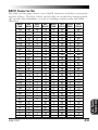
ASCII CHARACTER SET
ASCII
C HAR.
HEX
V ALUE
ASCII
C HAR.
HEX
V ALUE
ASCII
C HAR.
HEX
V ALUE
ASCII
C HAR.
HEX
V ALUE
nul
soh
stx
etx
eot
enq
ack
bel
bs
ht
lf
vt
ff
cr
so
si
dle
dc1
dc2
dc3
dc4
nak
syn
etb
can
em
sub
esc
fs
gs
rs
us
00
01
02
03
04
05
06
07
08
09
0A
0B
0C
0D
0E
0F
10
11
12
13
14
15
16
17
18
19
1A
1B
1C
1D
1E
1F
sp
!
"
#
$
%
&
'
(
)
*
+
'
.
/
0
1
2
3
4
5
6
7
8
9
:
;
<
=
>
?
20
21
22
23
24
25
26
27
28
29
2A
2B
2C
2D
2E
2F
30
31
32
33
34
35
36
37
38
39
3A
3B
3C
3D
3E
3F
@
A
B
C
D
E
F
G
H
I
J
K
L
M
N
O
P
Q
R
S
T
U
V
W
X
Y
Z
[
\
]
^
_
40
41
42
43
44
45
46
47
48
49
4A
4B
4C
4D
4E
4F
50
51
52
53
54
55
56
57
58
59
5A
5B
5C
5D
5E
5F
`
a
b
c
d
e
f
g
h
i
j
k
l
m
n
o
p
q
r
s
t
u
v
w
x
y
z
{
|
}
~
del
60
61
62
63
64
65
66
67
68
69
6A
6B
6C
6D
6E
6F
70
71
72
73
74
75
76
77
78
79
7A
7B
7C
7D
7E
7F
R44-1027
LABEL TRANSMIT
FORMAT CONFIG
The table on this page shows a set of ASCII characters and their corresponding Hex Values. The Hex Values in this table are needed for setting symbology specific label identifiers, as well as enabling custom prefix and suffix
characters.
33
SETTING SYMBOLOGY SPECIFIC LABEL IDENTIFIERS (LABEL I.D.)
Symbology-specific label identifiers comprise one or two ASCII characters
that can precede or follow barcode label data as it is transmitted to the
host. The host uses these characters as a means of distinguishing between
symbologies.
Industry standards have been established for symbology-specific label
identifiers, and are listed in the table below. Factory default identifiers are
preset to these standards for the SP400RF scanner.
UPC-A ------------------------ 'A'
UPC-E ------------------------ 'E'
EAN-8 ----------------------- 'FF'
EAN-13 ----------------------- 'F'
UPC-A (2 add-on) --------- 'A'
UPC-A (5 Add-on) --------- 'A'
UPC-A (8 Add-on) ---------- 'A'
UPC-E (2 add-on) --------- 'E'
UPC-E (5 Add-on) --------- 'E'
UPC-E (8 Add-on) ---------- 'E'
EAN-8 (2 add-on) --------- 'FF'
EAN-8 (5 Add-on) -------- 'FF'
EAN-8 (8 Add-on) ---------- 'FF'
EAN-13 (2 add-on) -------- 'F'
EAN-13 (5 Add-on) -------- 'F'
EAN-13 (8 Add-on) --------- 'F'
Code 39 ---------------------- '*'
Codabar --------------------- '%'
Interleaved.2 of 5 ----------- 'i'
Standard.2 of 5 ------------- 's'
Code 93 ---------------------- '&'
Code 128 -------------------- '#'
MSI/Plessey ---------------- '@'
TABLE 1. INDUSTRY STANDARD LABEL IDENTIFIERS (ALL ARE PREFIXES)
To set symbology-specific label identifiers:
1.
Look at the ASCII chart shown on the previous page and
identify the ASCII character(s) and the corresponding Hex
Code(s) for the ASCII characters you will use as identifiers.
You will also need to determine whether the character(s) will
need to be sent as a prefix or a suffix.
For example: You need to change the label identifier prefix
for UPC-A to 'A1'.
LABEL TRANSMIT
FORMAT CONFIG
2.
Scan the SET label below.
3.
Scan either the TRANSMIT LABEL I.D. AS PREFIX or TRANSMIT LABEL I.D. AS SUFFIX, depending on your requirements.
For our example, the 'transmit as prefix' label would be
scanned.
34
SP400RF Programming Guide
SETTING SYMBOLOGY SPECIFIC LABEL IDENTIFIERS (LABEL I.D.)
CONTINUED
4.
Scan the label representing the symbology whose label
identifier you wish to modify.
In our example, we would scan the 'UPC-A' symbology
label.
5.
Identify and scan the digits that correspond to the Hex
Values.
The hex values from the ASCII chart that correspond to
'A1' from our example are as follows: 41hex = 'A', and
31 hex = '1'. Thus, we would scandigit programming labels
in this order: 4, 1, 3, 1.
6.
Scan the END label.
In our example, you have changed the default label identifier prefix for UPC-A from 'A' to 'A1'.
SET
------------------------------------DISABLE LABEL I.D. CONTROL ----
AS
PREFIX -
TRANSMIT LABEL I.D.
AS
SUFFIX -
LABEL TRANSMIT
FORMAT CONFIG
TRANSMIT LABEL I.D.
R44-1027
35
LABEL I.D. SYMBOLOGY SELECTION
UPC-A ---------------------ADD ON
-
----
UPC-A W/5 DIGIT
ADD ON
-
----
UPC-A W/8 DIGIT
ADD ON
-
----
SET SYMBOLOGY SPECIFIC LABEL IDENTIFIER
FOR
:
UPC-A W/2 DIGIT
UPC-E ---------------------UPC-E W/2
DIGIT ADD ON
-
----
UPC-E W/5
DIGIT ADD ON
-
----
UPC-E W/8
DIGIT ADD ON
-
----
EAN-8 ---------------------EAN-8 W /2 DIGIT ADD -ON ----EAN-8 W /5 DIGIT ADD -ON -----
LABEL TRANSMIT
FORMAT CONFIG
EAN-8 W /8 DIGIT ADD -ON ----EAN-13 ---------------------
36
SP400RF Programming Guide
SET SYMBOLOGY SPECIFIC LABEL IDENTIFIER FOR:
LABEL I.D. SYMBOLOGY SELECTION
CONTINUED
EAN-13 W/2 DIGIT
ADD ON
-
---
EAN-13 W/5 DIGIT
ADD ON
-
---
EAN-13 W/8 DIGIT
ADD ON
-
---
CODE 39 --------------------CODABAR ---------------------I NTERLEAVED 2
OF
5 -----------
STANDARD 2 OF 5 ------------CODE 93 --------------------CODE 128 --------------------
LABEL TRANSMIT
FORMAT CONFIG
MSI/PLESSEY ----------------
R44-1027
37
HOW TO SET SINGLE CHARACTER LABEL I.D.
If you only want a single character identifier, follow this modified procedure for setting label identifier.
1.
Look at the ASCII chart shown on page 33 and identify the
ASCII character and the corresponding Hex Code for the
ASCII character you will use as the symbology specific
identifier.
2.
Scan the SET label.
3.
Scan the label identifier label for the symbology identifier that
you are going to change.
As an example, assume that you want to change the label
identifier for EAN-8 from the default setting FF to the ASCII
value 8. Scan the Set Symbology Specific Label Identifier
barcode for EAN-8.
5.
Identify the hex value that correspond to the ASCII character.
In this example '8' equals 38 hex.
Simply follow the hex value for '8' (38 hex) with the One
Character Only label. This tells the scanner that '8' is a
single digit label identifier.
6.
Scan the barcodes values.
For the example in step five, scan 3, 8, One Character Only
on the following two pages.
NOTE
If you make a mistake, or lose your place while setting this option,
scan the “end” label to exit Programming Mode. The scanner will
sound a rejection tone (a “good beep” followed by a low “bad
beep”) to indicate that programming was incomplete, and the
setting will remain as it was before entering Programming Mode.
7.
Scan the END label.
LABEL TRANSMIT
FORMAT CONFIG
You have changed the default label identifier for EAN-8
from 'FF' to '8'.
38
SP400RF Programming Guide
DISABLING LABEL I.D. FOR A SPECIFIC SYMBOLOGY
This procedure is the same as setting a single character symbology
identifier, except you should scan two zeros and the One Character Only
labels before scanning the END label.
SYMBOLOGY SPECIFIC LABEL IDENTIFIERS CHARACTERS
Use the labels on this page to change or modify symbology identifiers.
0 ----------------------------1 ----------------------------2 ----------------------------3 ----------------------------4 ----------------------------5 ----------------------------6 ----------------------------7 ----------------------------LABEL TRANSMIT
FORMAT CONFIG
8 ----------------------------9 -----------------------------
R44-1027
39
A ----------------------------B ----------------------------C ----------------------------D ---------------------------E ----------------------------F ----------------------------ONE CHARACTER ONLY --------END
-------------------------------------
LABEL TRANSMIT
FORMAT CONFIG
40
SP400RF Programming Guide
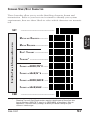
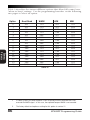
SYMBOLOGIES
The factory settings for each interface were chosen to meet the standard
industry requirements and in most cases you will not need to change the
symbology format settings. If you are unsure of your system requirements, test the scanner using the factory settings before making any
changes.
Code 93
Code 128
MSI/Plessey
INTERFACE TYPE
UPC/EAN
Code 39
Inter. 2 of 5
Std 2 of 5
Codabar
SYMBOLOGIES
SUPPORTED
IBM Port 5B
IBM Port 9B
IBM Port E
NCR OCIA (8 bit)
NCR OCIA (9 bit)
S-P OCIA
SNI OCIA
RS-232
Wand Emulation
Keyboard Wedge
R44-1027
41
SYMBOLOGY
SELECTION
Symbology selection (barcode type) determines which symbologies the
scanner will decode. The chart below shows the symbologies that are
supported by each interface. Once you have identified the symbologies
you wish to enable, turn to the following pages, enable those symbologies
and set the data format options (e.g. check digit, start/stop characters)
required by your host system for each symbology type. You must enable
the symbology format options settings that are compatible with your host
system.
SYMBOLOGY OPTIONS OVERVIEW
Enable All Symbologies — allows the scanner to auto-discriminate
between all the symbologies in this list. Use this selection only
if you must constantly read a wide variety of symbologies. Turn
to the following pages for enabling additional symbology
specific options.
Disable All Symbologies — disables all symbologies. The scanner
will only recognize the programming labels contained in this
manual while you are in Programming Mode.
SYMBOLOGY
SELECTION
Enable UPC/EAN — tells the scanner to recognize UPC-A, UPC-E,
EAN-8, and EAN-13. If you enable this symbology, additional
options for symbology expansion and reading add-ons are
available. Allows selection of expansion and add-on options.
Enable Code 39 — selects Code 39 as an active symbology. Allows
selection of Check Digit, Start/Stop and Single Digit options.
Enable Interleaved 2 of 5 — selects Interleaved 2 of 5 as an active
symbology. Allows change of Check Digit or label format (fixed
or variable length) options.
Enable Standard 2 of 5 — selects Standard 2 of 5 as an active
symbology. Allows change of Check Digit or label format (fixed
or variable length) options.
Enable Codabar — selects Codabar as an active symbology. Allows
selection of Check Digit, Start/Stop character and format, or label
format (fixed or variable length) options.
Enable Code 93 — selects Code 93 as an active symbology. The
scanner is preset to recognize all Code 93 barcodes that have
between 2 and 50 characters. Code 93 has no user selectable
options.
Enable Code 128 — selects Code 128 as an active symbology. The
scanner is preset to recognize all Code 128 barcodes that have
between 2 and 50 characters. Code 128 has no user selectable
options.
Enable MSI/Plessey — selects MSI/Plessey as an active symbology.
Allows selection of Check Digit or label format (fixed or variable
length) options.
42
SP400RF Programming Guide
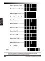
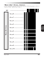
SYMBOLOGY SELECTION
The labels on this page allow you to enable or disable all symbologies.
NOTE
SET
SYMBOLOGY
SELECTION
If you enable a symbology that has additional
features that should be set, turn to the pages
that support that symbology and its programmable features.
-------------------------------------
ENABLE ALL SYMBOLOGIES -----DISABLE ALL SYMBOLOGIES 1 -------ENABLE UPC/EAN ----------DISABLE UPC/EAN ---------ENABLE CODE 39 -------------DISABLE CODE 39 -------------
1
Code 128 is always active for the purpose of reading programming barcode labels.
Scanning the DISABLE ALL SYMBOLOGIES label or the DISABLE CODE 128 label
disables decoding of all Code 128 non-programming labels.
R44-1027
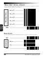
43
ENABLE INTERLEAVED 2
OF
5 ---
DISABLE INTERLEAVED 2 OF 5 ---
ENABLE STANDARD 2 OF 5 ----DISABLE STANDARD 2 OF 5 ---SYMBOLOGY
SELECTION
ENABLE CODABAR -------------DISABLE CODABAR -------------
ENABLE CODE 93 -------------DISABLE CODE 93 ------------ENABLE CODE 128 -----------DISABLE CODE 1281 ------------------ENABLE MSI/PLESSEY --------DISABLE MSI/PLESSEY --------
END
1
44
-------------------------------------
Code 128 is always active for the purpose of reading programming barcode labels.
Scanning the DISABLE ALL SYMBOLOGIES label or the DISABLE CODE 128 label
disables decoding of all Code 128 non-programming labels.
SP400RF Programming Guide
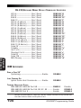
UPC/EAN OPTIONS
The information below provides a brief description of the programmable
UPC/EAN features included on the following pages.
Expand UPC-A to EAN-13 — adds a leading zero to a UPC-A
label which 'expands' the label to the EAN-13 data format.
Selecting this feature also changes the symbology ID to match
those required for EAN-13.
SYMBOLOGY
SELECTION
Expand UPC-E to UPC-A — expands UPC-E labels to UPC-A
data format. Selecting this feature also changes the symbology ID to match those required for UPC-A.
If this feature and Expand UPC-A to EAN-13 are both enabled, label data will be sent to the host in EAN-13 label
format.
Expand EAN-8 to EAN-13 — adds five zeros in front of an
EAN-8 label. Data is sent in EAN-13 data format. Selecting
this feature also changes the symbology ID to match those
required for EAN-13.
Expand UPC-E to EAN-13 — expands UPC-E labels to EAN-13
data format. Selecting this feature also changes the symbology ID to match those required for EAN-13.
UPC-A or UPC-E and EAN-8 or EAN-13 Two and Five Digit
Add-Ons
Optional — scanner will read UPC/EAN barcodes with or
without add-ons.
Required — UPC/EAN barcodes must have add-on or label
will not be read.
Disable — scanner will not recognize/read add-on portion
of UPC/EAN labels, but will read the main body of the label.
Price/Weight Check Digit — provides options for enabling
price/weight check digits. The feature includes selections for
domestic four or five digit, and European four or five digit, as
well as the option to disable the price/weight check.
R44-1027
45
UPC/EAN EXPANSION
Use these labels to enable or disable:
•
Expand UPC-A to EAN-13
•
Expand EAN-8 to EAN-13
•
Expand UPC-E to UPC-A
•
Expand UPC-E to EAN-13
E XPANSION
------------------------------------E XPAND1 ---------------------------------------
E XPANSION
E XPAND1 ----------------------
EXPANSION
DON 'T EXPAND ----------------
E XPAND1 ----------------------
DON 'T EXPAND ----------------
DON 'T EXPAND ---------------E XPAND1 ---------------------------------------
EXPANSION
UPC-E TO UPC-A
EAN-8 TO EAN-13
UPC-E TO EAN-13
SYMBOLOGY
SELECTION
UPC-A TO EAN-13
SET
DON 'T EXPAND ----------------
END
1
46
-------------------------------------
When any expansion feature is enabled, the transmission of the Prefix, Suffix, Check
Digit and Number System Digit (NSD) are controlled by your selections for the
symbology 'expanded to' rather than the symbology 'expanded from'. For example, if
you expand UPC-E to UPC-A, settings for UPC-A determine how the scanner sends a
barcode's contents.
SP400RF Programming Guide
UPC/EAN ADD-ONS
If you need to scan UPC or EAN labels that include Add-on codes, the
selections on this page set the scanner's Add-on feature. There are three
Add-on read modes available: optional, required and disabled.
Optional — the scanner will recognize UPC barcodes with or
without Add-ons.
SYMBOLOGY
SELECTION
NOTE
Due to the structure of Add-on codes, selecting the Optional
setting makes it impossible to ensure that the scanner will
always read the Add-on portion of the label. Spectra-Physics
makes no guarantee, either written or implied, that scanners
with optional Add-on decoding enabled will perform with the
speed and accuracy required for any given application.
Required — the scanner will not recognize or decode any UPC/
EAN labels that do not contain an Add-on segment.
Disabled — the scanner will not recognize or decode any Addon segment of UPC/EAN labels. The scanner will read and
decode the standard UPC/EAN portion of the label.
T WO DIGIT & FIVE D IGIT
ADD -ONS
SET
END
R44-1027
------------------------------------OPTIONAL --------------------REQUIRED --------------------DISABLED ----------------------------------------------------------
47
UPC DATA FORMAT SETTINGS
These settings affect UPC data format when RS-232, OCIA or Keyboard
Wedge is the active interface. Number System Digit (NSD) settings
operate with RS-232 ONLY.
SET
------------------------------------SEND CHECK DIGIT ------------
UPC-A
SEND NSD1 -----------------DON'T SEND NSD1 ----------SEND CHECK DIGIT2 ----------DON'T SEND CHECK DIGIT2 -----
UPC-E
SYMBOLOGY
SELECTION
DON'T SEND CHECK DIGIT -----
SEND NSD2 -----------------DON'T SEND NSD2 -----------
END
1
2
48
-------------------------------------
NSD = Number System Digit. The NSD character is the character that precedes the
UPC barcode. The NSD for regular UPC-A barcodes is a zero. Other commonly used
Number System Digits used with UPC-A are:
2 - used for random weight items such as meat and produce
3 - used for the drug and health items
0
4 - used for in-store non-food items
xxxxx xxxxx
NSD
5 - used for coupons
If UPC-E is expanded to UPC-A, the transmission of Check Digit (CD) and NSD will be
determined by the UPC-A settings on this page, not by these settings.
SP400RF Programming Guide
EAN DATA FORMAT SETTINGS
These settings affect EAN data format when RS-232 or OCIA is the active
interface.
EAN-13
END
R44-1027
------------------------------------SEND CHECK DIGIT -----------SYMBOLOGY
SELECTION
EAN-8
SET
DON'T SEND CHECK DIGIT ----SEND CHECK DIGIT -----------DON'T SEND CHECK DIGIT -----------------------------------------
49
PRICE/WEIGHT CHECK DIGIT
The price/weight check digit selections allow you to specify whether the
scanner should calculate an extra check digit based on a four or five-digit
price/weight block and compare it with the price/weight check digit
contained in the barcode. If the calculated check digit does not match the
value of the check digit contained in the barcode, the label will be
rejected as invalid. Select domestic four or five digit, European four or
five digit, or disable the price/weight check.
SET
-------------------------------------
PRICE/WEIGHT CHECK DIGIT
SYMBOLOGY
SELECTION
DISABLE PRICE/WEIGHT CHECK ENABLE 4 DIGIT CHECK -------ENABLE 5 DIGIT CHECK -------ENABLE EURO 4 DIGIT CHECK -ENABLE EURO 5 DIGIT CHECK -END
50
-------------------------------------
SP400RF Programming Guide
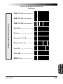
CODE 39 OPTIONS
The Code 39 symbology has the following programmable features:
You may also choose to transmit or not transmit the Check
Digit independent of whether the Check Digit is calculated by
the scanner. If you choose to Transmit Check Digit, but not
calculate, the scanner sends the Check Digit encoded in the
barcode without verifying its accuracy. If you choose Don't
Transmit Check Digit, the scanner will remove the Check
Digit's contents before sending the barcode data to the host.
Start/Stop Characters — you can choose either Send or Don't
Send depending on your host's interface requirement.
Code 39 Full ASCII — enable or disable Full ASCII Mode.
Code 39 Minimum Label Length — set the minimum label
length required for Code 39 labels (not including the check
character). This feature is provided to ignore small label
segments, reducing the possibility that a portion of a good
label is incorrectly seen as an entire label.
R44-1027
51
SYMBOLOGY
SELECTION
Check Digit — calculate the Check Digit to verify that the
Check Digit contained in the barcode label is correct. If you
enable this feature, your barcodes must contain a Check Digit.
CODE 39 (CONTINUED)
Use these labels to change the Code 39 programmable features.
SET
-------------------------------------
COMPUTE ---------------------DON'T TRANSMIT --------------
START/S TOP
TRANSMIT ---------------------
CODE 39 F ULL
ASCII
SYMBOLOGY
SELECTION
CHECK DIGIT
DON'T COMPUTE ---------------
END
52
DON'T
TRANSMIT
---------------
TRANSMIT --------------------ENABLE -----------------------DISABLE -----------------------------------------------------------
SP400RF Programming Guide
CODE 39 (CONTINUED)
1.
Identify the minimum length setting you want to make. The
selectable range is 00 to 48 characters.
2.
Scan the SET label.
3.
Scan the Set Code 39 Minimum Label Length barcode.
SETTING LENGTHS
If you are setting a length less than ten, you must scan a zero first and
then the length digit ( 04, 06, 08).
4.
Set the minimum label length by scanning the correct digits
from below and the next page.
5.
Scan the END label.
SET
-------------------------------------
CODE 39 MINIMUM LABEL LENGTH
SET MINIMUM LABEL LENGTH --0 ----------------------------1 ----------------------------2 ----------------------------3 ----------------------------4 -----------------------------
R44-1027
53
SYMBOLOGY
SELECTION
Follow these steps to set Code 39 Minimum Label Length:
SYMBOLOGY
SELECTION
CODE 39 MINIMUM LABEL LENGTH
5 -----------------------------
END
54
6 ----------------------------7 ----------------------------8 ----------------------------9 -----------------------------------------------------------------
SP400RF Programming Guide
INTERLEAVED 2 OF 5
The Interleaved 2 of 5 symbology has the following programmable
features:
You may also choose to transmit or not transmit the Check
Digit independent of whether the Check Digit is calculated by
the scanner. If you choose to Transmit Check Digit, but not
calculate, the scanner sends the Check Digit encoded in the
barcode without verifying its accuracy. If you choose Don't
Transmit Check Digit, the scanner will remove the Check
Digit's contents before sending the barcode data to the host.
Label Format — provides the selection between fixed or
variable length labels. If your application has labels with
specific fixed lengths, we recommend selecting fixed lengths
to improve read rate and avoid short reads.
You can select any valid number of digits for reading specific
length labels only. Read the following details for specific
Interleaved 2 of 5 limits.
INTERLEAVED 2 OF 5 LABEL LENGTHS
Interleaved 2 of 5 Minimum Label Length — set the minimum label length required for I 2/5 labels (not including the
check character). This feature is provided to ignore small
label segments, reducing the possibility that a portion of a
good label is incorrectly seen as an entire label.
Variable Length — If you select variable length, the scanner
will recognize labels with an even number of digits between
04 and 50 digits.
Fixed Length — If you select fixed length, there are three labels
for programming your scanner to read either one or two
fixed lengths. The labels are:
•
Set First Fixed Length — use this label to instruct the scanner
that the next two programming labels you scan will define the
first fixed label length. This setting can be any even number of
digits between 04 and 50 digits.
R44-1027
55
SYMBOLOGY
SELECTION
Check Digit — calculate the Check Digit to verify that the
Check Digit contained in the barcode label is correct. If you
enable this feature, your barcodes must contain a Check
Digit.
•
Set Second Fixed Length — use this label to instruct the
scanner that the next two programming labels you scan will
define the second fixed label length. Again, this setting can be
any even number of digits between 04 and 50 digits.
•
No Second Fixed Length — scan this label after setting the first
fixed length to instruct the scanner to recognize only the label
length chosen as the first fixed length.
I 2 OF 5 CHECK DIGIT AND VARIABLE LENGTH LABEL SELECTIONS
If you want to set the scanner to read only fixed length labels, follow the
procedures on the pages immediately following.
SET
-------------------------------------
CHECK DIGIT
DON'T
COMPUTE
----------------
COMPUTE ---------------------DON'T
TRANSMIT
---------------
TRANSMIT --------------------VARIABLE LENGTH
L ABELS
SYMBOLOGY
SELECTION
These programming labels determine whether you compute and send the
check digit contents.
END
56
ENABLE -----------------------DISABLE -----------------------------------------------------------
SP400RF Programming Guide
SETTING INTERLEAVED 2 OF 5 FIXED AND MINIMUN LABEL LENGTHS
All interfaces that are shipped with the standard factory configuration are
set to read variable length labels. If you switch from variable to fixed
length labels, the default fixed label lengths are 14 digits and 8 digits.
Follow the steps below to change these defaults. All fixed length settings
for Interleaved 2 of 5 must be an even number.
2.
Scan the SET label.
3.
Scan the Enable First Fixed barcode.
SETTING FIXED LENGTHS
If you are setting a length less than ten, you must scan a zero first and
then the length digit ( 04, 06, 08).
4.
Set the first fixed label length by scanning the correct digits
from the next two pages.
If you need to set a second fixed length, continue with step
five. If you do not need to set a second fixed length scan the
No 2nd Fixed Length on this page and skip to step seven.
5.
Scan the Set Second Fixed label.
6.
Set the second fixed label length by scanning the correct
digits from this page.
7.
Scan the END label to complete the procedure.
SETTING MINIMUM LABEL LENGTH
1. Identify the minimum length setting you want to make. The
selectable range is 00 to 48 characters.
2.
Scan the SET label.
3.
Scan the SET MINIMUM LABEL LENGTH barcode.
If you are setting a length less than ten, you must scan a zero first and
then the length digit ( 04, 05, 09).
4.
Set the minimum label length by scanning the correct digits
from the next two pages.
5.
Scan the END label.
R44-1027
57
SYMBOLOGY
SELECTION
SET FIXED
1. Identify the fixed length settings you want to make.
SET
------------------------------------SET FIRST FIXED LENGTH -----SET SECOND FIXED LENGTH ----
SET MINIMUM LABEL LENGTH --0 ----------------------------1 ----------------------------2 -----------------------------
OF
I NTERLEAVED 2
SYMBOLOGY
SELECTION
5 FIXED AND MINIMUM LABEL LENGTHS
NO SECOND FIXED LENGTH -----
3 ----------------------------4 ----------------------------5 ----------------------------6 ----------------------------7 -----------------------------
58
SP400RF Programming Guide
END
R44-1027
OF
5 FIXED AND MINIMUM LABEL LENGTHS—CONTINUED
8 ----------------------------9 -----------------------------
SYMBOLOGY
SELECTION
INTERLEAVED 2 OF 5 FIXED
AND M INIMUM LABEL L ENGTHS
SETTING INTERLEAVED 2
-------------------------------------
59
STANDARD 2 OF 5
The Standard 2 of 5 symbology has the following programmable features:
Normal or IATA Selection — offers a choice between using
"normal" format or IATA (International Airline Transport
Association) format within the Standard 2 of 5 symbology.
IATA is used for international tickets and boarding passes.
Check Digit — calculate the Check Digit to verify that the
Check Digit contained in the barcode label is correct. If you
enable this feature, your barcodes must contain a Check Digit.
SYMBOLOGY
SELECTION
NOTE
If you are using the IATA format, ONLY labels
with 15 characters will actually have their
Check Digit calculated per IATA standards
(recommended Practice 1720a, attachment
D, current 6/95). Labels with lengths other
than 15 characters will be passed without any
check digit calculation.
You may also choose to transmit or not transmit the Check
Digit independent of whether the Check Digit is calculated by
the scanner. If you choose to Transmit Check Digit, but not
calculate, the scanner sends the Check Digit encoded in the
barcode without verifying its accuracy. If you choose Don't
Transmit Check Digit, the scanner will remove the Check
Digit's contents before sending the barcode data to the host.
Label Format — provides the selection between fixed or
variable length labels. If your application has labels with
specific fixed lengths, we recommend selecting fixed lengths
to improve read rate and avoid short reads.
You can select any valid number of digits for reading specific
length labels only. Read the following details for specific
Standard 2 of 5 limits.
60
SP400RF Programming Guide
STANDARD 2 OF 5 LABEL LENGTHS
Standard 2 of 5 Minimum Label Length — set the minimum
label length required for I 2/5 labels (not including the check
character). This feature is provided to ignore small label
segments, reducing the possibility that a portion of a good
label is incorrectly seen as an entire label.
Fixed Length — If you select fixed length, there are three labels
for programming your scanner to read either one or two fixed
lengths. The labels are:
•
Set First Fixed Length — use this label to instruct the scanner
that the next two programming labels you scan will define the
first fixed label length. This setting can be any number of digits
between 01 and 50 digits.
•
Set Second Fixed Length — use this label to instruct the
scanner that the next two programming labels you scan will
define the second fixed label length. Again, this setting can be
any number of digits between 01 and 50 digits.
•
No Second Fixed Length — scan this label after setting the first
fixed length to instruct the scanner to recognize only the label
length chosen as the first fixed length.
NORMAL OR IATA SELECTION
Use these labels to select either normal, or IATA (International Airline
Transport Association) format.
SET
------------------------------------NORMAL STANDARD 2 OF 5 ---IATA STANDARD 2
END
R44-1027
OF
5 ------
-------------------------------------
61
SYMBOLOGY
SELECTION
Variable Length — If you select variable length, the scanner will
recognize labels with an even number of digits between 01
and 50 digits.
STD 2 OF 5 CHECK DIGIT AND VARIABLE LENGTH LABEL SELECTIONS
These programming labels determine whether you compute and send the
check digit contents.
If you want to set the scanner to read only fixed length labels, follow the
procedures on the pages immediately following.
SET
------------------------------------COMPUTE
----------------
COMPUTE ---------------------DON 'T
TRANSMIT
---------------
TRANSMIT --------------------VARIABLE LENGTH
L ABELS
SYMBOLOGY
SELECTION
CHECK DIGIT
DON 'T
ENABLE -----------------------DISABLE -----------------------
END
-------------------------------------
SETTING STANDARD 2 OF 5 FIXED AND MINIMUN LABEL LENGTHS
All interfaces that are shipped with the standard factory configuration are
set to read variable length labels. If you switch from variable to fixed
length labels, the default fixed label lengths are 14 digits and 8 digits.
Follow the steps below to change these defaults.
62
SP400RF Programming Guide
SET FIXED
1. Identify the fixed length settings you want to make.
2.
Scan the SET label.
3.
Scan the Enable First Fixed barcode.
SETTING FIXED LENGTHS
If you are setting a length less than ten, you must scan a zero first and
then the length digit ( 01, 08, 09).
4.
Set the first fixed label length by scanning the correct digits
from the next two pages. (Selectable range is 01 to 50 digits.)
5.
Scan the Set Second Fixed label.
6.
Set the second fixed label length by scanning the correct
digits from this page.
7.
Scan the END label to complete the procedure.
SYMBOLOGY
SELECTION
If you need to set a second fixed length (selectable range is
00 to 50 digits.), continue with step five. If you do not need
to set a second fixed length scan the No 2nd Fixed Length on
this page and skip to step seven.
SETTING MINIMUM LABEL LENGTH
1. Identify the minimum length setting you want to make. The
selectable range is 01 to 50 characters.
2.
Scan the SET label.
3.
Scan the SET MINIMUM LABEL LENGTH barcode.
If you are setting a length less than ten, you must scan a zero first and
then the length digit ( 04, 05, 09).
4.
Set the minimum label length by scanning the correct digits
from the next two pages.
5.
Scan the END label.
SET
------------------------------------SET FIRST FIXED LENGTH ------
R44-1027
63
SET SECOND FIXED LENGTH ---NO SECOND FIXED LENGTH ----SET MINIMUM LABEL LENGTH ---
1 ----------------------------2 ----------------------------3 ----------------------------4 -----------------------------
OF
STANDARD 2
SYMBOLOGY
SELECTION
5 FIXED AND MINIMUM LABEL LENGTHS
0 -----------------------------
5 ----------------------------6 ----------------------------7 ----------------------------8 ----------------------------9 -----------------------------
END
64
------------------------------------SP400RF Programming Guide
CODABAR OPTIONS
The Codabar symbology has the following programmable features:
Check Digit — calculate the Check Digit to verify the labels
contents have been read correctly. If you enable this feature,
your barcodes must include a Check Digit. You may also
choose to transmit or not transmit the Check Digit.
Start/Stop Characters — you can choose either Send or Don't
Send depending on your host's interface requirement.
SYMBOLOGY
SELECTION
Start/Stop Format — if you need to send the Start/Stop
characters, there are four standard format options that you
can select from; ABCD/TN*E, ABCD/ABCD, abcd/tn*e, or
abcd/abcd. This setting must match your system requirements. If you select one of these options, it determines how
the ASCII characters A, B, C, D that are used for Start/Stop
characters, will be translated before being sent to the host.
Start/Stop Match — the requirement that the Start and Stop
characters must match (be identical) can be enabled or
disabled.
Label Format — provides the selection between fixed or
variable length labels. If your application has labels with
specific fixed length, we recommend selecting fixed lengths
to improve read rate.
If you select variable length, the scanner will recognize labels
with between 2 and 47 digits (not including the optional
check digit).
Set First Fixed Length — if you select fixed length, use
this feature to set a first fixed label length to a setting between 2 and 47 digits.
Set Second Fixed Length — if you select fixed length, use
this feature to set a second fixed label length to a setting
between 2 and 47 digits.
No Second Fixed Length — scan this label after setting the
first fixed length to instruct the scanner to recognize only the
label length chosen as the first label length.
Gap Check — allows the scanner to combine two label halves
printed in close proximity to each other that may have been
printed at different times and perhaps different locations.
R44-1027
65
CODABAR CHECK DIGIT & VARIABLE LENGTH
These programming labels determine whether you compute and send the
check digit contents and enables variable length.
If you want to set the scanner to read only fixed length labels, follow the
procedures on the following pages.
SET
-------------------------------------
SYMBOLOGY
SELECTION
CHECK DIGIT
DON 'T
COMPUTE
----------------
COMPUTE ---------------------DON 'T
TRANSMIT
---------------
GAP CHECK
VARIABLE LENGTH
LABELS
T RANSMIT ---------------------
END
66
E NABLE -----------------------DISABLE ----------------------E NABLE -----------------------DISABLE -----------------------------------------------------------
SP400RF Programming Guide
CODABAR START/STOP CHARACTER
These barcodes allow you to set the Start/Stop character format and
transmission. Refer to your host user's manual to identify your system
requirements, then use these labels to select which characters are transmitted.
-------------------------------------
START/S TOP FORMAT & TRANSMISSION SPECIFICATIONS
M ATCH
NOT
REQUIRED ----------
SYMBOLOGY
SELECTION
SET
M ATCH REQUIRED -------------DON'T TRANSMIT -------------TRANSMIT1 -------------------FORMAT = ABCD/TN*E ----FORMAT = abcd/tn*e ------FORMAT = ABCD/ABCD ---FORMAT = abcd/abcd ------
END
1
-------------------------------------
Choosing Transmit Start/Stop characters requires selecting one of these four data
format selections: ABCD/TN*E, abcd, tn*e, ABCD/ABCD, or abcd/abcd. Refer to
Appendix A, Standard Factory Settings, to identify the default setting for your
scanner's interface type.
R44-1027
67
CODABAR FIXED LENGTH
All interfaces that are shipped with the standard factory settings are set to
read variable length labels for Codabar. If you switch from variable to
fixed length labels, the factory set fixed label lengths are 14 and 8. Follow
the steps below to change these defaults.
ENABLE FIXED
1. Identify the fixed length settings you want to make.
2.
Scan the SET label.
3.
Scan the Set First Fixed Length label.
4.
Set the first fixed length label by scanning the correct digits
from the next page.
If you need to set a second fixed length, continue with step
five. If you do not need to set a second fixed length scan the
No 2nd Fixed Length label below and skip to step seven.
SET
------------------------------------SET FIRST FIXED LENGTH ------
CODABAR
SYMBOLOGY
SELECTION
SETTING LENGTHS
If you are setting a length less than ten, you must scan a zero first and
then the length digit (02, ...09).
SET SECOND FIXED LENGTH ---NO SECOND FIXED LENGTH -----
68
SP400RF Programming Guide
5.
Scan the Set Second Fixed Length label.
6.
Set the second fixed label length by scanning the correct
digits from this page.
7.
Scan the END label to complete the procedure.
0 -----------------------------
SYMBOLOGY
SELECTION
1 ----------------------------2 ----------------------------3 ----------------------------4 ----------------------------5 ----------------------------6 ----------------------------7 ----------------------------8 ----------------------------9 ----------------------------END
R44-1027
-------------------------------------
69
MSI/PLESSEY CHECK DIGIT
MSI/Plessey Check Digit options include:
Check Digit Calculation — calculate the Check Digit to verify the
labels contents have been read correctly. If you enable this
feature, your barcodes must include a Check Digit. You may also
choose to transmit or not transmit the Check Digit.
Transmit Check Digit — enable or disable transmission of
MSI/Plessey Check Digit(s).
Number of Check Digits — specify either one or two Check
Digits.
------------------------------------CALCULATE CHECK DIGIT ------DON'T CALCULATE CHECK DIGIT
MSI/PLESSEY
CHECK DIGIT SELECTIONS
SYMBOLOGY
SELECTION
SET
TRANSMIT CHECK D IGIT -------DON'T TRANSMIT CHECK DIGIT ONE CHECK D IGIT ------------TWO CHECK DIGITS ------------
END
70
-------------------------------------
SP400RF Programming Guide
MSI/PLESSEY FIXED LENGTH
With the SP400RF scanner, you now have the option of requiring MSI/
Plessey labels to have one or two fixed length(s).
1.
Identify the fixed length setting(s) you wish to make. Fixed
lengths can be set from four to fifteen, including check
character(s).
2.
Scan the SET label.
3.
Scan the ENABLE MSI/PLESSEY FIXED label.
4.
Scan the SET FIRST FIXED LENGTH label.
5.
Set the first fixed label length by scanning the correct digits
on the following page. If you are setting a length less than
ten, you must scan a zero first and then the length digit (e.g.,
04, 06, 09). If a second fixed length is not needed, skip to
Step 8.
6.
If a second fixed length is desired, scan the SET SECOND
FIXED LENGTH label.
7.
Set the second fixed label length by scanning the correct
digits on the following page. Remember, if you're setting a
length less than ten, you must scan a zero first and then the
length digit.
8.
Scan the END label.
MSI/PLESSEY
ENABLE FIXED LENGTHS
SET
R44-1027
SYMBOLOGY
SELECTION
To set fixed length(s) for MSI/Plessey labels:
------------------------------------ENABLE MSI/PLESSEY FIXED --DISABLE MSI/PLESSEY FIXED --
71
SET FIRST FIXED LENGTH -----SET SECOND FIXED LENGTH ---NO SECOND FIXED LENGTH -----
SYMBOLOGY
SELECTION
MSI/PLESSEY SET FIXED LENGTHS
0 ----------------------------1 ----------------------------2 ----------------------------3 ----------------------------4 ----------------------------5 ----------------------------6 ----------------------------7 ----------------------------8 ----------------------------9 ----------------------------END
72
------------------------------------SP400RF Programming Guide
CODE 128 OPTIONS
AIM SYMBOLOGY ID PREFIX
The Automatic Identification Manufacturers, Inc. of the United States (AIM
USA) have standardized the reporting of data sources from barcode
reading devices. Sending the AIM symbology prefix identifies the symbology to the host terminal, allowing it to specifically differentiate between
UCC-128 (Code 128 with Function Character 1 in the first position) and
standard Code 128 symbols. When this feature is disabled, the host
cannot differentiate between these symbols.
AIM SYMBOLOGY
ID PREFIX
SET
END
R44-1027
SYMBOLOGY
SELECTION
Scan the labels below to enable or disable the sending of an AIM symbology ID prefix.
------------------------------------ENABLE -----------------------DISABLE -----------------------------------------------------------
73
GENERAL FEATURES
The following section contains the features that are generally common to
all interfaces. These features provide a flexible, user configurable interface that accommodates user preferences.
GENERAL
FEATURES
74
SP400RF Programming Guide
COMMUNICATIONS PROTOCOL
The SP400RF allows configuration of several different commands that can
be sent and received by the scanner, Base Station and host terminal.
Programming labels to set these options and their descriptions can be
found on the following pages. Configurable commands are:
ACK — Acknowledge. The host message was received and processed
correctly, and no data was requested from the scanner or Base
Station. (0x06)
CTS — Clear to Send. This is a command sent by an RS-232 host.
When CTS is enabled, the scanner must wait for an active CTS
command from the host before transmitting data. Valid only for
RS-232 interfaces.
Item On File — The host, upon receiving a label transmission from
the scanner and comparing the information with its database,
found a match. (0x7E)
Item Not On File — After receiving a label transmission from the
scanner, the host cannot find a match for the label in its database.
(0x7F)
NAK — No Acknowledge. The host message wasn't received
correctly (checksum or parity error, overrun, etc.).
STX — Start Transmission. Label transmissions can be "framed" by
optional STX and ETX (End Transmission) characters, which are
selectable by the user. (Factory default is 000—disabled.)
WACK — Wait for Acknowledge. This is a radio feature. When
enabled, it precedes the ACK signal1.
1
In some systems, the ACK response is sent so quickly from the interface that it can
override the WACK signal. In this case, the WACK is never perceived by the scanner.
R44-1027
75
GENERAL
FEATURES
ETX — End Transmission. Label transmissions can be "framed" by
optional STX (Start Transmission) and ETX characters, which are
selectable by the user. (Factory default is 000—disabled.)
ACK/NAK for Labels — When enabled, allows ACK/NAK commands
to be sent to the host terminal.
ACK/NAK for Commands— When enabled, allows ACK/NAK commands to be sent from the host terminal.
Item ON/NOT ON File — When enabled, the host sends either an
"Item On File", or "Item Not On File" upon receipt of label data
from the scanner.
FOR
ITEM ON/
NOT ON FILE
GENERAL
FEATURES
ACK/NAK
C OMMANDS
ACK/NAK
FOR L ABELS
SET
END
76
------------------------------------ENABLE -----------------------DISABLE ----------------------ENABLE -----------------------DISABLE ----------------------ENABLE -----------------------DISABLE -----------------------------------------------------------
SP400RF Programming Guide
STX/ETX
Label transmissions can be optionally "framed" by STX (Start Transmission) and ETX (End Transmission) commands. The BCD value representing any ASCII character shown in the table on the following page is
selectable, except for the following reserved ASCII characters: ack, nak, B,
D, E, R, ~ and del.
1.
Determine your requirement for STX character(s), then
consult the ASCII chart shown on the next page to identify
the corresponding BCD value for the desired ASCII
character(s).
2.
Scan the SET label.
3.
Scan the SET STX label on this page.
4.
Scan the digits on the following pages that correspond to the
required BCD value you determined from step one. A
"forced entry" of three digits is required to set the value, so it
will be necessary to preface the digits with a leading zero as
shown in the ASCII table.
GENERAL
FEATURES
To set STX, follow these steps:
NOTE
If you make a mistake, or lose your place while setting this option,
scan the “end” label to exit Programming Mode. The scanner will
sound a rejection tone (a “good beep” followed by a low “bad
beep”) to indicate that programming was incomplete, and the
setting will remain as it was before entering Programming Mode.
5.
Scan END.
To set ETX, follow steps one through five above, substituting ETX for STX
at all steps.
R44-1027
77
ASCII CHARACTER SET
The table on this page shows a set of ASCII characters and their corresponding BCD and Hex values. The BCD values in this table are needed for
setting STX and ETX commands.
GENERAL
FEATURES
ASCII HEX
CHAR. VALUE
nul
00
soh
01
stx
02
etx
03
eot
04
enq
05
ack
06
bel
07
bs
08
ht
09
lf
0A
vt
0B
ff
0C
cr
0D
so
0E
si
0F
dle
10
dc1
11
dc2
12
dc3
13
dc4
14
nak
15
syn
16
etb
17
can
18
em
19
sub
1A
esc
1B
fs
1C
gs
1D
rs
1E
us
1F
78
BCD ASCII
VALUE CHAR.
000
sp
001
!
002
"
003
#
004
$
005
%
006
&
007
'
008
(
009
)
010
*
011
+
012
'
013
014
.
015
/
016
0
017
1
018
2
019
3
020
4
021
5
022
6
023
7
024
8
025
9
026
:
027
;
028
<
029
=
030
>
031
?
HEX
VALUE
20
21
22
23
24
25
26
27
28
29
2A
2B
2C
2D
2E
2F
30
31
32
33
34
35
36
37
38
39
3A
3B
3C
3D
3E
3F
BCD ASCII
VALUE CHAR.
032
@
033
A
034
B
035
C
036
D
037
E
038
F
039
G
040
H
041
I
042
J
043
K
044
L
045
M
046
N
047
O
048
P
049
Q
050
R
051
S
052
T
053
U
054
V
055
W
056
X
057
Y
058
Z
059
[
060
\
061
]
062
^
063
_
HEX
VALUE
40
41
42
43
44
45
46
47
48
49
4A
4B
4C
4D
4E
4F
50
51
52
53
54
55
56
57
58
59
5A
5B
5C
5D
5E
5F
BCD ASCII
VALUE CHAR.
064
`
065
a
066
b
067
c
068
d
069
e
070
f
071
g
072
h
073
i
074
j
075
k
076
l
077
m
078
n
079
o
080
p
081
q
082
r
083
s
084
t
085
u
086
v
087
w
088
x
089
y
090
z
091
{
092
|
093
}
094
~
095 del
HEX
BCD
VALUE
VALUE
60
61
62
63
64
65
66
67
68
69
6A
6B
6C
6D
6E
6F
70
71
72
73
74
75
76
77
78
79
7A
7B
7C
7D
7E
7F
096
097
098
099
100
101
102
103
104
105
106
107
108
109
110
111
112
113
114
115
116
117
118
119
120
121
122
123
124
125
126
127
SP400RF Programming Guide
SET
------------------------------------SET STX --------------------SET ETX --------------------0 ----------------------------1 -----------------------------
GENERAL
FEATURES
SET STX/ETX
2 ----------------------------3 ----------------------------4 ----------------------------5 ----------------------------6 ----------------------------7 ----------------------------8 ----------------------------9 ----------------------------END
R44-1027
-------------------------------------
79
WHEN TO ACKNOWLEDGE
The SP400RF allows you to select the point at which the Base Station will
acknowledge messages from the scanner. An "Acknowledge" is a response from the Base Station to the scanner with an ACK, WACK, NAK, or
no response (see Communications Protocol at the start of this section for a
definition of these terms). "When to Acknowledge" has three options:
Option ① - The Base Station acknowledges the receipt of a message from
the scanner after the message is checked.
Option ➁ - The Base Station acknowledges receipt of a message from the
scanner after the Base Station sends the last byte to the host
Option ➂ - The Base Station acknowledges receipt of a message from the
scanner after CTS (RS-232 only) is enabled from the host.
GENERAL
FEATURES
RADIO AND INTERFACE LAYERS (SOFTWARE)
For the radio layer to validate a message, the transmission from the
scanner to the Base Station is checked. (For example, CRC calculation,
header format, correct number of bytes, etc.) For the interface layer to
validate a message, the message from the radio layer is checked to ensure
it is a valid label for a selected interface option.
SCANNER AUDIBLE RESPONSES
Once the scanner reads a barcode, it will produce a "Good Read" beep
immediately. If the scanner does not receive a response from the Base
Station within a programmed period of time after the label is read, the
scanner will emit a "Bad Transmission" indication1 for the second beep. If
the Base Station determines that the message is not a valid label for the
interface, or the Base Station has been told via host commands or host
handshaking to disable scanning, Base Station will send a NAK to the
scanner. The scanner will then sound a "NAK from the Base" indication1
for the second beep. When any of the "When to Acknowledge" options
are enabled, the Base Station will send an ACK to the scanner, causing it
to sound an "ACK from the Base" indication1.
1
80
Scanner beep indications are defined later in this section under the "When to Beep"
Options heading.
SP400RF Programming Guide
TX/
RX
OPTION 1 — SEND ACK TO THE SCANNER ONCE BASE STATION RECEIVES A MESSAGE.
WACK MODE DISABLED—ACK will be sent immediately, once the
radio layer of software detects a valid transmission from the
scanner. With WACK Mode disabled, ACK is sent to the
scanner regardless of what the interface layer (software) has
done or is doing.
WACK MODE ENABLED2—WACK is sent3 once the radio layer
(software) validates the message, then ACK is sent to the
scanner once the interface layer (software) validates the
transmission from the scanner and has received an ACK from
the host (if the interface supports handshaking).
ER
POW
1
RGE
CHA
OPTION 2 — SEND ACK TO THE SCANNER AFTER MESSAGE IS TRANSMITTED TO THE HOST.
WACK MODE DISABLED—ACK will be sent immediately, once the
radio layer of software detects a valid transmission from the
scanner. With WACK Mode disabled, ACK is sent to the
scanner regardless of what the interface layer (software) has
done or is doing.
WACK MODE ENABLED2—WACK is sent3 once the radio layer
(software) validates the message, then ACK is sent to the
scanner once the interface layer (software) validates the
transmission from the scanner, has sent the full message to
the host, and has received an ACK from the host (if the
interface supports handshaking).
RX
2
TX/
WACK
ER
POW
RGE
CHA
ACK
ACK
2
3
When WACK mode is enabled, wait time for host acknowledgement is a critical
setting. Reference the feature in this section titled "Wait Time for Host Acknowledge".
In some systems, the ACK response is sent so quickly from the interface that it can
override the WACK signal. In this case, the WACK is never perceived by the scanner.
R44-1027
81
GENERAL
FEATURES
ACK
OPTION 3 — SEND ACK TO THE SCANNER AFTER CTS IS ENABLED FROM THE HOST.
RS-232 FEATURE ONLY.
WACK MODE DISABLED—ACK will be sent immediately, once the
radio layer of software detects a valid transmission from the
scanner. With WACK Mode disabled, ACK is sent to the
scanner regardless of what the interface layer (software) has
done or is doing.
WACK MODE ENABLED2—WACK is sent3 once the radio layer
(software) validates the message, then ACK is sent to the
scanner once the interface layer (software) validates the
transmission from the scanner, has sensed the CTS being
enabled and has received an ACK from the host (if the
interface supports handshaking).
RX
3
TX/
WACK
ER
POW
RGE
CHA
CTS enabled
ACK
GENERAL
FEATURES
WACK MODE RECOMMENDATION
It is recommended that WACK Mode be enabled to ensure the best, most
accurate performance. Scanner response will seem quicker when WACK
Mode is disabled, however, there is a greater chance that the scanner will
erroneously respond with a"Good Read" beep when the host has not
received the message, or is not ready for a message. As described in the
options above, this is because the interface layer status is not checked to
ensure its readiness to receive a message from the radio.
2
3
82
When WACK mode is enabled, wait time for host acknowledgement is a critical
setting. Reference the feature in this section titled "Wait Time for Host Acknowledge".
In some systems, the ACK response is sent so quickly from the interface that it can
override the WACK signal. In this case, the WACK is never perceived by the scanner.
SP400RF Programming Guide
ACNOWLEDGE
SET
OPTION ① --------------------
WHEN
TO
OPTION ➁ --------------------
E NABLE/DISABLE
WACK
OPTION ➂ -------------------ENABLE WACK1 FROM BASE STATION -
GENERAL
FEATURES
DISABLE WACK FROM BASE STATION -
END
1
-------------------------------------
-------------------------------------
When WACK mode is enabled, wait time for host acknowledgement is a critical
setting. Reference the feature in this section titled "Wait Time for Host Acknowledge".
R44-1027
83
“WHEN TO BEEP” OPTIONS
The SP400RF provides many options for programming the scanner's
audible beep. The beeper may be programmed to be silent1, or may be
required to announce one or multiple communication events as they
occur between the scanner, Base Station and host terminal.
NOTE
Before programming this option, ensure that
your selection is compatable with your
scanner's setting for "When to Acknowledge"
on the previous two pages.
Table 1 describes the tone(s), duration and number of repetitions for all
SP400RF beep signals and indicates user programmability of the feature.
Tone — is the frequency of the beep measured in Hertz, with the
lowest tone sounded at 512 Hz and the highest at 4096 Hz.
GENERAL
FEATURES
Lowest
512 Hz
Low
1024 Hz
Medium
2048 Hz
Highest
4096 Hz
Duration — is the time period for which the beep is sounded
measured in milliseconds; 100ms, 250ms, and 500ms increments
are used.
Number of repetitions — is the number of times that the beep is
sounded for that indication.
User Programmable? — indicates whether the beep indication can be
turned OFF/ON using programming labels.
Table 1
Indication
Tone (Hz)
Good Read
1024
Sent to the Base
2048
ACK from the Base 4096
WACK from the Base 4096
NAK from the Base 512
Config Upload
4096
Bad Transmission
512
SYNC2
4096
Bad SYNC2
512
Power fail
2048-1024-512
1
2
84
Duration(ms)
100
100
100
100
100
100
500
250
500
100
# Reps
1
1
1
1
10
1
1
1
1
3
User Progr?
YES
YES
YES
YES
YES
NO
NO
NO
NO
NO
Only the beep indications identified in Table 4-1 as user programmable can be
silenced. The remaining beep indicators are always enabled by default.
SYNC occurs when Base Station ID or radio channel selection labels are scanned.
SP400RF Programming Guide
The beeper may be programmed to announce one, or any combination of
these communication events. (See the preceding section “When to
Acknowledge” for definitions of the various signals.):
•
Good Read — the scanner has successfully read a barcode and
sent the message to the Base Station
Good Read
TX/R
X
“BEEP”
GE
R
POWE
“BEEP”
(“BEEP”)
WACK
GE
R
POWE
CHAR
GENERAL
FEATURES
WACK / ACK — the Base Station confirms reception and sends
a "Wait to Acknowledge" (WACK) signal to the scanner, followed
by an "Acknowledge" (ACK) command3.
TX/R
X
•
CHAR
ACK
(ACK)
NAK — data sent to the host was faulty or not received; the Base
Station sends a "No Acknowledge" (NAK) command to the
scanner.
“Bad
BEEP”
3
TX/R
X
•
NAK
ER
POW
RGE
CHA
NAK
In some systems, the ACK response is sent so quickly from the interface that it can
override the WACK signal. In this case, the expected beep on WACK is not sounded.
R44-1027
85
Table 2 describes the sixteen different options that allow full control over
"when to beep" settings. Use the programming barcodes on the following
two pages to select an option:
GENERAL
FEATURES
Option
Good Read
WACK
ACK
0
1
2
3
4
5
6
7
8
9
10
112
12
13
14
15
NO
NO
NO
NO
NO
NO
NO
NO
YES
YES
YES
YES
YES
YES
YES
YES
NO
NO
NO
NO
YES1
YES1
YES1
YES1
NO
NO
NO
NO
YES1
YES1
YES1
YES1
NO
NO
YES
YES
NO
NO
YES
YES
NO
NO
YES
YES
NO
NO
YES
YES
NAK
NO
YES
NO
YES
NO
YES
NO
YES
NO
YES
NO
YES
NO
YES
NO
YES
TABLE 2
1
In some systems, the ACK response is sent so quickly from the interface that it can
override the WACK signal. In this case, the expected beep on WACK is not sounded.
2
The factory default and optimum setting for this option is number 11.
86
SP400RF Programming Guide
“WHEN TO BEEP” OPTIONS—CONTINUED
Use the programming barcodes on this and the following page to select a
“when to beep” option from Table 1.
SET
------------------------------------OPTION 0 --------------------OPTION 1 --------------------OPTION 2 ---------------------
GENERAL
FEATURES
“W HEN TO BEEP” OPTIONS
OPTION 3 --------------------OPTION 4 --------------------OPTION 5 --------------------OPTION 6 --------------------OPTION 7 --------------------OPTION 8 --------------------OPTION 9 --------------------OPTION 10 -------------------
R44-1027
87
“WHEN TO BEEP” OPTIONS—CONTINUED
Use the programming barcodes on this and the previous page to select a
“when to beep” option from Table 1.
“W HEN TO BEEP” OPTIONS
OPTION 11 ------------------OPTION 12 ------------------OPTION 13 ------------------OPTION 14 ------------------OPTION 15 -------------------------------------------------------
BEEPER VOLUME
Use the labels below to adjust the beeper volume to normal or loud.
SET
BEEPER VOLUME
GENERAL
FEATURES
END
END
88
------------------------------------NORMAL ----------------------LOUD -------------------------------------------------------------
SP400RF Programming Guide
RADIO CHANNEL FREQUENCY
Nine channels1 are available on the SP400RF to ensure good reception
and offer minimal interference with other local equipment. You may wish
to experiment with different channel settings to optimize your reception.
The factory default channel setting is channel five.
It is not necessary to scan SET or END labels in association with these
radio channel programming labels.
CHANNEL 1 -------------------CHANNEL 2 --------------------
GENERAL
FEATURES
RADIO CHANNEL FREQUENCY
CHANNEL 3 -------------------CHANNEL 4 -------------------CHANNEL 5 -------------------CHANNEL 6 -------------------CHANNEL 7 -------------------CHANNEL 8 -------------------CHANNEL 9 --------------------
1 In Spain, only one channel is available. These labels have no effect on models shipped to Spain.
R44-1027
89
RADIO TRANSMIT POWER
Adjustment of radio transmission power may be necessary for two reasons:
1.
Reception is poor, or radio interference is heavy in the vicinity
(try adjusting power to HIGH to compensate2).
2.
Use of the SP400RF is causing interference with other equipment
(set radio transmit power to LOW2).
RADO TRANSMIT
POWER
SET
SET TRANSMIT POWER LOW -SET TRANSMIT POWER HIGH --
GENERAL
FEATURES
END
2
90
-------------------------------------
-------------------------------------
Another possible remedy for radio interference would be to configure the SP400RF
with a different channel. See Radio Channel Frequency.
SP400RF Programming Guide
WAIT TIME FOR HOST ACKNOWLEDGE
The wait time for the Base Station to receive an acknowledge command
from the host is adjustable in twenty millisecond ticks, with a selectable
range from 000 to 255 (0 to 5.1 seconds). The factory default setting for
this feature is 200ms.
WARNING
Wait time for host acknowledge is especially
critical when WACK mode is enabled, and should
be calculated using the formula below.
Wait Time
number of barcode characters x
number of bits per byte
baud rate + intercharacter
1.
Determine the desired wait time in twenty millisecond ticks
(for example: sixty).
2.
Scan the SET label.
3.
Scan the SET WAIT TIME FOR HOST ACKNOWLEDGE label.
4.
Set the wait time by scanning the desired amount (note that
three digits are required). In the case of our example; 60
milliseconds would be selected by scanning 0-0-3 (20ms tick
x 3 = 60ms).
5.
Scan the END label.
SET
-------------------------------------
WAIT TIME FOR HOST
ACKNOWLEDGE
SET W AIT TIME
R44-1027
GENERAL
FEATURES
To set the host acknowledge wait time:
FOR
H OST ACK ----
0 ----------------------------1 ----------------------------2 -----------------------------
91
WAIT TIME FOR HOST ACKNOWLEDGE
3 ----------------------------4 ----------------------------5 ----------------------------6 ----------------------------7 ----------------------------8 -----------------------------
GENERAL
FEATURES
9 ----------------------------END
92
-------------------------------------
SP400RF Programming Guide
READ VERIFICATION
SP400RF programming has been improved to allow selection of read
verification "minimum read" requirements by symbology type, rather than
universally. This means that the scanner needn't waste valuable time
verifying high-confidence symbologies, while offering the security of
multiple read verification on less reliable codes.
NOTE
The more times the scanner is required to read and compare the
barcode data, the longer it will take to complete a good read cycle.
1.
Scan the SET label.
2.
Scan one symbology label below to select the symbology to
be verified.
3.
Scan the label on the following page representing the amount
of times you wish a barcode label of that symbology type to
be read before transmission to the host
4.
Repeat steps one through three above until read verification has
been selected for all symbologies you desire to be verified.
5.
Scan the END label.
READ VERIFICATION SYMBOLOGY TYPE
SET
GENERAL
FEATURES
To set the minimum read requirement for a desired symbology:
------------------------------------VERIFY UPC-A --------------VERIFY UPC-E --------------VERIFY EAN-8 --------------VERIFY EAN-13 -------------VERIFY INSTORE LABEL ---------
R44-1027
93
READ VERIFICATION SYMBOLOGY TYPE
VERIFY CODE 39 -------------VERIFY INTERLEAVED 2
VERIFY STANDARD 2
OF
OF
5 ----
5 ------
VERIFY CODABAR --------------VERIFY CODE 93 -------------VERIFY CODE 128 ------------
GENERAL
FEATURES
VERIFY MSI/PLESSEY ---------
VERIFY READS
ONE READ -------------------TWO READS ------------------THREE R EADS ----------------FOUR READS -----------------END
94
-------------------------------------
SP400RF Programming Guide
LOW BATTERY INDICATION METHOD
A choice of two methods are available to indicate a low battery condition.
You may choose to have no audible indication (no beep), or a double
beep each time the trigger is pulled. Both methods disallow scanning to
occur until the battery is succesfully replaced.
WARNING
If the "NO BEEP" option is seclected, unpredictable results will occur if the battery power
goes too low.
END
R44-1027
------------------------------------BEEP TWICE ------------------GENERAL
FEATURES
LOW BATTERY
INDICATION
SET
NO BEEP ----------------------------------------------------------
95
APPENDIX A
STANDARD FACTORY SETTINGS
FACTORY DEFAULTS
Text formatted in BOLD type indicates the standard factory configuration
setting. These settings are valid if these settings have not been changed
in a previous programming session.
SYMBOLOGY SELECTION
UPC/EAN
Symbology ------------------------------- ENABLE
Expand UPC-A to EAN-13 ------------- Enable
Expand UPC-E to UPC-A -------------- Enable
Expand EAN-8 to EAN-13 ------------- Enable
Expand UPC-E to EAN-13 ------------- Enable
Add-Ons ---------------------------------- Required
Price/Weight Check -------------------- DISABLE
Euro 4-Digit
APPENDIX A
STD. DEFAULTS
CODE 39
Symbology ------------------------------- Enable
Check Digit ------------------------------ Calculate
Check Digit ------------------------------ SEND
Start/Stop Character ------------------- Send
Read One Character Label ------------ Enable
Code 39 Minimum Label Length ---- 1
Code 39 Full ASCII --------------------- Enable
INTERLEAVED 2 OF 5
Symbology ------------------------------- ENABLE
Check Digit ------------------------------ Calculate
Check Digit ------------------------------ SEND
Label Format ---------------------------- Fixed
Set 1st Fixed Length ------------------- 14
Set 2nd Fixed Length ------------------ 8
Minimum Length ----------------------- 2
96
Disable
DISABLE
DISABLE
DISABLE
DISABLE
Optional
DISABLE
4-Digit
5-Digit
Euro 5-Digit
DISABLE
DON'T CALCULATE
Don't Send
DON'T SEND
DISABLE
DISABLE
Disable
DON'T CALCULATE
Don't Send
VARIABLE LENGTH
SP400RF Programming Guide
Disable
DON'T CALCULATE
Don't Send
VARIABLE LENGTH
DISABLE
DON'T CALCULATE
Don't Send
Don't Send
ABCD/ABCD
abcd/abcd
DISABLE
VARIABLE LENGTH
DISABLE
CODE 93
Symbology ------------------------------- Enable
DISABLE
CODE 128
Symbology ------------------------------- Enable
DISABLE
MSI/PLESSEY
Symbology ------------------------------- Enable
Calculate Check Digit ------------------ Calculate
Transmit Check Digit ------------------ SEND
Number of Check Digits --------------- 1
Label Format ---------------------------- Fixed
Set 1st Fixed Length ------------------- 14
Set 2nd Fixed Length ------------------ 8
R44-1027
DISABLE
DON'T CALCULATE
Don't Send
2
DISABLE
VARIABLE LENGTH
97
APPENDIX A
STD. DEFAULTS
STANDARD 2 OF 5
Symbology ------------------------------- ENABLE
Check Digit ------------------------------ Calculate
Check Digit ------------------------------ SEND
Label Format ---------------------------- Fixed
Set 1st Fixed Length ------------------- 14
Set 2nd Fixed Length ------------------ 8
Minimum Length ----------------------- 1
CODABAR
Symbology ------------------------------- Enable
Check Digit ------------------------------ Calculate
Check Digit ------------------------------ SEND
Start/Stop Character ------------------- SEND
Start/Stop Format ---------------------- ABCD/TN*E
abcd/tn*e
Start/Stop Match ----------------------- Enable
Label Format ---------------------------- Fixed
Set 1st Fixed Length ------------------- 14
Set 2nd Fixed Length ------------------ 8
Gap Check ------------------------------- Enable
GENERAL FEATURES
ACK/NAK PROTOCOL
ACK/NAK for Labels -------------------- Enable
ACK/NAK for Commands -------------- Enable
DISABLE
DISABLE
ITEM ON/OFF FILE
Item ON/OFF File ------------------------ Enable
DISABLE
ETX/STX
ETX ---------------------------------------- DON'T SEND
STX ---------------------------------------- DON'T SEND
Send
Send
AUDIBLE INDICATOR SETTINGS
Volume ----------------------------------- Low
When to Beep (options 1-15) -------- OPTION 11
HIGH
MISC. GENERAL FEATURES
Radio Channel Frequency ------------- CHANNEL 5
Radio Transmit Power ----------------- LOW
High
Configuration Upload ------------------ YES
NO
Wait Time for Host Acknowledge --- 200ms
Low Battery Indication ---------------- YES
No
APPENDIX A
STD. DEFAULTS
READ VERIFICATION
UPC-A --------------------- 1
UPC-E --------------------- 1
EAN-8 --------------------- 1
EAN-13 ------------------- 1
Instore Label ------------ 1
Code 39 ------------------ 1
Interleaved 2 of 5 ------- 1
Standard 2 of 5 --------- 1
Codabar ------------------ 1
Code 93 ------------------ 1
Code 128 ----------------- 1
MSI/Plessey ------------- 1
98
READ
read
READ
READ
READ
READ
READ
READ
READ
READ
READ
READ
2
2
2
2
2
2
2
2
2
2
2
2
read
READ
read
read
read
read
read
read
read
read
read
read
3
3
3
3
3
3
3
3
3
3
3
3
read
read
read
read
read
read
read
read
read
read
read
read
4
4
4
4
4
4
4
4
4
4
4
4
read
read
read
read
read
read
read
read
read
read
read
read
SP400RF Programming Guide
INTERFACE-DISCRETE DEFAULTS
The following factory defaults apply only to the interface listed.
RS-232/KEYBOARD WEDGE
COMMUNICATION PARAMETERS
2400
19200
4800
38400
Even
Space
Odd
Two
EIGHT
Nine
DISABLE
DISABLE
DISABLE
SOFTWARE HANDSHAKING (XON/XOFF)
----------------------------- Enable
INTERCHARACTER DELAY
----------------------------- NONE
40ms
80ms
10ms
50ms
90ms
LABEL ID TRANSMISSION
Label ID X-mission ----- DISABLE
X-mit as Prefix
R44-1027
DISABLE
20ms
60ms
100ms
APPENDIX A
STD. DEFAULTS
BAUD RATE
----------------------------- 1200
9600
PARITY
----------------------------- NONE
Mark
STOP BITS
----------------------------- ONE
DATA BITS
----------------------------- Seven
HARDWARE HANDSHAKING (CTS/RTS)
Hardware Control ------- Enable
CTS/RTS Flow Control - Enable
CTS Scan Control ------- Enable
30ms
70ms
X-mit as Suffix
99
RS-232/KEYBOARD WEDGE DEFAULT SYMBOLOGY IDENTIFIERS
APPENDIX A
STD. DEFAULTS
UPC-A --------------------- Don't
UPC-E --------------------- Don't
EAN-8 --------------------- Don't
EAN-13 ------------------- Don't
UPC-A (2 add-on) ------ Don't
UPC-A (5 Add-on) ------ Don't
UPC-A (8 Add-on) ------ Don't
UPC-E (2 add-on) ------ Don't
UPC-E (5 Add-on) ------ Don't
UPC-E (8 Add-on) ------ Don't
EAN-8 (2 add-on) ------- Don't
EAN-8 (5 Add-on) ------ Don't
EAN-8 (8 Add-on) ------ Don't
EAN-13 (2 add-on) ----- Don't
EAN-13 (5 Add-on) ----- Don't
EAN-13 (8 Add-on) ----- Don't
Code 39 ------------------ Don't
Codabar ------------------ Don't
Ind.2 of 5 ----------------- Don't
Standard 2 of 5 --------- Don't
Code 93 ------------------ Don't
Code 128 ----------------- Don't
MSI/Plessey ------------- Don't
Send
Send
Send
Send
Send
Send
Send
Send
Send
Send
Send
Send
Send
Send
Send
Send
Send
Send
Send
Send
Send
Send
Send
SEND
SEND
SEND
SEND
SEND
SEND
SEND
SEND
SEND
SEND
SEND
SEND
SEND
SEND
SEND
SEND
SEND
SEND
SEND
SEND
SEND
SEND
SEND
AS
AS
AS
AS
AS
AS
AS
AS
AS
AS
AS
AS
AS
AS
AS
AS
AS
AS
AS
AS
AS
AS
AS
'A'
'E'
'FF'
'F'
'A'
'A'
'A'
'E'
'E'
'E'
'FF'
'FF'
'FF'
'F'
'F'
'F'
'*'
'%'
'i'
's'
'&'
'#'
'@'
IBM INTERFACES
SEND AS CODE 391
Symbology ------------------------------- Enable
DISABLE
LIMIT COMMAND SET
Ignore Some Host Commands ------- Enable
DISABLE
TRANSMIT UNSOLICITED STATUS
IBM 4683/84 4693/94 Port 5B .............................. ENABLE
IBM 4683/84 4693/94 Port 9A, 9B, 9C, 9E .......... Enable
IBM 4682/92 Port E ................................................ Enable
1
100
Disable
DISABLE
DISABLE
Converts UPC/EAN Add-ons, Code 128, Code 93, Codabar and MSI/Plessey barcode data
into Code 39 format before sending data to host.
SP400RF Programming Guide
APPENDIX B
ADDITIONAL INFORMATION
HOST PROGRAMMING
Some interfaces and host systems include the ability to configure the
scanner by sending commands to the scanner.
CREATING MULTIFUNCTION LABELS
The term, multifunction label, describes a programming label that contains
multiple programming features in one programming label. These labels
can be created with label making software that supports Code 128.
NEED MORE INFORMATION
If you have specific comments about the contents of this Programming
Guide or any other technical literature distributed by Spectra-Physics, call
the 1-800 number and ask for extension 3541.
R44-1027
101
APPENDIX C
APPENDIX B
TEST BARCODES ADDITIONAL INFO
If you require more information about using your host system to change
the scanner's programmable features or detailed instructions about creating multifunction labels, contact your local dealer or distributor or call (in
the U.S. or Canada) Spectra-Physics Technical Support at 1-800-547-2507.
APPENDIX C
SAMPLE BARCODES
CODE 128
Code 128.Test
CODE 39
Code 39.Test
INTERLEAVED 2 OF 5
0123456789
STANDARD 2 OF 5
CODABAR
$99.95
APPENDIX B
APPENDIX C
ADDITIONAL INFO TEST BARCODES
CODE 93
Code 93.Test
UPC-A
0
00112 23344
102
SP400RF Programming Guide
49
0
UPC-A W/2 DIGIT ADD-ON
60992 01118
69000
UPC-A W/ 5 DIGIT ADD-ON
0
08029 51041
UPC-E
0
998875
EAN-8
0021 0126
1 101234 567891
MSI/PLESSEY
14476925
R44-1027
103
APPENDIX C
APPENDIX B
TEST BARCODES ADDITIONAL INFO
EAN-13
NOTES
APPENDIX B
APPENDIX C
ADDITIONAL INFO TEST BARCODES
SP400RF Programming Guide
104
BLANK PAGE
Asia Pacific
Italy
PSCHongKong
HongKong
Telephone:[852]-2-584-6210
Telefax: [852]-2-521-0291
PSC S.r.l.
Vimercate (MI), Italy
Telephone:039/62903.1
Telefax:039/6859496
Australia
Japan
PSC Asia Pacific Pty Ltd.
Croydon, Victoria, Australia
Telephone: [61] (39) 761-5354
Telefax: [61] (39) 761-5356
PSCJapanK.K.
Shinagawa-ku,Tokyo,Japan
Telephone: 81 (0)3 3491 6761
Telefax: 81 (0)3 3491 6656
France
Latin America
PSCS.A.R.L.
LesUlisCedex,France
Telephone: [33] (01) 69.18.63.40
Telefax: [33] (01) 69.07.60.93
PSCS.A.,INC.
Miami,Florida,USA
Telephone:(305)539-0111
Telefax: (305) 539-0206
Germany
United Kingdom
PSCGmbH
Darmstadt,Germany
Telephone: + 49 (0) 61 51/93 58 - 0
Telefax: + 49 (0) 61 51/93 58 58
PSCBarCodeLtd.
HemelHempstead,England
Telephone: [44] (1442) 257001
Telefax: [44] (1442) 252090
www.pscnet.com
Corporate Headquarters
PSC Scanning, Inc.
675 Basket Road
Webster, NY 14580-9787
Telephone: (716) 265-1600
Toll Free: (800) 828-6489
Telefax: (716) 265-6400
959 Terry Street
Eugene, Oregon 97402
Telephone: (541) 683-5700
Toll Free: (800) 547-2507
Telefax: (541) 686-1702
PRINTED WITH
SOY INK
Printed on
Printed
on recycled
recycled
paper paper
© 1997 PSC
R44-1027 (Rev. B)
Printed in USA 3/97