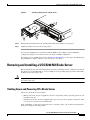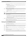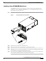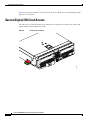
1
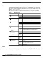
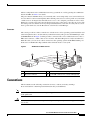
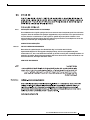
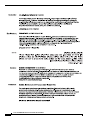
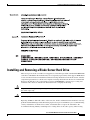
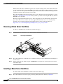
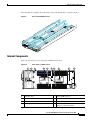
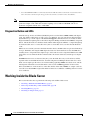
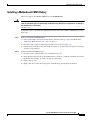
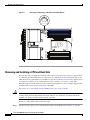
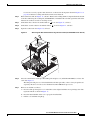
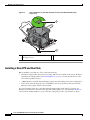
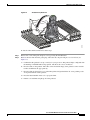
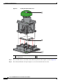
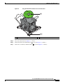
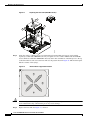
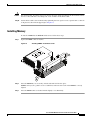
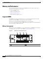
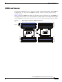
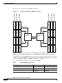
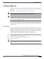
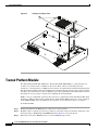
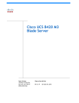
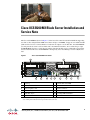
Cisco UCS B200 M3 Blade Server Installation and
Service Note
The Cisco UCS B200 M3 (shown in Figure 1) is the latest Cisco Intel-based, half-width blade supporting
two CPU sockets using Intel E5-2600 series CPUs and up to 24 DIMMs; it supports one modular LOM
(dedicated slot for Cisco's Virtual Interface Card) and one adapter card. At this time, the UCS B200 M2
(second generation) server is still available and is documented elsewhere. You can install up to eight
UCS B200 Blade Servers to a UCS chassis, mixing with other models or Cisco UCS blade servers in the
chassis if desired. The Cisco UCS B200 M3 is managed by Cisco UCS Manager version 2.0(2m) and
later.
Figure 1
Cisco UCS B200 M3 Front Panel
4
5
331360
UCS B200 M3
1
2
3
7
6
8
9
10
1
Asset tag 1
7
Network link status LED
2
Blade ejector handle
8
Blade health LED
3
Ejector captive screw
9
Console connector
4
Hard drive bay 1
10 Reset button access
5
Hard drive bay 2
11 Beaconing LED and button
6
11
Power button and LED
1.Each server has a blank plastic tag that pulls out of the front panel which is provided so that you can add your own
asset tracking label without interfering with the intended air flow.
Americas Headquarters:
Cisco Systems, Inc., 170 West Tasman Drive, San Jose, CA 95134-1706 USA
LEDs
Server LEDs indicate whether the blade server is in active or standby mode, the status of the network
link, the over all health of the blade server, and whether the server is set to give a flashing blue beaconing
indication. See Table 1 for details.
The removable hard disks also have LEDs indicating hard disk access activity and hard disk health.
Table 1
Blade Server LEDs
LED
Color
Description
Off
Power off.
Green
Normal operation.
Amber
Standby.
Off
None of the network links are up.
Green
At least one network link is up.
Off
Power off.
Green
Normal operation.
Amber
Minor error.
Blinking
Amber
Critical error.
Off
Beaconing not enabled.
Blinking
blue 1 Hz
Beaconing to locate a selected blade—If the LED is not
blinking, the blade is not selected. You can initiate
beaconing in UCS Manager or with the button.
Activity
Off
Inactive.
(Disk Drive)
Green
Outstanding I/O to disk drive.
Flashing
Amber
4 Hz
Rebuild in progress. Health LED will flash in unison.
Flashing
Amber
4 hz
Identify drive active.
Off
Can mean either no fault detected or the drive is not
installed.
Flashing
Amber
4 hz
Identify drive active. If the Activity LED is also flashing
amber, a drive rebuild is in progress.
Amber
Fault detected.
Power
Link
Health
Beaconing
Health
(Disk Drive)
Buttons
The Reset button is just inside the chassis and must be pressed using the tip of a paper clip or a similar
item. Hold the button down for five seconds, and then release it to restart the server if other methods of
restarting are not working.
Cisco UCS B200 M3 Blade Server Installation and Service Note
2
OL-26624-01
The beaconing function for an individual server may get turned on or off by pressing the combination
button and LED. See Table 1 for details.
The power button and LED allows you to manually take a server temporarily out of service but leave it
in a state where it can be restarted quickly. If the desired power state for a service profile associated with
a blade server or an integrated rack-mount server is set to "off", using the power button or Cisco UCS
Manager to reset the server will cause the desired power state of the server to become out of sync with
the actual power state and the server may unexpected shutdown at a later time. To safely reboot a server
from a power-down state, use the Boot Server action in Cisco UCS Manager.
Connectors
The console port allows a direct connection to a blade server to allow operating system installation and
other management tasks to be done directly rather than remotely. The port uses the KVM dongle cable
(N20-BKVM shown in Figure 2) which provides a connection into a Cisco UCS blade server; it has a a
DB9 serial connector, a VGA connector for a monitor, and dual USB ports for a keyboard and mouse.
With this cable, you can create a direct connection to the operating system and the BIOS running on a
blade server. A KVM cable ships standard with each blade chassis accessory kit.
Figure 2
KVM Cable for Blade Servers
4
2
3
192621
1
1
Connector to blade server slot
3
VGA connection for a monitor
2
DB9 serial connector
4
2-port USB connector for a mouse and keyboard
Conventions
This document uses the following conventions for notes, cautions, and safety warnings.
Notes and Cautions contain important information that you should know.
Note
Means reader take note. Notes contain helpful suggestions or references to material that are not covered
in the publication.
Caution
Means reader be careful. You are capable of doing something that might result in equipment damage or
loss of data.
Cisco UCS B200 M3 Blade Server Installation and Service Note
OL-26624-01
3
Safety warnings appear throughout this publication in procedures that, if performed incorrectly, can
cause physical injuries. A warning symbol precedes each warning statement.
Warning
IMPORTANT SAFETY INSTRUCTIONS
This warning symbol means danger. You are in a situation that could cause bodily injury. Before you
work on any equipment, be aware of the hazards involved with electrical circuitry and be familiar
with standard practices for preventing accidents. Use the statement number provided at the end of
each warning to locate its translation in the translated safety warnings that accompanied this
device. Statement 1071
SAVE THESE INSTRUCTIONS
Waarschuwing
BELANGRIJKE VEILIGHEIDSINSTRUCTIES
Dit waarschuwingssymbool betekent gevaar. U verkeert in een situatie die lichamelijk letsel kan
veroorzaken. Voordat u aan enige apparatuur gaat werken, dient u zich bewust te zijn van de bij
elektrische schakelingen betrokken risico's en dient u op de hoogte te zijn van de standaard
praktijken om ongelukken te voorkomen. Gebruik het nummer van de verklaring onderaan de
waarschuwing als u een vertaling van de waarschuwing die bij het apparaat wordt geleverd, wilt
raadplegen.
BEWAAR DEZE INSTRUCTIES
Varoitus
TÄRKEITÄ TURVALLISUUSOHJEITA
Tämä varoitusmerkki merkitsee vaaraa. Tilanne voi aiheuttaa ruumiillisia vammoja. Ennen kuin
käsittelet laitteistoa, huomioi sähköpiirien käsittelemiseen liittyvät riskit ja tutustu
onnettomuuksien yleisiin ehkäisytapoihin. Turvallisuusvaroitusten käännökset löytyvät laitteen
mukana toimitettujen käännettyjen turvallisuusvaroitusten joukosta varoitusten lopussa näkyvien
lausuntonumeroiden avulla.
SÄILYTÄ NÄMÄ OHJEET
Attention
IMPORTANTES INFORMATIONS DE SÉCURITÉ
Ce symbole d'avertissement indique un danger. Vous vous trouvez dans une situation pouvant
entraîner des blessures ou des dommages corporels. Avant de travailler sur un équipement, soyez
conscient des dangers liés aux circuits électriques et familiarisez-vous avec les procédures
couramment utilisées pour éviter les accidents. Pour prendre connaissance des traductions des
avertissements figurant dans les consignes de sécurité traduites qui accompagnent cet appareil,
référez-vous au numéro de l'instruction situé à la fin de chaque avertissement.
CONSERVEZ CES INFORMATIONS
Cisco UCS B200 M3 Blade Server Installation and Service Note
4
OL-26624-01
Warnung
WICHTIGE SICHERHEITSHINWEISE
Dieses Warnsymbol bedeutet Gefahr. Sie befinden sich in einer Situation, die zu Verletzungen führen
kann. Machen Sie sich vor der Arbeit mit Geräten mit den Gefahren elektrischer Schaltungen und
den üblichen Verfahren zur Vorbeugung vor Unfällen vertraut. Suchen Sie mit der am Ende jeder
Warnung angegebenen Anweisungsnummer nach der jeweiligen Übersetzung in den übersetzten
Sicherheitshinweisen, die zusammen mit diesem Gerät ausgeliefert wurden.
BEWAHREN SIE DIESE HINWEISE GUT AUF.
Avvertenza
IMPORTANTI ISTRUZIONI SULLA SICUREZZA
Questo simbolo di avvertenza indica un pericolo. La situazione potrebbe causare infortuni alle
persone. Prima di intervenire su qualsiasi apparecchiatura, occorre essere al corrente dei pericoli
relativi ai circuiti elettrici e conoscere le procedure standard per la prevenzione di incidenti.
Utilizzare il numero di istruzione presente alla fine di ciascuna avvertenza per individuare le
traduzioni delle avvertenze riportate in questo documento.
CONSERVARE QUESTE ISTRUZIONI
Advarsel
VIKTIGE SIKKERHETSINSTRUKSJONER
Dette advarselssymbolet betyr fare. Du er i en situasjon som kan føre til skade på person. Før du
begynner å arbeide med noe av utstyret, må du være oppmerksom på farene forbundet med
elektriske kretser, og kjenne til standardprosedyrer for å forhindre ulykker. Bruk nummeret i slutten
av hver advarsel for å finne oversettelsen i de oversatte sikkerhetsadvarslene som fulgte med denne
enheten.
TA VARE PÅ DISSE INSTRUKSJONENE
Aviso
INSTRUÇÕES IMPORTANTES DE SEGURANÇA
Este símbolo de aviso significa perigo. Você está em uma situação que poderá ser causadora de
lesões corporais. Antes de iniciar a utilização de qualquer equipamento, tenha conhecimento dos
perigos envolvidos no manuseio de circuitos elétricos e familiarize-se com as práticas habituais de
prevenção de acidentes. Utilize o número da instrução fornecido ao final de cada aviso para
localizar sua tradução nos avisos de segurança traduzidos que acompanham este dispositivo.
GUARDE ESTAS INSTRUÇÕES
¡Advertencia!
INSTRUCCIONES IMPORTANTES DE SEGURIDAD
Este símbolo de aviso indica peligro. Existe riesgo para su integridad física. Antes de manipular
cualquier equipo, considere los riesgos de la corriente eléctrica y familiarícese con los
procedimientos estándar de prevención de accidentes. Al final de cada advertencia encontrará el
número que le ayudará a encontrar el texto traducido en el apartado de traducciones que acompaña
a este dispositivo.
GUARDE ESTAS INSTRUCCIONES
Cisco UCS B200 M3 Blade Server Installation and Service Note
OL-26624-01
5
Varning!
VIKTIGA SÄKERHETSANVISNINGAR
Denna varningssignal signalerar fara. Du befinner dig i en situation som kan leda till personskada.
Innan du utför arbete på någon utrustning måste du vara medveten om farorna med elkretsar och
känna till vanliga förfaranden för att förebygga olyckor. Använd det nummer som finns i slutet av
varje varning för att hitta dess översättning i de översatta säkerhetsvarningar som medföljer denna
anordning.
SPARA DESSA ANVISNINGAR
Cisco UCS B200 M3 Blade Server Installation and Service Note
6
OL-26624-01
Aviso
INSTRUÇÕES IMPORTANTES DE SEGURANÇA
Este símbolo de aviso significa perigo. Você se encontra em uma situação em que há risco de lesões
corporais. Antes de trabalhar com qualquer equipamento, esteja ciente dos riscos que envolvem os
circuitos elétricos e familiarize-se com as práticas padrão de prevenção de acidentes. Use o
número da declaração fornecido ao final de cada aviso para localizar sua tradução nos avisos de
segurança traduzidos que acompanham o dispositivo.
GUARDE ESTAS INSTRUÇÕES
Advarsel
VIGTIGE SIKKERHEDSANVISNINGER
Dette advarselssymbol betyder fare. Du befinder dig i en situation med risiko for
legemesbeskadigelse. Før du begynder arbejde på udstyr, skal du være opmærksom på de
involverede risici, der er ved elektriske kredsløb, og du skal sætte dig ind i standardprocedurer til
undgåelse af ulykker. Brug erklæringsnummeret efter hver advarsel for at finde oversættelsen i de
oversatte advarsler, der fulgte med denne enhed.
GEM DISSE ANVISNINGER
Cisco UCS B200 M3 Blade Server Installation and Service Note
OL-26624-01
7
Cisco UCS B200 M3 Blade Server Installation and Service Note
8
OL-26624-01
Installing and Removing a Blade Server Hard Drive
Installing and Removing a Blade Server Hard Drive
There are up to two front-accessible, hot-swappable, 2.5-inch drives per blade. An LSI SAS 2004 RAID
controller is embedded in the motherboard (it is not separately replaceable), and it supports RAID 0 and
1. You can remove blade server hard drives without removing the blade server from the chassis. All other
component replacements for a blade server requires removing the blade from the chassis. Unused hard
drive bays should always be covered with cover plates (N20-BBLKD) to ensure proper cooling and
ventilation. The chassis is omitted from illustrations here to simplify the drawing.
Caution
To prevent ESD damage, wear grounding wrist straps during these procedures and handle modules by
the carrier edges only.
Caution
RAID array migration between a B200 M1 or B200 M2 and a B200 M3 is not supported
Replacing an HDD or SSD with a drive of the same size, model, and manufacturer should not cause any
problems with UCS Manager. If the drive being replaced was part of a RAID array. we recommend using
a newly ordered drive of identical size, model, and manufacturer to replace the failed drive. We
recommend following industry standard practice of using drives of the same capacity when creating
Cisco UCS B200 M3 Blade Server Installation and Service Note
OL-26624-01
9
Installing and Removing a Blade Server Hard Drive
RAID volumes. If drives of different capacities are used, the useable portion of the smallest drive will
be used on all drives that make up the RAID volume. Before upgrading or adding an HDD to a running
system, check the service profile in UCS Manager to make sure that the new hardware configuration is
within the parameters allowed by the service profile.
Hard disk and RAID troubleshooting information is in the "Troubleshooting Server Hardware" chapter
of the Cisco UCS Troubleshooting Guide. This provides a procedure for moving a RAID array between
B200 M3 servers if needed.
The drives supported in this blade server are all hot pluggable and come with the drive sled attached.
Spare drive sleds are not available. The drives supported in this blade server are constantly being
updated. A list of currently supported and available drives is in the specification sheets at:
http://www.cisco.com/en/US/products/ps10280/products_data_sheets_list.html
Removing a Blade Server Hard Drive
To remove a hard drive from a blade server, follow these steps:
Step 1
Push the button to release the ejector, and then pull the hard drive from its slot.
Figure 3
Removing the Hard Drive
3
331362
2
1
Step 2
Place the hard drive on an antistatic mat or antistatic foam if you are not immediately reinstalling it in
another server.
Step 3
Install a hard disk drive blank faceplate (N20-BBLKD) to keep dust out of the blade server if the slot
will remain empty.
Installing a Blade Server Hard Drive
To install a blade server hard drive in a blade server, follow these steps:
Step 1
Place the hard drive lever into the open position by pushing the release button (see Figure 4).
Cisco UCS B200 M3 Blade Server Installation and Service Note
10
OL-26624-01
Removing and Installing a UCS B200 M3 Blade Server
Installing a Hard Drive in a Blade Server
331363
Figure 4
2
1
Step 2
Gently slide the hard drive into the opening in the blade server until it seats into place.
Step 3
Push the hard drive lever into the closed position.
You can use UCS Manager to format and configure RAID services. Refer to the UCS Manager
configuration guide for your software release for details on RAID configuration.
If you need to move a RAID cluster, refer to the Moving a RAID Cluster section of the "Troubleshooting
Server Hardware" chapter of the Cisco UCS Troubleshooting Guide.
Removing and Installing a UCS B200 M3 Blade Server
Before performing any of the following internal operations on this blade server, you must remove it from
the chassis. To prevent ESD damage, wear grounding wrist straps during these procedures and handle
modules by the carrier edges only.
Caution
To prevent ESD damage, wear grounding wrist straps during these procedures and handle modules by
the carrier edges only.
Shutting Down and Powering Off a Blade Server
The server can run in two power modes:
•
Main power mode—Power is supplied to all server components, and any operating system on your
hard drives can run.
•
Standby power mode—Power is supplied only to the service processor and the cooling fans, and it
is safe to power off the server from this mode.
After establishing a connection to the blade server’s operating system, you can directly shut down the
blade server using the operating system.
Cisco UCS B200 M3 Blade Server Installation and Service Note
OL-26624-01
11
Removing and Installing a UCS B200 M3 Blade Server
You can invoke a graceful shutdown or an emergency shutdown (hard shutdown) by using either of the
following methods:
•
Use the UCS Manager. See either the Cisco UCS Manager GUI Configuration Guide or the Cisco
UCS Manager CLI Configuration Guide.
•
Use the Power button on the server front panel.
To use the Power button, follow these steps:
Step 1
Step 2
Caution
Step 3
Check the color of the Power Status LED.
•
Green indicates that the server is in main power mode and must be shut down before it can be safely
powered off. Go to Step 2.
•
Amber indicates that the server is already in standby mode and can be safely powered off. Go to
Step 3.
Invoke either a graceful shutdown or a hard shutdown:
To avoid data loss or damage to your operating system, you should always invoke a graceful shutdown
of the operating system.
•
Graceful shutdown—Press and release the Power button. The operating system performs a graceful
shutdown and the server goes to standby mode, which is indicated by an amber Power Status LED.
•
Emergency shutdown—Press and hold the Power button for 4 seconds to force the main power off
and immediately enter standby mode.
If you are shutting down all blade servers in a chassis, you should now disconnect the power cords from
the chassis to completely power off the servers. If you are only shutting down one server, you can skip
unplugging the chassis and move to removing the server.
Removing a Cisco UCS B200 M3 Blade Server
Using UCS Manager, decommission the server before physically removing the server. To remove a blade
server from the chassis, follow these steps:
Step 1
Loosen the captive screw on the front of the blade.
Step 2
Remove the blade from the chassis by pulling the ejector lever on the blade until it unseats the blade
server.
Step 3
Slide the blade part of the way out of the chassis, and place your other hand under the blade to support
its weight.
Step 4
Once removed, place the blade on an antistatic mat or antistatic foam if you are not immediately
reinstalling it into another slot.
Step 5
If the slot is to remain empty, install a blank faceplate (N20-CBLKB1) to keep dust out of the chassis.
Cisco UCS B200 M3 Blade Server Installation and Service Note
12
OL-26624-01
Removing and Installing a UCS B200 M3 Blade Server
Installing a Cisco UCS B200 M3 Blade Server
UCS B200 M3 blade servers are interoperable in a UCS chassis with any other UCS blade servers,
including prior generation B200 M2 and B200 M1 servers, or other UCS B-Series blade servers. To
install a blade server, follow these steps:
Step 1
Grasp the front of the blade server and place your other hand under the blade to support it. See Figure 5.
Positioning a Blade Server in the Chassis
331364
Figure 5
Step 2
Open the ejector lever in the front of the blade server.
Step 3
Gently slide the blade into the opening until you cannot push it any farther.
Step 4
Press the ejector lever so that it catches the edge of the chassis and presses the blade server all the way in.
Step 5
Tighten the captive screw on the front of the blade to no more than 3 in-lbs. Tightening with bare fingers
only is unlikely to lead to stripped or damaged captive screws.
Step 6
Power on the server. UCS Manager automatically reacknowledges, reassociates, and recommissions the
server, provided any hardware changes are allowed by the service profile.
Cisco UCS B200 M3 Blade Server Installation and Service Note
OL-26624-01
13
Secure Digital (SD) Card Access
Figure 5 shows the positioning of a blade server in the chassis. Blade servers reside within the eight
upper slots of the chassis.
Secure Digital (SD) Card Access
SD card slots are provided for future usage. Their use is not supported at product release. They will
require a future software update to be used.
SD Card Slot Locations
332219
Figure 6
Cisco UCS B200 M3 Blade Server Installation and Service Note
14
OL-26624-01
Removing a Blade Server Cover
Removing a Blade Server Cover
To open a blade server, follow these steps:
Step 1
Press and hold the button down as shown in Figure 7.
Step 2
While holding the back end of the cover, pull the cover up and back.
Figure 7
Opening a Cisco UCS B200 M3 Blade Server
331365
2
1
Cisco UCS B200 M3 Blade Server Installation and Service Note
OL-26624-01
15
Removing a Blade Server Cover
Air Baffles
The air baffles (shown in Figure 8) direct and improve air flow for the server components. Two identical
baffles ship with each B200 M3 server. No tools are necessary to install them, just place them over the
DIMMs as shown, with the holes in the center of the baffles aligned with the corresponding motherboard
standoffs.
Cisco UCS B200 M3 Air Baffles
331366
Figure 8
Cisco UCS B200 M3 Blade Server Installation and Service Note
16
OL-26624-01
Removing a Blade Server Cover
Once installed, the air baffles direct the intake air into four distinct lanes as shown in Figure 9.
Cisco UCS B200 M3 Air Flow
331731
Figure 9
Internal Components
Figure 10 calls out the various components within the blade server.
Figure 10
Inside View of a Blade Server
1
2
3
4
5
6
5
4
7
C0
C1
C2
D0
D1
D2
8
E0
E1
E2
F0
F1
F2
CPU 2
H2
H1
H0
G2
G1
G0
B2
B1
B0
A2
A1
A0
1
Hard drive bays
2
Internal USB connector 1
3
Battery
4
CPU and heat sink
5
DIMM slots
6
Diagnostic button
7
Modular LOM (shown installed)
8
Adapter card connector
(Adapter not shown installed)
331367
CPU 1
Cisco UCS B200 M3 Blade Server Installation and Service Note
OL-26624-01
17
Working Inside the Blade Server
1. Cisco UCS-USBFLSH-S-4GB= is recommended, but if another USB drive will be used it must be no wider than .8 inches,
and no more than 1.345 inches long in order tp provide needed clearances to install or remove the USB drive.
Note
Use of this server may require an upgrade to the IOM in the chassis. This server only supports third
generation adapter cards, which have features requiring a Cisco 2204 or 2208 IOM, and are not
backward compatible with the Cisco 2104 IOM.
Diagnostics Button and LEDs
At blade start-up, Power-on Self Test (POST) diagnostics test the CPUs, DIMMs, HDDs and adapter
cards. Any failure notifications are sent to Cisco Ucs Manager. You can view these notification in the
System Error Log or in the output of the show tech-support command. If errors are found, an amber
diagnostic LED also lights up next to the failed component. During run time, the blade BIOS, component
drivers, and OS all monitor for hardware faults and the amber diagnostic LED for a component lights up
if an uncorrectable error or correctable errors (such as a host ECC error) over the allowed threshold
occur.
LED states are saved. If you remove the blade from the chassis, the LED values are preserved in memory
for up to 10 minutes. Pressing the LED diagnostics button on the motherboard causes the LEDs that
currently show a component fault to light for up to 30 seconds for easier component identification. LED
fault values are reset when the blade is reinserted into the chassis and booted, and the process begins
again.
If DIMM insertion errors are detected, they may cause the blade discovery to fail and errors will be
reported in the server POST information, viewable using the UCS Manager GUI or CLI. Cisco UCS
blade servers require specific rules to be followed when populating DIMMs in a blade server, and the
rules depend on the blade server model. Refer to the section on DIMM population for those rules.
Drive status LEDs are on the front face of the drive. Faults on the CPU, DIMMs, or adapter cards also
cause the server health LED to light solid amber for minor error conditions or blinking amber for critical
error conditions.
Working Inside the Blade Server
This section describes how to perform the following tasks within a blade server:
•
Installing a Motherboard CMOS Battery, page 19
•
Removing and Installing a CPU and Heat Sink, page 20
•
Installing Memory, page 27
•
Installing an Adapter Card, page 33
Cisco UCS B200 M3 Blade Server Installation and Service Note
18
OL-26624-01
Working Inside the Blade Server
Installing a Motherboard CMOS Battery
This server supports the CR2032 CMOS battery (N20-MBLIBATT).
Warning
There is danger of explosion if the battery is replaced incorrectly. Replace the battery only with the
same or equivalent type recommended by the manufacturer. Dispose of used batteries according to
the manufacturer’s instructions.
Statement 1015
To install or replace a motherboard complementary metal-oxide semiconductor (CMOS) battery, follow
these steps:
Step 1
Step 2
Remove a motherboard CMOS battery:
a.
Power off the blade, remove it from the chassis, and remove the top cover as described in the
“Removing a Blade Server Cover” section on page 15.
b.
Press the battery socket retaining clip toward the chassis wall (see Figure 11).
c.
Lift the battery from the socket. Use needle-nose pliers to grasp the battery if there is not enough
clearance for your fingers.
Install a motherboard CMOS battery:
a.
Press the battery socket retaining clip toward the chassis wall.
b.
Insert the new battery into the socket with the battery’s negative (–) marking toward the chassis wall.
Ensure that the retaining clip clicks over the top of the battery.
c.
Replace the top cover.
d.
Replace the server in the chassis and power on the blade by pressing the Power button.
Cisco UCS B200 M3 Blade Server Installation and Service Note
OL-26624-01
19
Working Inside the Blade Server
Figure 11
Removing and Replacing a Motherboard CMOS Battery
+
C0
C1
C2
D0
D1
D2
B2
B1
B0
A2
A1
A0
331368
CPU 1
Removing and Installing a CPU and Heat Sink
You can only order your blade server with two CPUs, but at some point you may choose to upgrade them
to a different type. Both CPUs must be of the same type, and memory in slots intended for the second
CPU will not be recognized if the second CPU is not present (see Memory Arrangement). You may need
to use these procedures to move a CPU from one server to another, or to replace a faulty CPU.
The CPUs supported in this blade server are constantly being updated, a list of currently supported and
available CPUs is in the specification sheets at this URL:
http://www.cisco.com/en/US/products/ps10280/products_data_sheets_list.html
Caution
The CPU pick and place tool shown in Figure 13 and Figure 15 is required to prevent damage to the
connection pins between the motherboard and the CPU. Do not attempt this procedure without the
required tool, which is included with each CPU option kit.
To remove a CPU and heat sink, follow these steps:
Step 1
Unscrew the four captive screws securing the heat sink to the motherboard. See Figure 12, callout 1.
Cisco UCS B200 M3 Blade Server Installation and Service Note
20
OL-26624-01
Working Inside the Blade Server
Loosen one screw by a quarter turn, then move to the next in the X pattern shown in Figure 17 on
page 26. Continue loosening until the heat sink can be lifted off.
Step 2
Remove the heat sink. See Figure 12, callout 2. Remove the existing thermal compound from the bottom
of the heat sink using the cleaning kit (UCSX-HSCK= ) included with each CPU option kit. Follow the
instructions on the two bottles of cleaning solvent.
Step 3
Unhook the first socket hook, marked with an
Step 4
Unhook the second socket hook, marked with an
Step 5
Open the socket latch. See Figure 12, callout 5.
Figure 12
icon. See Figure 12, callout 3.
icon. See Figure 12, callout 4.
Removing the Heat Sink and Accessing the CPU Socket (UCS B200 M3 Server Shown)
1
2
1
1
1
4
3
331369
5
Step 6
Press the central button on the provided CPU pick and place tool (UCS-CPU-EP-PNP=) to release the
catch. See Figure 13.
The CPU pick and place tool is included with each CPU option kit, or the tool may be purchased
separately. Be sure to use the tool for the Intel Xeon E5-2600 Series processors.
Step 7
Remove an old CPU as follows:
a.
Place the CPU pick and place tool on the CPU socket aligned with the arrow pointing to the CPU
registration mark as shown in Figure 13.
b.
Press the button/handle on the tool to grasp the installed CPU.
c.
Lift the tool and CPU straight up.
Cisco UCS B200 M3 Blade Server Installation and Service Note
OL-26624-01
21
Working Inside the Blade Server
Figure 13
Proper Alignment of CPU Pick and Place Tool (for Intel Xeon E5-2600 Series
Processors)
2
1
Alignment mark on the button/handle of the
pick and place tool
2
331370
1
Alignment mark on the socket
Installing a New CPU and Heat Sink
Before installing a new CPU in a server, verify the following:
•
The CPU is supported for that given server model. This may be verified via the server's Technical
Specifications ordering guides (see Installing Memory, page 27) or by the relevant release of the
Cisco UCS Capability Catalog.
•
A BIOS update is available and installed that supports the CPU and the given server configuration.
•
If the server will be managed by Cisco UCS Manager, the service profile for this server in UCS
Manager will recognize and allow the new CPU.
If you are installing a CPU in a socket that had been shipped empty, there will be a protective cap
intended to prevent bent or touched contact pins. The pick and pull cap tool provided (See Figure 14)
can be used in a manner similar to a pair of tweezers. Grasp the protective cap and pivot as shown.
Cisco UCS B200 M3 Blade Server Installation and Service Note
22
OL-26624-01
Working Inside the Blade Server
Protective Cap Removal
333565
Figure 14
To install a CPU and heat sink, follow these steps:
Step 1
Release the catch on the pick and place tool by pressing the handle/button.
Step 2
Remove the new CPU from the packaging, and load it into the pick and place tool as follows (see
Figure 15):
a.
Confirm that the pedestal is set up correctly for your processor. The pedestal ships configured with
the markings “LGA2011-R0” facing upward, and this is the correct orientation.
b.
Place the CPU on the pedestal. The CPU corners should fit snugly at the pedestal corners and the
notches should meet the pegs perfectly.
c.
Place the CPU pick and place tool on the CPU pedestal aligned with the A1 arrow pointing to the
A1 registration mark on the pedestal.
d.
Press the button/handle on the tool to grasp the CPU.
e.
Lift the tool and CPU straight up off of the pedestal.
Cisco UCS B200 M3 Blade Server Installation and Service Note
OL-26624-01
23
Working Inside the Blade Server
Figure 15
Loading the Pick and Place Tool
1
1
1
333566
1
Alignment mark on the pick and place tool,
CPU and pedestal
Step 3
Place the CPU and tool on the CPU socket with the registration marks aligned as shown in Figure 16.
Step 4
Press the button/handle on the pick and place tool to release the CPU into the socket.
Cisco UCS B200 M3 Blade Server Installation and Service Note
24
OL-26624-01
Working Inside the Blade Server
Figure 16
Using the CPU Pick and Place Tool to Insert the CPU
2
1
Alignment mark on the tool button/handle
Step 5
Close the socket latch. See Figure 17, callout 1.
Step 6
Secure the first hook, marked with an
Step 7
Secure the second hook, marked with an
2
331370
1
Alignment mark on the CPU socket
icon. See Figure 17, callout 2.
icon. See Figure 17, callout 3.
Cisco UCS B200 M3 Blade Server Installation and Service Note
OL-26624-01
25
Working Inside the Blade Server
Figure 17
Replacing the Heat Sink (B200 M3 Shown)
3
4
2
1
5
4
5
5
5
1
3
331372
2
Step 8
Using the syringe of thermal grease provided with replacement CPUs and servers (and available
separately as UCS-CPU-GREASE=, the only exceptions are Cisco UCS C220 M3 and and C240 M3
servers which use UCS-CPU-GREASE2= instead), add 2 cubic centimeters of thermal grease to the top
of the CPU where it will contact the heat sink. Use the pattern shown in Figure 18. This should require
half the contents of the syringe.
Thermal Grease Application Pattern
334295
Figure 18
Caution
Step 9
The thermal grease has very specific thermal properties, and thermal grease from other sources should
not be substituted. Using other thermal grease may lead to damage.
Replace the heat sink. See Figure 17, callout 4.
Cisco UCS B200 M3 Blade Server Installation and Service Note
26
OL-26624-01
Working Inside the Blade Server
Caution
Step 10
On certain models, heat sinks are keyed to fit into the plastic baffle extending from the motherboard. Do
not force a heat sink if it is not fitting well, rotate it and re-orient the heat sink.
Secure the heat sink to the motherboard by tightening the four captive screws a quarter turn at a time in
an X pattern as shown in the upper right of Figure 17.
Installing Memory
To install a DIMM into the B200 M3 blade server, follow these steps:
Step 1
Open both DIMM connector latches.
Figure 19
Installing DIMMs in the Blade Server
1
3
331373
2
2
1
3
Step 2
Press the DIMM into its slot evenly on both ends until it clicks into place.
DIMMs are keyed, if a gentle force is not sufficient, make sure the notch on the DIMM is correctly
aligned.
Step 3
Press the DIMM connector latches inward slightly to seat them fully.
Cisco UCS B200 M3 Blade Server Installation and Service Note
OL-26624-01
27
Memory and Performance
Memory and Performance
This section describes the type of memory that the B200 M3 blade server requires, and its effect on
performance. The following topics are covered:
•
Supported DIMMs, page 28
•
Memory Arrangement, page 28
•
Memory Performance, page 31
•
Memory Mirroring and RAS, page 31
Supported DIMMs
The DIMMs that are supported in this blade server are constantly being updated. A list of currently
supported and available DIMMs is in the specification sheets at this URL:
http://www.cisco.com/en/US/products/ps10280/products_data_sheets_list.html
Cisco does not support third-party memory DIMMs, and in some cases their use may irreparably damage
the server and require an RMA and down time.
Memory Arrangement
The blade server contains 24 DIMM slots—12 for each CPU. Each set of 12 DIMM slots is arranged into
four channels, where each channel has three DIMMs (see Figure 20 and Figure 21).
Figure 20
Memory Slots within the Blade Server
1
1
2
2
CPU 2
331374
CPU 1
1
Channels A-D for CPU 1
2
Channels E-H for CPU 2
Cisco UCS B200 M3 Blade Server Installation and Service Note
28
OL-26624-01
Memory and Performance
DIMMs and Channels
Each channel is identified by a letter—A, B, C, D for CPU1, and E, F, G, H for CPU 2. Each DIMM slot
is numbered 0, 1, or 2. Note that each DIMM slot 0 is blue, each slot 1 is black, and each slot 2 is
off-white or beige.
Figure 21 shows how DIMMs and channels are physically laid out on the blade server. The DIMM slots
in the upper and lower right are associated with the second CPU (CPU shown on right in the diagram),
while the DIMM slots in the upper and lower left are associated with the first CPU (CPU shown on left).
Figure 21
Battery
Physical Representation of DIMMs and Channels
C0
C1
C2
D0
D1
D2
E0
E1
E2
F0
F1
F2
CPU 2
H2
H1
H0
G2
G1
G0
B2
B1
B0
A2
A1
A0
331375
CPU 1
Cisco UCS B200 M3 Blade Server Installation and Service Note
OL-26624-01
29
Memory and Performance
Figure 22 shows a logical view of the DIMMs and channels.
Channel F
F0
Logical DIMM 3
E2
Logical DIMM 2
E1
331376
G2
Channel H
H2
Channel D
G1
Channel G
H1
Channel C
G0
CPU 2
C0
D0
C1
D1
D2
C2
CPU 1
F2
Channel B
F1
Logical DIMM 1
Channel E
H0
Logical DIMM1
A0
E0
Channel A
B0
Logical DIMM 2
A1
B1
B2
Logical DIMM 3
Logical Representation of DIMMs and Channels
A2
Figure 22
DIMMs can be used in the blade server in a one DIMM per Channel (1DPC) configuration, in a two
DIMMs per Channel (2DPC) configuration, or a three DIMMs per Channel (3DPC) configuration.
Each CPU in a Cisco UCS B200 M3 blade server supports four channels of three memory slots each. In
a 1 DPC configuration, DIMMs are in slot 0 only. In a 2 DPC configuration, DIMMs are in both slot 0
and slot 1. In a 3 DPC configuration, DIMMs are in slot 0, slot 1, and slot 2.
Table 2 shows the supported order for installing upgrade DIMMs.
Table 2
Preferred DIMM Population Order
DIMMs per CPU
CPU 1 installed slots
CPU 2 installed slots
1
A0
E0
2
A0, B0
E0, F0
3
A0, B0, C0
E0, F0, G0
Cisco UCS B200 M3 Blade Server Installation and Service Note
30
OL-26624-01
Memory and Performance
Table 2
Preferred DIMM Population Order
DIMMs per CPU
CPU 1 installed slots
CPU 2 installed slots
4 (Blue slots)
A0, B0, C0, D0
E0, F0, G0, H0
5
A0, B0, C0, D0
A1
E0, F0, G0, H0
E1
6
A0, B0, C0, D0
A1, B1
E0, F0, G0, H0
E1, F1
7
A0, B0, C0, D0
A1, B1, C1
E0, F0, G0, H0
E1, F1, G1
8 (Blue and black slots)
A0, B0, C0, D0
A1, B1, C1, D1
E0, F0, G0, H0
E1, F1, G1, H1
9
A0, B0, C0, D0
A1, B1, C1, D1
A2
E0, F0, G0, H0
E1, F1, G1, H1
E2
10
A0, B0, C0, D0
A1, B1, C1, D1
A2, B2
E0, F0, G0, H0
E1, F1, G1, H1
E2, F2
11
A0, B0, C0, D0
A1, B1, C1, D1
A2, B2, C2
E0, F0, G0, H0
E1, F1, G1, H1
E2, F2, G2
12 (Blue, black and beige slots)
A0, B0, C0, D0
A1, B1, C1, D1
A2, B2, C2, D2
E0, F0, G0, H0
E1, F1, G1, H1
E2, F2, G2, H2
Memory Performance
When considering the memory configuration of your blade server, there are several things you need to
consider. For example:
•
When mixing DIMMs of different densities, the highest density DIMM goes in slot 0 then in
descending density (ex: A0: UCS-MR-1X162RY-A , A1: UCS-MR-1X082RY-A, A2:
UCS-MR-1X041RY-A)
•
Your selected CPU(s) can have some affect on performance.
•
DIMMs can be run in a 1DPC, a 2DPC, or a 3DPC configuration. 1 DPC and 2DPC can provide the
maximum rated speed that the CPU and DIMMs are rated for. 3DPC causes the DIMMs to run at a
slower speed.
Memory Mirroring and RAS
The Intel E5-2600 CPUs within the blade server support memory mirroring only when an even number
of Channels are populated with DIMMs. If one or three channels are populated with DIMMs, memory
mirroring is automatically disabled. Furthermore, if memory mirroring is used, DRAM size is reduced
by 50 percent for reasons of reliability.
Cisco UCS B200 M3 Blade Server Installation and Service Note
OL-26624-01
31
Memory and Performance
Installing a Modular LOM
The Cisco VIC 1240 is a specialized modular Lan on Motherboard (mLOM) adapter that provides dual
2 x 10 Gb of Ethernet/ or Fiber Channel over Ethernet (FCoE) connectivity to each chassis. It plugs into
the dedicated mLOM connector only. It is currently the only card that can be plugged into the mLOM
connector and it will provide connectivity through either a 2100 series or 2200 series IOM.
Note
You must remove the adapter card to service the modular LOM.
To install a modular LOM card on the blade server, follow these steps:
Step 1
Position the modular LOM’s board connector above the motherboard connector and align the captive
screw to the standoff post on the motherboard.
Step 2
Firmly press the modular LOM’s board connector into the motherboard connector.
Step 3
Tighten the captive screw.
Tip
To remove a modular LOM , reverse the above procedure. You might find it helpful when removing the
connector from the motherboard to gently rock the board along the length of the connector until it
loosens.
Figure 23
Installing a Modular LOM
3
2
332218
1
Cisco UCS B200 M3 Blade Server Installation and Service Note
32
OL-26624-01
Memory and Performance
Installing an Adapter Card
The network adapters and interface cards all have a shared installation process and are constantly being
updated. A list of currently supported and available models for this server is in the specification sheets
at this URL:
http://www.cisco.com/en/US/products/ps10280/products_data_sheets_list.html
Note
If a VIC 1240 mLOM is not installed, you must have an adapter card installed.
Note
Use of the adapters available for this server might require an upgrade to the IOM in the chassis. The
2104XP IOM is not compatible with any Cisco-certified adapter. If a VIC 1240 mLOM card is installed,
you will have connectivity through the mLOM but other adapters will not be recognized. Use of adapter
slots requires Cisco UCS 2200 series IOMs.
If you are switching from one type of adapter card to another, before you physically perform the switch
make sure that you download the latest device drivers and load them into the server’s operating system.
For more information, see the firmware management chapter of one of the Cisco UCS Manager software
configuration guides.
Adapter Slot Drives
The Cisco UCS 785GB MLC Fusion-io Drive and LSI 400GB SLC WarpDrive have the same form factor
as M3 adapter cards and can be installed and removed using the same procedures. Using these drives in
a B200 M3 or B22 M3 blade server requires the presence of a VIC 1240 mLOM to provide blade I/O.
They will not work in M1 and M2 generation Cisco UCS servers, and can be mixed with an adapter in
the B420 M3 server. These drives appear in Cisco UCS Manager as regular SSDs.
To install an adapter card or adapter slot drive on the blade server, follow these steps:
Step 1
Position the adapter board connector above the motherboard connector and align the two adapter captive
screws to the standoff posts on the motherboard.
Step 2
Firmly press the adapter connector into the motherboard connector.
Step 3
Tighten the two captive screws.
Tip
Removing an adapter card is the reverse of installing it. You may find it helpful when removing the
connector from the motherboard to gently rock the board along the length of the connector until it
loosens.
Cisco UCS B200 M3 Blade Server Installation and Service Note
OL-26624-01
33
Trusted Platform Module
Figure 24
Installing an Adapter Card
3
2
1
331730
1
Trusted Platform Module
The Trusted Platform Module (TPM, Cisco Product ID UCSX-TPM1-001) is a component that can
securely store artifacts used to authenticate the server. These artifacts can include passwords,
certificates, or encryption keys. A TPM can also be used to store platform measurements that help ensure
that the platform remains trustworthy. Authentication (ensuring that the platform can prove that it is what
it claims to be) and attestation (a process helping to prove that a platform is trustworthy and has not been
breached) are necessary steps to ensure safer computing in all environments.
TPM is a factory-configurable option for this server. It is a requirement for the Intel Trusted Execution
Technology (TXT) security feature, which must be enabled in the BIOS settings for a server equipped
with a TPM. A TPM can not be added later by customers, or moved from one server to another.
To enable the TPM:
Step 1
Enable Quiet Mode in the BIOS policy of the server’s Service Profile.
Step 2
Establish a direct connection to the server, either by connecting a keyboard, monitor, and mouse to the
front panel using a KVM dongle (N20-BKVM shown in Figure 2) or by other means.
Step 3
Reboot the server. Press F2 during reboot to enter the BIOS setup screens.
Cisco UCS B200 M3 Blade Server Installation and Service Note
34
OL-26624-01
Server Troubleshooting
Step 4
On the Advanced tab, select Trusted Computing and press Enter.
Step 5
Set the TPM Support optionto Enable.
Step 6
Press F10 to save and exit. Allow the server to finish booting.
Server Troubleshooting
For general server troubleshooting information, refer to the "Troubleshooting Server Hardware" chapter
of the Cisco UCS Troubleshooting Guide.
Server Configuration
UCS servers are intended to be configured and managed using UCS Manager. Refer to the UCS Manager
Configuration Guide appropriate for your UCS Manager version.
Server Specifications
Table 3
Physical Specifications for the Cisco UCS B200 M3 Blade Server
Specification
Value
Height
1.95 inches (50 mm)
Width
8.00 inches (203 mm)
Depth
24.4 inches (620 mm)
Weight
15.0 lbs (6.8 kg) 1
1. The system weight listed here is an estimate for a fully configured system and will vary depending on peripheral devices
installed.
Related Documentation
The documentation set for the Cisco Unified Computing System environment is described in full at:
http://www.cisco.com/go/unifiedcomputing/b-series-doc
For specifics on which components are supported refer to the server's Technical Specifications ordering
guide at the following link:
http://www.cisco.com/en/US/products/ps10493/products_data_sheets_list.html
Cisco UCS B200 M3 Blade Server Installation and Service Note
OL-26624-01
35
Related Documentation
Obtaining Documentation and Submitting a Service Request
For information on obtaining documentation, submitting a service request, and gathering additional
information, see the monthly What’s New in Cisco Product Documentation, which also lists all new and
revised Cisco technical documentation, at:
http://www.cisco.com/en/US/docs/general/whatsnew/whatsnew.html
Subscribe to the What’s New in Cisco Product Documentation as an RSS feed and set content to be
delivered directly to your desktop using a reader application. The RSS feeds are a free service. Cisco currently
supports RSS Version 2.0.
Cisco and the Cisco logo are trademarks or registered trademarks of Cisco and/or its affiliates in the U.S. and other countries. To view a list of
Cisco trademarks, go to this URL: www.cisco.com/go/trademarks. Third-party trademarks mentioned are the property of their respective owners. The
use of the word partner does not imply a partnership relationship between Cisco and any other company. (1110R)
Any Internet Protocol (IP) addresses and phone numbers used in this document are not intended to be actual addresses and phone numbers. Any
examples, command display output, network topology diagrams, and other figures included in the document are shown for illustrative purposes only.
Any use of actual IP addresses or phone numbers in illustrative content is unintentional and coincidental.
© 2012 Cisco Systems, Inc. All rights reserved.
Cisco UCS B200 M3 Blade Server Installation and Service Note
36
OL-26624-01