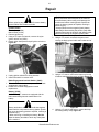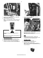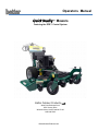
1
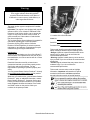
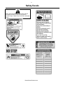
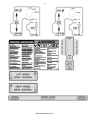
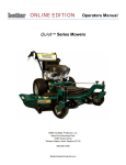
Operators Manual
Quick Dually™ Mowers
Featuring the EZR™ Control System
Better Outdoor Products, LLC
West Point Business Park
2595 Viceroy Drive
Winston-Salem, North Carolina 27103
866-290-7295
BetterOutdoorProducts.com
2
Warning
CALIFORNIA Proposition 65 Warning.
The engine exhaust from this product
contains chemicals known to the State of
California to cause cancer, birth defects, or
other reproductive harm.
This spark ignition system complies with Canadian
ICES-002.
Important: This engine is not equipped with a spark
arrester muffler. It is a violation of California Public
Resource Code Section 4442 to use or operate the
engine on any forest-covered, brush-covered, or
grass-covered land. Other states or federal areas
may have similar laws.
The enclosed Engine Owner’s Manual is supplied for
information regarding the US Environmental
Protection Agency (EPA) and the California
Emission Control Regulation of emission systems,
maintenance, and warranty. Replacements may be
ordered through the engine manufacturer.
Introduction
Thank you for purchasing one of our Quick Dually™
series mowers. If this product does not work to your
total satisfaction, let us know and we will do our best
to make it right.
Read this information carefully to learn how to
operate and maintain your product properly and to
avoid injury and product damage. You are
responsible for operating the product properly and
safely.
You may contact Better Outdoor Products™ directly
at [email protected] for product
and accessory information.
Whenever you need service, genuine Better Outdoor
Products™ parts, or additional information, contact
Better Outdoor Products™ Customer Service and
have the model and serial numbers of your product
ready. Figure 1 identifies the location of the model
and serial number on the product. Write your
numbers in the space provided.
Figure 1
1. Location of the Serial Number
Model No.
Serial No.
Purchase Date
This manual identifies potential hazards and has
safety messages identified by the following words:
• Danger signals an extreme hazard that will cause
serious injury or death if you do not follow the
recommended precautions.
• Warning signals a hazard that may cause serious
injury or death if you do not follow the recommended
precautions.
• Caution signals a hazard that may cause minor or
moderate injury if you do not follow the
recommended precautions.
This manual uses two other words to highlight
information. Important calls attention to special
mechanical information and Note emphasizes
general information worthy of special attention.
1
BetterOutdoorProducts.com
3
Table of Contents
Introduction .......................................................................................................................................................................... 2 Safety ...................................................................................................................................................................................... 6 Safety................................................................................................................................................................................... 6 Safety Decals .......................................................................................................................................................................... 8 Product Overview .................................................................................................................................................................. 10 Controls ............................................................................................................................................................................. 10 Ignition Switch ................................................................................................................................................................... 10 Choke ................................................................................................................................................................................ 10 Throttle Control .................................................................................................................................................................. 10 Blade Engagement Control (PTO) .................................................................................................................................... 10 Motion Control Levers ....................................................................................................................................................... 10 Speed Limit Lock ............................................................................................................................................................... 10 Fuel Shut-off Valve ............................................................................................................................................................ 10 Hour Meter ......................................................................................................................................................................... 11 Attachments/Accessories .................................................................................................................................................. 11 Parking Brake/Dump Valves.............................................................................................................................................. 11 Specifications .................................................................................................................................................................... 11 Operation............................................................................................................................................................................... 12 Adding Fuel........................................................................................................................................................................ 12 Using Stabilizer/Conditioner .............................................................................................................................................. 12 Filling the Fuel Tank .......................................................................................................................................................... 12 Checking the Engine Oil Level .......................................................................................................................................... 12 Think Safety First............................................................................................................................................................... 13 Starting the Engine ............................................................................................................................................................ 13 Stopping the Engine .......................................................................................................................................................... 13 Moving Forward or Backward ............................................................................................................................................ 13 Moving Forward ................................................................................................................................................................. 13 Moving Backward .............................................................................................................................................................. 13 Stopping the Machine ........................................................................................................................................................ 13 Pushing the Machine by Hand .......................................................................................................................................... 14 Side Discharging or Mulching the Grass ........................................................................................................................... 14 Operating the Deck Engagement Control (PTO)............................................................................................................... 14 Engaging the Mower Blades (PTO) ................................................................................................................................... 14 Disengaging the Mower Blades (PTO) .............................................................................................................................. 14 The Safety Interlock System ................................................................................................................................................. 14 Understanding the Safety Interlock Systems .................................................................................................................... 14 BetterOutdoorProducts.com
4
Testing the Safety Interlock System .................................................................................................................................. 14 Wheel Drive System .......................................................................................................................................................... 14 Blade Drive System ........................................................................................................................................................... 14 Quick™ Adjustments ............................................................................................................................................................ 15 Height of Cut ...................................................................................................................................................................... 15 Belt Guard Cover ............................................................................................................................................................... 16 Wheel Tracking .................................................................................................................................................................. 16 Maintenance .......................................................................................................................................................................... 17 Servicing the Engine Oil .................................................................................................................................................... 17 Checking the Engine Oil Level .......................................................................................................................................... 17 Changing the Oil (50hrs) ................................................................................................................................................... 17 Changing the Oil Filter (100hrs) ........................................................................................................................................ 18 Servicing the Spark Plug(s) (100hrs) ................................................................................................................................ 18 Removing the Spark Plug(s).............................................................................................................................................. 18 Checking the Spark Plug(s) ............................................................................................................................................... 18 Installing the Spark Plug(s)................................................................................................................................................ 19 Air Cleaner Foam and Paper Element (25-50hrs.) ............................................................................................................ 19 Fuel Filter (200 hrs.) .......................................................................................................................................................... 19 Cooling System Maintenance ............................................................................................................................................ 19 Grease Fittings (25 hrs.) .................................................................................................................................................... 19 Caster Fork (25 hrs.) ........................................................................................................................................................ 20 Clutch (25hrs.) ................................................................................................................................................................... 20 Tires (25 hrs.) .................................................................................................................................................................... 20 EZT Hydro ......................................................................................................................................................................... 21 Battery ............................................................................................................................................................................... 21 Blade Inspection (8hrs)...................................................................................................................................................... 21 Troubleshooting .................................................................................................................................................................... 22 Repair .................................................................................................................................................................................... 23 Ignition Switch ................................................................................................................................................................... 23 Blade Engagement Interlock Switch (10081) .................................................................................................................... 23 Battery (10799) .................................................................................................................................................................. 23 Starter Solenoid (10127) ................................................................................................................................................... 24 Fuse ................................................................................................................................................................................... 24 Hour Meter (10220) ........................................................................................................................................................... 24 Motion Control Interlock Switch ......................................................................................................................................... 25 Blade Engagement Control Cable (10081) ....................................................................................................................... 25 Throttle Cable (10439) Kawasaki ...................................................................................................................................... 26 Choke Cable (10440) Electric Start ................................................................................................................................... 26 BetterOutdoorProducts.com
5
Deck Drive Belt (BOP 10596 Gates 6945) 36” Models (BOP 10476 Gates 6951) 44” Models ........................................ 27 Deck Belt (BOP 10047 Gates 6868) 36” Models (BOP 10475 Gates 6882) 44” Models .................................................. 27 Hydro Drive Belt (BOP 10706 Gates 6831) All Models ..................................................................................................... 27 Multi Disc Clutch (10579) .................................................................................................................................................. 28 Spindle (10323) ................................................................................................................................................................. 28 Spindle Pulley (10251) (10252) (10483) ........................................................................................................................... 29 Idler Pulley Replacement (10027) Deck Idler (10028) Deck Drive Idler............................................................................ 29 Idler Spring Replacement (10029) Small
(10326) Large ............................................................................................... 29 Rear Wheel ........................................................................................................................................................................ 29 Front Caster Wheel (10007) .............................................................................................................................................. 29 Engine................................................................................................................................................................................ 29 Hydro Drive Axles LH (10711), RH(10712) ....................................................................................................................... 30 Wiring Schematics ................................................................................................................................................................ 33 Accessories ........................................................................................................................................................................... 35 Mulching Kit (ACC-0013) 36” models
(ACC-0014) 44” models ............................................................................. 35 Gator Blades (ACC-0002) 36” models
(ACC-0011) 44” models ............................................................................. 35 Mulching Tips .................................................................................................................................................................... 36 Striping Roller (ACC-0009) 36” models
(ACC-0019) 44” models ............................................................................. 36 Grass Catcher (ACC-0001) ............................................................................................................................................... 36 Warranty ................................................................................................................................................................................ 37 Warranty ............................................................................................................................................................................ 37 BetterOutdoorProducts.com
6
Safety
Safety
Note: The addition of attachments made by other
manufacturers that do not meet American National
Standards Institute certification will cause
noncompliance of this machine. Improper use or
maintenance by the operator or owner can result in
injury. To reduce the potential for injury, comply with
these safety instructions and always pay attention to
the safety alert symbol
, which means CAUTION,
WARNING, or DANGER-“personal safety
instruction." Failure to comply with the instruction
may result in personal injury or death.
Safe Operating Practices
The following instructions are from ANSI standard
B71.4-2004.
Training
•
Read the Operator’s Manual and other
training material. If the operator(s) or mechanic(s)
can’t read English it is the owner’s responsibility to
explain this material to them.
• Become familiar with the safe operation of the
equipment, operator controls, and safety signs.
• All operators and mechanics should be trained.
The owner is responsible for training the users.
• Never let children or untrained people operate or
service the equipment. Local regulations may restrict
the age of the operator.
• The owner/user can prevent and is responsible for
accidents or injuries occurring to himself or herself
other people or property.
Preparation
• Evaluate the terrain to determine what accessories
and attachments are needed to properly and safely
perform the job. Only use accessories and
attachments approved by the manufacturer.
• Wear appropriate clothing including hard hat,
safety glasses and hearing protection. Long hair,
loose clothing or jewelry may get tangled in moving
parts.
• Inspect the area where the equipment is to be used
and remove all objects such as rocks, toys and wire
which can be thrown by the machine.
• Use extra care when handling gasoline and other
fuels. They are flammable and vapors are explosive.
• Use only an approved container
• Never remove gas cap or add fuel with engine
running. • Allow engine to cool before refueling.
• Do Not smoke.
• Never refuel or drain the machine indoors.
• Check that operator’s presence controls, safety
switches and shields are attached and functioning
properly. Do Not operate unless they are functioning
properly.
Operation
• Never run an engine in an enclosed area.
• Only operate in good light, keeping away from
holes and hidden hazards.
• Be sure all drives are in neutral and parking brake
is engaged before starting engine. Only start engine
from the operator’s position.
• Be sure of your footing while using this machine
especially when backing up. Walk, don’t run. Never
operate on wet grass. Reduced footing could cause
slipping.
• Slow down and use extra care on hillsides. Be sure
to travel side to side on hillsides. Turf conditions can
affect the machine’s stability. Use caution while
operating near drop-offs.
• Slow down and use caution when making turns
and when changing directions on slopes.
• Never raise deck with the blades running.
• Never operate with the mower deck belt guard, or
other guards not securely in place. Be sure all
interlocks are attached, adjusted properly, and
functioning properly.
• Never operate with the discharge deflector raised,
removed or altered, unless using a grass catcher.
• Do Not change the engine governor setting or over
speed the engine.
• Stop on level ground, disengage drives, engage
parking brake (if provided), shut off engine before
leaving the operator’s position for any reason
including emptying the catcher or unclogging the
chute.
• Stop equipment and inspect blades after striking
objects or if an abnormal vibration occurs. Make
necessary repairs before resuming operations.
• Keep hands and feet away from the cutting unit.
• Look behind and down before backing up to be
sure of a clear path.
• Keep pets and bystanders away.
• Slow down and use caution when making turns
and crossing roads and sidewalks. Stop blades if not
mowing.
• Be aware of the mower discharge direction and do
not point it at anyone.
• Do Not operate the mower under the influence of
alcohol or drugs.
• Use care when loading or unloading the machine
onto or from a trailer or truck.
• Use care when approaching blind corners, shrubs,
trees, or other objects that may obscure vision.
BetterOutdoorProducts.com
7
Maintenance and storage
• Disengage drives, set parking brake, stop engine
and remove key or disconnect spark plug wire(s).
Wait for all movement to stop before adjusting,
cleaning or repairing.
• Clean grass and debris from cutting unit, drives,
mufflers, and engine to help prevent fires. Clean up
oil or fuel spillage.
• Let engine cool before storing and Do Not store
near flame.
• Shut off fuel while storing or transporting. Do Not
store fuel near flames or drain indoors.
• Park machine on level ground. Set parking brake.
Never allow untrained personnel to service machine.
• Use jack stands to support components when
required.
• Carefully release pressure from components with
stored energy.
• Disconnect the battery or remove spark plug
wire(s) before making any repairs. Disconnect the
negative terminal first and the positive last.
Reconnect the positive first and negative last.
• Use care when checking blades. Wrap the blade(s)
or wear gloves, and use caution when servicing
them. Only replace blades. Never straighten or weld
them.
• Keep hands and feet away from moving parts. If
possible, Do Not make adjustments with the engine
running.
• Keep all parts in good working condition and all
hardware tightened. Replace all worn or damaged
decals.
Quick™ Mower Safety
The following list contains safety information specific
to Better Outdoor Products™ and other safety
information you must know. This product is capable
of amputating hands and feet and throwing objects.
Always follow all safety instructions to avoid serious
injury or death. This product is designed for cutting
and mulching grass or, when equipped with a grass
bagger, for catching cut grass. Any use for purposes
other than these could prove dangerous to user and
bystanders.
General Operation
• Be sure the area is clear of other people before
mowing. Stop the machine if anyone enters the
area.
• Do Not touch equipment or attachment parts which
may be hot from operation. Allow to cool before
attempting to maintain, adjust or service.
• Use only Better Outdoor Products™ approved
attachments. Warranty may be voided if used with
unapproved attachments.
Slope Operation
All slopes and ramps require extra caution. If you
feel uneasy on a slope, Do Not mow it.
• Remove obstacles such as rocks, tree limbs, etc.
from the mowing area.
• Watch for holes, ruts or bumps. Tall grass can hide
obstacles.
• Use caution near drop-offs, ditches, or
embankments. The machine could suddenly turn
over if a wheel goes over the edge of a cliff or ditch,
or if an edge caves in.
• Use extra care with grass catchers or other
attachments. These can change the stability of the
machine.
• Keep all movement on slopes slow and gradual.
Do Not make sudden changes in speed or direction.
• Mow slopes side to side.
• Do Not mow slopes greater than 15 degrees.
Service
• Never store the machine or fuel container inside
where there is an open flame, such as near a water
heater or furnace.
• Keep nuts and bolts tight, especially the blade
attachment bolts. Keep equipment in good condition.
• Never tamper with safety devices. Check safety
systems for proper operation before each use.
• Understand service procedure before doing work.
Keep the work area clean and dry.
• Engine exhaust fumes can cause sickness or
death. ONLY start engine outdoors or in a well
ventilated place.
• Keep cigarettes, sparks and open flames away
from the fuel system and the battery.
• Always have an approved and fully charged fire
extinguisher near your work area.
• Wear personal eye protection when using
compressed air for cleaning purposes.
• Never lubricate, service or adjust mower while it is
moving. Keep all safety devices in place and in
working condition.
• Keep hardware tight.
•To prevent them from getting caught, keep hands,
feet, clothing, jewelry and long hair away from any
moving parts.
• Before servicing machine, disengage all power and
stop the engine. Let engine cool.
• Securely support any machine elements that must
be raised for service work.
• Keep all parts in good condition and properly
installed. Fix damage immediately. Replace worn or
broken parts. Remove any buildup of grease, oil or
debris.
• Unauthorized modifications to the mower may
impair its function and safety and will void any
warranty.
BetterOutdoorProducts.com
8
Safety Decals
Safety decals and instructions are easily visible to
the operator and are located near any area of
potential danger. Replace any decal that is damaged
or lost.
BetterOutdoorProducts.com
9
BetterOutdoorProducts.com
10
Product Overview
2
Ignition Switch
This switch is used to start the mower engine.
Manual start engines have two positions: Run and
Stop. Electric start engines have three positions:
Start, Run and Stop.
4
3
1
Choke
Use the choke when starting a cold engine.
7
Throttle Control
The throttle controls engine RPM.
5
Blade Engagement Control (PTO)
The blade engagement control (PTO) is used to
engage the drive for the mower blades. Move the
lever up and to the right to engage the blades. To
disengage the blades, move the blade control lever
(PTO) down. The left side motion control lever must
be depressed for blades to engage.
6
Figure 2
1. Oil dipstick
2. Headlights
3. Gas tank
4. Gas Cap
5. Side discharge chute
6. Front caster wheel
7. Belt Guard Cover
Motion Control Levers
The motion control levers are used to drive the
machine forward, reverse and turn either direction.
Note: Determine the left and right sides of the
machine from the normal operating position.
Controls
Become familiar with all the controls (Figure 3)
before you start the engine and operate the
machine.
4
Speed Limit Lock
The speed limit lock is used to set the maximum
forward speed the machine will travel. Loosen the
locking knob and move forward to increase speed,
move it back to decrease speed.
1
2
Fuel Shut-off Valve
3
7
5
1.
2.
3.
4.
5.
6.
7.
Figure 3
Ignition Switch
Manual Choke (if equipped)
Throttle
PTO Control
Left Motion Control Lever
Right Motion Control Lever
Speed Limit Lock
6
Figure 4
Close the fuel shut-off valve (under the fuel tank)
when transporting or storing the mower.
BetterOutdoorProducts.com
11
Specifications
Note: Specifications and design are subject to
change without notice.
Hour Meter
36 inch mowers:
Width w/deflector up
Length
64 ½ inches
Height
Weight
44 inches
396-409 pounds
44 inch mowers:
Width w/deflector up
Figure 5
The hour meter shows the total hours the machine
has been operated.
The hour meter runs anytime the key is in the on
position.
Note: Check your hour meter to ensure that
maintenance is done at all recommended intervals
shown in the Recommended Maintenance
Schedule.
66 ½ inches
Height
Weight
44 inches
431-445 pounds
Parking Brake/Dump Valves
1
47 ½ inches
Length
Attachments/Accessories
A selection of Better Outdoor Products™ approved
attachments and accessories are available for use
with the machine to enhance and expand its
capabilities. Contact Better Outdoor Products™ for
information on approved accessories.
2
39 ½ inches
2
Figure 6
1. The parking brake is engaged by pulling the lever
out and locking in place. It must be disengaged for
machine to move.
2. The dump valves are located on either side of
parking brake. They are engaged by pulling out and
locking in place. This will allow the machine to be
rolled around by hand.
BetterOutdoorProducts.com
12
Operation
Adding Fuel
Use Unleaded Regular Gasoline suitable for
automotive use (85 octane minimum).
Important: Never use methanol, gasoline
containing methanol, or gasohol containing more
than 10% ethanol because the fuel system could be
damaged. Do Not mix oil with gasoline.
Gasoline is harmful or fatal if swallowed. Long-term
exposure to vapors can cause serious injury and
illness.
• Avoid prolonged breathing of vapors.
• Keep face away from nozzle and gas tank or
container opening.
• Keep gas away from eyes and skin.
In certain conditions, gasoline is extremely
flammable and highly explosive. A fire or explosion
from gasoline can burn you and others and can
damage property.
• Fill the fuel tank outdoors, in an open area, when
the engine is cold. Wipe up any gasoline that spills.
• Never fill the fuel tank inside an enclosed trailer.
• Do Not fill the fuel tank completely full. Add
gasoline to the fuel tank until the level is 1/4 to 1/2
inch (6 to 13 mm) below the bottom of the filler neck.
This empty space in the tank allows gasoline to
expand.
• Never smoke when handling gasoline, and stay
away from an open flame or where gasoline fumes
may be ignited by a spark.
• Store gasoline in an approved container and keep
it out of the reach of children. Never buy more than
a 30-day supply of gasoline.
• Do Not operate without entire exhaust system in
place and in proper working condition.
Using Stabilizer/Conditioner
Use a fuel stabilizer/conditioner in the machine to
provide the following benefits:
• Keeps gasoline fresh during storage of 90 days or
less. For longer storage, it is recommended that the
fuel tank be drained.
• Cleans the engine while it runs
• Eliminates gum-like varnish buildup in the fuel
system, which causes hard starting
In certain conditions during fueling, static electricity
can be released causing a spark which can ignite
the gasoline vapors. A fire or explosion from
gasoline can burn you and others and can damage
property.
• Always place gasoline containers on the ground
away from your vehicle before filling.
• Do Not fill gasoline containers inside a vehicle or
on a truck or trailer bed because interior carpets or
plastic truck bed liners may insulate the container
and slow the loss of any static charge.
• When practical, remove gas-powered equipment
from the truck or trailer and refuel the equipment
with its wheels on the ground.
• If this is not possible, then refuel such equipment
on a truck or trailer from a portable container, rather
than from a gasoline dispenser nozzle.
• If a gasoline dispenser nozzle must be used, keep
the nozzle in contact with the rim of the fuel tank or
container opening at all times until fueling is
complete.
Filling the Fuel Tank
Shut the engine off.
Clean around fuel tank cap and remove the cap.
Add unleaded regular gasoline to fuel tank, until the
level is 1/4 to 1/2 inch (6 to 13 mm) below the
bottom of the filler neck. This space in the tank
allows gasoline to expand. Do Not fill the fuel tank
completely full.
Install fuel tank cap securely. Wipe up any gasoline
that may have spilled.
Important: Do Not use fuel additives containing
methanol or ethanol.
Add the correct amount of gas stabilizer/conditioner
to the gas.
Note: A fuel stabilizer/conditioner is most effective
when mixed with fresh gasoline. To minimize the
chance of varnish deposits in the fuel system, use
fuel stabilizer at all times.
Checking the Engine Oil Level
Before you start the engine and use the machine,
check the oil level in the engine crankcase; refer to
Checking Oil Level in Engine Maintenance.
BetterOutdoorProducts.com
13
Moving Forward or Backward
The throttle control regulates the engine speed as
measured in rpm (revolutions per minute). Place the
throttle control in the Run position for best
performance. Always operate in the full throttle
position when mowing.
Think Safety First
Carefully read all the safety instructions and decals
in the safety section. Knowing this information could
help you or any bystanders avoid injury.
The use of protective equipment for eyes, hearing,
feet and head is recommended.
This machine produces sound levels in excess of 85
dBA at the operator’s ear and can cause hearing
loss through extended periods of exposure.
Wear hearing protection when operating this
machine.
1.
2.
3.
4.
Starting the Engine
Connect the wire(s) to the spark plug(s).
Open the fuel valve.
Lock both motion control levers in neutral.
Move the throttle control to run and pull the choke
knob to the on position before starting a cold engine.
(The Ninja’s choke position is just above the Run
position.)
Note: A warm or hot engine may not require
choking. To start a warm engine, move throttle
control midway between the run and slow positions.
Turn the ignition key to the start position to energize
the starter. When the engine starts, release the key.
Note: Do Not engage the starter for more than 5
seconds at a time. If the engine fails to start, allow
for a 15 second cool-down period between attempts.
Failure to follow these instructions can burn out the
starter motor.
When engine starts, move the throttle control
between the run and slow position. On electric start
models push the choke lever to the off position.
Allow the engine to warm up and then move the
throttle control to the run position.
• Machine can spin very rapidly. Operator may lose
control of machine and cause personal injury or
damage to machine.
• Use caution when making turns.
• Slow the machine down before making sharp turns.
Moving Forward
1. Release the parking brake; refer to Releasing the
Parking Brake in Operation.
2. To go forward, slowly push the motion control
levers forward.
3. To go straight, apply equal pressure to both motion
control levers.
4. To turn, move the motion control lever toward
neutral in the direction you want to turn. The more
you move the motion control levers in either
direction, the faster the machine will move in that
direction.
5. To stop, pull the motion control levers back to the
neutral position.
Note: Always be sure to release the parking brake
before engaging motion control levers.
1.
2.
3.
4.
Stopping the Engine
Move the motion control levers to the neutral
position.
Move the throttle lever to slow.
If the engine has been working hard or is hot, let the
engine idle for 30 to 60 seconds before turning the
engine off.
To stop the engine, turn the ignition key to Off.
Moving Backward
To go backward, slowly pull the motion control
levers rearward.
To go straight, apply equal pressure to both motion
control levers.
To turn, release pressure on the motion control lever
toward the direction you want to turn.
To stop, push the motion control levers to the
neutral position.
Stopping the Machine
To stop the machine, move the motion control levers
to the neutral position, disengage the blade
engagement control lever (PTO), and turn the
ignition key to Off. Engage parking brake.
Remember to remove the key from the ignition
switch.
Important: Make sure fuel shut off valve is closed
before transporting or storing the machine, as fuel
leakage may occur. Before storing the machine, pull
the wire off spark plug(s) to prevent possibility of
accidental starting.
BetterOutdoorProducts.com
14
Children or bystanders may be injured if they move
or attempt to operate the mower while it is
unattended.
Always remove the ignition key and set the parking
brake when leaving the machine unattended, even if
just for a few minutes.
Pushing the Machine by Hand
The machine can be pushed by hand without the
engine running if:
1. The dump valves are pulled and locked in the bypass position.
2. The parking brake lever is released.
Important: Always push the machine by hand.
Never tow the machine with another vehicle.
Hydraulic damage may occur.
Side Discharging or Mulching the Grass
This mower has a hinged grass deflector that
disperses clippings to the side and down toward the
turf.
Without the grass deflector, discharge cover, or
complete grass catcher assembly mounted in
place, you and others are exposed to blade
contact and thrown debris. Contact with rotating
mower blade(s) and thrown debris can cause
injury or death.
• Never remove the grass deflector from the mower
because the grass deflector routes material down
toward the turf. If the grass deflector is ever
damaged, replace it immediately.
• Never put your hands or feet under the mower.
• Never try to clear discharge area or mower blades
unless the blade engagement control lever (PTO) is
off and the ignition key is off. Also remove the key
and pull the wire(s) off the spark plug(s).
Operating the Deck Engagement Control (PTO)
The deck engagement control (PTO) is used in
conjunction with the Safety Interlock System to
engage and disengage the mower blades.
Engaging the Mower Blades (PTO)
1. To engage the mower blades, depress the left side
motion control lever.
2. Place the throttle control lever between Run and
Slow position.
3. Move the deck engagement control lever (PTO) up
and to the right while holding down the left side
motion control lever.
4. Move throttle control lever to Run position.
Disengaging the Mower Blades (PTO)
Move the deck engagement control lever (PTO) up
and to the left, then down to the Off position.
The Safety Interlock System
If safety interlock switches are disconnected or
damaged, the machine could operate unexpectedly
causing personal injury.
• Do Not tamper with the interlock switches.
• Check the operation of the interlock switches daily
and replace any damaged switches before operating
the machine.
Understanding the Safety Interlock Systems
The safety interlock system is designed to prevent
the mower blades from rotating unless:
• The left motion control lever is pressed down.
• The blade engagement control lever (PTO) is
moved to the On position.
The safety interlock system is designed to stop the
engine if you release the left motion control lever
with the mower blades engaged.
The safety interlock system is designed not to allow
the engine to start unless the right motion control
lever is in the neutral position.
Testing the Safety Interlock System
Test the safety interlock system by testing the wheel
drive and blade drive systems before you use the
machine each time.
Wheel Drive System
Hold the right side motion control lever forward and
try to start engine. The engine should not start.
Blade Drive System
Start the engine.
Depress the left side motion control lever.
Continue holding the left side motion control lever in
the depressed position and move the blade
engagement control lever (PTO) to the ON position.
The clutch should engage and the mower blades
should begin rotating.
Release the left side motion control lever. The
engine should stop and blades should stop rotating.
Note: If the safety system does not operate as
described above, contact Better Outdoor Products™
immediately.
BetterOutdoorProducts.com
15
Quick™ Adjustments
Height of Cut
1. Support front of deck with a jack stand Figure 7.
4. Add/remove spacers to the bottom side of the fork
for desired height of cut. See table below.
5. Install in reverse order and repeat on other fork.
6. Using a 3/4” socket, loosen the nut 1-1/2 to 2 full
turns for the rear height of cut adjustment on both
sides Figure 10.
Figure 7
2. Remove twist pin (10800) from the top of caster fork
Figure 8.
Figure 10
7. Pull up or push down on the rear of the deck to align
the arrow on the rear adjusters so that they both
point to the number position that matches your
caster fork setting and retighten nuts.
8. The height-of-cut can be adjusted from 1 to 4 inches
(25 to 100 mm).
Note: Machines leave the factory set at 2-1/2
inches.
Grass Height
Figure 8
3. Remove HOC spacers (10004) and slide caster fork
out Figure 9.
1 inch
1 ½ inches
2 inches
2 ½ inches
3 inches
3 ½ inches
4 inches
Figure 9
BetterOutdoorProducts.com
Front
Casters
0 spacers
1 spacer
2 spacers
3 spacers
4 spacers
5 spacers
6 spacers
Rear
Adjustment
0
1
2
3
4
5
6
16
Belt Guard Cover
1. Remove caster arm reinforcement strut knobs and
rotate struts to the side Figure 11.
2
Figure 13
3. Tighten jam nuts.
Figure 11
2. Remove belt cover knobs and remove cover.
3. Reinstall in reverse order.
Wheel Tracking
The wheel tracking can be adjusted so that the
machine will travel straight. Note: Proper tire
inflation is important for the machine to track
properly (refer to Tire Maintenance).
1. Using a 9/16” wrench, loosen the jam nuts on the
top and bottom of the hydro control rod Figure 12.
Figure 12
2. Turn the appropriate rod to adjust the travel of the
motion control lever Figure 13.
BetterOutdoorProducts.com
17
Maintenance
Servicing the Engine Oil
Check the engine oil level daily when in use.
Change the engine oil as follows:
• After the first 8 operating hours
• After every 50 operating hours
Note: Change the oil more frequently when the
operating conditions are extremely dusty or sandy.
Oil Type: Detergent oil (API service SF, SG, SH, or
SJ)
Note: Using multi grade oils (5W-20, 10W-30 and
10W-40) will increase oil consumption and IS NOT
recommended. Check oil level more frequently when
using them.
Kawasaki Crankcase Capacity: 58 ounces (1.7 liter)
with the filter removed; 51 ounces (1.5 liter) without
the filter removed. Refer to the table Figure 14.
Figure 14
1.
2.
3.
4.
Checking the Engine Oil Level
Park the machine on a level surface.
Disengage the PTO.
Stop the engine, remove the key, and wait for all
moving parts to stop before leaving the operating
position.
Clean around the oil dipstick (Figure 15) so that dirt
cannot fall into the filler hole and damage the
engine.
Figure 15
1. Oil dipstick
2. Filler tube
5. Unscrew the oil dipstick and wipe the end clean
Figure 15.
6. Slide the oil dipstick fully into the filler tube, but do
not thread onto tube.
7. Pull the dipstick out and look at the end. If the oil
level is low, slowly pour only enough oil into the filler
tube to raise the level to the Full mark.
Important: Do Not overfill the crankcase with oil
and run the engine; engine damage can result.
Changing the Oil (50hrs)
1. Start the engine and let it run five minutes. This
warms the oil so it drains better.
2. Park the machine so that the rear of the machine is
slightly lower to assure the oil drains completely.
3. Disengage the PTO.
4. Stop the engine, remove the key, and wait for all
moving parts to stop before leaving the operating
position.
5. Place a pan below the drain hose. Remove oil drain
plug to allow oil to drain Figure 16.
6. When oil has drained completely, reinstall the drain
plug.
Figure 16
Note: Dispose of the used oil at a recycling center.
BetterOutdoorProducts.com
18
Slowly pour approximately 80% of the specified oil
into the filler tube.
Check the oil level; refer to Checking the Engine Oil
Level.
Slowly add the additional oil to bring it to the Full
mark.
Changing the Oil Filter (100hrs)
Replace the oil filter every 100 operating hours or
every other oil change.
WIX
FRAM
OEM
Kawasaki
49065
51394
PH4967
Type: Champion® RCJ8Y or equivalent
Air Gap: 0.030 inch (0.75 mm)
Removing the Spark Plug(s)
Disengage the PTO.
Stop the engine, remove the key, and wait for all
moving parts to stop before leaving the operating
position.
Disconnect the wire(s) from the spark plug(s) Figure
18.
NAPA
Purolator
Stens
CarQuest
1394
1056
PER4476
L14476
120485
85394
85065
Note: Change the oil filter more frequently when the
operating conditions are extremely dusty or sandy.
1. Drain the oil from the engine; refer to Changing the
Engine Oil.
2. Remove the old filter Figure 17.
Figure 18
1. Spark-plug wire/spark plug
Clean around the spark plug(s) to prevent dirt from
falling into the engine and potentially causing
damage.
Using a spark plug wrench, remove the spark plug(s)
and the metal washers.
Figure 17
1. Oil filter 2. Adapter
3. Apply a thin coat of new oil to the rubber gasket on
the replacement filter. Install the replacement oil filter
to the filter adapter, turn the oil filter clockwise until
the rubber gasket contacts the filter adapter, then
tighten the filter an additional 3/4 turn Figure 17.
4. Fill the crankcase with the proper type of new oil;
refer to Servicing the Engine Oil.
Run the engine for about 3 minutes, stop the engine,
and check for oil leaks around the oil filter and drain
valve.
Check the engine oil level and add oil if needed.
Wipe up any spilled oil.
Checking the Spark Plug(s)
Look at the center of the spark plug(s) Figure 19. If
you see light brown or gray on the insulator, the
engine is operating properly. A black coating on the
insulator usually means that the air cleaner is dirty or
other rich condition.
If needed, clean the spark plug(s) with a wire brush
to remove carbon deposits.
Servicing the Spark Plug(s) (100hrs)
Check the spark plug(s) after every 100 operating
hours.
Ensure that the air gap between the center and side
electrode is correct before installing the spark plug.
Use a spark plug wrench for removing and installing
the spark plug(s) and a gapping tool/feeler gauge to
check and adjust the air gap. Install new spark
plug(s) if necessary.
BetterOutdoorProducts.com
Figure 19
19
1. Center electrode insulator
2. Side electrode
3. Air gap (not to scale)
Important: Always replace a spark plug(s) when it
has a worn electrode, an oily film, or cracks in the
porcelain.
Check the gap between the center and side
electrode (Figure 19). Bend the side electrode
(Figure 19) if the gap is not correct.
Installing the Spark Plug(s)
Install the spark plug(s) and the metal washer(s).
Ensure that the air gap is set correctly.
Tighten the spark plug(s) to 16 ft-lb (22 N-m).
Connect the wire(s) to the spark plug(s) Figure 18.
Air Cleaner Foam and Paper Element (25-50hrs.)
1. Refer to your Kawasaki Owner’s Manual for removal
and maintenance procedure.
Foam element: Clean after every 25 operating
hours.
Figure 20
1. Using a straight screwdriver/pliers, loosen clamps
Figure 21.
Flow
Paper element: Check after every 50 operating
hours. Replace after every 200 operating hours or
yearly, which ever comes first.
Inspect the foam and paper elements and replace
them if they are damaged or excessively dirty.
Note: Service the air cleaner more frequently (every
few operating hours) if the operating conditions are
extremely dusty or sandy.
Important: Do Not oil the foam or paper element.
Figure 21
2. Remove hoses from filter.
3. Reinstall in reverse order.
Note: Check filter for direction of flow arrow.
Cooling System Maintenance
Clean the air intake screen before each use.
Remove any build-up of grass, dirt or other debris
from the cylinder and cylinder head cooling fins, air
intake screen on flywheel end, and carburetorgovernor levers and linkage. This will help insure
adequate cooling and correct engine speed and will
reduce the possibility of overheating and mechanical
damage to the engine.
In certain conditions, gasoline is extremely
flammable and highly explosive. A fire or explosion
from gasoline can burn you and others and can
damage property.
• Drain gasoline from the fuel tank when the engine
is cold. Do this outdoors in an open area. Wipe up
any gasoline that spills.
• Never smoke when draining gasoline, and stay
away from an open flame or where a spark may
ignite the gasoline fumes.
Fuel Filter (200 hrs.)
1. Turn gas tank valve to Off position Figure 20.
1.
2.
3.
4.
Grease Fittings (25 hrs.)
Note: Always wipe off any dirt/debris from grease
fittings before servicing.
Remove ignition key.
Remove belt guard cover (refer to Belt Guard
Cover).
Using a grease gun, put 3 to 4 pumps of red high
temperature grease into each spindle fitting.
Put ½ pump of grease into each idler arm fitting.
Figure 22, 22a, 22b.
BetterOutdoorProducts.com
20
Figure 23
Figure 22
Caster Fork (25 hrs.)
1. Remove caster forks (refer to height of cut
adjustment).
2. Using a fine grit sandpaper, clean any rust or dirt
from caster fork shafts and caster bearings.
3. Using a light lubricant (WD-40™), lubricate clean
shafts.
4. Reinstall.
Clutch (25hrs.)
1. Spray a small amount of light lubricating oil (WD40™) into the opening next to clutch lever Figure
24.
Figure 22a
Figure 24
Figure 22b
1. Put 3 to 4 pumps of grease into each of the front
caster wheels Figure 23.
Tires (25 hrs.)
1. Using a tire pressure gage, maintain 14 to 16 psi for
rear wheels.
2. Using a tire pressure gage, maintain 25 to 30 psi for
front caster wheels.
BetterOutdoorProducts.com
21
EZT Hydro
Better Outdoor Products™ uses Hydro-Gear’s
newest EZT line of sealed pump/motors utilizing one
inch axles and a four lug pattern for easy mounting
of wheel assembly. These units were developed for
riding zero turn mowers and provide extreme
durability in this application. They require no
periodic maintenance.
Battery
Maintenance free.
Blade Inspection (8hrs)
Inspect the blades every 8 hours.
1. Park the machine on a level surface, disengage the
blades.
2. Turn the ignition key to Off.
3. Remove the key and disconnect the spark plug
wire(s) from the spark plug(s).
4. Support the front of deck with a jack stand.
5. Inspect the cutting edges (item 1 Figure 25). If the
edges are not sharp or have nicks, remove and
sharpen the blades.
6. Inspect the blades, especially the curved area
(Figure 25). If you notice any cracks, wear, or a slot
forming in this area (item 3 & 4 Figure 25), discard
and immediately install a new blade.
Figure 25
BetterOutdoorProducts.com
22
Troubleshooting
Problem
Possible Cause
Corrective Action
Engine will not start, starts
hard, or fails to keep
running.
1. Fuel tank is empty.
2. Choke is not on.
3. Air cleaner is dirty.
4. Spark plug wire is loose or
disconnected.
5. Spark plug is pitted, fouled, or the
gap is incorrect.
6. Dirt in the fuel filter.
7. Dirt, water, or stale fuel is in the fuel
system.
8. The motion control levers are not
locked into the neutral position.
9. Weak battery.
1. Fill fuel tank with gasoline.
2. Move the choke lever to choke
position.
3. Service the air cleaner element.
4. Install wire on spark plug.
5. Install a new, correctly gapped
spark plug.
6. Replace the fuel filter.
7. Drain and clean fuel system.
8. Move motion control levers to
the neutral position.
9. Service/charge battery.
Engine loses power.
1. Engine load is excessive.
1. Reduce the ground speed.
2. Air cleaner is dirty.
3. Oil level in the crankcase is low.
4. Cooling fins and air passages under
the engine blower housing are plugged.
5. Spark plug is pitted, fouled, or the
gap is incorrect.
6. Vent hole in the fuel cap is plugged.
7. Dirt in the fuel filter.
8. Dirt, water, or stale fuel is in the fuel
system.
2. Service the air cleaner.
3. Add oil to the crankcase.
4. Remove the obstruction from the
cooling fins and air passages.
5. Install a new, correctly gapped
spark plug.
6. Clean or replace the fuel cap.
7. Replace the fuel filter.
8. Drain and clean fuel system.
Engine overheats.
1. Engine load is excessive.
1. Reduce the ground speed.
Machine does not drive or
moves slowly.
2. Oil level in the crankcase is low.
3. Cooling fins and air passages under
the engine blower housing are plugged.
1. Parking brake is engaged.
2. Dump valves are engaged.
3. Transaxle drive belt slipping.
4. Transaxle drive belt idler spring
missing.
2. Add oil to the crankcase.
3. Remove the obstruction from the
cooling fins and air passages.
1. Disengage parking brake.
2. Disengage dump valves.
3. Replace the transaxle drive belt.
4. Replace the transaxle drive belt
idler spring.
1. Cutting blade(s) is/are bent or
unbalanced.
2. Blade mounting bolt is loose.
3. Engine mounting bolts are loose.
1. Install new cutting blade(s).
Abnormal vibration.
4. Loose idler pulley or blade pulley.
5. Blade spindle is bent.
Uneven cutting height.
1. Blade(s) not sharp.
2. Cutting blade(s) is/are bent.
3. Mower is not level.
4. Mower pitch is wrong.
5. Underside of mower is dirty.
6. Tire pressure is not correct.
7. Blade spindle bent.
BetterOutdoorProducts.com
2. Tighten the blade mounting bolt.
3. Tighten the engine mounting
bolts.
4. Tighten the appropriate pulley.
5. Replace spindle.
1. Sharpen the blade(s).
2. Install new cutting blade(s).
3. Level the mower side-to-side.
4. Adjust the front-to-rear pitch.
5. Clean the underside of the
mower.
6. Adjust the tire pressure.
7. Replace spindle.
23
Repair
Before replacing any part, ALWAYS remove battery
ground cables and insulate terminals.
Ignition Switch
Electric Start (10286)
Manual Start (10333)
1. Remove ignition key.
2. Using a 7/8” open end wrench, remove the nylon
ignition switch nut (10501).
3. Reach under dash panel and pull ignition switch out
Figure 26.
• Do Not allow metal tools to short between the
battery terminals and metal parts of the machine.
Incorrect battery cable routing could damage the
machine and cables causing sparks. Sparks can
cause the battery gasses to explode, resulting in
personal injury.
• Always Disconnect the negative (black) battery
cable before disconnecting the positive (red) cable.
• Always Reconnect the positive (red) battery cable
before reconnecting the negative (black) cable.
1. Remove ignition switch key.
2. Using a 1/2" wrench, remove the keps nut and
remove the black ground cable and insulate end of
cable Figure 27.
Figure 27
3. Using a 1/2” wrench, remove the keps nut from top
of starter solenoid and remove red cable Figure 28.
Figure 26
4. Unplug ignition switch from wiring harness.
5. Install new switch in reverse order.
Blade Engagement Interlock Switch (10081)
1. This switch is included as a component of the blade
engagement control cable.
2. Please refer to Blade Engagement control
replacement.
Battery (10799)
All Quick Dually™ mowers are equipped with the
latest assembled glass mat maintenance free
battery.
Battery terminals or metal tools could short against
metal machine components causing sparks. Sparks
can cause the battery gasses to explode, resulting in
personal injury.
• When removing or installing the battery, Do Not
allow the battery terminals to touch any metal parts
of the machine.
Figure 28
4. Using a 1/2” wrench and socket, remove the keps
nut holding battery clamp Figure 29.
BetterOutdoorProducts.com
24
Figure 29
5. Carefully remove battery, making sure cables Do
Not touch any metal surface.
6. Install new battery in reverse order.
Note: If your Quick Dually™ mower is going to be
stored, we recommend using our “Smart” Charger
(10697).
Charging the battery produces gasses that can
explode.
Never smoke near the battery and keep sparks and
flames away from battery.
Starter Solenoid (10127)
1. Remove battery. Refer to Battery Replacement.
2. Using a 3/8” wrench, remove the white trigger wire.
3. Using a 1/2” wrench, remove the starter cable
located on the bottom of starter solenoid Figure 30.
Figure 30
4. Using a Phillips screwdriver and 7/16” wrench,
remove solenoid Figure 31.
Figure 31
5. Install new solenoid in reverse order.
Note: Make sure to re-attach the green ground wire
behind the solenoid mounting bolt.
Fuse
1. All electric start Quick Dually™ mowers are
equipped with an automotive type 10-amp fuse that
is located near the top of starter solenoid.
Hour Meter (10220)
1. Unplug harness from hour meter.
2. Squeeze tabs and push out hour meter.
3. Install new meter in reverse order.
Note: The single green wire plug(s) into the top
horizontal pin. To view full wiring schematics, refer to
Wiring Schematics.
BetterOutdoorProducts.com
25
Blade Engagement Control Cable (10081)
1. Disconnect the wiring plug from the safety switch
under the PTO control Figure 34.
Motion Control Interlock Switch
1. Remove the hairpin cotter Figure 32.
Figure 32
2. Remove the clevis pin Figure 33.
Figure 34
2. Remove PTO knob by turning counter clockwise.
3. Using a 3/8” wrench, remove the 4 mounting screws
Figure 35.
3
Figure 33
3. Remove motion control lever.
4. Remove the interlock switch by pressing the tabs in
through the holes in the base of hydro control
Figure 33.
Figure 35
4. Remove the belt guard cover (refer to
Belt Guard Cover).
5. Remove cotter pin and release cable from bracket
Figure 36.
5
Figure 33
5. Replace switch and install in reverse order.
Figure 36
BetterOutdoorProducts.com
26
6. Disconnect the spring from the clutch engagement
arm Figure 37.
6
3
Figure 39
4. Cut any cable ties and remove cable. Install in
reverse order.
Figure 37
7. Cut any cable ties and remove cable assembly.
8. Install new cable in reverse order.
Note: After assembly, test control to ensure clutch
releases fully.
Choke Cable (10440) Electric Start
1. Using a 5/16 socket, loosen cable clamp end Figure
40.
Throttle Cable (10439) Kawasaki
1. Using a 5/16” socket, loosen the cable clamp and
remove cable end Figure 38.
1
Figure 40
2. Using two 9/16” wrenches, unscrew cable jam nut
Figure 41.
1
Figure 38
2. Unscrew throttle control knob counter-clockwise.
3. Using a 3/8” wrench and 5/16” socket, remove the
throttle control bracket from dash panel Figure 39.
Figure 41
3. Cut any cable ties and remove cable. Install in
reverse order.
Note: Install cable tie to secure choke cable to
BetterOutdoorProducts.com
27
battery bracket to ensure cable does not come into
contact with positive battery post.
Deck Drive Belt (BOP 10596 Gates 6945) 36”
Models (BOP 10476 Gates 6951) 44” Models
1. Remove the belt guard cover (refer to Belt Guard
Cover).
2. Rotate the large idler arm to the side and roll the belt
off the idler pulley Figure 42.
Figure 42
3. Remove the belt from the center pulley and from the
clutch.
4. Install new belt in reverse, order making sure that it
seats in both pulleys.
Note: After replacing your belts, take time to grease
your spindles and idlers with a good high temp
grease!
Deck Belt (BOP 10047 Gates 6868) 36” Models
(BOP 10475 Gates 6882) 44” Models
1. Remove the belt guard cover (refer to Belt Guard
Cover.)
2. Remove the deck drive belt (refer to Deck Drive
Belt).
3. Start from either side and roll the belt off the pulley
Figure 43.
Figure 43
4. Work the belt out of all pulleys and remove.
5. Install new belt in reverse order making sure that it
seats in all pulleys.
Note: There is a decal on 36” and 44” decks that
shows belt routing.
Note: After replacing your belts, take time to grease
your spindles and idlers with a good high temp
grease!
Hydro Drive Belt (BOP 10706 Gates 6831) All
Models
1. Remove battery (refer to Battery Replacement).
2. Using a 1/2” wrench, remove hydro access plate
Figure 44.
3
Figure 44
3. Push the idler forward and work the belt off of hydro
pulleys Figure 44.
4. Remove the belt guard cover (refer to Belt Guard
Cover).
5. Remove the deck drive belt (refer to Deck Drive
Belt).
6. Using a 3/4” socket, remove the HOC bolt on the left
side of machine.
7. Using two 9/16” wrenches, loosen the stud bolt
enough to rotate the anti-rotation bracket off the
clutch Figure 45.
Figure 45
8. Disconnect the spring from the clutch engagement
arm (refer to Blade Engagement Control
Replacement).
BetterOutdoorProducts.com
28
9. Slip belt off clutch and remove.
10. Install the new belt in reverse order making sure that
it seats in all pulleys.
1.
2.
3.
4.
Multi Disc Clutch (10579)
Remove deck drive belt (refer to Deck Drive Belt).
Lower mower deck to lowest position.
Remove hydro drive belt (refer to Hydro Drive Belt).
Using a small pipe wrench and ratchet with a 5/8”
socket, remove the clutch bolt Figure 46.
Figure 48
3. Remove belt guard cover (refer to Belt Guard
Cover).
4. Remove deck drive belt (refer to Deck Drive Belt).
5. Remove deck belt (refer to Deck Belt).
6. Using 1/2” socket, remove belt guard brackets (36”
models only) Figure 49.
Figure 46
Note: Clutch bolt can be removed through the hole
in the swing arm.
5. Remove clutch.
6. When installing new clutch, make sure the antirotation stud is inserted into the anti-rotation bracket.
Note: Use high strength (Red) Loctite™ on the
threads of the clutch bolt when installing.
Spindle (10323)
1. Support front of machine with jack stand Figure 47.
5
Figure 49
7. Using a 15/16” socket and 1 3/4” wrench, remove
the spindle pulley nut and remove pulley being
careful not to damage it.
8. Using a 1/2” socket, remove spindle mounting bolts
Figure 50.
Figure 47
2. Secure blades so that they will not spin, and remove
blade Figure 48.
Figure 50
BetterOutdoorProducts.com
29
9. Install new spindle in reverse order.
1.
2.
3.
4.
1.
2.
3.
4.
Spindle Pulley (10251) (10252) (10483)
See Spindle Replacement above.
36 “ models have two single pulleys (10252) and
one double pulley (10251).
44” models have two single pulleys (10252) and one
double pulley (10483).
32” models have two pulleys (10650).
Figure 52
5. Using a 3/4” socket and wrench, remove idler arm
bolt Figure 53.
Idler Pulley Replacement (10027) Deck Idler
(10028) Deck Drive Idler
Remove belt guard cover (refer to Belt Guard
Cover).
Remove deck drive belt (refer to Deck Drive Belt).
Remove deck belt (refer to Deck Belt).
Using a 9/16” wrench and 9/16”socket, remove idler
pulley bolt Figure 51.
Figure 53
6. Replace spring and install in reverse order. Note:
Grease idler arm after reinstalling.
Rear Wheel
1. Support the rear of the machine with a jack stand.
2. Using a 3/4” inch socket, remove the four lug nuts
holding the wheel in place. Figure 54.
Figure 51
5. Install new pulley in reverse order.
1.
2.
3.
4.
Idler Spring Replacement (10029) Small
(10326) Large
Remove belt guard cover (refer to Belt Guard
Cover).
Remove deck drive belt (refer to Deck Drive Belt).
Remove deck belt (refer to Deck Belt).
Using 9/16” socket, remove spring retaining nut and
washer and remove spring Figure 52.
Figure 54
3. Remove rear wheel.
4. Install new wheel in reverse order.
Note: Be sure that lug nuts are tight.
Front Caster Wheel (10007)
1. Using two 1-1/8” wrenches, remove axle bolt and
remove wheel.
2. Install in reverse order. Note: When reinstalling
axle bolt place a small amount of (Blue) Loctite™
on threads. Make sure wheel turns freely. Do Not
over tighten. Also, grease wheel bearings.
Engine
1. Remove battery if equipped (refer to Battery
Replacement).
2. Disconnect wiring harness from rear of engine
Figure 55.
BetterOutdoorProducts.com
30
Figure 55
3. Using a 7/16” wrench, remove the starter cable
Figure 56.
Figure 58
7. Remove transaxle drive belt (refer to Transaxle
Drive Belt).
8. Remove clutch (refer to Clutch Replacement).
9. Using a 1/2” wrench and 1/2” socket, remove the
four bolts holding the engine to the power unit.
10. Lift engine slowly while turning it so the muffler
clears the heat shield (if equipped).
11. Install new engine in reverse order.
Hydro Drive Axles LH (10711), RH(10712)
1. Remove the Hydro Control Rods from Hydro Arms
Figure 59.
Figure 56
4. Disconnect throttle cable (refer to Throttle/Choke
Cable Replacement).
5. Turn gas tank valve to Off position Figure 57.
Figure 57
6. Using a straight screwdriver, disconnect fuel line
from engine Figure 58.
Figure 59
2. Remove battery if equipped (refer to Battery
Replacement).
3. Remove hydro drive belt (refer to Hydro Drive Belt
Replacement). The belt does not need to be
completely removed from the machine, just off the
hydro pulleys. It can be pulled out the front of the
machine and left on the clutch.
4. Using a 1/2” socket, remove the Brake Latch Figure
60.
BetterOutdoorProducts.com
31
Figure 60
5. It is recommended to have two people for the
remaining steps. Using a 9/16” wrench and 9/16”
socket, remove the two bolts holding the swingarm
to the lower support Figure 61.
Figure 63
8. You should be able to lift up on the handlebars and
roll the machine off of the hydro assembly. Note:
Be careful that the dump valves are clear of the slots
before lifting up, as they may bend.
9. Remove the wheels from the hydro assembly (refer
to Rear Wheel Replacement).
10. Determine which hydro pump needs to be replaced.
11. Using a 9/16” wrench and 9/16” socket, remove the
two bolts that connect the hydros Figure 64a, 64b.
Figure 61
6. Using a 1/2” wrench and 1/2” socket with extension,
remove the eight nuts securing the hydro assembly
to the frame Figure 62.
Figure 64a
Figure 62
7. Using a 1/2” wrench and 1/2” socket, remove the
two bolts securing the rear of the hydro assembly to
the frame Figure 63.
BetterOutdoorProducts.com
Figure 64b
32
12. Using needle nose pliers, remove the cotter pin
securing the brake yoke to the brake lever Figure
65.
Figure 65
13. Using a 1/2” wrench and 1/2” socket, remove the
four nuts securing the hydro pump to the lower
support Figure 66.
Figure 66
14. Using a 7/16” wrench and Phillips head screwdriver,
remove the dump valve lever and install it on the
new hydro pump Figure 67.
Figure 67
15. Using a 9/16” wrench and 9/16” socket, and a 5/8”
wrench and 5/8” socket, remove the bolts securing
the hydro arm to hydro pump Figure 68.
Figure 68
16. Remove the hydro arm and install it on the new
hydro pump.
17. Install the hydro pump back onto the lower support.
Note: It is important to follow these steps in order
for the hydro pumps to seat properly. Install the two
bolts that connect the hydro pumps and then back
off one full turn. Install the four bolts that secure the
hydro pump to the lower support and tighten.
Tighten the two bolts connecting the hydro pumps.
18. Reinstall the hydro assembly in the reverse order,
making sure that the dump valve levers and parking
brake go back into their respective slots. Also, make
sure that the belt seats in the idler pulley and both
hydro pump pulleys.
BetterOutdoorProducts.com
33
Wiring Schematics
BetterOutdoorProducts.com
34
BetterOutdoorProducts.com
35
Accessories
Mulching Kit (ACC-0013) 36” models
(ACC-0014) 44” models
1. Support front of machine with jack stand Figure A.
4. Insert carriage bolt through hole in deck and through
hole in mulching kit Figure D.
Figure D
5. Secure with flat washer, lock washer, and knob.
Figure A
1. Slide mulch plate into place Figure B.
Gator Blades (ACC-0002) 36” models
(ACC-0011) 44” models
Note: Install Gator blades teeth up.
Figure B
2. Insert carriage bolt through hole in mulching kit and
through hole in deck Figure C.
1. Support the front of machine with jack stand.
2. Secure blades so that they will not spin and remove
blades Figure E.
Figure E
Figure C
3. Secure with lock washer and knob.
BetterOutdoorProducts.com
36
3. Install new Gator blades making sure to keep bolt,
lock washer, and blade washer in correct order
Figure F.
Bolt
Lock washer
Flat washer
Figure F
Note: It is important to keep blades sharp for a
good quality of cut.
Mulching Tips
Obtaining good results when mulching depends on a
lot of different variables: Moisture content of the
grass, thickness of the turf, ground speed of the
mower, etc., are just a few of the factors determining
performance. But, the two cardinal rules of mulching
are:
1. Mulch when it's fairly dry.
2. Mulch often.
If the grass is damp (recently rained, morning dew,
sprinkler has been running, etc.), the clippings can
clump together and become too heavy to remain
aloft and recirculate under the deck. That's why it's
important to mulch when it's dry, so that the grass is
light enough to remain moving under the deck and
recycle through the cutting blades.
A mistake people sometimes make when
transitioning from side discharge mowing to
mulching is to mow on the same "once every week
to ten days" schedule they've been used to in the
past. When mulching, one should mow the area
every 4-5 days. Because if the grass becomes too
long, the deck can simply become overwhelmed with
the volume of clippings. Mowing more often keeps
the volume manageable.
Figure Q
2. Attach mounting arms to the green slotted channel.
3. Adjust striping assembly left or right to center behind
the mower.
4. The system should now be capable of free floating
independently from the mower itself.
Grass Catcher (ACC-0001)
1. Using two 9/16” wrenches, remove chute Figure R.
Figure R
2. Install by aligning the two pins on grass catcher to
the holes that the chute was attached to Figure S.
Striping Roller (ACC-0009) 36” models
(ACC-0019) 44” models
1. Install mounting arms in existing holes in rear of
frame Figure Q.
Figure S
BetterOutdoorProducts.com
37
Warranty
Warranty
Proper maintenance of equipment purchased from
Better Outdoor Products™ is the Owner’s
responsibility. Follow the instructions in your
Owner’s Manual for the proper maintenance
schedule. Better™ can provide you with the
complete line of genuine parts and accessories
necessary to keep your machine running like new.
All parts orders are shipped directly to your door the
same day the order is received (for orders placed
before 3:00 PM Eastern Time).
We proudly stand behind the quality of every Quick
Dually™-Series Mower, by offering a:
Two-Year Residential Homeowner
and One-Year Commercial Operator
Warranty.
ITEMS NOT COVERED BY THIS WARRANTY
This warranty does not cover maintenance items
such as lubricants, filters, cleaning, tune-ups, brake
and/or clutch inspection, adjustments made as part
of normal maintenance, blade sharpening, set-up,
abuse, misuse, negligence, accidents, and normal
wear. It does not cover incidental or consequential
costs such as transporting your equipment to and
from a dealer, telephone charges or renting a
product temporarily to replace a warranted product.
There is no other warranty expressed or implied.
HOW DO STATE LAWS APPLY?
The limited warranty gives you specific legal rights,
and you may also have other rights, which vary from
State to State.
This limited warranty for residential homeowners
covers any defect in materials or workmanship in
your Better Outdoor Products™ Quick Dually™
mower for two years from the date of purchase for
the original buyer.
Better Outdoor Products™ mowers used
commercially are warranted for one year to the
original buyer. Commercial use is defined as either
having hired operators or used for income producing
service.
We will repair or replace any part or parts found at
our sole discretion to be defective without charge,
directly to the original owner of record.
Portions of Better Outdoors Products equipment are
warranted separately by their respective
manufacturers:
Kawasaki Engines: Two years in homeowner use;
One year in commercial use.
Hydro Gear Axles: Two years in homeowner use;
One year in commercial use.
Battery: One year prorated limited warranty with
100% replacement in the first 90 days.
BetterOutdoorProducts.com