1
AY-ZP35PR
SERVICE MANUAL
SC214AYZP35PR/T
AIR/AIR HEAT PUMP
MODEL
INDOOR UNIT
AY-ZP35PR
AY-ZP40PR
OUTDOOR UNIT
AE-Z35PR
AE-Z40PR
CONTENTS
CHAPTER 1. PRODUCT SPECIFICATION
[1] SPECIFICATION............................................ 1-1
[2] EXTERNAL DIMENSION............................... 1-2
[3] WIRING DIAGRM........................................... 1-3
[4] ELECTRICAL PARTS..................................... 1-4
CHAPTER 2. EXPLAMATION OF CIRCUIT AND
OPERATION
[1] BLOCK DIAGRAMS....................................... 2-1
[2] MICROCOMPUTER CONTROL SYSTEM.... 2-3
[3] FUNCTION..................................................... 2-8
CHAPTER 3. FUNCTION AND OPERATION OF
PROTECTIVE PROCEDURES
[1] PROTECTION DEVICE FUNCTIONS AND
OPERATIONS................................................ 3-1
[2] AIR/AIR HEAT PUMP OPERATION IN THERMISTOR ERROR........................................... 3-3
[3] THERMISTOR TEMPERATURE CHARACTERISTICS............................................................ 3-5
[4] HOW TO OPERATE THE OUTDOOR UNIT
INDEPENDENTLY.......................................... 3-5
[5] GENERAL TROUBLESHOOTING CHART.... 3-6
[6] MALFUNCTION (PARTS) CHECK METHOD.................................................................. 3-7
[7] OUTDOOR UNIT CHECK METHOD............ 3-11
[8] TROUBLESHOOTING GUIDE..................... 3-14
[9] CHART......................................................... 3-15
CHAPTER 4. REFRIGERATION CYCLE
[1] SCHEMATIC DIAGRAM................................ 4-1
[2] STANDARD CONDITION.............................. 4-1
[3] TEMPERATURE AT EACH PART AND PRESSURE IN 3-WAY VALVE................................. 4-1
[4] PERFORMANCE CURVES............................ 4-1
CHAPTER 5. DISASSEMBLING PROCEDURE
[1] INDOOR UNIT................................................ 5-1
[2] HOW TO REMOVE PLASMACLUSTER
UNIT............................................................... 5-4
[3] DISASSEMBLY OF OUTDOOR UNIT............ 5-5
Parts Guide
Parts marked with " 㩸
and performance of the set.
SHARP CORPORATION
This document has been published to be used for
after sales service only.
The contents are subject to change without notice.
AY-ZP35PR
CHAPTER 1. PRODUCT SPECIFICATION
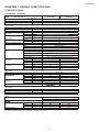
[1] SPECIFICATION
1. AY-ZP35PR – AE-Z35PR
MODEL
ITEMS
Rated cooling capacity (Min. – Max.)
Rated heating capacity (Min. –Max.)
Moisture removal (at cooling)
Electrical data
Phase
Rated frequency
Rated voltage
Rated current 䃩
(Min - Max.)
Rated input 䃩
(Min - Max.)
Power factor 䃩
Maximum operating current
Compressor
Refrigerant system
Cooling
Heating
Cooling
Heating
Cooling
Heating
INDOOR UNIT
AY-ZP35PR
kW
kW
Liters/h
2.5 (1.3 - 3.0)
3.2 (0.9 - 5.0)
0.8
Single
50
220-240
3.2 (1.8 - 4.3 )
3.7( 1.3 - 6.7 )
620 (340- 830)
750 (260 - 1360)
84
88
8.1
Hermetically sealed rotary type
5RS102XBE01
320cc (RB68A)
Louver Fin and Grooved tube type
Corrugate Fin and Grooved tube type
Hz
V
A
A
W
W
%
%
A
Type
Model
Oil Charge
Evaporator
Condenser
Control
Expansion valve
Refrigerant (R410A)
De-lce system
Noise level
(at cooling)
Noise level
(at heating)
990g
Micro computer controled reversed systems
High
Low
Soft
High
Low
Soft
dB(A)
dB(A)
dB(A)
dB(A)
dB(A)
dB(A)
High
Low
Soft
High
Low
Soft
m3/min.
m3/min.
m3/min.
m3/min.
m3/min.
m3/min.
42
36
30
43
40
36
Fan system
Drive
(at cooling)
(at heating)
OUTDOOR UNIT
AE-Z35PR
45
46
-
Direct drive
11.2
8.7
6.9
28.3
-
Fan
Propeller fan
Connections
Refrigerant coupling
Refrigerant tube size (Gas, Liquid)
Drain piping
inch
mm
Flare type
3/8", 1/4"
mm
mm
mm
kg
Fan motors : Thermal fuse
Fuse, Micro computer control
Polypropylene net (Washable)
860
780
292
540
205
265
9
34
Others
Safety device
Net dimensions
Net/Gross weight
Width
Height
Depth
NOTE:The conditions of star “ 䃩 ” marked item are based on “EN14511”.
1-1
AY-ZP35PR
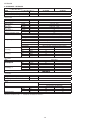
2. AY-ZP40PR – AE-Z40PR
MODEL
ITEMS
Rated cooling capacity (Min. – Max.)
Rated heating capacity (Min. –Max.)
Moisture removal (at cooling)
Electrical data
Phase
Rated frequency
Rated voltage
Rated current 䃩
(Min - Max.)
Rated input 䃩
(Min - Max.)
Power factor 䃩
Maximum operating current
Compressor
Refrigerant system
Cooling
Heating
Cooling
Heating
Cooling
Heating
INDOOR UNIT
AY-ZP40PR
kW
kW
Liters/h
3.5 (1.3 - 4.0)
4.0 (0.9 - 6.0)
1.2
Single
50
220-240
4.8 ( 1.8 - 6.5 )
4.8 ( 1.3 - 8.5 )
1000 (340 - 1350)
1020 (260 - 1800)
91
92
9.3
Hermetically sealed rotary type
5RS102XBE01
320cc (RB68A)
Louver Fin and Grooved tube type
Corrugate Fin and Grooved tube type
Hz
V
A
A
W
W
%
%
A
Type
Model
Oil Charge
Evaporator
Condenser
Control
Expansion valve
Refrigerant (R410A)
De-lce system
Noise level
(at cooling)
Noise level
(at heating)
990g
Micro computer controled reversed systems
High
Low
Soft
High
Low
Soft
dB(A)
dB(A)
dB(A)
dB(A)
dB(A)
dB(A)
High
Low
Soft
High
Low
Soft
m3/min.
m3/min.
m3/min.
m3/min.
m3/min.
m3/min.
44
35
30
45
40
35
Fan system
Drive
(at cooling)
(at heating)
OUTDOOR UNIT
AE-Z40PR
47
48
-
Direct drive
12.3
8.7
6.9
32.5
-
Fan
Propeller fan
Connections
Refrigerant coupling
Refrigerant tube size (Gas, Liquid)
Drain piping
inch
mm
Flare type
3/8", 1/4"
mm
mm
mm
kg
Fan motors : Thermal fuse
Fuse, Micro computer control
Polypropylene net (Washable)
860
780
292
540
205
265
9
34
Others
Safety device
Net dimensions
Net/Gross weight
Width
Height
Depth
NOTE:The conditions of star “ 䃩 ” marked item are based on “EN14511”.
1-2
AY-ZP35PR
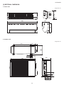
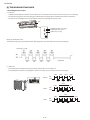
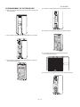
[2] EXTERNAL DIMENSION
1. Indoor unit
Length unit: mm
18.5
175
58
22.0
205
292
860
2. Outdoor unit
Length unit: mm
135
72
299
324
540
12
37.5
58
14
265
81
136
540
780
165
167.5
1-3
AY-ZP35PR
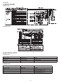
[3] WIRING DIAGRM
1. Indoor unit
2 Outdoor Unit
[4] ELECTRICAL PARTS
1. Indoor unit
DESCRIPTION
Indoor fan motor
Indoor fan motor capacitor
Transformer
FUSE1
MODEL
SFN-230-22-4F-1
A155BLS1S40D
VRK4119-290mA
-
REMARKS
AC Motor
RTRNPA030JBZZ
QFS-IA002JBZZ (250V, 2.5A)
MODEL
5RS102XBE01
ARW84038H
-
REMARKS
DC Motor
DC Motor
QFS-GA077JBZZ(250V, 2A)
QFS-GA078JBZZ(250V, 3.15A)
QFS-GA001JBZZ(250V, 20A)
QFS-GA002JBZZ(250V, 15A)
2 Outdoor Unit
DESCRIPTION
Compressor
Outdoor fan motor
Fu3
Fu2
Fu1
Fu5
1-4
AY-ZP35PR
CHAPTER 2. EXPLAMATION OF CIRCUIT AND OPERATION
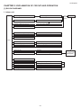
[1] BLOCK DIAGRAMS
1. Indoor unit
5VDC regulation
12V DC regulation
AC power
2.5A
Fuse
Fan motor phase control circuit
Indoor fan motor
Rotation pulse input circuit
Fan motor pulse detect
AC clock circuit
Remote controller signal reception circuit
Wireless remote control operation
Buzzer drive circuit
Audible operation confirmation
CPU reset circuit
CPU
Room temp. detect circuit
Room temp. thermistor
Heat exchanger pipe thermo circuit
Heat exchanger pipe thermistor
EEPROM
Louvre angle, fan speed
Select circuit
Wireless
Serial I/O circuit
Indoor/outdoor control signal I/O
Auto restart circuit
Test run circuit
Test run (forced operation)
Auxiliary mode
Auxiliary mode button ON/OFF
Power on circuit
Self diagnostics, fault diagnosis
Cluster generator drive circuit
Cluster generator
2-1
Unit-unit wiring
(AC power and
serial signals)
AY-ZP35PR
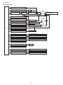
2. Outdoor unit
AC clock circuit
Pulse amplitube modulation circuit
IGBT
Power supply circuit
Power factor
converter circuit
Smoothing
circuit
Filter
circuit
20A
protection
CPU oscillator circuit
3.15A
protection
DC overvoltage detection circuit
Outdoor fan drive circuit
Outdoor fan
4-way valve relay drive circuit
4-way valve
15A
protection
DC overcurrent detection circuit
Power transistor module drive circuit
CPU
Power transistor module
Serial I/O circuit
CPU reset circuit
Position detection circuit
Compressor
AC overcurrent detection circuit
Current transformer
Compressor thermo circuit
Compressor thermistor
Heat exchanger pipe thermo circuit
Heat exchanger pipe thermistor
Outdoor temp. thermo. circuit
Outdoor temperature thermistor
EEPROM
LED drive circuit
LED
Test mode circuit
Expansion valve drive circuit
Expansion valve
Suction temp. thermo. circuit
Suction pipe thermistor
2-way valve temp. thermo. circuit
2-way valve thermistor
2-2
Unit-unit wiring (AC power
and serial signals)
AY-ZP35PR
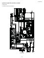
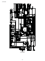
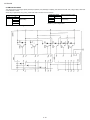
[2] MICROCOMPUTER CONTROL SYSTEM
1. Indoor unit
1.1. Electronic control circuit diagram
AY-ZP35PR
2-3
AY-ZP35PR
AY-ZP40PR
2-4
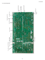
CN10
terminal fuse
CN1
fan motor
CN6
PCI
CN3
stepping motor
of ver cal
CN5
feedback of fan motor
CN4
stepping motor
of horizontal
CN2
thermistor
CN7
display board
AY-ZP35PR
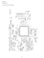
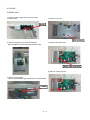
1.2. Printed wiring board
2-5
AY-ZP35PR
2. Outdoor unit
2.1. Electronic control circuit diagram
2-6
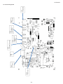
㼀㼛㻌㻾㼑㼍㼏㼠㼛㼞㻔㻳㼞㼍㼥㻕
㻲㼞㼛㼙㻌㻯㼛㼙㼜㼞㼑㼟㼟㼛㼞㻌㻔㻯㻕㻔㼃㻕㻔㻻㼞㼍㼚㼓㼑㻕
㻲㼞㼛㼙㻌㻯㼛㼙㼜㼞㼑㼟㼟㼛㼞 (R)(V)(White)
㻲㼞㼛㼙㻌㻯㼛㼙㼜㼞㼑㼟㼟㼛㼞㻌㻔㻿㻕㻔㼁㻕㻌㻔㻾㼑㼐㻕
㻲㼞㼛㼙㻌㻲㼍㼚㻌㻹㼛㼠㼛㼞
㻲㼞㼛㼙㻌㼀㼔㼑㼞㼙㼕㼟㼠㼛㼞
2-7
㼀㼛㻌㼀㼑㼞㼙㼕㼚㼍㼘㻌㻮㼛㼍㼞㼐㻔㻺㻕
㻌㻔㻮㼘㼡㼑㻕
㼀㼛㻌㻯㼛㼚㼠㼞㼛㼘㻌㻮㼛㼤
㻔㻳㼞㼑㼑㼚㻛㼅㼑㼘㼘㼛㼣㻕
㼀㼛㻌㼀㼑㼞㼙㼕㼚㼍㼘㻌㻮㼛㼍㼞㼐㻔㻞㻕
㻌㻔㻾㼑㼐㻕
㼀㼛㻌㼀㼑㼞㼙㼕㼚㼍㼘㻌㻮㼛㼍㼞㼐㻔㻝㻕
㻌㻔㻮㼞㼛㼣㼚㻕
㻲㼞㼛㼙㻌㻠㼃㼍㼥㻌㼂㼍㼘㼢㼑
㻲㼞㼛㼙㻌㻱㼤㼜㼍㼚㼟㼕㼛㼚㻌㼂㼍㼘㼢㼑
AY-ZP35PR
2.1. Printed wiring board
AY-ZP35PR
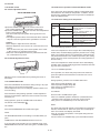
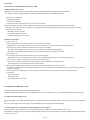
[3] FUNCTION
1.6. Indoor unit overheat prevention control
1. Function
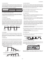
1.1. Startup control
The main relay remains off during the first 45 seconds (first
safety time) immediately after the power cord is plugged into an
AC outlet inorder to disable outdoor unit operation and protect
outdoor unit electric components.
1.2. Restart control
Once the compressor stops operating, it will not restart for 180
seconds to protect the compressor.
Therefore, if the operating compressor is shut down from the
remote control and then turned back on immediately after, the
compressor will restart after a preset delay time.
(The indoor unit will restart operation immediately after the ON
switch is operated on the remote control.)
Compressor operation
Compressor ON
Compressor remains OFF
for 180 seconds
OFF operation on
remote control
ON operation on
remote control
During heating operation, if the temperature of the indoor unit
heat exchanger exceeds the indoor unit heat exchanger overheat
prevention temperature (about 45 to 54 Υ ) which is determined
by the operating frequency and operating status, the operating
frequency is decreased by about 4 to 15 Hz. Then, this operation
is repeated every 60 seconds until the temperature of the
indoor unit heat exchanger drops below the overheat protection
temperature.
Once the temperature of the indoor unit heat exchanger drops
below the overheat protection temperature, the operating
frequency is increased by about 4 to 10 Hz every 60 seconds until
the normal operation condition resumes.
If the temperature of the indoor unit heat exchanger exceeds
the overheat protection temperature for 60 seconds at minimum
operating frequency, the compressor stops operating and then
restarts after about 180 seconds, and the above mentioned
control is repeated.
1.7. Outdoor unit overheat prevention control
Compressor can
turn ON
During cooling operation, if the temperature of the outdoor
unit heat exchanger exceeds the outdoor unit heat exchanger
overheat prevention temperature (about 55 Υ ), the operating
frequency is decreased by about 4 to 15 Hz. Then, this operation
is repeated every 60 seconds until the temperature of the outdoor
unit heat exchanger drops to about 54 Υor lower.
Compressor ON
1.3. Cold air prevention control
When the air conditioner starts up in heating mode, the indoor
unit fan will not operate until the temperature of the indoor unit
heat exchanger reaches about 23°C in order to prevent cold air
from blowing into the room.
Also, the indoor unit fan operates at low speed until the
temperature of the indoor unit heat exchanger reaches about
!#$&$'&*+!&;<=*''+>&&'?!*''@#*;\=
Indoor unit heat exchanger temperature
Set fan speed
Once the temperature of the outdoor unit heat exchanger drops
to about 54 Υ or lower, the operating frequency is increased by
about 4 to 10 Hz every 60 seconds until the normal operation
condition resumes.
If the temperature of the outdoor unit heat exchanger exceeds
the outdoor unit heat exchanger overheat protection temperature
>;&?^_`;&<$&;#_;&{ Υ ; 60 sec : outdoor
temperature < 40 Υ ) at minimum operating frequency, the
compressor stops operating and then restarts after about 180
seconds, and the above mentioned control is repeated.
1.8. Compressor overheat prevention control
38Υ
35Υ
If the temperature of the compressor exceeds the compressor
overheat prevention temperature (110Υ ), the operation frequency
isdecreased by about 4 to 10 Hz. Then, this operation is repeated
every 60 seconds until the temperature of the compressor drops
below theoverheat protection temperature (100Υ ).
Indoor unit fan at Ultra soft.
(Lower than Fan speed "soft")
23Υ
21Υ
Indoor unit fan in non-operation
1.4. Indoor unit heat exchanger freeze prevention control
If the temperature of the indoor unit heat exchanger remains
below 0 Υ for 4 consecutive minutes during cooling or
dehumidifying operation, the compressor operation stops
temporarily in order to prevent freezing.
Once the temperature of the compressor drops below the
overheat protection temperature, the operating frequency is
increased by about 4 to 10 Hz every 60 seconds until the normal
operation condition resumes.
When the temperature of the indoor unit heat exchanger rises to
2 Υ or higher after about 180 seconds, the compressor restarts
and resumes normal operation.
If the temperature of the compressor exceeds the overheat
protection temperature (for 120 seconds in cooling operation or
60 seconds in heating operation) at minimum operating frequency,
the compressor stops operating and then restarts after about 180
seconds, and the above mentioned control is repeated.
1.5. Outdoor unit 2-way valve freeze prevention control
1.9. Startup control
If the temperature of the outdoor unit 2-way valve remains below
0 Υ for 10 consecutive minutes during cooling or dehumidifying
operation, the compressor operation stops temporarily in order to
prevent freezing.
When the air conditioner starts in the cooling or heating mode, if
the room temperature is 2 Υ higher than the set temperature (in
cooling operation) or 3.5 Υ lower(in heating operation), the air/
air heat pump operateswith the operating frequency at maximum.
Then, when the set temperatureis reached, the air/air heat pump
operates at the operating frequencydetermined by fuzzy logic
calculation, then enters the normal control mode after a while.
When the temperature of the 2-way valve rises to 10Υ or higher
after about 180 seconds, the compressor restarts and resumes
normal operation.
2-8
AY-ZP35PR
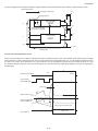
1.10. Peak control
1.15. Power ON start
If thecurrent flowingin the air/air heat pump exceeds the peak
control current (see the table below), the operation frequency is
decreased until the current value drops below the peak control
current regardless of the frequency control demand issued from
the indoor unit based on the room temperature.
If a jumper cable is inserted in the location marked with HAJP
on the indoor unit control printed circuit board (control PCB),
connecting the power cord to an AC outlet starts the air/air heat
pump in either cooling or heating mode, which is determined
automatically by the room temperature sensor.
Model
Peak control current
Cooling operation Heating operation
Approx. 7.1A
Approx. 8.1A
Approx. 8.1A
Approx. 9.3A
AE-Z35PR
AE-Z40PR
When a circuit breaker is used to control the ON/OFF operation,
please insert a jumper as described above.
1.16. Self-diagnostic malfunction code display
1.11. Outdoor unit fan delay control
1.16.1 Indoor unit
The compressor stops immediately after cooling, dehumidifying or
heating operation is shut down, but the outdoor unit fan continues
operation for 50 seconds before it stops.
1)When a malfunction is confirmed, all relays turn off and a
flashing operation LED.timer LED.Plasamacluter LED is
displayed to indicate the type of malfunction.
1.12. Defrosting
When the air/air heat pump is in non-operating condition,
holding down AUX button for more than 5 seconds activates the
malfunction code display function.
1.12.1 Reverse defrosting
The defrost operation starts when the compressor operating
time exceeds 20 minutes during heating operation, as shown
below, and the outside air temperature and the outdoor unit heat
exchanger temperature meet certain conditions. When the defrost
operation starts, the indoor unit fan stops. The defrost operation
stops when the outdoor unit heat exchanger temperature rises to
about 10°C or higher or the defrosting time exceeds 10 minutes.
20 min or more
Start of
heating
operation
20 min or more
Defrosting
Max. 10 min
The operation continues only in the case of a serial
opencircuit,and the main relay turns off after 30 seconds if the
open-circuit condition remains.In the case of a serial shortcircuit, the air/air heat pump continues operating without a
malfunction code display, and the main relay turns off after 30
seconds if the short-circuit condition remains.
20 min or more
The malfunction information is stored in memory, and can be
recalled later and shown on display.
2)The self-diagnostic memory can be recalled and shown on the
display by stopping the operation and holding down AUX button
for more than 5 seconds.
(For details, refer to the troubleshooting section.)
Defrosting
Max. 10 min
1.13. ON timer
1.16.2 Outdoor unit
The ON timer can be activated by pressing the ON timer button.
When the ON timer is activated, the operation start time is
adjusted based on fuzzy logic calculations 1 hour before the set
time so that the room temperature reaches the set temperature at
the set time.
If a malfunction occurs, LED1 on the outdoor unit flashes in
0.2-second intervals as shown below.
(Example) Compressor high temperature abnormality
ON
1.14. OFF timer
OFF
The OFF timer can be activated by pressing the OFF timer button.
When the OFF timer is set, the operation stops after the set time.
When this timer is set, the compressor operating frequency lowers
for quieter operation, and the room temperature is gradually
varied after one hour (reduced 1°C three times (max. 3°C) in
heating, or increased 0.3°C three times (max. 1°C) in cooling or
dehumidifying operation) so that the room temperature remains
suitable for comfortable sleeping.
1 sec 1 sec 0.6 sec
1.17. Information about auto mode
In the AUTO mode, the temperature setting and mode are
automatically selected according to the room temperature and
outdoor temperature when the unit is turned on.
Modes and Temperature Settings
Heating operation
Set temperature
O
-1 C
O
-1 C
O
-1 C
Activation of
OFF timer
1 hour
later
Max.
Max.
Timer setting
1.5 hours 2 hours reached
later
later
Cooling/dehumidifying operation
O
O
Set temperature
Activation of
OFF timer
0.3 C
0.3 C
1 hour
later
the figures in ( ) are temperature settings
During operation, if the outdoor temperature changes, the
temperature settings will automatically slide as shown in the chart.
O
0.3 C
Max.
Timer setting
Max.
1.5 hours 2 hours reached
later
later
2-9
AY-ZP35PR
For vertical adjustment louvre:
1.20. Difference of operation in Auto and Manual modes
In the Auto mode, the temperature setting is automatically determined based on the outside air temperature. In addition, the air/
air heat pump operation differs from the operation in the Manual
mode as explained below.
AIR FLOW DIRECTION
1.21. Difference relating to set temperature
Temperature setting method
1)Press the SWING button( ) on the remote control once. ~!&&;*?#'#`_<&+'_;&=*''=*+?+*+__'@
2)Press the SWING button( ) again when the vertical adjustment
louvre is at the desired position.
~!&'_;&=*''$<*+=*!*+!&;#+&!=+*+!&
diagram.
~!&#`_&`$**+=*''&<&<;*&`#+`=*''&#_<#*cally set to the same position when operated the next time.
Caution:
Never attempt to adjust the louvres manually.
~
#+_#'#`_<&++!&'_;&?#+?#_&!&_+*<#'function.
Also, the louvre may stay in the closed position in the COOL
or DRY mode for an extended period of time.
~!&+!&&;*?#'#`_<&+'_;&*$**+&`#!&'=est, condensation may result.
For horizontal adjustment louvres:
A u t o Cooling
mode
Heating
Dehumidifying
M a n u a l Cooling
mode
Heating
Dehumidifying
Automatic temperature
setting based on outside air
temperature.
Can be changed within ±2 Υ
using remote control.
Can be changed between 18
and 32Υ using remote control.
Can be changed between 18
and 32Υ using remote control.
Automatic setting.
Can be changed within ±2Υ .
1.22. Dehumidifying operation control
If the room temperature is 26Υ or higher when dehumidifying operation starts, the dehumidifying operation provides a low cooling
effect in accordance with the room temperature setting automatically determined based on the outside air operation. (The setting
value is the same as the set temperature for cooling operation in
the auto mode.)
If the room temperature is lower than 26Υ when dehumidifying
operation starts, the dehumidifying operation minimizes the lowering of the room temperature.
1.23. FULL POWER Operation
Lever
Adjust the louvre to desired direction by holding the levers on
louver links
In this operation, the air/air heat pump works at the maximum
power and optimum louvre direction to make the room cool or
warm rapidly.
During operation, press the FULL POWER button.and
1.19. COANDA AIR FLOW
Press the COANDA AIR FLOW button during cooling or dry operation when you do not want to feel cold air.
Vertical adjustment louvre is set obliquely upward to deliver cool
air to the ceiling.
~!&;&<&?+;'=*''`*$'#@ ".
~!&&<$&;#_;&`*$'#@=*''>>
~!&;&&+'#<$+
~!&_+*=*'''*!_$
TO CANCEL
Press the button during heating operation. Vertical adjustment
'_;&*&`=+=#;``&'*&;!&=#;<#*;`=+!&\;
and warm you.
During operation, press the COANDA AIR FLOW button.
The remote control will display” ”.
Press the FULL POWER button again.
~!&$&;#*+=*''#'&?#+?&''&`=!&+!&
operation mode is changed, or when the unit is turned off.
~!&;&&+'#<$+!&_+*=*''_;+>>
NOTE:
TO CANCEL
Press the PROGRESSIVE AIR FLOW button again.
NOTE:
The PROGRESSIVE AIR FLOW setting is cancelled When you
press
TURBO button while PROGRESSIVE AIR FLOW is set.
The air/air heat pump will operate at “Extra HIGH” fan speed for 5
minutes, and then shift to “HIGH” fan speed. The vertical adjustment louvre will be set obliquely downward.
~_?#++&!&&<$&;#_;&;>#+$&&``_;*+!&
POWER operation.
~_;+>>!&'#<$$;&!&_+
If you want AIR FLOW operation in FULL POWER mode, press
PROGRESSIVE AIR FLOW button during FULL POWER operation.
2-10
AY-ZP35PR
1.24. Self Clean operation
O
0.6 C
Heating or Fan operation and Cluster operation are performed
simultaneously.
Hot keep zone
Set temperature
The judgment of whether Heating or Fan operation is used is
based on the outside air temperature at 3 minutes after the start
of internal cleaning.
The operation stops after 40 minutes.
1.28. Winter cool
Cooling operation is available during the winter season by the
built in winter cool function.
Lower limit of outdoor temperature range is -10°C DB.
When the outside air temperature is low, the outdoor unit fan
operates at slower speed.
_;*+!*$&;#*+!&!;*+#''_&;<&#+`#@=
positions.
It turns to the lower direction and stays for 30 minutes.
NOTE:
Built-in protect device may work when outdoor temperature falls
below 21°C DB., depending on conditions.
Next moves upward and stays for 10 minutes.
Heating operation
Fan operation
1.29. Auto restart
O
24 C
Outside air temperature
When power failure occurs, after power is recovered, the unit will
automatically restart in the same setting which were active before
the power failure.
1.25. Plasmacluster Ion function
Operating the Plasmacluster Ion button while the air conditioner is
in operation or in non-operation allows the switching of the op&;#*+<`&*+!&>''=*+&_&+?&^*;'&#+$&;#*+
“Stop”.
*;'&#+$&;#*+&+&;#&#_&_#'#<_+>*+
and (-)ions from the cluster unit to provide clean air.
1.29.1 Operating mode (Cool, Heat, Dry)
&<$&;#_;&#`_<&+=*!*+;#+&#_<#*?$&;#*+
&<$&;#_;&&*+
#+&*+
If the Plasmacluster Ion generation function is operated together
with the air conditioner operation, the indoor unit fan speed and
louver direction are in accordance with the air conditioner settings.
*;\=`*;&?*+
If the Plasmacluster Ion generation function is used without operating the air conditioning function, the indoor unit fan operates at
a very low speed and the upper louver is angled upward and the
'=&;'_&;;&<#*+!;*+#'!&#*;\='_<&#+``*;&?*+
can be changed by using the remote control.)
'#<#?'_&;<`&
=&;
_<#*?$&;#*+<`&&*+
=*+'_;&
1.29.2 Setting not memorized
*<&;&*+
_;$&;#*+&*+
1.26. 10°C OPERATION
&'>?'&#+$&;#*+
Heating operation with 10°C set temperature will be performed.
1.30 Heat only mode.
1)Press the MODE button of Remote controller and select HEAT
mode.
2)Press the ON / OFF button to start HEAT operation.
3)Press the 10°C button.
!&;&<&?+;'=*''`*$'#@
When heat only mode, cut the JPW jumper
cool heat mode
heat only mode
JPW connected
JPW cut
TO CANCEL
Press the 10°C button again.
$&;#*+=*''#'&?#+?&''&`=!&+!&$&;#*+<`&
is changed, or when the unit is turned off.
NOTE:
$&;#*+=*''+&##*'#'&=*!!&#*+$&;#*+#_matically selected by AUTO mode.
ZONE
Hot keep (When
room temperature
reaches setting
temperature)
COMPRESSOR
OFF
JPW
1.27. Hot keep
If the room temperature is in the Hot keep zone during heating,
the compressor is turned off to prevent overheating.
FAN
Ultra soft (Lower
than Fan speed
“soft”)
2-11
AY-ZP35PR
2. Explanation of cluster circuit
!&?'_&;_+*&+&;#&?'_&;*+=!*?!#;&?*;?_'#&`!;_!_!&;<@!&#;*\=?;&#&`@!&'=&;>#+*+`;_+*
fan) in the air/air heat pump unit.
When microcomputer output turns "H", the Q11 output changes to "Lo", turning ON the cluster unit for the generation of cluster ions
(positive and negative ions).
Cluster unit
12V
Q11
Microcomputer output
R39
1
1
3
3
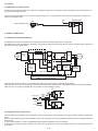
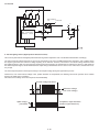
3. Outline of PAM circuit
3.1. PAM (Pulse Amplitude Modulation)
The PAM circuit varies the compressor drive voltage and controls the rotation speed of the compressor.
The IGBT shown in the block diagram charges the energy (electromotive force) generated by the reactor to the electrolytic capacitor for
the inverter by turning ON and OFF.
Reactor L5
DB1
AC
230V
Noise
filter
+
IPM
Compressor
DB2
IGBT
drive
circuit
AC clock
detection
circuit
Overvoltage
detection
circuit
IGBT
Compressor
position
detector
[PAM drive circuit]
Microcomputer (IC1)
PAM drive circuit block diagram
!&+!&*#+&'&?;*??_;;&+\=!&*#!&;&#?;
#+``*`&;*`&
When the IGBT turns OFF, the energy stored while the IGBT was ON is charged to the voltage doubler capacitor via the diode bridge
(DB1).As such, by varying the ON/OFF duty of the IGBT, the output voltage is varied.
DB1
Reactor
Stored energy
L5
L6
DB2
IGBT ON
IGBT OFF
IGBT
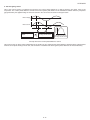
3.2. High power factor control circuit
This circuit brings the operating current waveform closer to the waveform of commercial power supply voltage to maintain a high power
factor.
Because of the capacitor input, when the PAM circuit is OFF, the phase of the current waveform deviates from the voltage waveform as
shown below.
To prevent this deviation, a current is supplied during the periods indicated by "O" in the diagram.
To determine the length of period to supply a current, the zero-cross timing of the AC input voltage is input to the microcomputer via the
clock circuit.
2-12
AY-ZP35PR
The power source frequency is also determined at the same time.
The IGBT turns ON after the time length determined by the zero-cross point to supply a current to the IGBT via the reactor.
This brings the current waveform closer to the voltage waveform in phase.
As described above, the ON/OFF operation of the IGBT controls the increase/decrease of the compressor power supply voltage (DC
voltage ) to improve the compressor efficiency and maintain a high powerfactor by keeping the current phase closer to that of the supply
voltage.
AC voltage waveform
AC voltage waveform
AC current waveform
AC current waveform
Zero-cross detection
IGBT ON period
AC voltage and current waveforms when PAM is OFF
AC voltage and current waveform when PAM is ON
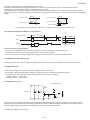
3.2.1 Detailed explanation of PAM drive circuit sequence
AC voltage waveform
Clock
A
B
A
C
IGBT ON
B
50Hz
1.2mS
1.2mS
0.25 2.3mS
C
3.2.2 AC clock (zero-cross) judgment
The clock circuit determines the time from one rising point of the clock waveform to the next rising point.
The detected clock waveform is used to judge the power source frequency (50Hz).
The zero-cross of the AC voltage is judged as the rising of the clock waveform, as shown in the diagram above.
3.2.3 IGBT ON start time (delay time B)
#&`+!&&;?;>!& AC voltage, the IGBT turns ON after a delay time set according to the power source frequency.
3.2.4 IGBT ON time (C)
After the above delay time, the IGBT turns ON to supply a current to the reactor.
The ON time of the IGBT determines the amount of energy (level of DC voltage rise) supplied to the reactor.
DC voltage level in each operation mode (varies depending on external load conditions)
–Cooling operation --- 260 to 280 V
–Heating operation --- 260 to 290 V
3.3. PAM protection circuit
(Overvoltage detection)
R125
270K Ω
1/2W
F
DC Voltage
C9
550uF
400V
C10
550uF
400V
5V
R126
270K Ω
1/2W
F
R127
13K Ω
D19
IC1
R128
13K Ω
C87
50V
69
0V
To prevent excessive voltage of PAM output from damaging the IPM and electrolytic capacitor as well as the control printed circuit
board (PCB), this circuit monitors the PAM output voltage and turns off the PAM control signal and PAM drive immediately when an
abnormal voltage output is generated. At the same time, it shuts off the compressor operation.
The protection voltage level is as follows.
2-13
AY-ZP35PR
3.3.1 Details of troubleshooting procedure for PAM
1) PAM shutdown due to error
!&+!&'#&`&&?*+?*;?_*&+`#*+#'&?&&`*+!&$&?*&`'#&!&<*?;?<$_&;
DC voltage of 350 V or higher (detection circuit input voltage of about 9.2 V or higher) [IC8 pin (4)]
–When an error is detected
_;+
<$;&;_;+
''_+*!_`=+?<$'&&'@=!&+!&&;;;??_;>_;*<&
!&+!&_`;_+*?'?=#&>;<`*>>&;>;<!&$&?*&`#'_&*<<&`*#&'@&>;&!&
_;+
!&+!&;&*+?'?=#&>;<*+$_!&+#?'?*+#'>!&;!#+$&?*&`$=&;_;?&>;&_&+?@
**+$_
–When an error is detected
`&+_;+
<$;&;$&;#&+;<#''@
<$'&&!_`=+`&+??_;
2) PAM error indication
In case of error “1)”
– An error signal is sent to the indoor unit as soon as an error is generated.
#'>_+?*+**+`*?#&`=!&+!&&;;;?`&*?#''&`_@!&*+`;_+* &'>`*#+*>_+?*+
¡!&+!&_`;_+*\#!&*<&=!&+#+&;;;*&+&;#&`
!&?+*+_&\#!*+*+!&*<&?@?'&&&+#>&;!&?<$;&;$$&;#*+
!&_;+>>`##*`&'&&`>;<!&<&<;@=!&+!&_`;_+*$=&;*_;+&`>>
In case of error “2)”
– An error signal is sent to the indoor unit as soon as an error is judged.
#'>_+?*+**+`*?#&`=!&+!&&;;;?`&*?#''&`_@!&*+`;_+* &'>`*#+*>_+?*+
¡!&+!&_`;_+*\#!&*<&=!&+#+&;;;*_`&`
!&+!&_`;_+*\#!&*++;<#'$#&;+=!&+!&?<$;&;$$&;#*+
(Compressor OFF or Thermostat OFF from remote control)
¢!&+#_&;?<$'#*+!#!&#*;#*;!&#$_<$`&+$;*`&_>?*&+?'#*;;=#;<#*;
In addition to conventional error-generating reasons, there is a possibility that the PAM IGBT does not turn ON even if the compressor is operating.
In that case, the DC voltage does not rise even though the compressor is operating, and lowers to the 180-VDC level.
–Check items
'??*;?_*?!&?
?!&?
_&_$&+?*;?_*?!&?
4. Explanation of IPM drive circuit
The IPM for compressor drive is made by Mitsubishi Electric.
The power supply for the IPM drive, the shunt resistance for over current detection, etc., are provided outside the IPM (control PCB).
4.1. IPM drive power supply circuit
The power supply for the upper-phase IGBT (HU, HV, HW) drive employs a bootstrap system, and provides power to the upper-phase
IC.
The 15-V power supply for the lower-phase IC is provided by the control printed circuit board (PCB).
4.1.1 Brief explanation of bootstrap system (single power drive system)
To supply power to the upper-phase IC, the microcomputer (IC1) turns ON the lower-phase IGBT (LU, LV, LW).
!*;&_'*+#?!#;*+?_;;&+!#\=!&&'&?;'@*??#$#?*;>&#?!_$$&;$!#&*+$_#+`?!#;&!&;#$?#$#?*tor with a 15V current.
2-14
AY-ZP35PR
The power supply for the subsequent stages is charged while the lower-phase IGBT is ON in ordinary compressor drive control.
Initial charge period
Charging current group
P(Vcc)
Bootstrap capacitor
(HU,HV,HW)
HVIC
VDB
U,V,W,
High-voltage-withstanding,
high-speed recovery diode
N-side
IGBT
(LU,LV,LW)
VD
LVIC
VCIN(n)
N(GND
Bootstrap circuit
4.1.2 DC over current detection circuit
!&+#?_;;&+>#_
;!*!&;\=!;_!!&!_+;&*#+?&£+!&?+;'$;*+&`?*;?_*#;`!&'#&
at this resistance is input to IPM CIN pin (26). Then, the gate voltage of the lower-phase IGBT (LU, LV, LW) inside the IPM turns OFF to
cut off the over current. At the same time, an L output of about 1.8 ms is generated from IPM Fo pin (24), and this results in an L input
to overcurrent detection input pin (34) of the microcomputer (IC1) and turns OFF the PWM signal output (IC1 pins (51) through (56)) to
the IGBT gate.
SET
Protection circuit status
RESET
(Lower phase)
Internal IGBT gate
(About 25 A)
SC
a1
Output current Ic (A)
SC reference voltage
Sense voltage relative
to shunt resistance
Delay by CR time constant circuit
About 1.8 ms
Error output Fo
2-15
AY-ZP35PR
P
Shunt resistance
Overcurrent
R49
N
5V
IC1
34
IPM overcurrent
detection circuit
CiN
26
FO
0V
24
51
56
5. 120° Energizing control (digital position detection control)
This control system detects the digital position detection signal and adjusts the rate of acceleration/deceleration accordingly.
!&<; *+`_?&`'#&=#&>;<**+$_!&?<$#;#;*+!&>;<>
=*?!&`$_'&=#&>;<#+`#$**+`&&?tion signal is generated as a reference voltage equaling 1/2 of 280 VDC. However, since there is no induced voltage waveform when
the PWM waveform is OFF, the microcomputer performs internal processing so that detection is enabled only when it is ON. Based on
!&`&&?&`$**+*+#'#?_#'
=#&>;<_$_*<*+*`&&;<*+&`*+?&*`&+_&#'&;?*;?_*!&`&&?*+#??_racy is high.
The microcomputer performs internal processing to cancel spike voltage during the regenerative process.
Furthermore, even if the induced voltage is low, position detection is still possible, thus allowing sensor-less operation at low rotation
speed in the initial stage of operation.
This reduces the starting current and improves the IPM reliability.
Terminal voltage waveform
Reference voltage
(1/2 of DC voltage)
Spike voltage
(cancelled)
Comparator output waveform
(Position signal waveform)
2-16
AY-ZP35PR
6. 180° Energizing control
This is the control system to moderate the speed by the current phase difference for higher efficiency and lower noise of the
?<$;&;!&?_;;&+$!#&`*>>&;&+?&?+;'*!&?+;'@&<$#*`#&+*+!&*+&;;&'#*+&=&&+&>?*&+?@#+`$!#&
#$&+&;#&`@!&#$$'*&`'#&><;#+`?_;;&+*+!&?*'><;#!=+*+!&_;&&'=
Motor voltage
Efficiency
Motor current
Optinum power
factor
Phase difference between
the voltage and the current
Phase difference between
the voltage and the current
Concept chart of the current phase difference control
This control is the V/F drive system independent of the location of rotor, detecting the phase difference between driving voltage phase
#+`'*+&?_;;&+$!#&\=*+*+<;?*'#+`?+;'!&<`_'#*+;#&`##&!&$!#&`*>>&;&+?&#!&&&>?*&+?@
2-17
AY-ZP35PR
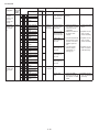
CHAPTER 3. FUNCTION AND OPERATION OF PROTECTIVE PROCEDURES
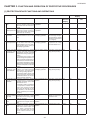
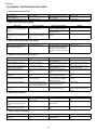
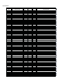
[1] PROTECTION DEVICE FUNCTIONS AND OPERATIONS
Function
Operation
Description
Detection period
Reset condition
Self-diagnosis result
display
Indoor
Indoor unit Outdoor
unit error
unit
display
When indoor unit fan is Operation OFF or ON
in operation
ۼ1
Yes
None
When indoor unit fan is Operation OFF or ON
in operation
ۼ1
Yes
None
When in cooling or de- Automatic reset when humidifying operation
heat exchanger temperature rises above freeze
prevention temperature
(2°C or higher)
3 2 - w a y v a l v e Compressor stops if tempera- When in cooling or de- Automatic reset when None
temperature of 2-way
freeze prevention ture of outdoor unit 2-way valve humidifying operation
valve rises above 10°C.
remains below 0°C for 10 continuous minutes during cooling or
dehumidifying operation.
None
None
Yes
Yes
4 Indoor unit heat Operating frequency lowers When in heating operaexchanger over- if indoor unit heat exchanger tion
heat shutdown
temperature exceeds overheat
temperature during heating operation.
Compressor stops if indoor unit
heat exchanger temperature exceeds overheat temperature for
60 seconds at minimum frequency.Overheat temperature setting
value indoor unit heat exchanger
thermistor temperature: about 45
to 54°C
5 Outdoor unit heat Operation frequency lowers if When in cooling or deexchanger over- outdoor unit heat exchanger humidifying operation
heat shutdown
temperature exceeds about
55°C during cooling operation.
Compressor stops if outdoor unit
heat exchanger temperature
exceeds about 55°C for 120 seconds at minimum frequency.
6 Compressor dis- Operating frequency lowers When compressor is in
charge overheat if temperature of compressor operation
shutdown
chamber thermistor (TH1) falls
below about 110°C.
Compressor stops if temperature
of compressor chamber thermistor (TH1) remains at about
110°C (for 120 seconds in cooling operation, or 60 seconds in
heating operation) at minimum
frequency.
7 D e h u m i d i f y i n g Compressor stops if outside air When in dehumidifying
operation tempo- temperature thermistor is lower operation
rary stop
than about 16°C during dehumidify-ing operation.
8 DC overcurrent Compressor stops if DC current When compressor is in
error
>#_
;!*!&;\=*+ operation
IPM.
9 AC overcurrent Operating frequency lowers if When compressor is in
error
outdoor AC current exceeds operation
peak control current value. outdoor stops if compressor AC
current exceeds peak control
current value at minimum frequency.
Automatic reset after None
safety period (180 sec).
Yes
Yes
Automatic reset after None
safety period (180 sec).
Yes
Yes
Automatic reset after None
safety period (180 sec).
Yes
Yes
Automatic reset when None
outside air temperature
rises above 16°C.
Yes
Yes
1 Indoor unit fan Operation stops if there is no
lock
input of rotation pulse signal
from indoor unit fan motor for 1
minute.
Indoor unit fan ro- Operation stops if rotation pulse
tation speed error signal from indoor unit fan indicates abnormally low speed
(about 300 rpm or slower).
2 Indoor unit freeze Compressor stops if temperature
prevention
remains below 0°C for 4 minutes.
3-1
Operation OFF or ON
Yes ۼ2
Yes
Yes
Operation OFF or ON
Yes ۼ2
Yes
Yes
AY-ZP35PR
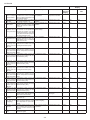
Function
Operation
Description
25 Compressor startup error
26 Compressor rotation error (at 120°
energizing)
27 Outdoor unit DC
fan error
28 PAM overvoltage
error
Reset condition
When compressor is in Replacement of defec- Yes ۼ1
non-operation
tive parts such as IPM
Yes
Yes
Yes ۼ2
Yes
Yes
Yes ۼ2
Yes
Yes
3 minutes after com- Operation OFF or ON
pressor startup
Yes ۼ2
Yes
Yes
When in operation
Operation OFF or ON
Yes ۼ2
Yes
Yes
At compressor startup
Operation OFF or ON
Yes ۼ2
Yes
Yes
At compressor startup
Operation OFF or ON
Yes ۼ2
Yes
Yes
At compressor startup
Operation OFF or ON
Yes ۼ2
Yes
Yes
Compressor stops if there is At compressor startup
short-circuit in outdoor unit 2-way
valve thermistor (TH5).
Operation OFF or ON
Yes ۼ2
Yes
Yes
Compressor stops if there is At compressor startup
open-circuit in outdoor unit heat
exchanger thermistor (TH2).
Operation OFF or ON
Yes ۼ2
Yes
Yes
Compressor stops if there is At compressor startup
open-circuit in outdoor unit outside air temperature thermistor
(TH3).
Compressor stops if there is At compressor startup
open-circuit in outdoor unit suction ther-mistor (TH4).
Compressor stops if there is At compressor startup
open-circuit in outdoor unit 2-way
valve thermistor (TH5).
Operation OFF or ON
Yes ۼ2
Yes
Yes
Operation OFF or ON
Yes ۼ2
Yes
Yes
Operation OFF or ON
Yes ۼ2
Yes
Yes
At compressor startup
Operation OFF or ON
Yes ۼ2
Yes
Yes
When in operation
Reset after reception of None
serial signal
None
None
At compressor startup
Operation OFF or ON
Yes ۼ3
Yes
Yes
Compressor operating Operation OFF or ON
at 120° energizing
Yes ۼ3
Yes
Yes
When outdoor unit fan is Operation OFF or ON
in operation
Yes ۼ2
Yes
Yes
When in operation
Yes ۼ2
Yes
Yes
10 AC overcurrent Indoor and outdoor units stop
error in compres- if outdoor AC current exceeds
sor OFF status
about 3 A while compressor is in
non-operation status.
11 AC maximum cur- Compressor stops if coutdoor
rent error
AC current exceeds 17 A.
12 AC current defi- Compressor stops if operating
ciency error
frequency is 50 Hz or higher and
outdoor AC current is about 2.0
A or lower.
13 T h e r m i s t o r i n - Compressor stops if high and
stallation error or low values of temperatures
4-way valve error detected by outdoor unit heat
exchanger thermistor (TH2) and
2-way valve thermistor (TH5) do
not match operating cycle.
14 Compressor high Compressor stops if compressor
temperature error chamber thermistor (TH1) exceeds about 114°C, or if there is
short-circuit in TH1.
15 Outdoor unit heat Compressor stops if there is
exchanger ther- short-circuit in outdoor unit heat
mistor short-cir- exchanger thermistor (TH2).
cuit error
16 Outdoor unit out- Compressor stops if there is
side air temper- short-circuit in outdoor unit outature thermistor side air temperature thermistor
short-circuit error (TH3).
17 Outdoor unit suc- Compressor stops if there is
t i o n t h e r m i s t o r short-circuit in outdoor unit sucshort-circuit error tion thermistor (TH4).
18 O u t d o o r u n i t
2-way valve thermistor short-circuit error
19 Outdoor unit heat
exchanger thermistor open-circuit error
20 Outdoor unit outside air temperature thermistor
open-circuit error
21 Outdoor unit suction thermistor
open-circuit error
22 O u t d o o r u n i t
2-way valve thermistor open-circuit error
23 Outdoor unit discharge thermistor
open-circuit error
24 Serial signal error
Detection period
Self-diagnosis result
display
Indoor
Indoor unit Outdoor
unit error
unit
display
Compressor stops if there is
open-circuit in outdoor unit discharge thermistor (TH1).
Compressor stops if outdoor unit
cannot receive serial signal from
indoor unit for 30 seconds.
Compressor stops if compressor
fails to start up.
Compressor stops if there is no
input of position detection signal
from compressor or input is abnormal.
Operation stops if there is no input of rotation pulse signal from
outdoor unit fan motor for 30
seconds.
Compressor stops if DC voltage
is 400 V or higher.
When compressor is in Operation OFF or ON
operation
When compressor is in Operation OFF or ON
operation
3-2
Operation OFF or ON
AY-ZP35PR
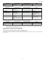
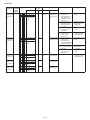
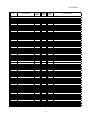
Function
Operation
Description
29 PAM clock error
Detection period
Reset condition
Self-diagnosis result
display
Indoor
Indoor unit Outdoor
unit error
unit
display
When power source frequency At compressor startup, Compressor continues None
cannot be determined (at start- when in operation
operation without stopup), or when power source clock
ping.
cannot be detected for 1 continuous second (at startup).
Yes
Yes
ڏ1—A single error judgment results in the display of the indoor unit error (complete shutdown).
ڏ2—The outdoor unit restarts four times before the indoor unit error is displayed (complete shutdown).
ڏ3—The outdoor unit restarts eight times before the indoor unit error is displayed (complete shutdown).
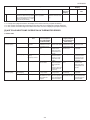
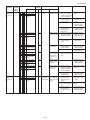
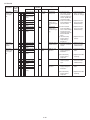
[2] AIR TO AIR HEAT PUMP OPERATION IN THERMISTOR ERROR
1. Indoor unit
Item
Room temperature
thermistor (TH1)
Heat exchanger
thermistor (TH2)
Mode
Control operation
Auto
Operation mode
judgment
Cooling
Frequency control
Dehumidifying
Room temperature
memory
Frequency control
Heating
Frequency control
Cooling
Dehumidifying
Heating
Freeze prevention
Cold air prevention
When resistance
is low (temperature judged higher than actual)
Cooling mode is activated even if room
temperature is low.
Room becomes too
cold.
Short-circuit
When resistance
is high (temperature judged lower
than actual)
Cooling mode is acti- Heating mode is acvated in most cases. tivated even if room
temperature is high.
Air/air heat pump
Room does not
operates in full
become cool.
power even when
set temperature is
reached.
Normal operation.
Room temperature Normal operation.
is stored in memory as 31.0°C, and
compressor does
not stop.
Room does not
Hot keep status
Room becomes too
become warm.
results immediate- warm.
ly after operation
starts.
Frequency does not
increase above 30
Hz (40 Hz).
Indoor unit evapora- Indoor unit evapora- Compressor stops
tor may freeze.
tor may freeze.
occasionally.
Cold air prevention
Cold air prevention Compressor operdeactivates too soon ates at low speed or deactivates too slow.
and cold air disstops, and frequency
charges.
does not increase.
3-3
Open-circuit
Heating mode is
always activated.
Compressor does
not operate.
Room temperature
is stored in memory as 18.5°C, and
compressor does
not operate.
Air/air heat pump
operates in full
power even when
set temperature is
reached.
Compressor does
not operate.
Cold air prevention
does not deactivate,
and indoor unit fan
does not rotate.
AY-ZP35PR
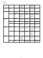
2. Outdoor unit
Item
Mode
Compressor cham- Cooling
ber thermistor
Dehumidifying
(TH1)
Heating
Heat exchanger
thermistor (TH2)
Cooling
Dehumidifying
Heating
Outside air temper- Auto
ature thermistor
(TH3)
Cooling
Dehumidifying
Suction pipe thermistor (TH4)
2-way valve thermistor (TH5)
Control operation When resistance
is low (temperature judged higher
than actual)
Expansion valve
Compressor opercontrol and comates, but room does
pressor protection not become cool or
warm (expansion
valve is open).
Outdoor unit heat Compressor operexchanger overates at low speed
heat prevention
or stops.
Expansion valve
Defrosting operacontrol
tion is not activated
Defrosting
as needed, and
frost accumulates
on outdoor unit
(expansion valve is
closed).
Cooling mode is
Operation mode
judgment
activated even if
room temperature
is low.
Operation not
Normal operation.
affected
Heating
Rating control
Defrosting
Cooling
Dehumidifying
Expansion valve
control
Heating
Expansion valve
control
Cooling
Dehumidifying
Expansion valve
control
Heating
Operation not
affected
Short-circuit
Compressor high
temperature error
indication.
When resistance
is high (temperature judged lower
than actual)
Layer short-circuit
or open-circuit may
result in compressor in normal operation.
Normal operation.
Outdoor unit thermistor short-circuit
error indication.
Outdoor unit ther- Defrosting operamistor short-circuit tion is activated
error indication.
unnecessarily, and
room does not
become warm
(expansion valve is
open).
Outdoor unit ther- Heating mode is
mistor short-circuit activated even if
error indication.
room temperature
is high.
Outdoor unit ther- Normal operation.
mistor short-circuit
error indication.
Defrosting opera- Outdoor unit ther- Defrosting operation is activated
mistor short-circuit tion is not activated,
unnecessarily.
error indication.
and frost accumulates on outdoor
unit.
Compressor oper- Outdoor unit ther- Frost accumulates
ates, but room does mistor short-circuit on evaporator inlet
not become cool
error indication.
section, and room
(expansion valve is
does not become
cool (expansion
open).
valve is closed).
Compressor oper- Outdoor unit ther- Frost accumulates
ates, but room does mistor short-circuit on expansion valve
outlet section, and
not become warm error indication.
room does not
(expansion valve is
become warm
open).
(expansion valve is
closed).
Frost accumulates Outdoor unit ther- Compressor operon indoor unit evap- mistor short-circuit ates, but room does
error indication.
orator and room
not become cool
does not become
(expansion valve is
cool (expansion
open).
valve is closed).
Normal operation. Outdoor unit ther- Normal operation.
mistor short-circuit
error indication.
3-4
Open-circuit
Outdoor unit thermistor open-circuit
error indication.
Outdoor unit thermistor open-circuit
error indication.
Outdoor unit thermistor open-circuit
error indication.
Outdoor unit thermistor open-circuit
error indication.
Outdoor unit thermistor open-circuit
error indication.
Outdoor unit thermistor open-circuit
error indication.
Outdoor unit thermistor open-circuit
error indication.
Outdoor unit thermistor open-circuit
error indication.
Outdoor unit thermistor open-circuit
error indication.
Outdoor unit thermistor open-circuit
error indication.
AY-ZP35PR
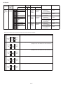
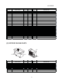
[3] THERMISTOR TEMPERATURE CHARACTERISTICS
1. Indoor unit thermistor temperature characteristics
TH1
TH2
K
100
CN2
4
3
2
1 CN2
80
Resistance
(K )
-
-
+
+
60
Tester
40
Tester
Thermistor
Symbol
Room temperature
TH1
(CN2)
Heat exchanger
TH2
(CN2)
Heat exchanger thermistor TH2 (orange)
Resistance at 25 : 4.431k
Room temperature thermistor TH1 (yellow)
Resistanceat25 : 10 k
20
Before measuring resistance,
disconnect connectors as shown
Yellow above.
Color
Orange
0
-10
0
10
20
30
Temperature(
40
)
TH1 Room temperature thermistor
TH2 Heat exchanger thermistor
2. Outdoor unit thermistor temperature characteristics
Connector
CN8
Connector
CN8
1
10
+
1
10
+
-
-
500K
40K
Tester
Resistance 400K
(K )
Resistance at 0
14.57 k
Resistance
(K ) 30K
300K
Resistance at 25
52.76 k
5.8K
3.34K
4.17K 2.28K
100K
Resistance at 25
4.431 k
TH2 TH5
20K
200K
Tester
(In case of TH2 heat exchanger thermistor)
10K
1.908K
0
0
-20
0
20
60
80
Temperature(
100
120
-20
20
40
60
Temperature(
No.
)
TH2 Heat exchanger thermistor
TH3 Outdoor air temperature thermistor
TH4 Suction thermistor
TH5 2-way valve thermistor
TH1 Compressor thermistor
Thermistor
0
)
Connector
Color
Compressor thermistor
TH1 No. (1) - No. (2)
Red
Heat exchanger thermistor
TH2 No. (3) - No. (4)
Orange
Outdoor air temperature thermistor TH3 No. (5) - No. (6)
Green
Suction thermistor
TH4 No. (7) - No. (8)
Black
2-way valve thermistor
TH5 No. (9) - No. (10)
Yellow
Before measuring resistance,
disconnect connectors from PWB.
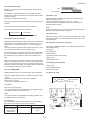
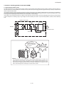
[4] HOW TO OPERATE THE OUTDOOR UNIT INDEPENDENTLY
1. Cooling in 40 Hz fixed mode
To operate the outdoor unit independently, short-circuit the sections indicated by arrows in the diagram below with an adapter, and apply 220-240
VAC between (1) and (N) on the terminal board of the outdoor unit. This allows the outdoor unit to be operated in cooling mode independently.
(Do not operate the outdoor unit in this condition for an extended period of time.)
3-5
AY-ZP35PR
[5] GENERAL TROUBLESHOOTING CHART
1. Indoor unit does not turn on
Main cause
Cracked PWB.
(Cracked pattern)
Open-circuit in FU1 (250 V, 2.5A).
Inspection method
Check visually.
Normal value/condition
There should be no cracking in
PWB or pattern.
There should be no open-circuit.
Check melting of FU1.
Remedy
Replace PWB.
Replace PWB.
2. Indoor unit fan does not operate
Main cause
Open-circuit in heat exchanger
thermistor (TH2) (in heating operation)
Inspection method
Measure thermistor resistance
(dismount for check).
Disconnected heat exchanger
thermistor (TH2) (in heating operation)
Inspect connector on PWB.
Check thermistor installation condition.
Normal value/condition
Refer to THERMISTOR TEPERATURE CHARACTERISTICS-1
There should be no open-circuit
or faulty contact.
Thermistor should not be disconnected.
Remedy
Replace thermistor.
Normal value/condition
Fan speed should change except
during dehumidifying operation,
ventilation, light dehumidifying
operation, internally normal operation
Remedy
Explain to user.
Normal value/condition
2.5 V or higher (two batteries in
series connection)
As indicated on battery compartment.
Signal should be received when
light is turned off.
Signal may not be received
sometimes due to effect of Sevick
light.
Signal should be received within
range specified in manual.
Wires of light receiving section
should not have any damage
caused by pinching.
Tester indicator should move
when signal is received.
Remedy
Install new batteries.
Replace thermistor.
Install correctly.
3. Indoor unit fan speed does not change
Main cause
Remote control not designed to
allow fan speed change.
Inspection method
Check operation mode.
4. Remote control signal is not received
Main cause
Batteries at end of service life.
Inspection method
Measure battery voltage.
Batteries installed incorrectly.
Check battery direction.
Lighting fixture is too close, or fluorescent lamp is burning out.
Use Sevick light (Hitachi).
Turn off light and check.
Check if Sevick light (Hitachi) is
used.
Operating position/angle is inappropriate.
Open-circuit or short-circuit in wiring of light receiving section.
Operate within range specified in
manual.
Check if wires of light receiving
section are caught.
Defective light receiving unit.
Check signal receiving circuit
(measure voltage between terminals 7 and 8 of connector CN7).
Check for water and rust.
Dew condensation on light receiving unit.
Install batteries in indicated direction.
Change light position or install
new fluorescent lamp.
Replace light or change position.
Explain appropriate handling to
user.
Replace wires of light receiving
section.
Replace PWB.
Signal should be received within
range specified in manual.
Take moisture-proof measure for
lead wire outlet of light receiving
section.
Normal value/condition
Louvers should operate smoothly.
Remedy
Remove or correct catching section.
Install correctly.
5. Louvers do not move
Main cause
Caught in sliding section.
Disconnected connector (CN3,
CN4 on relay PWB, louver motor
side)
Contact of solder on PWB
(connector section on PWB)
Inspection method
Operate to see if louvers are
caught in place.
Inspect connectors.
Check visually.
Connectors or pins should not be
disconnected.
There should not be solder contact.
Correct contacting section.
Normal value/condition
Grounding wires should be connected properly.
Remedy
Connect grounding wires properly.
6. There is noise in TV/radio
Main cause
Grounding wires not connected
properly.
Inspection method
Check grounding wire connections.
3-6
AY-ZP35PR
Main cause
TV/radio is placed too close to
outdoor unit.
Inspection method
Check distance between TV/radio
and outdoor unit.
Normal value/condition
If TV/radio is placed too close, it
may become affected by noise.
Remedy
Move TV/radio away from outdoor
unit.
Normal value/condition
Terminal board 1-N: 230 VAC, 50
Hz
Terminal board 2: serial signal
Remedy
Correct wiring.
7. Compressor does not start
Main cause
Erroneous inter-unit connection.
Inspection method
Check wiring between indoor and
outdoor units.
Dama ged IPM.
Dried-up electrolytic capacitor.
Blown outdoor unit fuse.
Check IPM continuity.
Check electrolytic capacitor.
Check 20-A fuse.
Check 15-A fuse.
Power supply voltage is too low.
Measure power supply voltage
during startup.
Supply current and touch compressor cover (sound absorbing
material) to check if operation
starts.
Compressor lock.
Fuse should not be blown.
230± 10 VAC, 50 Hz
Compressor should start normally.
R eplace IPM.
Replace electrolytic capacitor.
Replace fuse/diode bridge.
Replace fuse.
Replace outdoor unit PWB
assembly.
Make sure that power supply voltage is 198 V or higher.
Apply external impact to compressor.
Replace compressor.
8. Operation stops after a few minutes and restarts, and this process repeats
Main cause
Dried-up electrolytic capacitor.
Layer short-circuit in expansion
valve coil.
Inspection method
Measure 320-VDC line voltage.
Measure resistance.
Normal value/condition
250 V or higher.
46±3Ω in each phase (at 20°C)
Remedy
Replace electrolytic capacitor.
Replace coil.
CAUTION: If fuse FU1/FU4/FU5 (outdoor unit control circuit board) is blown, be careful of charging voltage in inverter electrolytic capacitor C9, C10.
To discharge stored electricity, unplug the power cord and connect the plug of a soldering iron (230VAC, 50W) between the positive and
negative terminals of inverter electrolytic capacitor C9, C10.
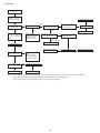
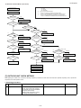
[6] MALFUNCTION (PARTS) CHECK METHOD
1. Procedure for determining defective outdoor unit IPM/compressor
The following flow chart shows a procedure for locating the cause of a malfunction when the compressor does not start up and a DC overcurrent indication error occurs.
3-7
AY-ZP35PR
Connect power cord
to AC outlet.
Check 220-240 VAC
between (1) and (N)
on outdoor unit PWB.
Replace outdoor unit PWB.
YES
Is LED1 on outdoor
unit flashing?
NO
Does LED1 remain lit?
No
(unlit)
NO
Check 320 VDC between
pins IPM (20) and (24)?
NO
Disconnect (CN3) lead
wires of FAN motor.
LED1 is flashing.
YES
YES
YES
YES
Replace FAN motor.
Using remote control,
operate air conditioner
so that compressor
starts.
Serial signal error.
Check inter-unit wiring.
Check indoor and
outdoor unit PWBs.
FUSE and+12 V, +15 V,
+18V on PWB
NO
Disconnect (CN12)
expansion valve.
YES
(LED1 is still off)
Replace outdoor unit PWB.
Compressor starts up.
Immediately
after startup
Replace expansion valve.
Does LED1 indicate
DC overcurrent error?
YES
NO
Does LED1 indicate
rotation error?
NO
Normal
YES
YES
NO
LED1 is flashing.
Replace outdoor unit PWB.
Replace outdoor unit
PWB.
Check compressor.
2/3-way valve closed.
Refrigerant shortage.
Replace outdoor unit PWB.
NO
Replace compressor.
CAUTION: Please take care for electrical shock when you work to change defective parts or disconnect wires of defective application.
The outdoor unit has energy changed for a while even after unplugging the power supply cord.
After changing the part or unit, please retry check procedure from the beginning.
3-8
AY-ZP35PR
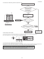
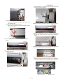
2. Procedure for determinin g defective expansio n valve
Measure resistance in expansion valve coil.
Normal resistance between red
terminal of expansion valve
lead wire and white or orange
terminal,gray terminal of
expansion valve lead wire and
yellow or blue terminal :
about 46 (at 20 )
LED
(red)
NO
YES
Checker
Insert checker shown at left into
connector (CN12) on control PWB, and
operate air conditioner.
5.6K 5.6K 5.6K 5.6K
Replace control PWB.
6
5
4
3
2
NO
1
Do LEDs on checker light in orderly
sequence
(lighting of 1 LED => lighting of 2 LEDs)
Connector
J.S.T. XNIRP-06V-A-S
Terminal
SXNI-001T-P0.6
YES
If frost accumulates on 2-way valve after 10 to 20
minutes of cooling operation, then thermistors with
yellow and black lead wires may be defective. Check
these thermistors.
Thermistors in
normal condition
Defective thermistor
Replace thermistor assembly.
Replace expansion
valve assembly.
3. Dio de bridge check method
Turn off the power and let the inverter electrolytic capacitor (C9, C10) discharge completely. Then use a tester and check continuity.
When using a digital tester, the (+) and (-) tester lead wires in the table must be reversed.
Needle-type tester
45
B
Normal resistance value
(several M )
Value in ( ) is for digital tester.
4. Inverter electrolytic capacitor (C9, C10) check method
Turn off the power, let the inverter electrolytic capacitor (C9, C10) discharge completely, and remove the capacitor from the control printed circuit
board (PWB). First, check the case for cracks, deformation and other damages. Then, using a needle-type tester, check continuity.
Deter minat ion of norm al co nditi on
The tester needle should move on the scale and slowly returns to the original position. The tester needle should move
in the same way when polarities are reversed. (When measurement is taken with the polarities reversed, the tester
needle exceeds the scale range. Therefore, let the capacitor discharge before measurement.)
3-9
AY-ZP35PR
5. IPM check method
Turn off the power, let the large capacity electrolytic capacitor (C10) discharge completely, and dismount the IPM. Then, using a tester, check leak
current between C and E.
When using a digital tester, the (+) and (-) tester lead wires in the table must be reversed.
Needle-type tester
(-)
(+)
P
N
U
V
W
Needle-type tester
(-)
(+)
U
N
V
W
Normal resistance value
∞
(several MΩ)
Normal resistance value
∞
(several MΩ)
Values in ( ) are for digital tester.
5.1. IPM internal circuit diagram
3-10
AY-ZP35PR
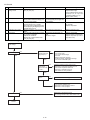
6. DC Over Current Error ( 6-0 error)
*1
6-0 error memory is
recorded.
Check the connection of compressor lead wire on PWB.
TU : RED
TV : WHITE
TW : ORANGE
Refer to "IPM CHECK METHOD".
Check the connection of compressor terminal marking.
Refer to " DISASSEMBLING PROCEDURE OUTDOOR UNIT".
Check to make sure thermistors are installed in correct portions.
Refer to "THERMISTOR TEMPERATURE CHARACTERISTICS".
*2
*3
START
*4
Are valves(2-way
and 3-way) close?
No
Yes
Fullyopenstop valves
Does compressor
rotate?
Does compressor rotate
more than 30 seconds?
Yes
Is IPM PWB floating
from the heat sink?
*1
No
Check IPM
lead wire.
normal
Check the AC power
supply voltage when
compressor rotate.
Modify the connection of
compressor lead wire on PWB.
abnormal
(rated voltage±10%)
*2
Check
short circuit.
Fix IPM PWB with screws securely.
abnormal
abnormal
Connect stable power supply.
normal
normal
Replace PWB.
*3
Check compressor
terminal.
Yes
Cooling mode?
abnormal
No
normal
Modify compressor terminal
marking.
ReplacePWB
Heat i n g m o d e
*4
Check indoor
exchanger termistor and
discharge thermistor.
normal
Does compressor
rotate?
Check indoor
heat exchanger.
Co o l i n g m o d e
*4
abnormal
Check outdoor
exchanger termistor and
discharge thermistor.
Modify or replace termistor.
abnormal
normal
Clean indoor heat exchanger.
normal
Check outdoor
heat exchanger.
normal
abnormal
Modify or replace termistor.
abnormal
Clean indoor heat exchanger.
ReplaceCompressor
Check the refrigerant amount.
Check the discharge pressure.
Check the installation condition.
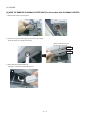
[7] OUTDOOR UNIT CHECK METHOD
After repairing the outdoor unit, conduct the following inspection procedures to make sure that it has been repaired completely. Then, operate the
compressor for a final operation check.
1. Checking procedures
No
1
Item
Preparation
Check method
Normal value/condition
Disconnect compressor cords (white,
orange, red: 3 wires) from compressor terminals, and connect simulated
load (lamp used as load).
Operate air/air heat pump in cooling
or heating test operation mode.
3-11
Remedy
AY-ZP35PR
No
Item
Check method
Normal value/condition
Remed y
2
Inverter DC power supply
voltage check
Measure DC voltage between IPM
pins (31) and (35).
320 VDC
Replace control PWB.
Replace diode bridge.
Correct soldered section of Fasten tabs (T1, T2, T5 - T3) on control PWB and IMP (S, C, R).
(Repair solder cracks.)
Replace control PWB.
3
IPM circuit check
4
Compressor check
Each voltage should be normal.
All 3 lamps (load) should light with
same intensity.
Resistance value at 20°
C --- 0.65Ω Correct connections at compressor terminals.
Replace compressor.
5
Expansion valve check
6
Final check
Check that 3 lamps (load) light.
Check position detection voltage (+15
V, 5 V) on control PWB.
Measure compressor coil resistance
(for each phase of U, V and W).
Use multi-meter or digital tester capable of displaying two digits right of the
decimal point (0.01Ω).
Measure expansion valve coil resistance.
Turn off power, and connect compressor cords to compressor.
Operate air conditioner.
Measure DC voltage between IPM
pins (20) and (24).
C)
Each phase 46±3Ω (at 20°
Replace
expansion valve.
Compressor should operate normally.
280 VDC or higher.
Replace control PWB.
Replace outdoor unit thermistor.
Replace compressor (in case of
compressor lock).
2. Troubleshooting of outdoor unit electric components
Check 220-240VAC
input voltage.
Does LED light?
NO
Check 320VDC
between IPM pins
(20) and (24) ?
NO
YES
YES
Check switching
power supply
output of 12 VDC,
15 VDC ?
NO
Short-circuit in DC fan motor
Short-circuit in IPM
Short-circuit in diode bridge
Blown fuse
Defective electrolytic capacitor
Wire disconnection, PWB pattern damage
Short-circuit in PAM IGBT (Q5)
Defective switching power supply circuit
Malfunction of 3-terminal regulator IC4, IC1
Short-circuit in expansion valve coil
Malfunction of transistor array IC7
Solder contact or other problems
YES
Check 5 VDC
output ?
NO
Malfunction of 3-terminal regulator IC3, IC2.
YES
Microcomputer oscillator error
Malfunction of microcomputer reset IC
Malfunction of microcomputer
Does LED flash?
NO
Malfunction of serial signal circuit
Check wiring between indoor and outdoor units.
YES
Normal
3-12
AY-ZP35PR
3. Caution in checking printed circuit boards (PWB)
3.1. Non-insulated control circuit
The GND terminals of the low-voltage circuits (control circuits for microcomputer and thermistors and drive circuits for expansion valve and relays) on
the control printed circuit board (PWB) are connected to the compressor drive power supply (320-VDC negative terminal). Therefore, exercise utmost
caution to prevent electric shock.
If a measuring instrument used for the test is grounded, its chassis (ground) has the same electric potential as the 0-V probe. Since non-insulated circuits have the following voltage potential difference from the ground, connection of the grounding wire results in a short-circuit between the 0-V line
and the ground, thus allowing an excessive current to flow to the tester to cause damage.
If the sheaths of the thermistor lead wires or expansion valve lead wires inside the outdoor unit become damaged due to pinching by the front panel
or other metal parts or contacting a pipe, a high voltage can flow and destroy the circuits. To prevent these problems, carefully conduct assembly
work.
Outdoor unit circuits
Terminal board
Point (E)
Reactor
1
+
-
AC230V
IPM
M
N
Compressor motor
Ground
0-V line
Point (F)
2
Do not touch the
cabinet or bring metal
parts into contact with
the cabinet.
Danger!!
Do not connect
the grounding
wire.
Reason
The oscilloscope (chassis ground) has the same electric potential as the 0-V probe. The
entire electronic control section of the outdoor unit has a voltage potential difference from
the ground as shown in the above diagram. When the oscilloscope is set up, the 0-V line
and the ground voltage (ground) will be short-circuited, resulting in an excessive current
flow to cause damage to the oscilloscope or indoor electric circuits.
3-13
AY-ZP35PR
[8] TROUBLESHOOTING GUIDE
1. Self-Diagnosis Function
1. Indoor unit
To display the self-diagnosis, hold down the AUX button for over 5 seconds on the indoor unit when the indoor unit is not operating.
The operation lamp (green), timer lamp (orange) and Plasmcluster lamp (blue) flash to indicate the information of mulfunction.
If the power cord is unplugged or the circuit breaker is turned off, the self-diagnosis memory is lost.
AUX
PLASMACLUSTER Lamp (blue)
OPERATION Lamp (green)
TIMER Lamp (orange)
Display of self-diagnosis result
The operation lamp (green) and the Plasmacluster lamp (blue) flash in synchronization with the timer lamp (orange).
Timer lamp (1 cycle)
2. Outdoor unit
The self-diagnosis is indicated the error information by flashing LED1 on the outdoor unit.
The self-diagnosis of outdoor unit is displayed for about 3-10 minutes. Then, the LED1 returns to normal display.
1-second
ON
1-second
ON
1-second
ON
1-second
ON
ON
LED1
Normal
OFF
1-second
OFF
1-second
OFF
1-second
OFF
2-time
1-second
ON
0.5-second
ON
0.5-second
ON
1-second
ON
ON
2-time
OFF
1-second
OFF
1-second
OFF
1-second
OFF
3-time
1-second
ON
0.5-second
ON
0.5-second
ON
0.5-second
ON
ON
3-time
OFF
1-second
OFF
3-14
1-second
OFF
1-second
OFF
1-second
ON
AY-ZP35PR
[9] CHART
<INDOOR UNIT>
:1-second ON / 1-second OFF
Problem
symptom
Outdoor
unit indication
(LED1)
Normal con- Normal
dition
blinking
Indoor and
outdoor units
do not operate.
1-time
Indoor unit
Lamp
Timer (Orange)
Malfunction No.
Main Sub
Content of diagnosis
Main
0
Normal
Plasmacluster
(Blue)
Timer (Orange)
1
0
Outdoor unit Heat exchanger
thermistor
thermistor short
short-circuit circuit error
Plasmacluster
(Blue)
Timer (Orange)
1
Timer (Orange)
2
Operation (Green)
Plasmacluster
(Blue)
Timer (Orange)
3
2-way valve
thermistor short
circuit error
Operation (Green)
Plasmacluster
(Blue)
Timer (Orange)
2
0
Cycle temperature
Operation (Green)
Plasmacluster
(Blue)
Timer (Orange)
Compressor dis- (Temporary stop for cycle
charge overheat. protection)
2
Outdoor unit heat (Temporary stop for cycle
exchanger over- protection)
heat.
-
3
Indoor unit heat (Temporary stop for cycle
exchanger over- protection)
heat.
-
4
IPM high temper- (Temporary stop for cycle
ature error
protection)
-
5
IPM high temper- (1) Measure resistance (1) Replace the outature error
of the heat-sink therdoor unit PFCM
mistor.
PWB or control
PWB assembly or
change the heatsink thermistor.
Operation (Green)
Plasmacluster
(Blue)
Timer (Orange)
Operation (Green)
Indoor and
outdoor units
do not operate.
Plasmacluster
(Blue)
Timer (Orange)
(1) Ensure unobstructed air flow
from the outdoor
unit air outlet.
(2) Connect power
supply of proper
voltage.
(3) Charge the specified amount of
refrigerant.
(4) Replace the outdoor unit compressor thermistor
assembly.
(5) Replace the
expansion valve
coil, expansion
valve or outdoor
unit control PWB
assembly.
-
1
Operation (Green)
Plasmacluster
(Blue)
Timer (Orange)
Compressor high (1) Check the outdoor
temperature
unit air outlet for
error
blockage.
(2) Check if the power
supply voltage is AC
230V at full power.
(3) Check the pipe connections for refrigerant leaks.
(4) Measure resistance
of the outdoor unit
compressor thermistor.
(5) Check the expansion
valve for proper
operation.
Operation (Green)
Plasmacluster
(Blue)
Timer (Orange)
(1) Measure the resis- (1) Replace the outtance of the outdoor
door unit therunit thermistors.
mistor assembly.
Outdoor temper- (2) Check the lead wire (2) Replace the outature thermistor
of the outdoor unit
door unit thershort circuit error
thermistor for torn
mistor assembly.
sheath and shortcircuit.
Suction ther(3) No abnormality
(3) Replace the outmistor short cirfound in above
door unit control
cuit error
inspections (1) and
PWB assembly.
(2).
Plasmacluster
(Blue)
Indoor unit
operates.
Outdoor unit
does not
operate temporarily.
Sub
0
Operation (Green)
2-time
Action
Operation (Green)
Operation (Green)
Indoor and
outdoor units
do not operate.
Check point
Operation (Green)
Plasmacluster
(Blue)
3-15
AY-ZP35PR
Problem
symptom
Indoor unit
operates.
Outdoor unit
does not
operate temporarily.
Indoor and
outdoor units
do not operate.
Outdoor
unit indication
(LED1)
3-time
Indoor unit
Lamp
Timer (Orange)
Malfunction No.
Main Sub
Content of diagnosis
Main
0
Dry operation
5
0
Outdoor unit Heat exchanger
thermistor
thermistor open
open-circuit circuit error
Plasmacluster
(Blue)
5-time
Timer (Orange)
Operation (Green)
Plasmacluster
(Blue)
Timer (Orange)
Plasmacluster
(Blue)
Timer (Orange)
2
Suction thermistor open circuit error
3
Operation (Green)
4
Discharge thermistor open circuit error
5
Heat sink thermistor open circuit error
Operation (Green)
Plasmacluster
(Blue)
Timer (Orange)
Operation (Green)
Indoor and
outdoor units
do not operate.
6-time
Plasmacluster
(Blue)
Timer (Orange)
6
0
Operation (Green)
Plasmacluster
(Blue)
Timer (Orange)
(2) Replace the outdoor unit thermistor assembly.
(3) Check the lead wires (3) Replace the outof thermistors on the
door unit theroutdoor unit control
mistor assembly.
PWB for open-circuit.
2-way valve ther- (4) No abnormality
(4) Replace the outmistor open cirfound in above
door unit control
cuit error.
inspections (1)
PWB assembly.
through (3).
Plasmacluster
(Blue)
Plasmacluster
(Blue)
Timer (Orange)
-
(1) Check connector of (1) Correct the instalthe outdoor unit therlation.
mistor for secure
installation.
Outdoor temper- (2) Measure resistance
ature thermistor
of outdoor theropen circuit error
mistors.
Operation (Green)
Timer (Orange)
Temporary stop (Temporary stop for cycle
due to dehumidi- protection)
fying operation
1
Operation (Green)
Action
Sub
3
Operation (Green)
Check point
Outdoor unit DC over current Go to “DC Over Current Error (6-0 error)”.
DC Current error
1
IPM pin level
error
Operation (Green)
Plasmacluster
(Blue)
3-16
(1) Check the IPM is
(1) Replace the outattached correctly to
door unit IPM PWB
the outdoor unit IPM
assembly.
PWB.
AY-ZP35PR
Problem
symptom
Indoor and
outdoor units
do not operate.
Outdoor
unit indication
(LED1)
7-time
Indoor unit
Lamp
Timer (Orange)
Malfunction No.
Main Sub
7
0
Operation (Green)
Content of diagnosis
Main
Plasmacluster
(Blue)
Timer (Orange)
Plasmacluster
(Blue)
Timer (Orange)
1
AC current error
when OFF
2
AC maximum
current error
Operation (Green)
Plasmacluster
(Blue)
Timer (Orange)
3
AC current deficiency error
Operation (Green)
Plasmacluster
(Blue)
Indoor and
outdoor units
do not operate.
8-time
Timer (Orange)
Operation (Green)
8
0
Abnormal
wire check
Plasmacluster
(Blue)
Abnormal wire
check error
(1) Check the outdoor
unit air outlet for
blockage.
(1) Ensure unobstructed air flow
from the outdoor
unit air outlet.
(2) Check the outdoor
(2) Check the outdoor
unit fan for proper
unit fan motor.
rotation.
(1) IPM continuity check (1) Replace the outdoor IPM PWB
(1) Check the outdoor
unit air outlet for
blockage.
(1) Ensure unobstructed air flow
from the outdoor
unit air outlet.
(2) Check the outdoor
(2) Check the outdoor
unit fan for proper
unit fan motor.
rotation.
(1) Check if there is an (1) Replace the outopen-circuit in the
door unit control
secondary winding
PWB assembly.
of the current transformer of the outdoor
unit control PWB.
(2) Check if the refriger- (2) Charge the speciant volume is abnorfied amount of
mally low.
refrigerant.
(3) Check if the refriger- (3) Correct refrigerant
ant flows properly.
clogs. (Stop valve,
pipe, expansion
valve)
(1) Check the expansion (1) Replace the outvalve. (unit A - C)
door control board
assembly.
(2) Are four expansion (2) Reattach
valves connected by
mistake
(3) Check the wiring
between units.
3-17
Action
Sub
Outdoor unit AC over current
AC Current error
Operation (Green)
Check point
(3) Check the wiring
between units.
AY-ZP35PR
Problem
symptom
Indoor and
outdoor units
do not operate.
Outdoor
unit indication
(LED1)
9-time
Indoor and
outdoor units
do not operate.
Indoor and
outdoor units
do not operate.
Lamp
Timer (Orange)
Malfunction No.
Main Sub
9
0
Operation (Green)
Content of diagnosis
Main
Cycle temperature
Plasmacluster
(Blue)
Timer (Orange)
Indoor and
outdoor units
do not operate.
Indoor and
outdoor units
do not operate.
Indoor unit
4
Operation (Green)
Plasmacluster
(Blue)
10-time
Timer (Orange)
10
0
Operation (Green)
Plasmacluster
(Blue)
Timer (Orange)
EEPROM
error
Plasmacluster
(Blue)
Timer (Orange)
Thermistor
installation error
or 4-way valve
error.
(1) Check the thermistor (heat
exchanger) and (2way valve) are
installed in correct
positions.
(2) Check resistance of
thermistors (heat
exchanger and 2way valve).
(3) Check the 4-way
valve for proper
operation.
(4) No abnormality
found in above
inspections (1)
through (3).
4 way valve error (1) Check the indoor/
or Gas leak error
outdoor heat
exchanger thermistors are installed
in correct positions.
(2) Check if the refrigerant volume is abnormally low.
(3) Check the 4-way
valve for proper
operation.
EEPROM (outdoor) data error
EEPROM (outdoor) data error
2
CPU (outdoor)
RAM data error
Operation (Green)
Plasmacluster
(Blue)
3-18
Action
Sub
1
Operation (Green)
Check point
(1) Correct the installation.
(2) Change the specified amount of
refrigerant.
(3) Replace the 4-way
valve.
(4) Replace the outdoor unit control
PWB assembly.
(1) Correct the installation.
(2) Change the specified amount of
refrigerant.
(3) Replace the 4-way
valve.
(1) Replace the outdoor unit control
PWB assembly.
AY-ZP35PR
Problem
symptom
Indoor and
outdoor units
do not operate.
Outdoor
unit indication
(LED1)
11-time
Indoor unit
Lamp
Timer (Orange)
Malfunction No.
Main Sub
11
0
Operation (Green)
Plasmacluster
(Blue)
Timer (Orange)
Content of diagnosis
Main
Check point
Sub
Outdoor unit Outdoor unit DC (1) Check connector
(1) Correct the instalDC fan
fan rotation error
CN3 of the outdoor
lation.
unit DC fan motor for
secure installation.
(2) Check the outdoor
(2) Replace the outunit fan motor for
door unit fan
proper rotation.
motor.
(3) Check fuse FUSE5. (3) Replace the outdoor unit control
PWB assembly.
(4) No abnormality
(4) Replace the outfound in above
door unit control
inspections (1)
PWB assembly.
through (3).
Outdoor unit DC (1) Check if the fan IPM (1) Replace the outfan drive IC error
terminal resistance
door unit control
values are uniform.
PWB assembly.
1
Operation (Green)
Plasmacluster
(Blue)
(2) Outdoor unit fan
motor continuity
check.
Timer (Orange)
Outdoor unit DC (1) Check the outdoor
fan lock error
unit fan motor for
proper rotation.
(2) (1):Normal
3
Detection error of (1) (Temporary stop for
DC fan negative
DC fan circuit protection)
rotation before
compressor is
driven
Detection error of
(1) Replace the outinverter current
door unit control
for DC fan
PWB assembly.
Operation (Green)
Plasmacluster
(Blue)
Timer (Orange)
4
Operation (Green)
Plasmacluster
(Blue)
Timer (Orange)
5
Plasmacluster
(Blue)
12-time
Timer (Orange)
Operation (Green)
Plasmacluster
(Blue)
12
0
(1) Replace the outdoor unit control
PWB assembly.
(2) Replace the outdoor unit fan.
-
Outdoor unit DC (1) Check connector
(1) Correct the instalfan open conCN3 of the outdoor
lation.
nector error
unit DC fan motor for
secure installation.
Operation (Green)
Indoor and
outdoor units
do not operate.
(2) Replace the outdoor unit fan.
2
Operation (Green)
Plasmacluster
(Blue)
Timer (Orange)
Action
(2) No abnormality
found in above
inspections (1).
Thermal
Thermal fuse
(1) Check the thermal
fuse in ter- error in terminal
fuse in terminal
minal board board (for power
board (for Power
supply)
supply)
(2) Check connector
CN5 of the outdoor
unit.
(3) No abnormality
found in above
inspections (1) and
(2).
3-19
(2) Replace the outdoor unit control
PWB assembly.
(1) Replace terminal
board for Power
supply
(2) Correct the installation.
(3) Replace the outdoor unit control
PWB assembly.
AY-ZP35PR
Problem
symptom
Indoor and
outdoor units
do not operate.
Outdoor
unit indication
(LED1)
13-time
Indoor unit
Lamp
Timer (Orange)
Malfunction No.
Main Sub
13
0
Operation (Green)
Content of diagnosis
Main
DC compressor
Plasmacluster
(Blue)
Timer (Orange)
1
Operation (Green)
Plasmacluster
(Blue)
Timer (Orange)
2
Plasmacluster
(Blue)
Indoor and
outdoor units
do not operate.
Timer (Orange)
3
Operation (Green)
14-time
Plasmacluster
(Blue)
Timer (Orange)
14
0
Operation (Green)
Sub
Compressor
startup error
(1) Check the colors
(1) Correct the instal(red, white, orange)
lation. (U: Red, V:
of the compressor
White, W: Orange)
cords for proper connection. (PWB side,
compressor side)
Compressor
(2) Check if the IPM ter- (2) Replace the outrotation error.
minal resistance valdoor unit control
(at 120o energizues are uniform.
PWB assembly.
ing)
Outdoor unit PAM over voltPAM
age error
Plasmacluster
(Blue)
Timer (Orange)
1
PAM clock error
2
PAM under voltage error
Operation (Green)
Plasmacluster
(Blue)
Timer (Orange)
Action
Compressor
(3) Check if outdoor
(3) Replace the outrotation error
main relay (MRY1)
door unit control
(at 180o energizturns on and voltage
PWB assembly.
ing)
of both end of the
condenser (C10) has
become DC290330V.
(4) No abnormality
(4) Replace the comfound in above
pressor.
inspections (1)
through (3).
Detection error of (1) Check the circuit of (1) Replace the outinverter current.
detection of inverter
door unit control
current.
PWB assembly.
Operation (Green)
Indoor and
outdoor units
operate.
Check point
Operation (Green)
Plasmacluster
(Blue)
(1) Check the AC power (1) Correct the instalsupply voltage for
lation.
fluctuation.
(2) No abnormality
found in above
inspection.
(1) Check the PAM
clock for proper
input.
(1) Replace the outdoor unit control
PWB assembly.
(1) Check the AC power (1) Correct the instalsupply voltage for
lation.
fluctuation.
(2) No abnormality
found in above
inspection.
3-20
(2) Replace the PWB
assembly.
(2) Replace the PWB
assembly.
AY-ZP35PR
Problem
symptom
Indoor unit
operates.
Outdoor unit
does not
operate.
Outdoor
unit indication
(LED1)
Lighting
or OFF
Indoor unit
Lamp
Timer (Orange)
Malfunction No.
Main Sub
17
0
Operation (Green)
Content of diagnosis
Main
Wiring
between
units
Check point
Sub
Serial open-cir- (1) Check the wires
cuit
between units.
Plasmacluster
(Blue)
(2)
(3)
(4)
(5)
(6)
Indoor unit
Lighting
operates.
or OFF
Outdoor unit
does not
operate.
Indoor and
Lighting
outdoor units or OFF
do not operate.
Indoor and
outdoor units
do not operate.
Indoor and
outdoor units
do not operate.
Normal
blinking
or OFF
Normal
blinking
or OFF
Timer (Orange)
18
0
Operation (Green)
Plasmacluster
(Blue)
Timer (Orange)
Wiring
between
units
1
Plasmacluster
(Blue)
Timer (Orange)
19
0
Operation (Green)
Serial short-cir- (1)
cuit
Indoor unit
fan
Indoor unit fan
error
Plasmacluster
(Blue)
Timer (Orange)
Operation (Green)
20
0
(1) Connect stable
power supply.
Correct the wiring.
Check voltage
(2) Replace the outbetween N and 1 the
door unit control
indoor/outdoor unit
PWB assembly.
terminal boards.
Check the outdoor
(3) Replace the fuse/
unit fuse.
outdoor unit control PWB assembly.
Check 15-V,13-V
(4) Replace the outand 5-V voltages on
door unit control
the PWB.
PWB assembly.
Check resistance
between IPM terminals.
Check pins No.5 and (5) Replace the outdoor unit fan
8 of connector CN3
motor.
of the outdoor unit
fan motor for shortcircuit.
No abnormality
(6) Replace the outfound in above
door unit control
inspections (1)
PWB board.
through (5).
Check the wiring
(1) Correct the wiring.
between units.
Serial erroneous (1) Check the wiring
wiring
between units.
Operation (Green)
Indoor unit EEPROM data
control PWB error
Plasmacluster
(Blue)
3-21
Action
(1) Correct the wiring.
(1) Check the indoor fan (1) Replace the indoor
motor for proper
fan motor.
rotating operation.
(Check fan lock.)
(2) Check the lead wire
of the indoor fan
motor for open-circuit.
(3) Check connector of
the indoor unit fan
motor for secure
installation.
(4) No abnormality
found in above
inspections (1)
through (3).
(1) (EEPROM read data
error)
(2) Replace the indoor
fan motor.
(3) Correct the installation of the indoor
fan motor connector.
(4) Replace the indoor
unit control PWB.
(1) Replace the indoor
unit control PWB.
AY-ZP35PR
Problem Outdoor
Indoor unit
symptom unit indication
Lamp
(LED1)
Indoor and Normal { { { { { Timer(Orange)
outdoor
blinking { { {
Operation(Green)
units operor OFF
{ Plasmacluster
ate.
(Blue)
Malfunction No.
Main Sub
26
1
{ { { { { Timer(Orange)
{{ {
Operation(Green)
{
Plasmacluster
(Blue)
2
{ { { { { Timer(Orange)
{{ {
Operation(Green)
{ { Plasmacluster
(Blue)
3
Content of diagnosis
Main
Check point
Sub
Indoor unit
room temperature
thermistor
Indoor unit room (1) Check connector of (1) Replace the thertemperature
thermistor for
mistor.
thermistor
secure installation.
Indoor unit
pipe temperature
thermistor
Indoor unit pipe
temperature
thermistor
Indoor unit
valve temperature
thermistor
(2) Check the tempera- (2) Replace the therture properties of
mistor.
the thermistor.
(1) Check connector of (1) Replace the therthermistor for
mistor.
secure installation.
(2) Check the tempera- (2) Replace the therture properties of
mistor.
the thermistor.
Indoor unit valve (1) Check connector of (1) Replace the thertemperature
thermistor for
mistor.
thermistor
secure installation.
(2) Check the tempera- (2) Replace the therture properties of
mistor.
the thermistor.
Malfunction indications due to erroneous wiring during air/air heat pump installation
Inter-unit wiring error mode
1
1
Indoor
unit N
N
2
2
Symptom
Malfunction diagnosis display
“18-1”
Malfunction diagnosis display
None
(Displays “18-0” when malfunction code is called out.)
Malfunction diagnosis display
None
(Displays “18-0” when malfunction code is called out.)
Malfunction diagnosis display
“18-1”
Malfunction diagnosis display
“18-1”
1
Outdoor
unit
2
1
Indoor
unit N
N
2
2
1
Outdoor
unit
3
1
Indoor
unit N
N
2
2
1
Outdoor
unit
4
1
Indoor
unit N
N
2
2
1
Outdoor
unit
5
1
Indoor
unit N
N
2
2
Action
1
Outdoor
unit
3-21
AY-ZP35PR
EHP6.0AA/I
CHAPTER 4. REFRIGERATION CYCLE
5GTXKEG/CPWCN
[1] SCHEMATIC DIAGRAM
Indoor unit
Evaporator
3
Flare coupling
Flare coupling
3-way
2-way
valve
valve
Heating
Cooling
Silencer
Strainer
s
Outdoor unit
Accumulator
4
1
Antifreeze
pipe
Silencer
Expansion
valve
Compressor
Coil
C
Reverse valve
Condenser
2
[2] STANDARD CONDITION
Indoor side
Dry-bulb Temp. (°
C)
Relative Humidity (%)
27
47
–
20
Cooling
Heating
*
Outdoor side
Dry-bulb Temp. (°
C)
Relative Humidity (%)
35
40
7
87
REFRIGERANT PIPE LENGTH 5m
[3] TEMPERATURE AT EACH PART AND PRESSURE IN 3-WAY VALVE
Model
NO. Condition
AY-ZP40PR
Cooling
Heating
Temp. on
(°
C)
60
58
61
57
Temp. on
(°
C)
37
3
37
3
Temp. on
(°
C)
17
25
17
25
Temp. on
(°
C)
16
6
16
7
1.0
2.2
1.0
2.2
3-way valve pressure (MPaG)
*
AY-ZP35PR
Cooling
Heating
On test run mode
[4] PERFORMANCE CURVES
NOTE
1) Indoor fan speed: Hi
2) Vertical adjustment louver "front”, Horizontal adjustment louver "level"
3) Indoor air temp. : Cooling 27°
C, Heating 20°
C
4) Power source : 230V, 50Hz
5) Compressor speed : Rated frequency
4–1
AY-ZP35PR
1. AY-ZP35PR
1.1. At Cooling
1.2. At Heating
㪎㪇㪇㩷
㪏㪌㪇㩷
㪏㪇㪇㩷
㪠㫅㫇㫌㫋㩷㩿䌗㪀
㪠㫅㫇㫌㫋㩷㩿㪮㪀
㪍㪌㪇㩷
㪍㪇㪇㩷
㪎㪌㪇㩷
㪎㪇㪇㩷
㪌㪌㪇㩷
㪍㪌㪇㩷
㪌㪇㪇㩷
㪍㪇㪇㩷
㪉㪇
㪉㪌
㪊㪇
㪊㪌
㪋㪇
㪋㪌
㪄㪈㪇
㪄㪌
㪇
㪌
㪈㪇
㪈㪌
㪦㫌㫋㫊㫀㪻㪼㩷㪸㫀㫉㩷㫋㪼㫄㫇㪅㩷㩿㷄㪀
㪊㪅㪌㩷
㪋㪅㪇㩷
㪊㪅㪇㩷
㪊㪅㪌㩷
㪟㪼㪸㫋㫀㫅㪾㩷㪺㪸㫇㪸㪺㫀㫋㫐㩷㩿㫂㪮㪀
㪚㫆㫆㫃㫀㫅㪾㩷㪺㪸㫇㪸㪺㫀㫋㫐㩷㩿㫂㪮㪀
㪦㫌㫋㫊㫀㪻㪼㩷㪸㫀㫉㩷㫋㪼㫄㫇㪅㩷䋨㷄䋩
㪉㪅㪌㩷
㪉㪅㪇㩷
㪊㪅㪇㩷
㪉㪅㪌㩷
㪉㪅㪇㩷
㪈㪅㪌㩷
㪉㪇
㪉㪌
㪊㪇
㪊㪌
㪋㪇
㪦㫌㫋㫊㫀㪻㪼㩷㪸㫀㫉㩷㫋㪼㫄㫇㪅㩷䋨㷄䋩
㪄㪈㪇
㪋㪌
㪄㪌
㪇
㪌
㪈㪇
㪦㫌㫋㫊㫀㪻㪼㩷㪸㫀㫉㩷㫋㪼㫄㫇㪅㩷㩿㷄㪀
㪈㪌
2. AY-ZP40PR
2.2. At Heating
㪈㪈㪇㪇㩷
㪈㪉㪇㪇㩷
㪈㪇㪇㪇㩷
㪈㪈㪇㪇㩷
㪠㫅㫇㫌㫋㩷㩿䌗㪀
㪠㫅㫇㫌㫋㩷㩿㪮㪀
2.1. At Cooling
㪐㪇㪇㩷
㪈㪇㪇㪇㩷
㪐㪇㪇㩷
㪏㪇㪇㩷
㪏㪇㪇㩷
㪎㪇㪇㩷
㪉㪇
㪉㪌
㪊㪇
㪊㪌
㪋㪇
㪄㪈㪇
㪋㪌
㪄㪌
㪌
㪈㪇
㪈㪌
㪍㪅㪇㩷
㪟㪼㪸㫋㫀㫅㪾㩷㪺㪸㫇㪸㪺㫀㫋㫐㩷㩿㫂㪮㪀
㪋㪅㪌㩷
㪚㫆㫆㫃㫀㫅㪾㩷㪺㪸㫇㪸㪺㫀㫋㫐㩷㩿㫂㪮㪀
㪇
㪦㫌㫋㫊㫀㪻㪼㩷㪸㫀㫉㩷㫋㪼㫄㫇㪅㩷㩿㷄㪀
㪦㫌㫋㫊㫀㪻㪼㩷㪸㫀㫉㩷㫋㪼㫄㫇㪅㩷䋨㷄䋩
㪋㪅㪇㩷
㪊㪅㪌㩷
㪊㪅㪇㩷
㪌㪅㪇㩷
㪋㪅㪇㩷
㪊㪅㪇㩷
㪉㪅㪇㩷
㪉㪅㪌㩷
㪄㪈㪇
㪉㪇
㪉㪌
㪊㪇
㪊㪌
㪋㪇
㪦㫌㫋㫊㫀㪻㪼㩷㪸㫀㫉㩷㫋㪼㫄㫇㪅㩷䋨㷄䋩
㪄㪌
㪇
㪌
㪈㪇
㪦㫌㫋㫊㫀㪻㪼㩷㪸㫀㫉㩷㫋㪼㫄㫇㪅㩷㩿㷄㪀
㪋㪌
4–2
㪈㪌
AY-ZP35PR
EHP6.0AA/I
5GTXKEG/CPWCN
CHAPTER 5. DISASSEMBLING PROCEDURE
If, in carrying out repairs and modifications, the work requires the use of arc- and flame-producing apparatus, such as welding, brazing and soldering
equipment, this work shall only be started after the rooms have been thoroughly ventilated. While the work is being carried out, the mechanical ventilation, if any, shall be kept in constant operation and all windows and doors kept open. In the case of repairs to parts of the refrigerant circuit, it may
be necessary that not only the workman but also a second person shall be present for observation and assistance.
Necessary protective equipment shall be available and, in the case of open flames or arcs, fire extinguishing apparatus shall be ready to hand.
Welding and brazing shall be carried out by qualified workmen.
[1] INDOOR UNIT
5) Slide out the 2 air filters.
1) Open the open panel and remove it.
2) Remove a screw fixing the cord holder.
6) Remove 2 screws fixing the front panel.
3) Remove the cord holder.
7) Unfasten the front panel and pull forward it slightly. (5 circled spots
in the picture are hooked.)
Open the horizontal louver.
4) Loosen the screws on the terminal board and remove the unit-to
unit wiring connected with the board.
Horizontal Louver
5–1
AY-ZP35PR
Pull the front panel toward in the direction shown the picture.
11) Remove the 5 connectors and remove the control box.
1
2
12) Remove the center shaft of the horizontal louver from louver holder
with lifting the louver holder, and remove the horizontal louver from
cabinet while warping.
8) Remove the thermistor cover and the thermistor wire.
Remove a screw fixing the earth wire.
9) Unhook the A side of the control box cover from the control box,
then unhook the B side and pull it away.
C
B
A
10) Remove the screw C fixing the control box and cut the wire fixing band.
13)
a) Remove the 3 screws fixing the side cover L and side cover R.
Take off the catch of side cover R.
Side cover L
Screw
5–2
AY-ZP35PR
When assembling them, insert the motor shaft in the boss of the
cross flow fan to the ring position.
Screw
Catch
Ring
Screw
b) Remove the tube cover.
Insert the (–) screwdriver to A hole and then lean it to the
right as lifting B part.
16) Take off the catch of guide R from cabinet and remove the guide.
c) Remove the evaporator from the cabinet.
catch part
Take off the catch of the tube cover from the plate and move
the evaporator upward.
c
side cover R
A
17) Remove the plasmacluster holder from the cover while taking off
the both sides catches of the cover. (For the models with plasmacluster).
B
14) Lift the bottom part of the side cover R and remove the side
cover
.
R.
catch part
side cover R
18) Take out the plasmacluster unit from the holder after taking off the
catch of it. (For the models with plasmacluster)
15) Loosen the screw of cross flow fan and separate the cross flow
fan and the fan motor.
19) For the models with the auto horizontal adjustment function.
Remove the 2 screws and take out the louver motor V assemblies.
Remove the louver motor cover after taking off the catches of it.
louver motor cover
5–3
louver motor base
AY-ZP35PR
[2] HOW TO REMOVE PLASMACLUSTER UNIT(For the models with PLASMACLUSTER)
1) Take the tape off and cut the fixing band
2) Insert the thin board to center of gap and remove the hook of holder.
Please be careful not to damage the lead wire.
Lead the lead wire through
the left side of HOOK B
HOOK
HOOKBB
HOOK
HOOK
3) When assemble the plasmacluster unit,
insert part A to holder part indicated by big arrow.
A
5–4
AY-ZP35PR
[3] DISASSEMBLY OF OUTDOOR UNIT
4) The screw on the right-hand side of front panel is removed
1) The fixed screw of control box cover is removed and control box
cover is removed.
5) The screw on the right-hand side of front panel is removed
2) The 2 screws on the right-hand side of top plate ass’y is removed.
6) The 4 screws of the front of a front panel is removed.
Then remove the front panel.
3) The 2 screws on the left-hand side of top plate ass’y is removed.
Then remove top plate ass’y.
7) The 5 screws on the right-hand side of side cover R is removed.
5–5
AY-ZP35PR
12) Remove the 2 screws fixed the bulkhead plate.
8) Unscrew the 3 screws on the back side of the side cover R, and
remove the side cover R.
9) Unscrew the 3 screws on the side cover L, and remove the side
cover L.
13) Remove the compressor covers 1, 2, 3,4 and 5.
5
10) Remove the connectors and reactor in the control box.
14) Remove the nut, and remove the terminal cover.
11) Remove the 2 screws fixed the control box.
5–6
AY-ZP35PR
15) Remove the lead wire, the thermistor, and the cover gasket.
19) Unscrew the 2 screws and remove the motor angle.
20) Thermistor position.
Red
16) Remove the compressor cover.
Black
Yellow
17) Remove the 5 thermistors.
Orange
18) Remove the outdoor fan.
Green
5–7
AY-ZP35PR
CONTROL BOX
1.Control unit box's Approach to decomposition.
1) Cut the band
4) Take off box cover.
BAND
BOX COVER
2) Take off lead wires from terminal assembly.
(Blue wire,Brown wire,Red wire,Green/Yellow wire)
5) Take off heat sink holder.
HEAT SINK HOLDER
6) Take off screws (8 PCS)
3) Take off screw (earth).
Take off earth lead wire (green/yellow) from terminal holder.
SCREW
5–8
AY-ZP35PR
PartsGuide
PARTS GUIDE
AIR/AIR HEAT PUMP
MODEL
INDOOR UNIT
AY-ZP35PR
AY-ZP40PR
OUTDOOR UNIT
AE-Z35PR
AE-Z40PR
CONTENTS
[1]
INDOOR UNIT PARTS
[4]
OUTDOOR UNIT PARTS
[2]
ACCESSORY PARTS
[5]
OUTDOOR PACKING PARTS
[3]
INDOOR PACKING PARTS
Parts marked with " " are important for maintaining the safety of the set. Be sure to replace these
parts with specified ones for maintaining the safety and performance of the set.
This document has been published to be used
for after sales service only.
The contents are subject to change without notice.
AY-ZP35PR
[1] INDOOR UNIT PARTS
2-31
2-27
2-23
3-4
2-5
2-3
2-14
2-3-1
2-12
2-3-2
2-9
2-8
2-15-2
2-7
2-4
2-46
2-41
2-28
1-9
2-19
1-10
2-1
2-16
2-47
2-5-2
2-18
1-3
1-11
2-24
2-5-1
2-57
2-2
2-17
2-58
2-33
2-29
2-21
2-26
2-34
2-11-2
2-22-1
2-10-2
2-22-2
2-21-1
2-43-2
2
AY-ZP35PR
NO.
PARTS CODE
PRICE
RANK
NEW
MARK
PART
RANK
DESCRIPTION
[1] INDOOR UNIT PARTS
1-1
QW-VZG220JBZZ
LEAD WIRE PC
1-3
QTANZA039JBZZ
TERMINAL BOARD
1-7
QW-VZF676JBZZ
LEAD WIRE
1-9
RH-HXA174JBZZ
THERMISTOR
1-10
DSGY-E995JBKZ
CONTROL BOARD UNIT-40PR
1-10
DSGY-E997JBKZ
CONTROL BOARD UNIT-35PR
1-11
LHLD-A875JBFA
AC CORD HOLDER
2-1
CHLD-A122JBKZ
BEARING ASS'Y
2-2
CMOT-A521JBKZ
FAN MOTOR SUB ASS'Y
2-3
CHOS-A032JBKZ
DRAIN HOSE ASS'Y
2-3-1
LPLT-A058JBPZ
HOSE HOLDER
2-3-2
PHOS-A052JBEZ
DRAIN HOSE
2-4
CKITTA159AKKZ
PLASMACLUSTER UNIT
2-5
DSRA-A397JBKZ
CABINET SUB ASS'Y
2-5-1
PSTB-A002JBFA
GUIDE R
2-5-2
PSTB-A003JBFA
GUIDE L
2-7
DHLD-A069JBKZ
HOLDER ASS'Y
2-8
MJNTPA140JBFA
LOUVER LINK R
2-9
MJNTPA141JBFA
LOUVER LINK L
2-10-2
MLOV-A473JBFA
VERTICAL LOUVER M1
2-11-2
MLOV-A474JBFA
VERTICAL LOUVER M2
2-12
NBRG-A026JBFP
LOUVER BUSHING
2-14
PGUMMA381JBEZ
DRAIN PLUG
2-15-2
RMOT-A155JBZZ
LOUVER MOTOR H
2-16
NFANCA113JBEZ
CROSS FLOW FAN
2-17
PPLT-A540JBFZ
SIDE COVER R
2-18
LHLD-B131JBFA
LED HOLDER
2-19
PBOX-A511JBFZ
CONTROL BOX
2-21
DWAK-B048JBKZ
FRONT PANEL ASS'Y
2-21-1
HDECQA486JBEA
2-22
DPNL-A130JBKZ
N
OPEN PANEL ASS'Y
DISPLAY PANEL
2-22-1
HPNL-B270JBJA
N
OPEN PANEL-40PR/35PR
2-22-2
PCOV-B828JBTA
DECORATION PANEL
2-23
LHLD-A858JBFZ
TUBE HOLDER
2-24
LHLD-A859JBFA
LOUVER HOLDER
2-25
LX-BZA075JBE0
SPECIAL SCREW
2-26
MLOV-A480JBFB
HORIZONTAL LOUVER
2-27
PCOV-B361JBFA
TUBE COVER
2-28
DCOV-A291JBKZ
CONTROL COVER ASS'Y
2-29
PFILMA236JBEA
AIR FILTER
2-31
PPLTNA105JBWZ
MOUNTING ANGLE
2-33
TLABCC992JBRZ
WIRING DIAGRAM-35PR
3
AY-ZP35PR
NO.
PARTS CODE
PRICE
RANK
NEW
MARK
2-34
TSPC-H731JBRA
N
2-34
TSPC-H709JBRA
N
2-40
LHLD-B070JBFZ
PART
RANK
DESCRIPTION
NAME LABEL-40PR
NAME LABEL-35PR
THERMISTOR HOLDER
2-41
PCOV-B615JBFB
CLUSTER COVER
2-43-2
MLOV-A491JBFA
VERTICAL LOUVER M3
2-44
PCOV-B669JBFZ
THERMO HOLDER COVER
2-46
PCOV-B664JBWZ
CONTROL BOX COVER
2-47
PSHE-A335JBEZ
PROTECT SHEET
2-57
PSEL-D111JBEZ
SEAL
2-58
PSEL-D112JBEZ
SEAL R
3
CCYC-E030JBKZ
CYCLE ASS'Y
3-1
CPIPCB775JBKZ
TUBE ASS'Y
3-1-1
PFPFPD645JBEZ
TUBE INSULATOR
3-2
PSEN-A068JBKZ
FLARE NUT ASS'Y
3-3
DEVA-A344JBKZ
EVAPORATOR SUB ASS'Y
3-4
PPLT-A541JBFZ
SIDE COVER L
3-5
PSEN-A067JBKZ
FLARE NUT ASS'Y
3-10
PFPFPD317JBEZ
EVAPORATOR SEAL
[2] ACCESSORY PARTS
4-3
4-2
4-4
4-6
4-5
4-1
4-7
4-9
4-11
4
4-12
AY-ZP35PR
NO.
PARTS CODE
PRICE
RANK
NEW
MARK
PART
RANK
DESCRIPTION
[2] ACCESSORY PARTS
4-1
PGUMSA420JBEZ
4-2
CRMC-A873JBEZ
CABLE SHEET
4-3
LX-BZA357JBEZ
4-4
LX-NZA207JBEZ
SPECIAL NUT
4-5
XTTS740P20000
TAPPING SCREW
4-6
XTTS745P30000
TAPPING SCREW
4-7
LHLD-A849JBFA
CORD HOLDER
4-9
TINS-B432JBRZ
N
INSTALLATION MANUAL
4-11
TINSEA772JBRZ
N
OPERATION MANUAL
4-12
UBATUA027JBE0
N
REMOTE CONTROL
SPECIAL SCREW
BATTERY PACK
[3] INDOOR PACKING PARTS
90-1
90-2
90-3
90-4
NO.
PARTS CODE
PRICE
RANK
NEW
MARK
PART
RANK
DESCRIPTION
[1] INDOOR PACKING PARTS
90-1
SPADBA471JBEZ
PACKING PAD L
90-2
SPADBA472JBEZ
90-3
SPAKCE410JBEZ
N
PACKING CASE
90-4
90-5
TLABMB512JBRZ
TLABMB513JBRZ
N
N
PRODUCT LABEL -35PR
PRODUCT LABEL -40PR
PACKING PAD R
5
AY-ZP35PR
[4] OUTDOOR UNIT PARTS
2-2
4-1
2-34
4-2
2-17
2-48-3
2-60
2-48-1
2-46-2
2-57
2-48-2
2-46-1
2-26
2-7
2-1
2-7-1
2-7-4
2-7-2
2-60-1
2-46-3
2-33
1-1
2-25
2-7-5
2-39-3
2-31
2-3
2-37
2-7-3
2-20
1-2-6
2-5
1-2-7
1-2
3-12
1-9
1-10
2-10
2-39-7
2-19
2-56
2-9
1-2-8
2-8
2-7-6
2-18
2-38
2-21
2-11
2-13
1-11
2-14
2-39-6
2-12
1-6
2-39-2
2-14-1
2-24
3-24
2-27-1
1-12
1-4
2-58
3-6
3-9
3-8
2-23
3-20
2-27
3-6-1
1-7
2-28
2-21
3-6-4
3-6-3
2-40
2-42
3-15
3-6-2
3-18
2-4
3-10
3-19
2-59
2-32
3-6-5
2-4
3-5 3-2
2-59-1
3-21
3-13
3-32
3-14
3-7
2-41
3-7-2
3-7-1
3-23
3-26
3-33
2-15
2-16
2-35
3-22
3-11
3-25
3-4
3-3
3-0
3-3-1
3-1
6
AY-ZP35PR
NO.
PARTS CODE
PRICE
RANK
NEW
MARK
PART
RANK
DESCRIPTION
[1] STRUCTURE PARTS
1-1
2-1
2-2
CMOTLB471JBEZ
LANGKA263JBPZ
CCAB-A542JBKZ
2-7
CFTA-A268JBKZ
COVER
2-7-1
2-7-2
PCOV-A594JBPZ
PFTA-A090JBFA
TERMINAL COVER
COVER
2-7-3
2-7-4
2-7-5
2-7-6
PSEL-C025JBEZ
PSEL-C225JBEZ
PSEL-C116JBEZ
PSEL-C157JBEZ
SEALNET SEAL
SEAL
CONDENSER SEAL
SEAL
2-13
PCOV-A595JBFZ
2-14
2-14-1
PSKR-A284JBPZ
COVER
BULKHEAD
PSEL-E215JBEZ
SEAL C
2-15
2-16
2-17
GCAB-A376JBTA
GGADPA021JBFA
JHNDPA015JBFA
FRONT PANEL
FAN GAURD
HANDLE
2-19
2-20
2-25
2-26
2-27
LHLD-0079SRFZ
LHLD-A699JBFA
NFANPA145JBEZ
PPLT-A663JBTA
PSPF-B204JBEZ
CORD CLAMP
HOLDER BASE
PROPELLER FAN
SIDE COVER R
COMP COVER TOP A
2-27-1
PSPF-B205JBEZ
COMP COVER TOP B
2-28
2-31
2-32
2-33
2-33
2-34
2-35
2-40
2-41
2-42
2-46-1
PSPF-B203JBEZ
TLAB-E859JBRZ
TLABMA716JBRA
TSPC-H732JBRZ
TSPC-H710JBRZ
PPLT-A606JBTA
PSEL-E206JBEZ
PSEL-C029JBEZ
PSEL-C222JBEZ
PSEL-C270JBEZ
PSEL-C341JBEZ
COMPRESSOR COVER
SUB LABEL
INVERTER LABEL
NAME LABEL-40PR
NAME LABEL-35PR
SIDE COVER L
BASE PAN SEAL
SEAL A
SEAL B
SEAL
SEAL SIDE-R
2-46-2
PSEL-E213JBEZ
2-46-3
PSEL-C339JBEZ
SEAL SIDE-R
2-48-1
2-48-2
2-48-3
2-57
2-59
PSEL-C338JBEZ
PSEL-C337JBEZ
PSEL-E231JBEZ
PSEL-D063JBEZ
PSEL-C491JBEZ
SEAL TOP
SEAL TOP
SEAL TOP
INSULATOR
F-PANELSEAL
2-59-1
2-60
2-60-1
3-0
3-1
3-3
PSEL-E214JBEZ
PSEL-E211JBEZ
PSEL-E212JBEZ
CCHS-B127JBKZ
CCHS-A931JBTA
SEAL D
SEAL SIDE-L A
SEAL SIDE-L B
BASE PAN ASS'Y
BASE PAN ASS'Y
PFPFPE118JBEZ
PFPFPE273JBEZ
PFPFPE119JBEZ
PGUM-A203JBEZ
PSPF-B206JBEZ
PSPF-B212JBEZ
PFPFPE148JBEZ
BASE PAN INSU. A
HEAT TUBE INSULATOR
BASE PAN INSU. B
TUBE HOLDER RUBBER
COMP COVER FRONT
COMP COVER REAR
BASE PAN INSU. C
3-3-1
3-4
3-11
3-20
3-21
3-25
FAN MOTER
MOTOR ANGLE
TOP PLATE ASS'Y
N
N
SEAL SIDE-R
7
AY-ZP35PR
NO.
PARTS CODE
PRICE
RANK
NEW
MARK
PART
RANK
DESCRIPTION
[2] CONTROL BOX UNIT PARTS
1-2
1-2
DSGY-E992JBKZ
DSGY-E994JBKZ
SERVICE PWB-K-40PR
SERVICE PWB-K-35PR
1-2-6
RH-IXB019JBZZ
IPM
1-2-7
1-2-8
VHDD25XB60+-F
VHDD15XB60H-F
DIODE BRIDGE
DIODE BRIDGE
1-4
1-6
1-7
1-9
RCILZA031JBZZ
QTANZA074JBZZ
FW-VZA056JBKZ
RFIL-A132JBEZ
REACTOR
TERMINAL BOARD
LEAD WIRE
FERRITE CORE
1-10
1-11
RNF--A001VBE0
FERRITE CORE
1-12
RH-HXA154JBZZ
LX-BZA075JBE0
THERMISTOR
SPECIAL SCREW
2-3
2-8
2-9
TLABCC769JBRZ
PRDAFA219JBEZ
LHLD-A684JBFA
WIRING DIAGRAM
HEAT SINK
HOLDER
2-10
2-11
2-12
LHLD-A685JBFA
DBOX-A077JBWZ
PDAI-A239JBWZ
HOLDER
CONTROL BOX ASS'Y
TERMINAL HOLDER
2-37
2-38
2-39-2
PCOV-A997JBWZ
PSEL-C685JBEZ
PSEL-C769JBEZ
COVER
SEAL
SEAL
2-39-3
PSEL-C684JBEZ
SEAL
2-39-6
PSEL-C345JBEZ
SEAL
2-39-7
PSEL-C767JBEZ
1-2-1
QFS-CA001JBZZ
1-2-2
QFS-GA077JBZZ
1-2-3
QFS-GA078JBZZ
1-2-4
QFS-CA002JBZZ
[3] CYCLE PARTS
SEAL
FUSE 20A 250V
FUSE 2A 250V
FUSE 3.15A 250V
FUSE 15A 250V
2-18
2-21
2-23
LHLD-A874JBFZ
MSPR-A195JBEZ
MSPR-A212JBEZ
THERMISTOR HOLDER
THERMISTOR SPRING
THERMISTOR SPRING
2-24
2-56
MSPR-A208JBEZ
PSEL-E103JBEZ
SPRING
CONDENSER SEAL
2-58
3-2
3-5
3-6
3-6-1
PSEL-0194SRE0
DVLV-B144JBKZ
DVLV-A757JBKZ
CVLV-B110JBKZ
DVLV-B135JBKZ
SEAL
3WAY VALVE UNIT
2WAY VALVE UNIT
REVERSE VALVE ASS'Y
REVERSE VALVE ASS'Y
3-6-2
3-6-3
3-6-4
3-6-5
3-7
3-7-1
PSRN-A091JBEZ
PFPFPE271JBEZ
LBND-A014JBE0
PFPFPE275JBEZ
DVLV-B136JBKZ
RMOTSA043JBZZ
STRAINER
INSULATOR
WIRE FIXING BAND
INSULATOR
CONTROL VALVE ASS'Y
COIL
3-7-2
3-8
3-9
3-10
3-12
PVLVRA042JBEZ
CCIL-A142JBKZ
PVLVXA085JBEZ
PDAI-A123JBTA
DCON-A608JBKZ
CONTROL VALVE
COIL ASS'Y
REVERSE VALVE
FLARE COUPLING BASE
CONDENSER ASS'Y
8
AY-ZP35PR
NO.
PARTS CODE
PRICE
RANK
NEW
MARK
PART
RANK
DESCRIPTION
3-13
PCMPRA487JBEZ
COMPRESSOR
3-14
GLEG-A149JBEZ
COMPRESSOR CUSHION
3-15
LX-NZA313JBEZ
SPECIAL NUT
3-18
PCOV-A010JBE0
TERMINAL COVER
3-19
PSEL-A403JBE0
COVER GASKET
3-22
CPIPCB497JBKZ
HEAT TUBE ASS'Y
3-23
PGUMSA415JBEZ
DAMPER RUBBER
3-24
PGUMS0170JBE0
DAMPER RUBBER
3-26
PGUMSA386JBEZ
DAMPER RUBBER
3-32
PFPFPE276JBEZ
INSULATOR
3-33
PFPFPE277JBEZ
INSULATOR
2-4
LX-BZA355JBEZ
SPECIAL SCREW
2-5
LX-NZA412JBEZ
SPECIAL NUT
[4] SCREW
[5] OTHER PARTS
4-1
TINS-B408JBRZ
N
PRODUCT FICHE-40PR
4-2
TINS-B409JBRZ
N
PRODUCT FICHE-35PR
4-3
TLAB-F624JBRZ
N
ENERGY LABEL-40PR
4-4
TLAB-F625JBRZ
N
ENERGY LABEL-35PR
[5] OUTDOOR PACKING PARTS
90-1
90-4
Fr
on
ts
ide
90-3
90-2
NO.
PARTS CODE
PRICE
RANK
NEW
MARK
PART
RANK
DESCRIPTION
[1] PACKING PARTS
90-1
CPADBA048JBKZ
TOP PAD ASS'Y
90-2
CPADBA049JBKZ
BOTTOM PAD ASS'Y
90-3
SPAKCE411JBEZ
N
PACKING CASE
90-4
TLABMB514JBRZ
N
PRODUCT LABEL
90-5
TLABMB515JBRZ
N
PRODUCT LABEL
9