1
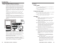
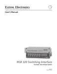
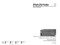
User’s Manual
MAV 62 Composite Video and Audio
MAV 62 S-video and Audio
Matrix Audio and Video
6 Input/2 Output Matrix Switcher
www.extron.com
Extron Electronics, USA
Extron Electronics, Europe
Extron Electronics, Asia
Extron Electronics, Japan
1230 South Lewis Street
Anaheim, CA 92805
USA
714.491.1500
Fax 714.491.1517
Beeldschermweg 6C
3821 AH Amersfoort
The Netherlands
+31.33.453.4040
Fax +31.33.453.4050
135 Joo Seng Road, #04-01
PM Industrial Building
Singapore 368363
+65.6383.4400
Fax +65.6383.4664
Daisan DMJ Building 6F
3-9-1 Kudan Minami
Chiyoda-ku, Tokyo 102-0074 Japan
+81.3.3511.7655
Fax +81.3.3511.7656
© 2003 Extron Electronics. All rights reserved.
68-301-01 Rev. E
Printed in the USA
04 03
Precautions
Safety Instructions • English
This symbol is intended to alert the user of important
operating and maintenance (servicing) instructions
in the literature provided with the equipment.
This symbol is intended to alert the user of the
presence of uninsulated dangerous voltage within
the product's enclosure that may present a risk of
electric shock.
Caution
Read Instructions • Read and understand all safety and operating
instructions before using the equipment.
Retain Instructions • The safety instructions should be kept for future
reference.
Follow Warnings • Follow all warnings and instructions marked on the
equipment or in the user information.
Avoid Attachments • Do not use tools or attachments that are not
recommended by the equipment manufacturer because they may be
hazardous.
Consignes de Sécurité • Français
Ce symbole sert à avertir l’utilisateur que la
documentation fournie avec le matériel contient des
instructions importantes concernant l’exploitation
et la maintenance (réparation).
Ce symbole sert à avertir l’utilisateur de la présence
dans le boîtier de l’appareil de tensions dangereuses
non isolées posant des risques d’électrocution.
Attention
Lire les instructions• Prendre connaissance de toutes les consignes de
sécurité et d’exploitation avant d’utiliser le matériel.
Conserver les instructions• Ranger les consignes de sécurité afin de
pouvoir les consulter à l’avenir.
Respecter les avertissements • Observer tous les avertissements et
consignes marqués sur le matériel ou présentés dans la documentation
utilisateur.
Eviter les pièces de fixation • Ne pas utiliser de pièces de fixation ni
d’outils non recommandés par le fabricant du matériel car cela
risquerait de poser certains dangers.
Sicherheitsanleitungen • Deutsch
Dieses Symbol soll dem Benutzer in der im
Lieferumfang enthaltenen Dokumentation
besonders wichtige Hinweise zur Bedienung und
Wartung (Instandhaltung) geben.
Dieses Symbol soll den Benutzer darauf aufmerksam
machen, daß im Inneren des Gehäuses dieses
Produktes gefährliche Spannungen, die nicht isoliert
sind und die einen elektrischen Schock verursachen
können, herrschen.
Achtung
Lesen der Anleitungen • Bevor Sie das Gerät zum ersten Mal verwenden,
sollten Sie alle Sicherheits-und Bedienungsanleitungen genau
durchlesen und verstehen.
Aufbewahren der Anleitungen • Die Hinweise zur elektrischen Sicherheit
des Produktes sollten Sie aufbewahren, damit Sie im Bedarfsfall darauf
zurückgreifen können.
Befolgen der Warnhinweise • Befolgen Sie alle Warnhinweise und
Anleitungen auf dem Gerät oder in der Benutzerdokumentation.
Keine Zusatzgeräte • Verwenden Sie keine Werkzeuge oder Zusatzgeräte,
die nicht ausdrücklich vom Hersteller empfohlen wurden, da diese eine
Gefahrenquelle darstellen können.
Instrucciones de seguridad • Español
Este símbolo se utiliza para advertir al usuario sobre
instrucciones importantes de operación y
mantenimiento (o cambio de partes) que se desean
destacar en el contenido de la documentación
suministrada con los equipos.
Este símbolo se utiliza para advertir al usuario sobre
la presencia de elementos con voltaje peligroso sin
protección aislante, que puedan encontrarse dentro
de la caja o alojamiento del producto, y que puedan
representar riesgo de electrocución.
Precaucion
Leer las instrucciones • Leer y analizar todas las instrucciones de
operación y seguridad, antes de usar el equipo.
Conservar las instrucciones • Conservar las instrucciones de seguridad
para futura consulta.
Obedecer las advertencias • Todas las advertencias e instrucciones
marcadas en el equipo o en la documentación del usuario, deben ser
obedecidas.
Evitar el uso de accesorios • No usar herramientas o accesorios que no
sean especificamente recomendados por el fabricante, ya que podrian
implicar riesgos.
Extron’s Warranty
Warning
Power sources • This equipment should be operated only from the power source
indicated on the product. This equipment is intended to be used with a main
power system with a grounded (neutral) conductor. The third (grounding) pin is
a safety feature, do not attempt to bypass or disable it.
Power disconnection • To remove power from the equipment safely, remove all
power cords from the rear of the equipment, or the desktop power module (if
detachable), or from the power source receptacle (wall plug).
Power cord protection • Power cords should be routed so that they are not likely to
be stepped on or pinched by items placed upon or against them.
Servicing • Refer all servicing to qualified service personnel. There are no userserviceable parts inside. To prevent the risk of shock, do not attempt to service
this equipment yourself because opening or removing covers may expose you to
dangerous voltage or other hazards.
Slots and openings • If the equipment has slots or holes in the enclosure, these are
provided to prevent overheating of sensitive components inside. These openings
must never be blocked by other objects.
Lithium battery • There is a danger of explosion if battery is incorrectly replaced.
Replace it only with the same or equivalent type recommended by the
manufacturer. Dispose of used batteries according to the manufacturer's
instructions.
Avertissement
Alimentations• Ne faire fonctionner ce matériel qu’avec la source d’alimentation
indiquée sur l’appareil. Ce matériel doit être utilisé avec une alimentation
principale comportant un fil de terre (neutre). Le troisième contact (de mise à la
terre) constitue un dispositif de sécurité : n’essayez pas de la contourner ni de la
désactiver.
Déconnexion de l’alimentation• Pour mettre le matériel hors tension sans danger,
déconnectez tous les cordons d’alimentation de l’arrière de l’appareil ou du
module d’alimentation de bureau (s’il est amovible) ou encore de la prise secteur.
Protection du cordon d’alimentation • Acheminer les cordons d’alimentation de
manière à ce que personne ne risque de marcher dessus et à ce qu’ils ne soient
pas écrasés ou pincés par des objets.
Réparation-maintenance • Faire exécuter toutes les interventions de réparationmaintenance par un technicien qualifié. Aucun des éléments internes ne peut être
réparé par l’utilisateur. Afin d’éviter tout danger d’électrocution, l’utilisateur ne
doit pas essayer de procéder lui-même à ces opérations car l’ouverture ou le
retrait des couvercles risquent de l’exposer à de hautes tensions et autres dangers.
Fentes et orifices • Si le boîtier de l’appareil comporte des fentes ou des orifices,
ceux-ci servent à empêcher les composants internes sensibles de surchauffer. Ces
ouvertures ne doivent jamais être bloquées par des objets.
Lithium Batterie • Il a danger d'explosion s'll y a remplacment incorrect de la
batterie. Remplacer uniquement avec une batterie du meme type ou d'un ype
equivalent recommande par le constructeur. Mettre au reut les batteries usagees
conformement aux instructions du fabricant.
Vorsicht
Stromquellen • Dieses Gerät sollte nur über die auf dem Produkt angegebene
Stromquelle betrieben werden. Dieses Gerät wurde für eine Verwendung mit
einer Hauptstromleitung mit einem geerdeten (neutralen) Leiter konzipiert. Der
dritte Kontakt ist für einen Erdanschluß, und stellt eine Sicherheitsfunktion dar.
Diese sollte nicht umgangen oder außer Betrieb gesetzt werden.
Stromunterbrechung • Um das Gerät auf sichere Weise vom Netz zu trennen,
sollten Sie alle Netzkabel aus der Rückseite des Gerätes, aus der externen
Stomversorgung (falls dies möglich ist) oder aus der Wandsteckdose ziehen.
Schutz des Netzkabels • Netzkabel sollten stets so verlegt werden, daß sie nicht
im Weg liegen und niemand darauf treten kann oder Objekte darauf- oder
unmittelbar dagegengestellt werden können.
Wartung • Alle Wartungsmaßnahmen sollten nur von qualifiziertem
Servicepersonal durchgeführt werden. Die internen Komponenten des Gerätes
sind wartungsfrei. Zur Vermeidung eines elektrischen Schocks versuchen Sie in
keinem Fall, dieses Gerät selbst öffnen, da beim Entfernen der Abdeckungen die
Gefahr eines elektrischen Schlags und/oder andere Gefahren bestehen.
Schlitze und Öffnungen • Wenn das Gerät Schlitze oder Löcher im Gehäuse
aufweist, dienen diese zur Vermeidung einer Überhitzung der empfindlichen
Teile im Inneren. Diese Öffnungen dürfen niemals von anderen Objekten
blockiert werden.
Litium-Batterie • Explosionsgefahr, falls die Batterie nicht richtig ersetzt wird.
Ersetzen Sie verbrauchte Batterien nur durch den gleichen oder einen
vergleichbaren Batterietyp, der auch vom Hersteller empfohlen wird. Entsorgen
Sie verbrauchte Batterien bitte gemäß den Herstelleranweisungen.
Advertencia
Alimentación eléctrica • Este equipo debe conectarse únicamente a la fuente/tipo
de alimentación eléctrica indicada en el mismo. La alimentación eléctrica de este
equipo debe provenir de un sistema de distribución general con conductor
neutro a tierra. La tercera pata (puesta a tierra) es una medida de seguridad, no
puentearia ni eliminaria.
Desconexión de alimentación eléctrica • Para desconectar con seguridad la
acometida de alimentación eléctrica al equipo, desenchufar todos los cables de
alimentación en el panel trasero del equipo, o desenchufar el módulo de
alimentación (si fuera independiente), o desenchufar el cable del receptáculo de
la pared.
Protección del cables de alimentación • Los cables de alimentación eléctrica se
deben instalar en lugares donde no sean pisados ni apretados por objetos que se
puedan apoyar sobre ellos.
Reparaciones/mantenimiento • Solicitar siempre los servicios técnicos de personal
calificado. En el interior no hay partes a las que el usuario deba acceder. Para
evitar riesgo de electrocución, no intentar personalmente la reparación/
mantenimiento de este equipo, ya que al abrir o extraer las tapas puede quedar
expuesto a voltajes peligrosos u otros riesgos.
Ranuras y aberturas • Si el equipo posee ranuras o orificios en su caja/alojamiento,
es para evitar el sobrecalientamiento de componentes internos sensibles. Estas
aberturas nunca se deben obstruir con otros objetos.
Batería de litio • Existe riesgo de explosión si esta batería se coloca en la posición
incorrecta. Cambiar esta batería únicamente con el mismo tipo (o su equivalente)
recomendado por el fabricante. Desachar las baterías usadas siguiendo las
instrucciones del fabricante.
Extron Electronics warrants this product against defects in materials and workmanship for a
period of three years from the date of purchase. In the event of malfunction during the warranty
period attributable directly to faulty workmanship and/or materials, Extron Electronics will, at its
option, repair or replace said products or components, to whatever extent it shall deem necessary
to restore said product to proper operating condition, provided that it is returned within the
warranty period, with proof of purchase and description of malfunction to:
USA, Canada, South America,
and Central America:
Extron Electronics
1230 South Lewis Street
Anaheim, CA 92805, USA
Asia:
Extron Electronics, Asia
135 Joo Seng Road, #04-01
PM Industrial Bldg.
Singapore 368363
Europe, Africa, and the Middle East:
Extron Electronics, Europe
Beeldschermweg 6C
3821 AH Amersfoort
The Netherlands
Japan:
Extron Electronics, Japan
Daisan DMJ Bldg. 6F,
3-9-1 Kudan Minami
Chiyoda-ku, Tokyo 102-0074
Japan
This Limited Warranty does not apply if the fault has been caused by misuse, improper handling
care, electrical or mechanical abuse, abnormal operating conditions or non-Extron authorized
modification to the product.
If it has been determined that the product is defective, please call Extron and ask for an
Applications Engineer at (714) 491-1500 (USA), 31.33.453.4040 (Europe), 65.6383.4400
(Asia), or 81.3.3511.7655 (Japan) to receive an RA# (Return Authorization number). This
will begin the repair process as quickly as possible.
Units must be returned insured, with shipping charges prepaid. If not insured, you assume the
risk of loss or damage during shipment. Returned units must include the serial number and a
description of the problem, as well as the name of the person to contact in case there are any
questions.
Extron Electronics makes no further warranties either expressed or implied with respect to the
product and its quality, performance, merchantability, or fitness for any particular use. In no
event will Extron Electronics be liable for direct, indirect, or consequential damages resulting
from any defect in this product even if Extron Electronics has been advised of such damage.
Please note that laws vary from state to state and country to country, and that some provisions of
this warranty may not apply to you.
Table of Contents
Chapter 1 • Introduction .......................................................... 1-1
About the MAV 62 Matrix Switchers .......................... 1-2
Features ...................................................................................... 1-3
S-video model ........................................................................ 1-3
Composite video model ........................................................ 1-3
All models .............................................................................. 1-3
Chapter 2 • Installation ............................................................. 2-1
Installation Overview .......................................................... 2-2
Mounting the switcher ....................................................... 2-2
Rear Panel Cabling ................................................................ 2-2
Signal input connections ....................................................... 2-2
Signal output connections .................................................... 2-5
RS-232 connection ................................................................. 2-6
External sync connection ....................................................... 2-6
Power connection .................................................................. 2-7
Chapter 3 • Operation ................................................................ 3-1
Front Panel Controls and Indicators ............................ 3-2
Front Panel Operations ....................................................... 3-3
Creating ties ........................................................................... 3-3
Audio gain and attenuation ................................................. 3-4
Viewing and adjusting an audio level .................................. 3-5
Audio level reset .................................................................... 3-6
Memory ...................................................................................... 3-6
Troubleshooting — if no image appears ................... 3-6
Chapter 4 • RS-232/Remote Control ................................. 4-1
Simple Instruction Set Control ....................................... 4-2
Host-to-interface communications ....................................... 4-2
Switcher-initiated messages .................................................. 4-2
Error responses ...................................................................... 4-3
Timeout .................................................................................. 4-3
Using the command/response table ..................................... 4-3
Symbol definitions ................................................................. 4-4
Windows-Based Program Control ................................. 4-4
Installing the software .......................................................... 4-4
Using the software ................................................................ 4-6
Using the help system ........................................................... 4-6
MAV 62 Matrix Switcher• Table of Contents
i
Table of Contents, cont’d
Appendix A • Specifications,
Accessories, and Part Numbers ........ A-1
Specifications ......................................................................... A-2
Included Parts ......................................................................... A-4
Accessories ............................................................................... A-5
Cables ......................................................................................... A-5
MAV 62 Matrix Switcher
1
Chapter One
Introduction
About the MAV 62 Matrix Switchers
Features
68-301-01 Rev. E
Printed in the USA
04 03
All trademarks mentioned in this manual are the properties of their respective
owners.
ii
MAV 62 Matrix Switcher • Table of Contents
Introduction, cont’d
Introduction
About the MAV 62 Matrix Switchers
Features
The Extron MAV 62 family of matrix switchers consists of two
models of 6-input, 2-output audio and video matrix switchers;
the MAV 62 composite matrix routes composite video and the
MAV 62 S-video matrix routes S-video. Both models route
balanced or unbalanced stereo audio. The MAV 62 switchers
distribute any of six video and/or audio inputs to either output
or to both outputs. Any input can be switched to either or both
outputs.
The switchers are compatible with NTSC 3.38 and 4.43, PAL,
and SECAM video. When external sync is applied, video
switching occurs during the vertical interval, providing glitchfree switching.
The switchers allow the user to switch between devices, such as
a DSS receiver, a VHS or S-VHS VCR, a DVD player, or a
camcorder, and output the image to one or two video recorders
or displays, such as a data monitor or large screen projector
(figure 1-1).
RS-232 control
100-240VAC 50/60Hz
REMOTE
0.35A MAX
MAV 62
VCR
Laserdisc player
DVD player
DSS receiver
DVD player
Monitor
Video camera
LCD projector
Figure 1-1 — Typical MAV 62 switcher application
The audio switching can either be linked with the video (audio
follow) or independent of the video (audio breakaway).
Adjustable audio gain and attenuation compensates for level
differences between audio inputs.
The ½-rack width switcher can be mounted to a standard Extron
rack panel (part # 60-190-01). Each model has an internal
100VAC to 240VAC, 50/60 Hz, 15 watts, auto-switchable power
supply that provides worldwide power compatibility.
1-2
MAV 62 Matrix Switcher • Introduction
S-video model
Inputs — S-video switchers accept up to six S-video inputs on
4-pin mini DIN connectors.
Outputs — S-video switchers output two S-video signals on 4pin mini DIN connectors.
Composite video model
Inputs — Composite video switchers accept up to six composite
video inputs on BNC female connectors.
Outputs — Composite video switchers output two composite
video signals on BNC female connectors.
All models
Audio inputs — Audio switchers accept up to six stereo audio
inputs, balanced or unbalanced, on 3.5 mm, 5-pole
captive screw terminals.
Audio outputs — Audio switchers output two stereo audio
outputs, balanced or unbalanced, on 3.5 mm, 5-pole
captive screw terminals.
Audio input gain and attenuation — Users can set the level of
audio gain or attenuation (-15dB to +9dB) for each input
via the RS-232 link or from the front panel. Individual
input audio levels can be adjusted so there are no
noticeable volume differences between sources.
Front panel control — The operator can select the inputs and
outputs and set the audio gain and attenuation for each
input using the front panel buttons.
RS-232 control — The operator can control the MAV 62 from a
remote computer or other host using an RS-232 link on
the Remote port. RS-232 control uses Extron’s Simple
Instruction Set™ (SIS™) or the Windows®-based control
software.
Simple Instruction Set — The Simple Instruction Set
program lets a host computer control the MAV 62
with simple commands.
Windows control software — Extron’s Windows-based
control software provides a graphic way to set up
and control the MAV 62 with an on-screen control
panel. It allows the operator to remotely select
inputs, make audio adjustments, and store settings
for future use.
MAV 62 Matrix Switcher • Introduction
1-3
Introduction, cont’d
Rack mount option — The MAV 62 is 1U high and a half-rack
width wide. It can be installed on a standard rack shelf
using an Extron 1U Shelf Rack, part # 60-190-01.
Auto-switching power supply — An internal power supply
with an IEC connector makes power cord connection
easy. The power supply can be used internationally with
any power input from 110 VAC to 240 VAC at 50 or 60 Hz
and adapts automatically to the input type.
MAV 62 Matrix Switcher
2
Chapter Two
Installation
Installation Overview
Mounting the switcher
Rear Panel Cabling
1-4
MAV 62 Matrix Switcher • Introduction
Installation, cont’d
Installation
Installation Overview
To install and set up an Extron MAV 62 switcher for operation,
follow these steps:
1
Turn off all of the equipment. Ensure that the video
sources (DVD players, laserdisc players, VCRs, satellite
receivers, or other devices) and the output display are all
turned off and disconnected from the power source.
2
Mount the switcher. See Mounting the switcher in this
chapter.
3
Attach the cables. See Rear Panel Cabling in this chapter.
4
Connect power cords and turn on the display devices and
the input devices.
5
Set the audio gain and attenuation. See Front Panel
Controls and Indicators in chapter 3.
False Front panel
uses 2 front holes
(2) 4-40 x 3/16" Screws
MA
V 62
6x
Mounting the switcher
1.
2 S-V S-VI
IDE DE
O
O
AN AN
D AU D
AU
DIO
DI
MA O
TR
IX
Use 2 mounting holes on
opposite corners
For optional rack mounting, mount the MAV switcher on
the left or right side of a 19" 1U Universal Rack Shelf
(Extron part #60-190-01) (figure 2-1).
a.
If feet were previously installed on the bottom of the
case, remove them.
b.
Mount the switcher on the rack shelf, using two
4-40 x 3/16 screws in opposite (diagonal) corners to
secure the case to the shelf.
2.
If desired, attach a false front panel, or a second ½-rackwidth device to the other side of the shelf.
3.
Attach the rack shelf to the rack using four 10-32 x ¾” bolts
and four #10 beveled dress washers.
Figure 2-1 — Rack mounting the switcher
1
7
Rear Panel Cabling
3
2
6
4
5
Figure 2-2 — MAV 62 S-video cabling
All connectors are on the rear panel. Depending on the model
of the switcher, the type and layout of the connectors on the rear
panel will vary. Figure 2-2 shows the rear panel of the MAV 62
S-video switcher. Figure 2-3 shows the rear panel of the MAV 62
composite switcher.
1
3
6
Signal input connections
1
S-video input connectors — Connect S-video sources to these
4-pin mini DIN connectors.
7
2
4
5
Figure 2-3 — MAV 62 composite video cabling
2-2
MAV 62 Matrix Switcher • Installation
MAV 62 Matrix Switcher • Installation
2-3
Installation, cont’d
Composite video input connectors — Connect composite video
sources to these female BNC connectors.
Tip (L)
Ring (R)
Tip (+)
The MAV 62 switchers do not alter the video signal in
any way. The signal output by the switcher is in the
same format as the input.
2
Connections for balanced and unbalanced audio inputs —
Each input has a 3.5 mm, 5-pole captive
screw connector for balanced or
unbalanced stereo audio input.
Connectors are included with each MAV
switcher, but you must supply the audio
cable. See figure 2-4 to wire a connector
for the appropriate input type and
impedance level. High impedance is
generally over 800 ohms.
CAUTION
The captive screw connector can easily be
inadvertently plugged partially into one receptacle
and partially into an adjacent receptacle. This
misconnection could damage the audio output
circuits. Exercise care to ensure the captive screw
connector is plugged into the desired input or
output.
600 ohms
Tip
Ring
Sleeve (s)
Tip
Ring
Tip
Sleeve
Tip
Sleeve
Tip
Ring
Sleeve (s)
Tip
Ring
Sleeve ( )
Sleeve ( )
RCA Connector
3.5 mm Stereo Plug Connector
(unbalanced)
Figure 2-5 — Phono audio connectors
Signal output connections
3
S-video output connectors — Connect S-video displays to these
two 4-pin mini DIN connectors.
Composite video output connectors — Connect composite
video displays to these two female BNC connectors.
4
Connections for audio outputs — These 3.5 mm, 5-pole captive
screw connectors output the selected unamplified, line level
audio. Connect audio devices, such as an amplifier or powered
speakers. See figure 2-6 to properly wire an output connector.
Tip
Ring
Sleeve (s)
Tip
Ring
Tip
See caution
Sleeve
Tip
See caution
Unbalanced Output
Balanced Output
600 ohms
Unbalanced Input
Balanced Input
Balanced Input
(high impedance)
(high impedance)
(600 ohms)
Figure 2-4 — Captive screw connector wiring for
input
When making connections for the switcher from existing
audio cables, see figure 2-5. A mono audio connector
consists of the tip and sleeve. A stereo audio connector
consists of the tip, ring and sleeve. The ring, tip, and
sleeve wires are also shown on the captive screw audio
connector diagrams, figure 2-4 and figure 2-6.
Figure 2-6 — Captive screw connector wiring for
audio output
CAUTION
Connect the sleeve to ground (Gnd). Connecting
the sleeve to a negative (-) terminal will damage the
audio output circuits.
By default, the audio output follows the video switch. Audio
breakaway, commanded via the RS-232 link, allows the user to
select from any one of the audio input sources. See chapter 4,
RS-232/Remote Control for details on the RS-232 connection
The audio level for each input can be individually set, via the
front panel or RS-232, to ensure that the level on the output does
not vary from input to input. See chapter 3, Operation, and
chapter 4, RS-232/Remote Control, for details.
2-4
MAV 62 Matrix Switcher • Installation
MAV 62 Matrix Switcher • Installation
2-5
Installation, cont’d
RS-232 connection
5
Timing source
OUT
Remote connector — Connect a host device, such as a computer
or a touch control panel,
to the MAV switcher via
5
1
1
5
this 9-pin D connector
for remote control using
9
6
6
9
the Simple Instruction
Female
Male
Set (SIS) or the Extron
graphical control
program for Windows.
IN
To next device
or terminate
MAV 62 rear panel
Figure 2-7 —Simple external sync connection
example
See chapter 4, RS-232/Remote Control, for definitions of the SIS
commands and details on how to install and use the control
software.
VCR
External sync connection
When switching between inputs, the resulting image change
should be seamless, or clean. The MAV switchers can use an
external signal to synchronize switching during the vertical
interval. Without the external sync locking feature, switching
between inputs can result in a brief rolling (sync loss) or a brief
change in the picture size.
VGA Input
Extron
VSC 700
Monitor
R
FIE
PLI
N AM
TIO
BU
TRI
DIS
Scan Converter
IN
SDI
OUT
B/B-Y
O
G/Y
S-VIDE
VID
R/R-Y
H
V
B
CK
RS-232
/422
GENLO
V
V
H
Extron
BBG 6 A
S
OUTPUT
H
G
B
R
G
0.3A
R
100-240V
INPUTS
Hz
50/60
OUT
IN
B
NC
SY
A
Blackburst/
Audio Generator
S
UT
TP
OU
R
B
L
A
L
R
S
R
UT
TP
OU
6
L
R
S
UT
INP
5
L
R
4
L
3
L
S
R
UT
INP
R
2
L
R
1
6
L
External Sync In connector — Connect an external sync signal
to this BNC connection for genlocking the video signal in
broadcast or other sync-critical applications.
Extron
MAV 62 S-Video & Audio
Matrix Switcher
External Sync Out connector — Connect any downstream
equipment that requires genlocking to this BNC connector to
route the external sync signal throughout the system in
broadcast or other sync-critical applications.
Video Camera
Figure 2-7 shows a basic external sync configuration. The Ext
Sync In connector receives a timing signal. The Ext Sync Out
connector allows the signal to be passed on to another video
device, if required.
Figure 2-8 shows a typical configuration in which the timing
source passes through three video cameras and a video scan
converter before connecting to the switcher. This type of video
camera is capable of synchronizing with the external timing
source for video editing applications.
Video Camera
Video Camera
Figure 2-8 — Multiple device external sync
connection example
Power connection
7
AC power connector — Plug a standard IEC power cord into
this connector to connect the switcher to a 100 to 240VAC, 50 Hz
or 60 Hz power source.
If no external sync timing source is connected to the switcher,
switching occurs immediately.
2-6
MAV 62 Matrix Switcher • Installation
MAV 62 Matrix Switcher • Installation
2-7
Installation, cont’d
MAV 62 Matrix Switcher
3
Chapter Three
Operation
Front Panel Controls and Indicators
Front Panel Operations
Memory
Troubleshooting — If no image appears
2-8
MAV 62 Matrix Switcher • Installation
Operation, cont’d
Operation
Front Panel Controls and Indicators
1
Figure 3-1 shows the controls and indicators on the front panel
of the MAV 62 switcher.
2
on
on
off
on
MAV 62 S-VIDEO AND AUDIO
6 x 2 S-VIDEO AND AUDIO MATRIX
on
off
MAV 62 S-VIDEO AND AUDIO
Figure 3-2 — Video and/or audio selection
6 x 2 S-VIDEO AND AUDIO MATRIX
1
2
3
4
5
Figure 3-1 — MAV 62 controls and indicators
1
2
3
Power LED — The Power LED lights to indicate power is on. If
AC voltage is available, power is on. When power is first
applied, all front panel LEDs flash to indicate that the power up
sequence was accomplished satisfactorily.
Outputs button and LED — The Outputs button toggles
between output 1 and output 2. The Outputs LED indicates the
selected output.
Input buttons and LEDs — The input 1 through input 6 buttons
select an input for output. The input 1 through input 6 LEDs
indicate the selected input.
As a secondary function, the input 5/ and input 6/ buttons
increase and decrease the amount of audio gain for a selected
input and the input 1 through 5 LEDs indicate the audio level of
the selected input. See Audio gain and attenuation in this chapter.
4
I/O configuration/save button and LED — The I/O Conf/Save
button has two functions, selecting between video and audio
and selection of audio gain and attenuation mode. The I/O
LED identifies which function is selected.
Video and/or audio selection — When pressed and released,
the I/O button cycles through video and audio, audio only, and
video only selected for configuration (figure 3-2). The I/O LED
is off when this function is enabled, and the Video/+dB and
Audio/-dB LEDs (5) report the video and audio input selection.
Audio gain and attenuation mode — When pressed and held,
the I/O button selects or deselects audio gain and attenuation
mode, in which the operator can adjust the audio gain and
attenuation. The I/O LED blinks when this function is enabled,
and the Video/+dB and Audio/-dB LEDs are part of the audio
level display for the selected input. See Audio gain and
attenuation in this chapter.
3-2
MAV 62 Matrix Switcher • Operation
5
Video/+dB and Audio/-dB LEDs — The function of the Video/
+dB and Audio/-dB LEDs varies depending on whether the
I/O Conf/Save button is selecting between video and audio or
if the switcher is in audio gain and adjustment mode.
Video and/or audio selection — The Video/+dB and Audio/
-dB LEDs indicate whether video, audio, or both are selected for
display and/or selection. If audio is broken away and video
and audio are selected for display, the Audio/-dB LED blinks.
Audio gain and attenuation mode — The Video/+dB and
Audio/-dB LEDs indicate the polarity of the audio level setting.
See Audio gain and attenuation in this chapter.
Front Panel Operations
Plug in all system components and turn on the input devices
(such as DVD players, laserdisc players, VCRs, and DSS
receivers) and the output devices. Set the input devices to
output video using each device’s own operating instructions.
Creating ties
A Tie is an input-to-output connection. An input can be tied to
both outputs. (An output can never be tied to more than one
input.)
Create video and/or audio ties using the front panel buttons as
follows:
You cannot create a tie from the front panel if the
MAV 62 is in audio gain and attenuation mode (if the
I/O LED is blinking). If the I/O LED is blinking, press
and hold the I/O Conf/Save button until the I/O LED
goes out.
1.
Press and release the Outputs button to select the desired
output. The LED for the selected output lights.
2.
Press and release the I/O Conf/Save button as necessary
to select either video and audio (audio follow) or video or
audio (audio breakaway).
MAV 62 Matrix Switcher • Operation
3-3
Operation, cont’d
3.
Press and release the button for the desired input. The
LED for the selected input lights.
If audio and video are tied from different inputs (audio
breakaway), and if you select video and audio for display,
the Video/+dB LED and the LED for the selected video
input light steadily and the Audio/-dB LED and the
LED for the selected audio input blink (figure 3-3).
Key:
B = blinking,
3.
Press and release the
and
decrease the audio level.
4.
Press and hold the I/O Conf/Save button until the I/O
LED turns off to save the gain value in memory and exit
the audio display and adjustment mode.
B
= on
B
Figure 3-3 — Audio
breakaway indication
Key:
Audio gain and attenuation
The audio level of each input can
be displayed and adjusted, from
the front panel or by using Extron’s
Windows-based control program,
through a range of -15dB to +9dB to
ensure that there is no noticeable
volume difference among sources.
1.
Press and release an input
button to select an input.
2.
Press and hold the I/O Conf/
Save button until the I/O LED
begins to blink, then release
the button. The input 1
through 5 LEDs display the
audio level for the selected
input and the Video/+dB and
Audio/-dB LEDs display the
polarity (+ or -).
Each input LED indicates 0dB
when off, 1dB when blinking
slowly, 2dB when blinking
quickly, and 3dB when lit.
The Video/+dB LED indicates
a positive (gain) level. The
Audio/-dB LED indicates a
negative (attenuation) level.
Both LEDs on indicate 0dB.
3-4
MAV 62 Matrix Switcher • Operation
There is one audio level setting per input. The
setting is shared by the left and right audio inputs.
2.
The audio level settings are stored in non-volatile
memory. When power is removed and restored, the
audio level settings are retained.
Viewing and adjusting an audio level
See figure 3-4 and figure 3-5 and the following steps for an
example of viewing and adjusting the audio level on a MAV 62
switcher.
B2 = fast blink (value 2dB),
= on (value 3dB)
dB
1.
= off (value 0 dB),
B1 = slow blink (value 1dB),
A tie can also be created by an
RS-232 device (see chapter 4,
RS-232/Remote Control).
buttons to increase and
1
Input LED
2
3
4
-dB +dB
C
B2
5
+9
+8
B2
+7
B1
A
+6
+5
B2
+4
B1
+3
+2
B2
+1
B1
+8dB
LED key:
= off (value 0 dB), B1 = slow blink (value 1dB),
B2 = fast blink (value 2dB),
0
B2
= on (value 3dB)
B
-1
B1
-2
B2
CONF./SAVE
Figure 3-4 — Viewing the audio level
-3
-4
B1
-5
B2
A
Press and release an input button to select an input. The
associated input LED lights.
B
Press and hold the I/O Conf/Save button until the I/O LED
starts blinking.
C
The input 1 through 5 LEDs display the gain or attenuation
value. The Video/+dB and Audio/-dB LEDs display the
polarity. In Figure 3-4, the value +8dB is displayed.
-6
-7
B1
-8
B2
-9
-10
B1
-11
B2
-12
D
-13
B1
-14
B2
-15
Press and release the
button several times to decrease the
audio level displayed in the input LEDs by 1dB per button
push. Note the input LED, Video/+dB LED, and audio/-dB
LED changes that occur each time the
button is pressed and
released. Figure 3-5 shows the result of pressing the
button a
MAV 62 Matrix Switcher • Operation
3-5
Operation, cont’d
total of nine times to change the value to -1dB. Note that the
Video/+dB LED has turned off and that the Audio/-dB LED is
on to indicate a negative level.
E
D
E
D
B1
-1dB
LED key:
D
= off (value 0 dB),
B1 = slow blink (value 1dB),
CONF./SAVE
B2 = fast blink (value 2dB),
E
= on (value 3dB)
CONF./SAVE
Figure 3-5 — Adjusting the audio level
E
Press and hold the Audio button until the Audio LED turns off.
The Video/+dB and Audio/-dB LEDs display video and/or
audio selected, and the selected input and output LEDs light.
Audio level reset
To reset the audio level to 0dB for all inputs, press and hold the
Audio button for approximately 10 seconds. The Audio LED
begins to blink and then turns off. Release the Audio button.
4
Chapter Four
RS-232/Remote Control
Memory
Audio settings are saved in nonvolatile memory. When the
switcher is powered off, the settings are retained. When the
switcher is powered on, the saved settings are active. The ties
are not saved; when the switcher is powered on it defaults to
input 1 tied to output 1 and input 2 tied to output 2.
Troubleshooting — If no image appears
3-6
MAV 62 Matrix Switcher
1.
Ensure that all devices are plugged in and powered on.
The switcher is receiving power if the Power LED is lit.
2.
Ensure an active input and output are selected on the
MAV 62.
3.
Ensure that the proper signal format is supplied.
4.
Check the cabling and make corrections as necessary.
5.
Call the Extron S3 Sales & Technical Support Hotline if
necessary.
MAV 62 Matrix Switcher • Operation
Simple Instruction Set Control
Windows-Based Program Control
RS-232/Remote Control,
Control cont’d
The switcher’s rear panel Remote connector (figure 4-1) can be
connected to the serial port output of a host device. Remote
communications with the switcher are via Extron’s Simple
Instruction Set or using Extron’s Windows-based control
program.
1
5
6
9
Male
5
1
9
6
Female
Pin
RS-232
1
—
2
3
TX
X
RX
4
5
6
—
Gnd
7
8
9
Function
Transmit data
Receive data
Ground
—
—
—
—
All is both video and audio (the power-up default is video and
audio output 1 tied to input 1 and video and audio output 2 tied
to input 2). The switcher also sends the Outx Inn message
whenever the selected input is changed using the front panel
buttons.
Reconfig
The switcher initiates this message when there is a change in the
audio gain setting for any input.
Error responses
When the switcher receives a valid SIS command, it executes the
command and sends a response to the host device. If the
switcher is unable to execute the command because the
command is invalid or it contains invalid parameters, the
switcher returns an error response to the host. The error
response codes are:
Figure 4-1 — Remote connector pinout
E01
- Invalid input channel number (out of range)
E10
- Invalid command
E12
The RS-232 protocol of the rear panel RS-232/Remote connector
is 9600 baud, 1 stop bit, no parity, and no flow control.
Simple Instruction Set Control
Host-to-interface communications
SIS commands consist of one or more characters per field. No
special characters are required to begin or end a command
character sequence. When a command is valid, the switcher
executes the command and sends a response to the host device.
All responses from the switcher to the host end with a carriage
return and a line feed (CR/LF = ), which signals the end of
the response character string. A string is one or more characters.
Switcher-initiated messages
E13
Invalid output number (out of range)
- Invalid gain value (out of range)
Timeout
Pauses of 10 seconds or longer between command ASCII
characters result in a timeout. The command operation is
aborted with no other indication.
Using the command/response table
The command/response table is on the next page. Lower case
letters are allowed in the command field only as indicated.
Symbols are used throughout the table to represent variables in
the command/response fields. Command and response
examples are shown throughout the table. The ASCII to HEX
conversion table is for use with the command/response table.
When a local event, such as a front panel operation or error
condition, occurs, the switcher responds by sending a message
to the host. The switcher-initiated messages are listed below:
(C) Copyright 1996, Extron Electronics MAV 62, Vx.xx
Out1 Inn All
Out2 Inn All
The switcher issues the copyright message and the input
selected message when it first powers on. Vx.xx is the firmware
version number. Outx Inn All identifies the currently selected
ties, where x is the output number, n is the input number, and
4-2
MAV 62 Matrix Switcher • RS-232/Remote Control
MAV 62 Matrix Switcher • RS-232/Remote Control
4-3
The program is contained on a single 3.5” diskette and can be
run from the floppy drive, or it can be installed and run from
the hard drive. To install the software on the hard drive, run
setup.exe from the floppy disk and follow the screen
instructions.
By default, the Windows installation creates a C:\UNIVSW
folder and places two icons (Universal Switcher Control
Program and Universal Switcher Help) into a group named
“Extron Electronics”.
4-4
MAV 62 Matrix Switcher • RS-232/Remote Control
60-419-01 = MAV 62 S-video.
N60-570-01
QVER X6
N/n
Q/q
Installing the software
Request for part number
Query software version
Updates to this program can be downloaded from the Extron
Web site (http://www.extron.com).
V X1 G
V4G
I/i
I
The Universal Switcher Control Program is compatible with
Windows 3.1/3.11, Windows 95/98, Windows NT, Windows
ME, and Windows 2000 and provides remote control of the
input selection for each output (including audio breakaway)
and audio gain and attenuation adjustments.
Command/response table for SIS commands
Windows-Based Program Control
View gain or attenuation
Example
Information request
Example
ASCII to HEX Conversion Table
Space
View, information, part number, and firmware requests
x.xx
to
= Software version
X1
X6
Set attenuation for input
Numeric dB value, –15 to +9
IN X1 •AUD= X5
= Gain/attenuation value
X1 * X4 g
X5
Set attenuation
16 steps ±1dB per step
Set gain for input X1 to X4 dB.
Set gain for input 4 to 3dB.
= Gain/attenuation value
IN X1 •AUD= X4
IN4•AUD=3
X4
X1 * X4 G
4*3G
0 through 6 (0 = muted
output)
Input audio gain and attenuation
= Input number
OUT X2 IN X3 ALL
OUT2IN5 ALL
OUT X2 IN X3 VID
OUT X2 IN X3 AUD
X3
X3 * X2 !
5*2!
X3 * X2 &
X3 * X2 $
1 or 2
Select video/audio input
Example:
Select video input only
Select audio input only
= Output number
Input selection
X2
(switcher to host)
1 through 6
ASCII Command Response
= Input number
(host to switcher)
X1
Additional description
= space
Command
•
Set gain
Example:
= CR/LF (carriage return/line feed) (0x0D 0A)
X4 dB.
Tie input X3 video and audio to output X2 .
Tie input 5 video and audio to output 2.
Tie input X3 video to output X2 (audio breakaway).
Tie input X3 audio to output X2 (audio breakaway).
Symbol definitions
IN X1 •AUD= X5
View gain for input X1 .
IN4•AUD=-3
Attenuation for input 4 is set to -3dB.
V1* X1 •A1* X1 •V2* X1 •A2* X1 •QVER X6
V1*1•A1*1•V2*2•A2*2•QVER1.23
Video input 1 tied to output 1; audio input 1 tied to
output 1; video input 2 tied to output 2; audio input
2 tied to output 2; software version 1.23.
RS-232/Remote Control, cont’d
MAV 62 Matrix Switcher • RS-232/Remote Control
4-5
RS-232/Remote Control, cont’d
Using the software
1.
To run the software, double click on the Universal
Switcher Control Program icon in the Extron
Electronics program group.
2.
Click on the comm port that is connected to
the MAV 62’s RS-232 port.
3.
The Extron Universal Switcher Control
Program window (figure 4-2) displays the
selected inputs for each output and the audio
gain for the selected audio inputs.
Using the help system
For information about program features, you can access the help
program in any of the following ways:
• From the Extron Electronics program group, double-click on
the Signal Enhancement Products Help icon.
• From within the Windows-based switcher
control program, click on the Help entry on
the task bar.
• From within the Windows-based switcher
control program, press the F1 key.
MAV 62 Matrix Switcher
A
Appendix A
Specifications,
Accessories, and Part Numbers
Specifications
Included Parts
Accessories
Cables
Figure 4-2 — Universal Switcher Control Program
window
4-6
MAV 62 Matrix Switcher • RS-232/Remote Control
Specifications, cont’d
Specifications
Video
Routing .......................................... 6 x 2 matrix
Gain ............................................... Unity
Bandwidth .................................... 150 MHz (-3dB), fully loaded
0 - 10 MHz ................. no more than 0.1dB
to -0.1dB
0 - 30 MHz ................. no more than 0.5dB
to -0.5dB
Phase between I/Os .................... <1.28º at 3.58 MHz
Differential phase error .............. 0.1% at 3.58 MHz and 4.43 MHz
Differential gain error ................. 0.1º at 3.58 MHz and 4.43 MHz
Max. propagation of delay ......... 5 ns typical (±1 ns)
Crosstalk ....................................... -50dB @ 5 MHz
Switching speed ........................... 200 ns (max.)
Video input
Number/signal type
MAV 62 Composite Video
MAV 62 S-video ...............
Connectors
MAV 62 Composite Video
MAV 62 S-video ...............
Nominal level ...............................
Minimum/maximum levels ......
Impedance ....................................
Return loss ....................................
Maximum DC offset ....................
External sync (genlock) ...............
6 composite video
6 S-video
6 BNC female
(6) 4-pin mini DIN female
1V p-p for S-video, and for composite video
0.3V p-p for C of S-video
Analog: 0.5V to 2.0V p-p with no offset
75 ohms
<-30dB @ 5 MHz
1.5V
0.3V to 0.4V p-p
Video output
Number/signal type
MAV 62 Composite Video
MAV 62 S-video ...............
Connectors
MAV 62 Composite Video
MAV 62 S-video ...............
Nominal level ...............................
Sync
Genlock connectors ..................... 2 BNC female
Standards ...................................... NTSC 3.58, NTSC 4.43, PAL, SECAM
Audio
Routing .......................................... 6 x 2 stereo matrix
Gain ............................................... Unbalanced output: 0dB; balanced output:
+6dB
Frequency response ..................... 20 Hz to 20 kHz, ±0.05dB
THD + Noise ................................ 0.03% @ 1 kHz at rated nominal level
S/N ................................................ >90dB, output 21dBu, balanced, at rated
maximum output
Crosstalk ....................................... <-80dB @ 1 kHz, fully loaded
Stereo channel separation .......... >80dB @ 1 kHz
CMRR ............................................ >75dB @ 20 Hz to 20 kHz
Audio input
Number/signal type ................... 6 stereo, balanced/unbalanced
Connectors .................................... (6) 3.5 mm captive screw connectors, 5
pole
Impedance .................................... >10 kohms unbalanced/balanced, DC
coupled
Nominal level ............................... -10dBV (316mV)
Maximum level ............................ +19.5dBu, (balanced or unbalanced) at
1%THD+N
Input gain adjustment ................. -15dB to +9dB, adjustable per input via
RS-232/422 or front panel
Audio output
2 composite video
2 S-video
2 BNC female
(2) 4-pin mini DIN female
1V p-p for S-video, and for composite video
0.3V p-p for C of S-video
Minimum/maximum levels ...... 0.5V to 2V p-p
Impedance .................................... 75 ohms
Return loss .................................... -30dB @ 5 MHz
A-2
DC offset ....................................... ±5mV maximum with input at 0 offset
Switching type ............................. Vertical interval
MAV 62 Matrix Switcher • Specifications
Number/signal type ................... 2 stereo, balanced/unbalanced
Connectors .................................... (2) 3.5 mm captive screw connectors, 5
pole
Impedance .................................... 50 ohms unbalanced, 100 ohms balanced
Gain error ...................................... ±0.1dB channel to channel
Maximum level (Hi-Z) ................ >+21dBu, balanced or unbalanced at
stated %THD+N
Maximum level (600 ohm) ......... >+15dBm, balanced or unbalanced at
stated %THD+N
0dBu = 0.775 volts (RMS).
MAV 62 Matrix Switcher • Specifications
A-3
Accessories and Part Numbers, cont’d
Control/remote — switcher
Serial control port ........................
Baud rate and protocol ...............
Serial control pin configurations ....
Program control ...........................
Accessories
RS-232, 9-pin female D connector
9600, 8-bit, 1 stop bit, no parity
2 = TX, 3 = RX, 5 = GND
Extron’s control program for Windows®
Extron’s Simple Instruction Set™ – SIS™
Accessories
60-190-01
S-video male to 2 BNC adapter, female, 8”
26-353-02
BNC male to RCA female adapter
10-264-01
Cables
Extron’s SVHS cable is suitable for S-video and Super High
Resolution SHR 1 cable is suitable for composite video. Both
these families of Extron cables have male connectors on both
ends.
S-video Cable
Part number
SVHS 6’ (6 feet/1.8 meters)
26-316-02
SVHS 12’ (12 feet/3.7 meters)
26-316-03
SVHS 20’ (20 feet/6.1 meters)
26-316-01
SVHS 30’ (30 feet/9.1 meters)
26-316-04
SVHS 50’ (50 feet/15.2 meters)
26-316-05
SVHS 75’ (75 feet/22.9 meters)
26-316-06
SVHS 100’ (100 feet/30.4 meters)
26-316-07
Super High Resolution Cable
Part number
SHR 1-3’ (3 feet/0.9 meter)
26-383-01
SHR 1-6’ (6 feet/1.8 meters)
26-383-12
SHR 1-12’ (12 feet/3.7 meters)
26-383-07
SHR 1-25’ (25 feet/7.6 meters)
26-383-04
SHR 1-50’HR (50 feet/15.2 meters)
26-383-05
SHR 1-75’HR (75 feet/22.9 meters)
26-383-06
MAV 62 6 x 2 S-video and audio matrix switcher 60-358-02
SHR 1-100’HR (100 feet/30.5 meters)
26-383-03
MAV 62 matrix switcher label
SHR 1-150’HR (150 feet/45.0 meters)
26-383-08
MAV 62 matrix switcher User’s Guide
SHR 1-200’HR (200 feet/60.0 meters)
26-383-09
SHR 1-250’HR (250 feet/75.0 meters)
26-383-10
SHR 1-300’ (300 feet/91.4 meters)
26-383-11
Specifications are subject to change without notice.
Included Parts
Included parts
Part number
MAV 62 6 x 2 video and audio matrix switcher
A-4
Extron 19" 1U Universal Rack Shelf
S-video female to 2 BNC, male (various lengths) 26-353-xx
General
Power ............................................. 100VAC to 240VAC, 50/60 Hz, internal,
autoswitchable, 15 watts
Temperature/humidity .............. Storage -40° to +158°F (-40° to +70°C) /
10% to 90%, non-condensing
Operating +32° to +104°F (0° to +40°C) /
10% to 90%, non-condensing
Rack mount ................................... Yes, with optional 1U rack shelf, part #60190-01
Enclosure type .............................. Metal
Enclosure dimensions ................. 1.75" H x 8.75" W x 9.5" D (1U high, half
rack width)
4.4 cm H x 22.2 cm W x 24.1 cm D
Shipping/product weight .......... 6 lbs (3 kg)/3.3 lbs (1.5 kg)
Vibration ....................................... ISTA/NSTA 1A in carton (International
Safe Transit Association)
Listings .......................................... UL, CUL
Compliances ................................. CE
MTBF ............................................. 30,000 hours
Warranty ....................................... 3 years parts and labor
Part number
60-215-01
MAV 62 Matrix Switcher • Accessories and Part Numbers
MAV 62 Matrix Switcher • Accessories and Part Numbers
A-5
Accessories and Part Numbers, cont’d
A-6
MAV 62 Matrix Switcher • Accessories and Part Numbers