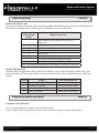
1
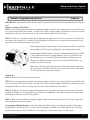
CM6000 Alarm and Starter
Installation Manual
MODEL: RF-2W900FM-5PT
Firstech, LLC.
21911 68th Ave S.
Kent, WA 98032
Phone. 888-820-3690
Fax. 206-957-3330
Please visit www.firstechonline.com for additional installation resources
Alarm and Starter System
CM6000 Install Guide
Table of Contents
Introduction
Kit Contents
Installation Basics
Remote Programming Routine
Placement and Use of Components
Placement and Use of Components
Common Procedures
Wiring Descriptions
Option Programming Tables
Option Menu Descriptions
Special Option Groups 1 & 2
Option Programming
Troubleshooting
Frequently Asked Questions
Technical Support Contacts Copyright 2009 Firstech, LLC.
www.firstechonline.com | www.compustar.com
CM6000
4
4
5
6
7
8
8
12
19
22
29
29
32
32
35
Page 2
Alarm and Starter System
CM6000 Install Guide
Copyright 2009 Firstech, LLC.
www.firstechonline.com | www.compustar.com
Page 3
Alarm and Starter System
CM6000 Install Guide
www.firstechonline.com | www.compustar.com
Introduction
CM6000
Thank you for purchasing this Firstech system for your vehicle. The following installation manual is intended
for experienced and authorized Firstech technicians. We highly recommend that you contact your local Firstech
dealer and seek professional installation. Call 888-820-3690 or visit our websites at www.compustar.com or
www.firstechllc.com to locate your nearest dealer. If you need additional or replacement remotes and / or online
support please visit www.firstechonline.com.
Caution: The Manufacturer’s warranty will be void if this product is installed by anyone other than an authorized Firstech dealer. Firstech provides installation support services to authorized dealers only.
This manual may change frequently. Please check www.firstechonline.com for updates.
Kit Contents
CM6000
All Firstech FT-6000AS CONT controllers include the following:
-
-
-
-
-
-
-
CM6000 main control module
Wiring diagram sheet
Main ignition wiring harness with two external relays
Wiring harnesses
Hood pin
Mountable bright blue LED
Firstech dual stage shock sensor
RF Kits with remote(s), Antenna, and Antenna Cable are not included with the FT-6000AS CONT.
The following sensors are available but not included with every system:
-
Remote pager sensor (FT-RPS-2) (Optional on 2 Way remote LCD systems only)
-
Firstech secure valet switch (FT-VALET GREY)
-
Thermister temperature sensor (FT-TEMP SENSOR) (2 Way remote LCD systems only)
The remote(s) and antenna are modular and are not specific to the control modules. You have the ability to pair
almost any Firstech remote(s) and antenna receiver to the CM6000. This includes all 4 and 6 pin antennas.
Any questions on contents please contact your distributor or us directly at 1.888.820.3690, Monday through
Friday, 8 AM to 5 PM Pacific Time.
Copyright 2009 Firstech, LLC.
Page 4
Alarm and Starter System
CM6000 Install Guide
Installation Basics
www.firstechonline.com | www.compustar.com
CM6000
If you are new to installing Firstech Series Remote Starts and / or Alarms, we highly recommended that you
thoroughly review this manual to installing your first unit.
Key Points to Consider Before Installation:
You must code remotes to this system before anything will function. Program remotes by cycling the ignition
ON / OFF five times within seven seconds and tap button 1 (0.5 second) on the first remote, and then tap button
1 (0.5 second) on the second remote.
RPS-2 (Remote Paging Sensor): The optional RPS that has four main functions; (1.) Status LED, (2.) Remote notification when triggered, and
(3.) Auto unlock/alarm disarm when a user specific 4 digit knock code is entered via tapping sensor through the
windshield. (4.) You can also now relock your vehicle if equipped through the RPS-2 sensor.
Secure Valet:
This optional switch breaks the internal ignition connection to prevent the system from being put into valet
when cycling the ignition ON / OFF five times.
Internal green loop must be cut for AUTOMATIC transmission vehicles.
By default, the units come in MANUAL transmission mode. You will need to cut the green loop inside the control module if you are installing the unit in a AUTOMATIC transmission.
Tach learning procedure:
Learn tach by: (1.) Starting the vehicle with the key, (2.) Press and hold the foot brake, then (3.) Hold the remote start button on the remote for 2.5 seconds - one chirp and parking light flash indicates that the vehicle tach
signal has been successfully learned. Two chirps and two parking light flashes indicate that the control module
failed to see a proper tachometer signal. (These units have the option for Tachless and 1.5 second assume cranking).
New Option Menus:
It is important to familiarize yourself with all the options as it will save time in most applications. For instance,
Option 1-04 controls the double pulse unlock feature on all CM6 series control modules.
Programmable Output Connectors (POC)
Must have Option Programmer OP500
All control modules come with 9 programmable outputs that can be configured 19 different ways. It is important
to familiarize yourself with the POCs as it will save time in most applications.
Internet updatable processors
Visit www.firstechonline.com
All CM6 series units are equipped with some of the most powerful processors available today. This flexibility
allows for on-demand internet updating capabilities in the event of a version update or change.
Copyright 2009 Firstech, LLC.
Page 5
Alarm and Starter System
CM6000 Install Guide
Remote Programming Routine
www.firstechonline.com | www.compustar.com
CM6000
IMPORTANT: Any and all remotes must be coded to the control module prior to performing any and all operations.
Remotes excluding 2WSSR-Pro
STEP 1: Activate programming mode by manually turning the vehicle’s key between the Ign On and Off (or the
Acc & On positions) five times within 7 seconds. The vehicle’s parking lights will flash once with the successful
completion of this step. (Note: this step also places the control module into Valet Mode)
STEP 2: Within a 2 second period after the 5th ignition cycle tap Button I on two way remotes or the Lock button on one-way remotes for 0.5 seconds. The parking lights will flash once to confirm the transmitter has been
coded. Repeat for additional remotes, up to three.
Exiting Programming: Programming is a timed sequence. After 2 seconds the
parking lights will flash twice signaling the end of programming mode.
Programming Multiple Remotes: After the confirmation flash given in STEP
2, code additional remotes by tapping Button I on two way remotes or the
Lock button on one way remotes. The parking lights will flash once confirming each additional remote. All systems (except the PWSSR-Pro), can
recognize up to three remotes.
Note: If you do not program any remotes and enter this sequence it will put
the system into Valet Mode. Only the keyless entry will work in Valet Mode.
To exit Valet Mode just program remote(s).
2WSSR-Pro
STEP 1: Remove the AA battery from the remote.
STEP 2: Activate programming mode by manually turning the vehicle’s key between the Ign On and Off (or the
Acc & On positions) five times within 7 seconds. The vehicle’s parking lights will flash once with the successful
completion of this step. (Note: this step also places the control module into Valet Mode)
STEP 3: Within a 2 second period after the 5th ignition cycle, insert the AA battery into the remote. The parking lights will flash once to confirm this step. If you have an additional 1 Way remote tap the Lock button after
inserting the AA battery into the 2 Way remote.
STEP 4: Wait several seconds for the parking lights to flash twice and the remote LCD to receive a page back.
The transmitter has now been coded.
Programming Multiple Remotes: After the confirmation flash in step 3, program the optional 1 Way remote
by tapping the Lock button for 0.5 seconds. The parking lights will flash once confirming that the 1 Way this
remote has been learned. The 2WSSR-Pro can recognize (1) 2 Way remote and (1) 1 Way remote.
Copyright 2009 Firstech, LLC.
Page 6
Alarm and Starter System
CM6000 Install Guide
Placement and Use of Components
www.firstechonline.com | www.compustar.com
CM6000
IMPORTANT: The placement and use of components are critical to the performance of this system.
Antenna and Cable
Firstech antennas are calibrated for horizontal installation at the top of the windshield. The cable that connects
the antenna to the control module must be free from any pinches or kinks. Installing the antenna in areas other
than the windshield may adversely affect the effective transmitting distance of the remotes.
RPS-2 (Remote Paging Sensor)
The RPS-2 sensor is designed to be mounted on the inside of the windshield. Basic RPS functions do not require programming. There is a three position switch on the rear of the RPS-2. This adjusts the sensitivity of the
RPS-2. The larger the circle the more sensitive the knock is. The RPS-2 can now relock/rearm your vehicle.
Just knock 5 times without the ignition on and door open and it will rearm. To activate the RPS unlock / disarm
feature you must perform the following procedure:
STEP 1: Disarm/unlock the alarm. (Remotes must be programmed first.)
STEP 2: Turn ignition key to the “on” position and the leave the driver’s door open.
STEP 3: Knock on the windshield in front of the RPS a total of 5 times (each time you knock the LED on the RPS will flash RED).
The LED will begin to flash rapidly in BLUE with successful completion of this step.
STEP 4: Enter the first digit of the desired four-digit pass code by knocking on the windshield in front of the RPS the desired number
of times. For example, to enter 3, knock on the sensor 3 times (each time you knock the LED will flash RED) then wait.
STEP 5: The LED on the RPS will confirm your first number by flashing BLUE slowly. Once the LED begins to flash rapidly in
BLUE, enter your second number by repeating step 4.
STEP 6: Repeat steps 4 & 5 to enter all four numbers.
STEP 7: Turn the ignition OFF. The RPS disarm/unlock feature is now programmed. Repeat steps 3 – 5 to enter your disarm/unlock
code.
**The first two digits of the RPS unlock/disarm pass code will be the default pass code for the Secure Valet (you do not need to
program them independently).
Secure Valet Switch
The optional Secure Valet Switch prevents the alarm from being put into valet mode through cycling the ignition on/off five times. The Secure Valet Switch is more secure than traditional toggle / valet switches because it
requires a two digit code. To program this feature you must perform the following procedures:
STEP 1: Turn on Option 3-10-III.
STEP 2: Turn ignition key to the “on” position.
STEP 3: Hold down the valet switch for 1.5 seconds. The LED on the valet switch will begin to flash rapidly with successful completion of this step.
STEP 4: Enter the first digit of the desired two-digit pass code by depressing the switch the number of times that coordinates with the
desired first number. For example, to enter 3, depress the switch 3 times, then wait.
STEP 5: The LED will confirm the first number by flashing BLUE slowly. Once the LED begins to flash rapidly, enter your second
number by repeating step 4.
STEP 6: Turn the ignition off - the Secure Valet Switch is now programmed. Follow steps 3 – 5 to enter your Secure Valet code.
**The first two digits of the RPS unlock/disarm pass code will be the default pass code for the Secure Valet (you do not need to
program them independently).
Copyright 2009 Firstech, LLC.
Page 7
Alarm and Starter System
CM6000 Install Guide
Placement and Use of Components
www.firstechonline.com | www.compustar.com
CM6000
Firstech Shock Sensor
For best results mount the shock sensor by zip tying it to the vehicles main ignition harness. There is a small
dial on the sensor that ranges from Off to 10. The higher the number on the dial the greater sensitivity of impact.
A small adjustment to the dial can make a significant difference in sensitivity for both 1st and 2nd stages. Recommended dial settings for most vehicles is somewhere between 2 & 4.
Siren
The volume output of the siren chirps can be increased 3 dB by cutting black wire loop located near the base of
the siren. To adjust duration time when the alarm has been triggered, change Option 3-07 – the system default is
30 seconds.
Thermister (Temperature Sensor)
Every 2 Way LCD Firstech RF kit includes an optional thermister, which must be plugged into the 2 pin port of
the control module for use. This plug is blue on the CM6000. The use of the thermister allows the 2 Way remote
to display the vehicle’s interior temperature on the remote LCD (liquid crystal display) as well as permitting the
vehicle to start with timed Hot or Cold starting; see options 2-05, 2-07 and 2-08. IMPORTANT: New thermister
plugs are blue 2 pin connectors on the CM6 series but old white plug thermistors will still work.
Hood Pin
The hood pin switch triggers the alarm in the event the hood is opened while the alarm is armed. The hood pin
also doubles as an important safety feature that prevents the remote start from engaging while the hood is open.
Backup Battery
The backup battery input on the control module / brain is for any optional battery backup unit (sold separately).
The red positive lead (+) acts both as an input and charging output for a 12 Volt battery backup. A backup
battery maintains basic alarm functionality when main vehicle power is lost. See the wiring schematic section
for complete details.
Common Procedures
CM6000
Jumper Settings
Caution: Jumper settings affect the polarity and use of certain outputs. If these jumpers are used incorrectly,
damage to the vehicle and /or control module may occur.
Jumper 1 (Door Trigger Polarity)
Determines the polarity of the door trigger input wire (red/white). In the default position the door trigger
registers negative (-) triggers. To change to a positive (+) trigger, move the jumper.
Jumper 2 (Glow Plug or Key Sense Polarity)
Determines the polarity of the glow plug or key sense input wire (brown/white). In the default position it
monitors a positive (+) glow plug input. To change to a negative (-) input move the jumper. To change from the
glow plug to the key sense setting, you must change Option 4-09.
Copyright 2009 Firstech, LLC.
Page 8
Alarm and Starter System
CM6000 Install Guide
www.firstechonline.com | www.compustar.com
Jumper 3 (Parking Light to Trunk Output)
Determines the output type (not polarity) of the green/white wire on connector one (CN1). In the default
position it provides a positive (+) parking light output. To change to a positive (+) trunk output move the
jumper. A negative (-) parking light output is found on connector three (CN3) and a negative (-) trunk output is
found on connector four (CN4).
Setting Auxiliary Outputs on Connector 2
You Must Have the OP500 Option Programmer
To set auxiliary outputs on the control module involves the new Programmable Output Connector wires (POCs).
You must choose two odd pin wires on the black 18 pin connector that you are not using. For example we will
use POC 8 and 9.
STEP 1: Plug in OP500 and use the Right or Left Arrow Button to scroll through the menu to POC 8 and POC 9 on LCD Line 1.
STEP 2: Use the Up or Down Arrow Button to change the lower number on LCD Line 2 to 10 – Auxiliary 1 or 11- Auxiliary 2.
STEP 3: Scroll up the menu to Option 4-01 and 4-02 and set the options. Please see the Option Table for details.
STEP 4: The Pro control modules have a secure auxiliary option 4-05. This requires you to tap button 4 before you tap button 2 for
Aux 1 or button 3 for Aux 2. On 1-Way remotes you must hold the Trunk and Key/Start buttons for 2.5 seconds then tap the Trunk
button for Aux 1 or the Key/Start button for Aux 2.
STEP 5: If you need to change the time settings of the outputs go to AU1 or AU2 on the OP500. LCD Line 2 is the timed output.
STEP 6: Hold the “W” Write button for 3 seconds to set all the options.
Tach Sensing
The default engine sensing mode is tach. In cold weather climates we recommend using an injector wire verses
a coil wire for tachometer sense. There are new features that adjust tach reading methods on option 2-01.
IMPORTANT: The remotes must be coded prior to setting up tach sensing. Firstech recommends using a digital
multimeter to test for tach.
STEP 1: Start the vehicle with the key. Allow time for the engine to idle down.
STEP 2: Test wire and make connection. At idle the tach wire should test between 1 to 4 Volts AC. As the
vehicle RPM’s increase the voltage on the meter will also increase. Always solder tach connections.
STEP 3: Learn tach. While the vehicle is at idle, hold the foot brake and press and hold the remote start button
on the remote control for 2.5 seconds.
Number of
The parking lights will flash once and the siren
Parking
Light
Tach Error
will chirp once to confirm a good tach signal. The
Flashes
parking lights will flash two times and the siren
will chirp two times to indicate the tach did not
1
Option 2-10 is not in default setting 1
learn. Two seconds following the two flashes, the
2
Key is in the off position
number of parking light flashes will indicate the
3
Bad tach signal. Find a different wire.
cause of the error:
Copyright 2009 Firstech, LLC.
Page 9
Alarm and Starter System
CM6000 Install Guide
www.firstechonline.com | www.compustar.com
Alternator Sensing
Alternator sensing is an alternative method the remote start can utilize to determine if the engine is running.
This is different than the no tach sensing mode so a connection must be made. IMPORTANT: The remotes must
be coded prior to setting up alternator sensing.
STEP 1: Change Option 2-10 to setting 2 - Alternator sensing.
STEP 2: Test wire and make connection. The stator wire is found at the vehicle’s alternator. Change your
multimeter to DC voltage before testing for this wire.
A. At rest, with the ignition off, the stator wire should test 0V DC.
B. Turn the ignition to the run position. The stator wire should now test between 4 – 6V DC.
C. Start the vehicle with the key. The stator wire should now test between 12 – 14V DC at idle.
STEP 3: Process complete – no further programming is required.
No Tach Sensing – (Automatic Transmission Vehicles Only)
No tach sensing is an alternative engine sensing mode. No tach sensing does not require a connection to the
vehicle other than the main ignition harness.
STEP 1: Change Option 2-10 to setting 3 – No tach sensing.
STEP 2: Process complete – there is no further programming required other than adjusting crank time when
necessary (see below).
Adjusting Crank Time: To adjust minimum crank times, refer to Option 2-12. To help ensure successful starting,
the system will automatically add additional crank time to the 2nd and 3rd start attempts. In addition, there is a
built in “Smart Resting Mode”. Traditional tach sensing is still highly recommended for colder climates.
Timed Crank Setting – Automatic Transmissions Only
Option 2-10 setting 4 provides a timed 1.5 second crank for the remote start sequence. This option just cranks
the vehicle for 1.5 seconds and assumes remote start has completed. This option can be used for GM and other
vehicles with built in anti-grind systems.
Green/White Loop
This loop wire determines the transmission setting. The default position (uncut loop) is for manual
transmissions. When the loop is cut, the system will be ready for automatic transmissions. In the default
(manual transmission) mode, the system must be set up in Reservation mode prior to the vehicle being able to
remote start. IMPORTANT: All warranties or claims are void if a controller with a cut loop is installed on a
vehicle with a manual transmission.
Reservation Mode for Manual Transmissions
To remote start a manual transmission vehicle, the system must first be set up in reservation mode. Reservation
mode is designed to prevent the vehicle from remote starting while the transmission is in gear.
Copyright 2009 Firstech, LLC.
Page 10
Alarm and Starter System
CM6000 Install Guide
www.firstechonline.com | www.compustar.com
Installation Requirements
1. The vehicle’s door triggers must be connected to the control module. Prior to making final connections, test
the factory door triggers to ensure that they are functioning properly.
2. The vehicle’s emergency/parking brake wire must be connected to the control module. The proper vehicle
wire usually provides a negative (-) trigger while the emergency / parking brake is set.
3. The vehicle’s clutch must be momentarily bypassed while the remote start cranks the engine. This momentary bypass simulates the clutch being depressed. For complete details on how to wire a momentary clutch
bypass consult your CompuTech program or contact our technical support department by calling 888-820-3690.
IMPORTANT: Do not install a remote start in manual transmission vehicles with convertible / removable tops
and in user’s vehicles that leave their windows down. Firstech nor their authorized dealers will assume responsibility for improper use or install.
Activating Reservation Mode
STEP 1: Start the vehicle with the key. Place the transmission in neutral, remove pressure from the pedal
brake, and set the emergency/parking brake.
STEP 2: Remove the key from the vehicle’s ignition. The vehicles engine should remain running even after the
key has been removed. If the vehicle does not remain running, check the emergency / parking brake connection.
STEP 3: Exit the vehicle and close the door. The vehicle’s engine should shut off upon closing the door. If the
vehicle’s engine does not shut off, check the door trigger connection or wait for the factory dome-light to go
out. The Firstech system is in reservation mode and the vehicle is ready to safely remote start.
Additional Notes
Reservation mode will be cancelled if the control module recognizes the vehicles door, hood or trunk opening –
or if the alarm is triggered. Each time the end user wants to remote start their manual transmission vehicle, they
must set the control module in reservation mode. Reservation mode settings can be programmed with Option
1-06.
Version Diagnostics
All the new control modules come with the ability to check which firmware is on the module. This is
accomplished by turning the ignition on. Then with 2 Way remotes you must hold buttons 1 and 4 together for
2.5 seconds. With the 1 Way remotes you must hold the Lock and Key/Start buttons together for 2.5 seconds.
Current version starts with 1 flash.
Blade Cartridge Slot and Connector
The CM6000 and CM6200. The slot gives you the ability to use the Blade-AL and Blade-TB modules from
Firstech and ADS. With these modules you can virtually eliminate all wire connections between your control
module and bypass module. You only need to connect the main ignition harness and your needed wires on
the 20 pin Blade connector. For more information on how to program and wire the Blade please visit www.
idatalink.com for the specific wiring diagram for that vehicle.
Copyright 2009 Firstech, LLC.
Page 11
Alarm and Starter System
CM6000 Install Guide
www.firstechonline.com | www.compustar.com
The new CM6 Series the Blade connector has a locking tab. Non-locking tab blade harnesses will work
but you MUST TAKE CARE TO NOT PLUG THE HARNESS IN UPSIDE DOWN. Make sure the two
notches on the top of the harness face the top (CM and barcode sticker side) of the brain. When looking at the
wire side of the harness the two notches must be at the top of the plug.
Blade system includes:
1. Blade-AL or Blade-TB (NOTE: These modules are blank and must be flashed on your computer.)
2. 20 Pin locking wiring harness
3. 3 Pin harness used in some installs
IMPORTANT: Install diagrams are not included and must be downloaded from www.idatalink.com/compustar.
When flashing the Blade you can use the Y-Cable OP500 end and not CM4 Series end. ADS and Firstech
recommends using the 4 pin RS232 cable to avoid confusion. Cartridge must be removed to flash the control
module firmware.
NOTE: The ADS-RNG C1, ADS-RNG C2, and ADS-RNG GM3 are not included and must be purchased separately. The 20 pin Blade connector comes only with the Blade cartridge and not the CM6 control modules.
WARNING: Manufacturer or seller assumes no responsibility for any injuries and/or damages caused by
improper care of the product such as decomposition, conversion, and transform done by a user voluntarily.
WARNING: There should be no wiring routed around any pedals which can cause a driving hazard.
Wiring Descriptions
CM6000
Connector 1 (CN1), 6-Pin
Pin 1 White – Accessory 12V positive (+) output. This wire must be connected to the vehicle accessory
/ HVAC blower motor wire. The proper wire will test 0V with the key in the off position, (+) 12V
while key is in the on position, 0V while cranking and back to (+) 12V when the key is returned to
the on position. This wire has a 25 amp fuse on it.
Pin 2 Yellow - Starter 12V positive (+) output. This wire is pre-wired to Pin 87a of the anti-grind/starter-kill relay. This wire must be connected for remote start. The proper wire will test 0V with the key in the off
position, 0V while the key is in the on position and (+) 12V during crank. Copyright 2009 Firstech, LLC.
Page 12
Alarm and Starter System
CM6000 Install Guide
www.firstechonline.com | www.compustar.com
There are two wires coming off of the relay; yellow-black and yellow. To utilize the anti-grind or starter-
kill features, the vehicles starter wire must be cut in half, otherwise, cut the relay out of the harness and connect the yellow (Pin 6) directly to the vehicles’ starter wire. The starter kill/anti grind relay has a thin 24 guage blue wire. This must be connected to pin 1 (24 guage blue wire) on Connector 3.
IMPORTANT: For anti-grind and starter-kill applications, the yellow wire goes to the starter side of the vehicles starter wire and the yellow/black goes to the key side.
Pin 3 Green – Ignition 12V positive (+) output and input. This wire must be connected to the vehicles ignition for remote start and valet/program
ming. The proper wire will test 0V with the key in the off position, 12V (+) while the key is in the on posi-
tion and 12V (+) during crank. This pin also has a thin green wire that is
prewired to the starter kill relay. If you are not installing anti grind/starter kill, you do not need to con
nect the thin 24 guage green wire.
Pin 4 Black - Ground negative (-) input. This wire must be connected to the vehicle’s ground.
Pin 5 Red - Constant 12V positive (+) power input. These two wires must be con
nected. The proper vehicle wire will test
(+) 12V at all times while the key is in the off position, the on position and during crank. Each wire has a 30 amp fuse on it. An optional relay with a 14 guage red wire and 30 amp fuse is for secondary ignition/accessory/starter wires. The short violet wire on Pin 85 is the trigger input wire that determines the (+) 12V output type of the long blue wire on Pin 30. For example, connecting the negative (-) Ignition output from Connector 3, to the short violet wire coming off of the relay, will provide an additional (+) 12V Ignition output from the long blue wire.
Copyright 2009 Firstech, LLC.
Page 13
Alarm and Starter System
CM6000 Install Guide
www.firstechonline.com | www.compustar.com
Pin 6 Green/White – This is a dual-purpose wire that features selectable functionality thru the trunk/light jumper on the control module. It is either a positive (+) parking light output or positive (+) trunk output. This wire carries a 10 amp fuse.
Default - Parking light positive (+) output. The proper vehicle wire will test (+) 12V when the parking light switch is in the on position.
Optional – Trunk release positive (+) output. The proper vehicle wire will test (+) 12V when the trunk release is triggered.
Connector 2 (CN2), 2-Pin: Optional Battery Back-up
Pin 1 Red - Constant 12 V positive (+) input and (+) charging output.
Pin 2 Black - Ground (-) negative input.
Connector 3 (CN3), 20-Pin: Programmable Output Connector (POC)
IMPORTANT: Odd Pin numbers 1 through 17 are programmable for up to 12 different output types. Refer to
Special Option Group 2 for complete details.
Pin 1 Blue - 250mA negative (-) output when armed and during remote start (while running). This wire is pre-wired to the anti-grind/starter-kill relay. Caution: When this wire is being used to trigger aftermarket accessories it must be diode isolated.
Pin 2 Orange/Black - Parking Light Reminder (-) input that monitors the vehicle’s parking lights. It prevents the unit from setting Reservation Mode if this wire sees input.
Pin 3 Green/White [POC 1] - Parking light 250mA negative (-) output. The proper wire will test (-) when the parking light switch is in the on position.
Pin 4 Light Blue – Parking / Emergency brake negative (-) input. This input is required for manual transmis
sion/reservation and turbo-timer mode. The proper wire will provide a (-) trigger when parking / emer
gency brake is set.
Pin 5 Red/Black [POC 2] – 2nd Starter 250mA negative (-) output. This output can be used to trigger the pre-
wired relay located on the main ignition harness.
Pin 6 Light Blue/White - Brake 12V positive (+) input. This input must be connected as it provides a shut down for the remote start. The proper wire will test (+) 12V while the foot brake is pressed.
Pin 7 Green [POC 3] - 2nd Ignition 250mA negative (-) output. This output can be used to trigger the pre-
wired relay located on the main ignition harness.
Copyright 2009 Firstech, LLC.
Page 14
Alarm and Starter System
CM6000 Install Guide
www.firstechonline.com | www.compustar.com
Pin 8 Violet/Black - Trunk negative (-) input. This is an optional input that will monitor when the vehicle’s trunk has been opened. The proper wire will provide a (-) trigger while the trunk is open.
Pin 9 White/Black [POC 4] - 2nd Accessory 250mA negative (-) output. This output can be used to trigger the pre-wired relay located on the main ignition harness.
Pin 10
Red/White - Door trigger input. This wire monitors negative (-) or positive (+) trigger door-pins. The proper wire will provide a (-) trigger or a (+) trigger only when the doors are opened. You will need to test the wire for proper polarity and set door dip switch on the control module for the corresponding polarity. IMPORTANT: This wire is required for manual transmission remote starts.
Pin 11 Black [POC 5] – Status/Ground while running 250mA negative (-) output. This is an optional output that will provide a negative (-) output before the ignition cranks and stay on throughout the remote start dura
tion. This wire is most commonly used to trigger bypass / transponder modules.
Pin 12 Brown/White - This is a dual-purpose wire that is selectable through Option 4-9 in the programming able. Select the polarity through the glow/key jumper on the control module. It can be set to ac
cept either a positive (+) or negative (-) wait to start input / key sense.
Default – Glow plug positive (+) or negative (-) input. The proper vehicle wire will show a (+) or (-) trigger while the wait to start light is on. This wire will delay the starter output momentarily to allow the glow plugs to warm up on vehicles equipped with a diesel engine. You can adjust the delay with Option 2-3.
Optional – Key sense positive (+) or negative (-) input. The proper wire will show a (+) or (-) trigger only when the key is in the ignition. The purpose of the key sense is to prevent the system from passively arming or setting reservation mode while the key is still in the ignition.
Pin 13 Orange [POC 6] - Factory Arm 250mA negative (-) output. This is an optional output that will provide a (-) pulse during lock, after crank and again after the ignition shuts down.
Pin 14 Pink - Slave/Closed Loop negative (-) input. This is a dual-purpose optional input that can be changed through Option 4-10.
Default: Slave/Timer Start (-) input. This is most commonly used when adding a remote start to a fac
tory keyless entry system. You can adjust the number of pulses with Option 2-4.
Optional: Closed Loop (-) input. This wire acts as an instant trigger when separated from ground (-). It is most commonly used to protect headlights or trailers.
Pin 15 Orange/White [POC 7] - Factory Disarm 250mA negative (-) output. This is an optional output that will provide a (-) pulse during unlock and prior to the ignition turning on.
Pin 16 Yellow/Black - Engine sensing input. This wire is connected to the vehicles Tach or Alternator wire and is required if you are not using the no tach sense setting. IMPORTANT: To change engine-sen
ing modes, you must change Option 2-10; Default requires a Tach input.
Copyright 2009 Firstech, LLC.
Page 15
Alarm and Starter System
CM6000 Install Guide
www.firstechonline.com | www.compustar.com
Pin 17 White [POC 8] - Horn honk 250mA negative (-) output. This is an optional output that will pulse the factory horn. The proper wire will show ground (-) while the horn is sounding. To change horn output settings, review Options 3-8 and 3-9.
Pin 18 Gray/Black – Hood Pin negative (-) input. This input is a safety shut down and alarm trigger. It prevents the vehicle from remote starting while the hood is open and triggers the alarm if the hood is opened while the alarm is armed. You can connect this wire to the hood pin supplied with this kit, or to a wire in the vehicle that shows (-) only while the hood is open.
Pin 19 Violet [POC 9] - Auxiliary 1 - 250mA negative (-) output. This is an optional output that will provide a pulsed, latched, or timed negative output when triggered by the remote(s). This can be used for power sliding doors, window modules or other outputs.
Pin 20 Brown - Siren 12V positive (+) output. Connect this wire to the (+) wire located on the siren. To change siren output settings, review Option 3-7.
Connector 4 (CN4) , 20 Pin Blade Connector - New Generation
This connector is used only if you are installing a Blade-AL or Blade-TB. The wiring harness for this connector
only comes with the Blade cartridge. Please refer to the Blade install guide for wire description. The new CM6
Series the Blade connector has a locking tab. Non-locking tab blade harnesses will work but you MUST
TAKE CARE TO NOT PLUG THE HARNESS IN UPSIDE DOWN. Make sure the two notches on the
top of the harness face the top (CM and barcode sticker side) of the brain. When looking at the wire side of the
harness the two notches must be at the top of the plug.
Connector 5 (CN5), 6-Pin
Pin 1 Not used
Pin 2 Violet/White - Trunk release 250mA negative (-) output. This is an optional output that will release the trunk. Use CN1, Pin 2 if the vehicle is equipped with a (+) trunk release. System will unlock doors and disarm alarm prior to trunk release.
Pin 3 Orange/Black - 2nd Unlock 250mA negative (-) output. This is an optional output that will provide a (-) pulse for driver’s priority door lock. IMPORTANT: You must isolate the driver’s door and turn on Op
tion 1-3.
Pin 4 Blue - Unlock 250mA negative (-) output. This is an optional output that will provide a (-) pulse for unlocking doors. System will unlock doors and disarm alarm. IMPORTANT: You must reverse polarity for (+) trigger door lock systems. For additional lock settings review Option Group 1.
Pin 5 Blue/Black - Lock 250mA (-) negative output. This is an optional output that will provide a (-) pulse for locking doors. System will lock doors and arm alarm. IMPORTANT: You must reverse polarity for (+) trigger door lock systems. For additional lock settings review Option Group 1.
Copyright 2009 Firstech, LLC.
Page 16
Alarm and Starter System
CM6000 Install Guide
www.firstechonline.com | www.compustar.com
Connector 6 (CN6), 4-Pin (RS 232 Data Port)
This connector is used for updating control modules via www.firstechonline.com. You must also use this port to
flash Blade bypass modules. This port provides simple connectivity of Fortin and iDataLink bypass modules.
Connector 7 (CN7), 3-Pin (Pre-wired Valet/Programming Switch)
Pin 1 Gray/Black - Negative (-) ground.
Pin 2 Gray – 3V positive (+) L.E.D. output.
Pin 3 Gray – Negative (-) output.
Connector 8 (CN8), 2-Pin (Pre-wired Thermister)
Plug optional thermister into this connector to monitor the vehicle’s temperature. It used in conjunction with
Timer Start features along with displaying temperature on two-way LCD’s. To use Timer Start features review
Option Group 2. IMPORTANT: Thermister plugs are blue 2 pin connectors on the CM6 series but old white
plug Thermisters will still work.
Pin 1 Black - Thermister
Pin 2 Black/White - Thermister
Connector 9 (CN9), 4-Pin to 4-Pin or 6-Pin (Pre-wired Antenna Cable)
Connect your antenna cable to this port. You can only use 4 to 4 pin or 4 to 6 pin antenna cables. 6 to 6 Pin antenna cables do not work. Do not use both Connector 9 and Connector 10 at the same time.
Pin 1 Yellow - RX input. This wire receives the signal from remote.
Pin 2 White - TX output. This wire transmits the signal to remote.
Pin 3 Red – Constant 12V positive (+) output.
Copyright 2009 Firstech, LLC.
Page 17
Alarm and Starter System
CM6000 Install Guide
www.firstechonline.com | www.compustar.com
Connector 10 (CN10), 6-Pin to 6-Pin (Pre-wired Antenna Cable)
Connect your antenna cable to this port. You can only use 6 to 6 pin antenna cables. 4 to 4 or 4 to 6 Pin antenna
cables do not work. Do not use both Connector 9 and Connector 10 at the same time.
Pin 1 Yellow - RX input. This wire receives the signal from remote.
Pin 2 White - TX output. This wire transmits the signal to remote.
Pin 3 Red – Constant 12V positive (+) output.
Pin 4 Black – Negative (-) ground.
Connector 11 (CN11), 2-Pin (Pre-wired LED)
Note: Do not mistake for Thermister port.
Pin 1 Black - L.E.D negative (-) ground.
Pin 2 Black/White- L.E.D. 3V positive (+) output.
Connector 12 (CN12), 4-Pin (Pre-wired RPS)
Pin 1 Black - Negative (-) ground.
Pin 2 White - Negative (-) paging input.
Pin 3 Red - 12V positive (+) output.
Pin 4 Yellow - 9V positive (+) L.E.D. output.
Connector 13 (CN13), 4-Pin (Pre-wired Shock Sensor)
Pin 1 Black - Negative (-) ground.
Pin 2 White - 2nd stage negative (-) input. (Instant trigger)
Pin 3 Red - 12V positive (+) output.
Pin 4 Yellow - 1st stage negative (-) input. (Warn away)
Copyright 2009 Firstech, LLC.
Page 18
Alarm and Starter System
www.firstechonline.com | www.compustar.com
CM6000 Install Guide
Connector 14 (CN14), 4-Pin (Optional Sensor Input)
This connector provides optional sensor inputs. Most commonly used with proximity and tilt sensors.
Pin 1 Black – Negative (-) ground.
Pin 2 Black/White - 2nd stage negative (-) input. (Instant trigger)
Pin 3 Red – 12V positive (+) output.
Pin 4
Grey/White - 1st stage negative (-) input. (Warn away)
Option Programming Tables
Feature
CM6000
Option Group 1
Default Setting - I
Optional Setting - II
Optional Setting - III
Optional Setting - IV
Lock After Remote
Start Only
0.125 sec
Lock After Shutdown
Only
3.5 sec
After Start Only
After Shutdown Only
1-02
1-03
1-04
Unlock before, Lock after,
starting
Lock / Unlock pulse duration
Driver's priority unlock
Double pulse unlock
1-05
Rearm Output
1-06
Reservation Lock
(Manual transmissions)
1-07
Unlock / Disarm With Trunk
Release
1-08
Passive Mode
1-09
Ignition controlled door locks
Off
On
1-10
Auto Relock
(If a door is not opened within
this amount of time)
Off
30 sec
60 sec
5 min
1-11
Ignition / Accessory Out Upon
Unlock
Off
Ignition Pulse - same
timing as disarm pulse
Acc Pulse - same timing as disarm pulse
Ignition and Acc
Pulse - same timing as
disarm pulse
Double Pulse Disarm Input
Auto Lock Mode
(2 Way International Remotes)
Single Pulse
Double Pulse
Off
On
Trunk Output Timing
1 sec
0.5 sec
1-01
1-13
1-14
1-15
Copyright 2009 Firstech, LLC.
Off
On
0.8 sec
Off
Off
After Start Shutdown
and First Lock
2.5 sec
On
On
After Start Shutdown
and Every Lock
Locks When Reservation Mode is Set
Does Not Lock When
Reservation is Set
Unlock, Factory Dis- Factory Disarm, Trunk
arm, and Trunk Release
Release Only
Passive locking with
Off
Passive Arming
Reservation Sets 10
Seconds After the Last
Door is Closed
Trunk Release Only
No Passive Locking
with Passive Arming
RPM Locks (Tach
Sensing Mode Only)
2 sec
Page 19
Alarm and Starter System
www.firstechonline.com | www.compustar.com
CM6000 Install Guide
Feature
Option Group 2
Default Setting - I
Optional Setting - II
Optional Setting - III
Low Threshold Tach
Method
1Min
Optional Setting - IV
Double Pulse
Triple Pulse
Cold and Hot Start
2-01
Tach Sensing Method
Optimal Tach Method
Previous Tach Method
2-02
Turbo Timer
Off
2-03
Diesel Timer
Wire
2-04
Trigger Start
Cold or Hot Start with Thermistor Assembly
Off
2 Min
3~99sec
(10sec Default)
Single Pulse
Off
Cold Start Only
Hot Start Only
2-06
Timer Start, or, Minimum
Interval Between Cold Starts
3 Hour (4 minute
runtime, double for
Diesel)
1.5 Hour(4 minute
runtime, double for
Diesel)
Reservation (Runtime
set by 2-7) 2 Way LCD
Remotes Only
2-07
2-08
2-09
Remote Start Runtime
Temperature of Cold Starting
Temperature of Hot Starting
15 Min
-10° C / 14° F
25° C / 77° F
25 Min
-20° C / -4° F
30° C / 86° F
45 Min
-5° C / 23° F
35° C / 95° F
2-10
Engine Sensing
Tach
Alternator
No Connection – No
Tach Sensing
(Tachless Mode Only)
2-11
Turbo, Remote Start Runtime
Extension w/ #1 for 2 seconds
No
Yes
2-12
Crank Time
Standard
+0.2 Seconds to Crank
Time
2-13
Timer Mode
Off
On
2-05
4 Min
24 Hour Repeat with
Cold Starting of 2-8
(Runtime set by 2-7) 2
Way LCD Only
3 Min
-15° C / 5° F
40° C / 104° F
No Connection – 1.5
Second Crank
(Not for Manual Transmissions)
+0.6 Seconds to Crank
Time
(-)0.2 Second Crank
Time
Optional Setting - IV
Option Group 3
Feature
Default Setting - I
Optional Setting - II
Optional Setting - III
3-01
Parking lights While Remote
Started
Constant Output
Flashing Output
Off
3-02
Dome Light output
Off
Factory Rearm
45 sec
3-03
Dome Light Delay
5 sec
3-04
Starter-Kill Relay
Off
Anti-Grind + Starter
Kill
3-05
Anti-Jacking
Starter-kill
(No Anti-Grind)
Ignition-Kill
45 sec
Anti-Grind + Passive
Starter Kill
Auto kill
(Auto-door locks Off)
International Remotes
w/ AUTO Function
Only
3-07
Siren Duration
(Upon Alarm Trigger)
30 sec
60 sec
Copyright 2009 Firstech, LLC.
Anti-Grind
120 sec
Factory Rearm + 45
sec
Auto
Auto kill
Chirps for 20 seconds
Page 20
Alarm and Starter System
www.firstechonline.com | www.compustar.com
CM6000 Install Guide
Option Group 3 Continued
Feature
Default Setting - I
Optional Setting - II
3-09
Horn Output When Alarm Is
Triggered
Pulsed Output
Constant Output
(Secondary Siren)
3-10
Valet
3-11
Auxiliary Settings Mode
Auxiliary Settings With Passive Arming
3-12
3-13 Defroster Temperature Control
Key 5 times, or Remote
Key 5 times or Remote
(I+III) while Ignition
(I+III)
is On
Disabled
Enabled
No Passive Arming
Passive Arming
Standard
Only below 32 degrees
F
Optional Setting - III
20 sec
Optional Setting - IV
Program
Latch
60 sec
Program
By Remote
Arm
Disarm
By Remote
Arm
Disarm
On
Off
Prewarn
Trigger
Trigger
Prewarn
(-)Disarm
(-)Arm
Off
10 sec
30 sec
Glow Plug Input
Key Sense Input
Closed Loop System
Input
Fortin
1 Day Later
On
0.5 sec pulse
3 min latch
3-15
Soft Disarm
Off
On
4-01
Feature
Aux 1 output
Default Setting - I
0.5sec
4-02
Aux 2 output
0.5sec
4-03
Aux 1 output Control
4-04
Aux 2 output Control
Secure Aux Output
(1 and 2 Only)
Auxiliary Input 1 – Green CN
Auxiliary Input 2 – Green CN
Extended Accessory After Ign
Shutoff
Key Sense or Glow Plug input
Trigger Start or Closed Loop
Alarm Trigger Input
Bypass Through RS232 Port
Antenna Power Save
Low Battery Warning
4-08
4-09
4-10
4-11
4-13
4-14
Copyright 2009 Firstech, LLC.
Secure Valet
(Default code 3,3)
Constant Output Until
Remote Start Shuts
Down
Defroster Output Timing
4-06
4-07
Optional Setting - IV
7 min latch
3-14
4-05
Optional Setting - III
Trigger Start input
ADS
Off
Off
Option Group 4
Optional Setting - II
Latch
2 Days Later
Negative (-) out w/ign
shutdown
Panic
(+) Disarm
(+) Arm
Until Door Open
(1 min max)
3 Days Later
Page 21
Alarm and Starter System
www.firstechonline.com | www.compustar.com
CM6000 Install Guide
Special Option Group 1
Feature
Diesel Timer - DISL
AUX1 output time
AUX2 output time
AUX3 output time
AUX4 output time
AUX5 output time
AUX6 output time
AUX7 output time
1
2
3
4
5
6
7
8
Feature
Programmable
Output Connector
Setting Value (Seconds)
3 ~ 99
1 ~ 100
1 ~ 100
1 ~ 100
1 ~ 100
1 ~ 100
1 ~ 100
1 ~ 100
Special Option Group 2
Setting and OP500 Value
0 - Default Setting
1~19 – Optional Settings
1
POC #1
(-) 2nd Parking Light (Green/White)
2
POC #2
(-) 2nd Start (Red/Black)
3
POC #3
(-) 2nd Ignition (Green)
4
POC #4
(-) 2nd Accessory (White/Black)
5
POC #5
(-) Status/GWR (Black)
Aux1 Out - [10] Aux2 Out - [11] Defrost - [12]
6
POC #6
(-) Rearm Wire (Orange)
Aux4 Out - [13] Aux5 Out - [14] Aux6 Out - [15]
7
POC #7
(-) Disarm Wire (Orange/White)
8
POC #8
(-) Horn (White)
9
POC #9
(-) Auxiliary 1 (Violet)
Option Menu Descriptions
2nd Light - [1] 2nd Start - [2]
2nd IG1 - [3]
2nd Acc - [4] Status Out - [5] Rearm Out - [6]
Disarm Out - [7] Horn Out - [8] Dome Light - [9]
Aux7 Out – [16] Defrost - [17] GWA - [18]
Status 2 For Manual Trans. - [19]
CM6000
1-01 Unlock Before, Lock After Starting. Lock After Remote Start.
If enabled, this option will make the system unlock the doors before remote starting, start the vehicle, then lock the doors after the vehicle starts. It will then lock the doors again if the remote start run time
expires and the vehicle shuts down. This feature is for vehicles that have factory alarms that need to be
disarmed before remote starting.
1-02 Door Lock/Unlock Pulse Duration.
This option determines the output duration of the door lock and unlock pulses. Some vehicles do not respond to short door lock/unlock pulses.
1-03 Driver’s Priority Unlock - If enabled, this option will cause the system to unlock the driver’s door first, and if the unlock button is pressed again within 3 seconds, the other doors will unlock. The driver’s door must be isolated from the other doors. Use the Orange/Black CN4 for your 2nd Unlock output.
Copyright 2009 Firstech, LLC.
Page 22
Alarm and Starter System
CM6000 Install Guide
www.firstechonline.com | www.compustar.com
1-04 Double Pulse Unlock - If enabled, this option will cause the system to double pulse the unlock output. This option is used on a majority of Toyota vehicles. The first unlock pulse disarms the alarm, and the second pulse unlocks the doors.
1-05 Rearm Output - These optional settings change the event trigger on the orange rearm wire.
1-06 Reservation Lock - Manual transmission only. Setting III will provide a 10 second delay before the vehicle shuts off after closing the last door to allow for another door to open. Upon a door opening, the user will have 2 minutes to close the last door in order for reservation mode to set.
1-07 Unlock / Disarm with Trunk Release - This option sets that the unlock and/or factory disarm wires do during remote trunk release. The options are pretty self explanatory.
1-08 Passive Mode - This option comes with default off. This feature controls what the lock wire does during passive mode.
1-09 Ignition Controlled Locks - Setting 2 will lock the doors when the foot brake is pressed and doors
closed. Tach sensing mode must be used for setting 3. You must also turn this feature on through the remote by tapping I+IV (2 Way remotes) or Lock+Key (1 Way remotes).
1-10 Auto Relock – This option will automatically relock/rearm after the system has been disarmed and the doors have not been opened.
1-11 Ignition / Accessory Upon Unlock – This option will pulse the ignition wire, accessory, or both upon unlock/disarm. Most new Chrysler vehicles need the ignition and accessory pulsed to disarm the factory alarm.
1-13 Double pulse disarm - This feature changes the behavior of the small orange/white disarm wire. When the feature is turned on it will change the default single pulse to double pulse upon disarm/unlock.
1-14
Auto Mode - This option turns the auto lock/arm and unlock/disarm feature on. This is only available with international 2-Way remotes. The user must also turn this feature on with the remote by holding
button1 for 2.5 seconds. This mode will automatically lock/arm and unlock/disarm when the user leaves or enter the range of the vehicle.
1-15 Trunk Output Timing - This option changes the time of the output pulse on the violet/white wire during trunk release. The default setting is 1 second. With the two options you can shorten to lengthen the out
put by minimum of 0.5 seconds to a maximum of 2 seconds.
Copyright 2009 Firstech, LLC.
Page 23
Alarm and Starter System
CM6000 Install Guide
www.firstechonline.com | www.compustar.com
2-01 Tach Sensing Method – This option will adjust the method at which tach is read by the module. At de
fault this option will minimize overcrank during remote start.
2-02 Turbo Mode – This option will adjust the run time after Turbo mode has been engaged. The e-brake and door trigger inputs must be connected and the option must be turned on through the remote for turbo timer to engage.
2-03 Diesel Timer – Use this option if you can’t find the glow plug wire. You can use setting 2 for a default wait to start of 10 seconds, otherwise, you can adjust the time with your OP500 Programmer.
2-04 Trigger Start – This option changes the number of times required for a negative (-) start input on the pink wire of connector 2.
2-05 Cold or Hot Start – This option turns on the cold/hot starting features. This option works in conjunction with 2-6, 2-8 and 2-9. The thermister must also be connected the brain.
2-06 Timer Start or Interval Between Cold Start - This option dictates the time interval when the control mod
ule will either remote start or check the temperature and remote start.
Default 1: Will start every 3 hours until the vehicle is remote started or started by key and run for 4 min
utes.
Option 2: Will start every 1.5 hours until the vehicle is remote started or started by key and run for 4 minutes.
Option 3: Will start at the time specified on the 2 way remote once within 24 hours and run based on Option 2-07.
Option 4: Will start once every 24 hours if the temperature falls below Option settings 2-08 or above Option settings 2-09.
For example, if you want your car to start and run 25 minutes when the temperature falls below 32°F, you need to set up the following options:
1) Option 2-05 (Cold Start) turned on,
2) Option 2-06-IV (24 hr. repeat) turned on,
3) Option 2-07-II (25 min run-time) turned on,
4) Option 2-08-IV (Temp 32°F) turned on,
*Set the reservation time at 7 am (see User’s guide)
**Turn on Timer Mode of the 2 way LCD remotes (see User’s Guide)
2-07 Remote Start Runtime - This option give you four different settings for the remote start run time. This available options are 15, 25,45, and 3 minutes.
2-08 Temperature of Cold Starting – Works in conjunction with Options 2-05 and 2-06. See the option table for available temperatures.
Copyright 2009 Firstech, LLC.
Page 24
Alarm and Starter System
CM6000 Install Guide
www.firstechonline.com | www.compustar.com
2-09 Temperature of Hot Starting – Works in conjunction with Options 2-05 and 2-06. See the option table for available temperatures.
2-10 Engine Sensing – Review the “Common Procedures” section for complete explanations on the four engine sensing modes.
2-11 Runtime Extension – This option resets the engine run countdown before the vehicle shuts off for either the remote start or turbo timer. To reset the runtime you must hold the remote start button for 2.5 sec
onds while the unit is still running. This feature is only available on select 2 Way LCD remotes.
2-12 Min. Crank Time - This option controls the minimum crank time for the remote starter. This is only used if in extreme cold climates.
2-13 Timer Mode - This option enables the user to operate Timer Mode (see option 2-06). Remember that the user must still activate Timer mode using the remote (see the user manual for that remote for instructions). This option turns the remote start timer mode on the system.
3-01 Parking Lights while Remote Started - This option changes the parking light behavior during remote start.
3-02
Dome Light Output – This option sets the timing output of the Dome Light wire on CN3.
Default 1: Off
Option 2: Factory Rearm – This system will pulse the dome light output during lock/arm.
Option 3: 45 second Dome Light Output – activates the dome light for 45 seconds upon unlock/disarm.
Option 4: This is a combination of 2 and 3.
3-03 Dome Light Delay – This option is used when connecting the door trigger input to the vehicles dome light circuit. It delays the door trigger input to prevent the door open icon displaying on 2 Way remotes upon lock/arm.
3-04
Starter-Kill – This option determines the mode of the anti-grind/starter-kill relay.
Default 1: Anti-grind + starter-kill
Option 2: Anti-grind only (no starter-kill)
Option 3: Anti-grind + passive starter-kill: starter-kill activates in 45 seconds after ignition is turned off.
3-05
Anti-Jacking – This option requires the starter-kill relay to be wired to the ignition vs. the starter wire.
Default 1: Acts like starter-kill: removes power from the ignition, which allows the car to crank but not start.
Option 2: Turns on anti-jacking: when the remote panics the system, power from the ignition will be removed at the end of the 30 second siren duration, thereby disabling the vehicle.
Option 3 & 4: Only available with Canadian remotes.
IMPORTANT: When using ignition-kill on manual transmission vehicles Option 2 will need to be utilized. Option 2 disables the anti-grind circuit while the vehicle is remote-started; if the anti-grind circuit is active and the start-kill relay is installed in the ignition, the relay will “buzz” while remote-
started.
Copyright 2009 Firstech, LLC.
Page 25
Alarm and Starter System
CM6000 Install Guide
www.firstechonline.com | www.compustar.com
3-07 Siren Duration (Upon Alarm Trigger) - This option changes the time that the siren sounds during alarm trigger. The available options are 30, 60, and 120 seconds. It will also sound chirps for 20 seconds as a fourth option.
3-09 Horn Output When Alarm is Triggered - This changes the behavior of the white horn wire when the alarm is triggered. With this setting you can change the wire to a constant (-) negative output for an ad
ditional siren.
3-10 Valet – This option changes valet modes.
Default 1: Key on/off five times or remote valet (I + III for 0.5 seconds) with key in the on position.
Option 2: Key on/off five times or remote valet (I+III for 0.5 seconds) – key does not need to be in the on position.
Option 3: Secure valet: RPS Valet or remote valet (I+III for 0.5 seconds) – this option prevents the sys
tem from being put into valet via key on/off five times. To set up the RPS Valet feature, review the “Placement and Use of Components” section.
3-11
Auxiliary settings – This option requires the installation of the optional Auxiliary settings module. The Auxiliary settings adds five additional independent auxiliary outputs for a total of seven. With this op
tion turned on, auxiliary 2 becomes non functional and Aux 1 becomes the data wire for the Auxiliary settings. Special Option Group 1 allows for independent timing of these outputs.
3-12 Passive Arming w/Auxiliary settings – The ability to activate/deactivate Passive Arming through the remote is lost once Option 3-11 is turned on. This option allows the use of Passive Arming when using the optional Auxiliary settings.
3-13 Defroster Temperature Control - When set to setting II, this option will disable the defroster output when the temperature is above 32 F / 0 C. Setting I will activate the defroster regardless of the temperature.
3-14 Defroster Timing - Some vehicles need a pulse to activate the defroster, others will need a constant out
put to remain active, you can use this option to adjust the duration of the defroster output.
3-15 Soft Disarm - When a vehicle has a factory alarm, and the Firstech alarm is triggered, you may have both alarms triggered at the same time. In the default setting, silencing the Firstech system will not send the disarm pulse to the factory system, therefore requiring the user to first silence the Firstech system and then unlock and disarm to silence the factory system. Setting II sends the disarm pulse when the Firstech system is silenced.
Copyright 2009 Firstech, LLC.
Page 26
Alarm and Starter System
CM6000 Install Guide
www.firstechonline.com | www.compustar.com
4-01 Aux 1 Output - This option determines the duration of the auxiliary 1 output. Setting IV allows the out
put duration to be set for a specific length of time.
4-02 Aux 2 Output - This option determines the duration of the auxiliary 2 output. Setting IV allows the out
put duration to be set for a specific length of time.
4-03 Aux 1 Output Control - This option controls the way auxiliary 1 is controlled at different events.
4-04 Aux 2 Output Control - This option controls the way auxiliary 2 is controlled at different events.
4-05 Secure Aux Output – On the default setting, button 4 on the remote must be pressed first before Aux 1 or Aux 2 can be triggered. This prevents accidental triggering of the outputs. Option setting II turns this feature off.
4-06 Aux 1 Input – This option changes the input behavior of the pre-warn wire on the Aux Input Sensor green connector.
Default 1: Will pre-warn with a negative (-) ground input.
Option 2: Will instant trigger with a negative (-) ground input.
Option 3: Will disarm the alarm with a negative (-) ground input. Used when adding an alarm to a
factory keyless entry system.
Option 4: Will disarm the alarm with a positive (+) 12V input. Used when adding an alarm to a factory keyless entry system.
4-07 Aux 2 Input – This option changes the input behavior of the instant trigger wire on the Aux Input Sensor green connector.
Default 1:. Will instant trigger with a negative (-) ground input.
Option 2: Will pre-warn with a negative (-) ground input.
Option 3: Will arm the alarm with a negative (-) ground input. Used when adding an alarm to a factory keyless entry system.
Option 4: Will arm the alarm with a positive (+) 12V input. Used when adding an alarm to a factory keyless entry system.
Copyright 2009 Firstech, LLC.
Page 27
Alarm and Starter System
CM6000 Install Guide
www.firstechonline.com | www.compustar.com
4-08 Extended Accessory After Ignition Shutoff – This option keeps the Accessory wire powered up after the ignition is shut off. This can be used to keep the radio turned on even after the key is removed from the ignition (similar to GM vehicles).
4-09
Glow Plug or Key Sense – Default setting sets the wire as a glow plug input. Option setting 2 changes the wire to a key sense input. Key sense can be used to prevent reservation mode from setting and the system from passive arming while the key is still in the ignition. Key sense also turns off dome-light supervision when the key is inserted into the ignition.
4-10
Trigger Start or Closed Loop System – Default setting sets the pink wire on CN3 as a trigger start input, which will initiate remote start with a negative (-) trigger. Option 2-04 allows the number of pulses required to initiate remote start to be changed. Setting 2 changes the wire to a closed loop input, which makes it an instant alarm trigger when separated from ground - Ideal for protecting trailers or headlights.
4-11 Bypass Brand Through RS232 Port – Default setting allows for compatibility with ADS Idatalink
modules. Setting 2 changes compatibility to Fortin bypass modules.
4-13 Antenna Power Save - Some people may not drive their vehicle very often, this may cause the battery to become discharged because it is not getting recharged on a regular basis. The antenna power save option will turn off the antenna after the specified amount of time to conserve power. While the antenna is asleep, the system will not respond to the remotes. Any type of input to the system will wake up the antenna, i.e.: ignition, brake, door, trunk, hood, shock, rps, ect. This means that a remote start only user just needs to open their door to reactivate the system, however, a user with an alarm or alarm/start system will need to trigger the prewar stage of the shock sensor to quietly wake up the antenna.
4-14
Low Battery Warning - This feature option which is default to off. When the system is armed and the feature is on the main control unit will monitor the voltage of the vehicles battery at its connection point. When the battery voltage drops to or below 11 volts the control module will send a page to the 2way. It will beep several times for 5 seconds, every 50 seconds, 3 times and flash the battery indicator on the remote. When you query the remote or unlock/disarm the system the remote will display the voltage of the vehicle’s battery.
Copyright 2009 Firstech, LLC.
Page 28
Alarm and Starter System
CM6000 Install Guide
www.firstechonline.com | www.compustar.com
Special Option Groups 1 & 2
CM6000
IMPORTANT: The OP500 is required to change settings in Special Option Groups 1 and 2.
Special Option Group 1
1
Diesel Timer – Option 2-03 must first be set to setting 2. This special option allows a specific wait to start time (in seconds) to be programmed. This prevents the need for a timer relay and eliminates a con
nection to the “wait to start” wire.
2
Aux 1 Output Timing – Option 4-01 must first be set to setting 4. This special option allows a specific output duration for Aux 1 to be programmed.
3
Aux 2 Output Timing – Option 4-02 must first be set to setting 4. This special option allows a specific output duration for Aux 2 to be programmed.
4-8
Aux 3 – 7 Output Timing – Option 3-11 must first be set to setting 2 and the optional Auxiliary settings module must be used. These special options allow specific output durations to be set for Aux 3 – 7. Only available with 2 Way LCD remotes.
Special Option Group 2
This special option group allows you to determine the output type of the POC wire. For example, if you want to
set POC #5 (default setting status out) to Aux 1, you will need change special option 5 to number 10. This must
be done with the OP500.
Option Programming
CM6000
Option Programming Using the OP500 (programmer)
The OP500 can be used to program any available option. It is required to program options in Special Option
Groups 1 and 2.
STEP 1: Using the blue connector on the top of the OP500, connect it to the control module via the antenna
wire. (Use the included extension cable if necessary.) Once connected, the OP500 will power up as long as the
main ignition harness to the controller has been connected properly.
STEP 2: To change the option number you wish to program, use the left and right arrow keys on the OP500. It
will scroll through the options available in menu 1 and then move to menu 2, then 3 and 4. Use the up and down
arrow buttons on the OP500 to adjust the option settings; “1” is the default setting, and “2”, “3”, and “4” are the
optional settings.
Copyright 2009 Firstech, LLC.
Page 29
Alarm and Starter System
www.firstechonline.com | www.compustar.com
CM6000 Install Guide
At the end of menu 4, if diesel mode or auxiliary setting functions were enabled – or if any of the auxiliary outputs were set to “Program”, the duration of these settings can now be adjusted.
Following the auxiliary and diesel settings (if selected), the POC options will be displayed on the OP500. The
POCs can be set between 0 (default) and 19.
STEP 3: When finished with the adjustment of the various option settings, press and hold the “W” (write) button until the OP500 chirps, which is approximately 2.5 seconds. This will write the settings to the control module. Wait until the module displays “Success” before disconnecting it from the antenna cable.
To reset the options, hold the “R” (reset) button and the “W” (write) button for 2.5 seconds. Release then write
the reset, hold the “W” button until the OP500 chirps, which is approximately 2.5 seconds.
Option Programming Using a Remote
Using a remote is a timed process so read this section in its entirety before beginning. IMPORTANT: Special
Option Groups cannot be programmed with a remote – the OP500 must be used.
STEP 1: Select the option menu that contains the desired programming option.
To program options use the following button combinations:
Copyright 2009 Firstech, LLC.
Select Option 2
Select Option 3
Select Option 4
Tap Button
4
Tap Button
4
Tap Button
4
Tap Button
4
Select Option 1
(1 + 2) for 2.5 seconds then
(1 + 2) for 2.5 seconds
(1 + 2) for 2.5 seconds then
(1 + 4) for 2.5 seconds
(1 + 4) for 2.5 seconds then
(1 + 2) for 2.5 seconds
(1 + 4) for 2.5 seconds then
(1 + 4) for 2.5 seconds
Wait for corresponding parking light flash
and/or siren chirp before selecting the
option
Scroll Through
Menu
(Wait for chirp
between each tap)
Option
Menu 1
Option
Menu 2
Option
Menu 3
Option
Menu 4
With 2 Way
Remotes
(Wait for chirp
between each tap)
How to Program Options with 2-Way Remotes
Tap Button
1
Tap Button
1
Tap Button
1
Tap Button
1
Tap Button
2
Tap Button
2
Tap Button
2
Tap Button
2
Tap Button
3
Tap Button
3
Tap Button
3
Tap Button
3
Tap Button
4
Tap Button
4
Tap Button
4
Tap Button
4
Page 30
Alarm and Starter System
www.firstechonline.com | www.compustar.com
CM6000 Install Guide
Hold Trunk +
Key/Start for
2.5 seconds
Hold Trunk +
Key/Start for
2.5 seconds
Hold Trunk +
Key/Start for
2.5 seconds
Hold Trunk +
Key/Start for
2.5 seconds
Tap Lock
Button
Tap Lock
Button
Tap Lock
Button
Tap Lock
Button
Select Option 4
Select Option 3
Select Option 2
Select Option 1
Wait for corresponding parking light flash and/or
siren chirp before selecting the option
Lock + Unlock for 2.5
seconds then Lock +
Unlock for 2.5 seconds
Lock + Unlock for 2.5
Option
seconds then Lock + Key/
Menu 2
Start for 2.5 seconds
Lock + Key/Start for
Option
2.5 seconds then Lock +
Menu 3
Unlock for 2.5 seconds
Lock + Key/Start for 2.5
Option
seconds then Lock + Key/
Menu 4
Start for 2.5 seconds
Option
Menu 1
Scroll Through
Menu
(Wait for chirp
between each tap)
With 2 Way
Remotes
(Wait for chirp
between each tap)
How To Program Options With 1 Way Remotes
Hold Trunk +
Tap Unlock Tap Key/
Key/Start for
Button
Start Button
2.5 seconds
Hold Trunk +
Tap Unlock Tap Key/
Key/Start for
Button
Start Button
2.5 seconds
Hold Trunk +
Tap Unlock Tap Key/
Key/Start for
Button
Start Button
2.5 seconds
Hold Trunk +
Tap Unlock Tap Key/
Key/Start for
Button
Start Button
2.5 seconds
STEP 2: Scroll through menu allowing for 1 parking light flash and/or siren chirp per step.
STEP 3: Once finished scrolling through the menu wait for the parking lights and/or siren chirp to confirm the
option number. i.e. option 2-04 will flash 4 times. Then use one of the table selections to select the option corresponding to your desired setting.
Resetting to Factory Defaults: To reset the options in a particular menu group, enter the menu shown in the
above tables. To reset options with a 2 Way remote tap button 3 three times. To reset options with a 1 Way
remote tap the Key/Start button 3 times. Wait for the siren to chip and parking lights to flash between each tap.
After the third tap, the option menu will reset and the siren will chirp three times. This must be done for each
option group that needs to be reset.
Copyright 2009 Firstech, LLC.
Page 31
Alarm and Starter System
www.firstechonline.com | www.compustar.com
CM6000 Install Guide
Troubleshooting
CM6000
Remote Start Error Codes
If the remote start fails to start the vehicle, the parking lights will flash three times immediately. Following those
three flashes the parking lights will flash again corresponding to the error table below:
Number of
Parking Light
Flashes
Remote Start Error
Motor running or must program tach before 1st
remote start
2
Key in ignition on position
3
Door open (manual transmission only)
4
Trunk open
5
Foot brake on
6
Hood open
7
Reservation off (manual transmission only)
8
Tach or no tach sensing failure
*Pro 2 Way remotes will display the error number “Strt Er##” on the LCD.
1
Alarm LED Diagnostics
When the alarm is triggered the LED on the RPS (if installed), Secure Valet (if installed) and the LED (if installed) will flash a certain amount of times as shown in the table below. This is intended for users with 1 Way
remotes.
Priority
1
2
3
4
Trigger
Door/Hood/Trunk/Ign Triggered
2nd Shock Triggered
2nd Auxiliary Input Triggered
Panic with remote
Frequently Asked Questions
LED Flash Diagnostic
2 flashes, break, then repeat
3 flashes, break, then repeat
4 flashes, break, then repeat
5 flashes, break, then repeat
CM6000
Frequently Asked Questions
I have everything hooked up and the system will not respond.
A: The remotes need to be programmed. Review the “Common Procedure” section of this manual.
Copyright 2009 Firstech, LLC.
Page 32
Alarm and Starter System
CM6000 Install Guide
www.firstechonline.com | www.compustar.com
I am trying to program the control module with the OP500 Option Programmer and it flashes “ER 01” when I
plug it in to the antenna cable. What should I do?
A: Make sure that the system is not locked/armed. The last thing to check is the antenna cable or antenna extension cable – make sure this is not damaged. If you need to, try another cable. When the OP500 is working
properly, it will read “success good.” You no longer need to program the remotes before the OP500 will sync.
What is the green loop wire inside the brain module?
A: This wire determines the transmission mode. With the loop intact, the system is set for manual transmissions.
With the loop cut, the system is set for automatic transmission.
Where do the blue and purple wires off the extra relay go on the CM6000/CM6200?
A: This is a pre-wired positive output, negative trigger relay. Use the secondary ignition, starter, and accessory
outputs from CN3 to give a negative trigger to the purple wire. This will determine the12V positive (+) output
of the blue wire, which you can then connect to your secondary ignition, starter, or accessory wire.
I need a ground when armed wire, does the control module have one?
A: You can use the starter output on CN1 that goes to the starter kill relay. You must cut this wire and place a
diode in line so that when the ignition on the other side of the relay goes to ground, it won’t back feed to your
accessory. Install the stripe side of the diode facing the control module.
Does the CM6 series have tachless mode?
A: Yes. The CM6000 and CM6200 all are tachless. Review the “Common Procedures” section of this manual.
On the brain, how do I set the auxiliaries?
A: You must have an Option Programmer (OP500) to set the auxiliaries on the CM4000, CM4200-DX,
CM4300, CM5000, CM5200, CM6000, and CM6200. First choose two POC wires on CN3 that you are not
using. With the OP500 go into the Special Option Group 2 and set those POC’s to Aux 1 and Aux 2. Review the
“Special Option Group” programming section of this manual.
All my connections are made and remotes programmed, how do I program the tach?
A: Review the “Common Procedures” section of this manual.
The vehicle remote starts when disarmed, but not when armed.
A: The starter kill relay was installed backwards. Check to make sure the yellow/black wire is going to the ignition side of the wire, and that the yellow wire is going to the engine side.
The vehicle starts and shuts down 3 times in a row.
A: This usually means that the engine sensing mode is not working correctly. If you are using a coil, change to
an injector or try alternator mode.
Copyright 2009 Firstech, LLC.
Page 33
Alarm and Starter System
CM6000 Install Guide
www.firstechonline.com | www.compustar.com
The vehicle will lock and unlock, but will not remote start or flash the parking lights.
A: The system is in valet mode. Tap buttons (I) + (III) for 0.5 seconds while the key is in the on position.
Whenever I try to arm the vehicle, it chirps the siren 3 times and will not arm.
A: Check the hood and trunk trigger inputs.
When I turn the ignition on the parking lights flash 3 times and/or siren chirps 3 times. What is the problem?
A: When you program only 1 Way remotes to a 2 Way antenna and no 2 Way remotes the control module reminds you of this situation each time you turn the ignition on. It does not affect the operation of the system but
will continue to do so until you program both 2 and 1 Way remotes to the 2 Way antenna.
Do the door locks flip flop in polarity?
A: No. You can use the CompuPack (DM700 relay pack) for high current positive (+) locks, or the DM600 harness used for low current 600mA positive (+) locks.
What are Firmware Version Diagnostics?
A: When you turn the Ignition on and hold buttons 1 and 4 or Lock and Key/Start for 2.5 seconds then the parking lights will flash 1 time on the CM6 series showing V.1.
What is this cartridge slot on the rear of the CM6000 and CM6200?
A: This is the slot for the Blade cartridge system. This slot is for the Idatalink Blade remote start bypass
modules. For more information on the compatibility and install information please visit www.idatalink.com/
fitguide. Using this system eliminates many connections between your standard control module and bypass
module. IMPORTANT: If you are not using the Blade then you will not have or use the 20 pin connector next
to the lock harness.
How do I take the system out of Valet Mode with a 1 Button Remote?
A: Turn the ignition on, tap the button 5 times within 7 seconds and the system will exit Valet Mode.
Why are the ignition controlled doorlocks option not working?
A. Check option programming. Option 1-09 should be on either setting 2 or 3. The option has to also be turn on
via the remote. On 2 Way LCD remotes tap buttons I and IV for 0.5 second, the parking lights will flash once to
show the option is turned on. On 1 Way remotes tap the Lock and Start buttons for 0.5 second.
Copyright 2009 Firstech, LLC.
Page 34
Alarm and Starter System
CM6000 Install Guide
Technical Support Contacts www.firstechonline.com | www.compustar.com
CM6000
Firstech technical support is reserved for authorized dealers only.
Monday - Friday:
888-820-3690
(8:00 am – 5:00 pm Pacific Coast Time)
Email:
[email protected]
Web:
Register at: www.firstechonline.com click on “Authorized Tech”
Wire Diagrams
Click on the “Installogy Access Client” link found on your desktop. If you are a qualified dealer and unable to
access this site, call your sales representative or the number above.
Copyright 2009 Firstech, LLC.
Page 35