1
TM
Addressing Printer SA5300
Operator Guide
US/International English Version
FCC Compliance
This equipment had been tested and found to comply with the limits for a Class A digital
device, pursuant to Part 15 of the FCC rules. These limits are designed to provide reasonable
protection against interference when the equipment is operated in a commercial environment. This equipment generates,uses,and can radiate radio frequency energy, and if
not installed and used in accordance with the users manuals,may cause harmful interference
to radio communications. Operation of this equipment in a residential area is likely to cause
harmful interference in which case the user will be required to correct the interference at his
own expense.
CAUTION: Changes or modifications to this equipment not expressly approved by the party
responsible for compliance could void the user ’s authority to operate the equipment.
Shielded cables must be used with this unit to insure compliance with Class A limits.
Canadian DOC Compliance
This digital apparatus does not exceed in the Class A limits for radio noise emissions from
digital apparatus set out in the Interference-causing Equipment Regulations (Standard ICES003)of the Canadian Department of Communications.
Le present appareil numerique n ’emet pas de bruits radioelectriques depassant les limites
applicables aux appareils numeriques de la class A prescrites dans le Reglement sur le
brouillage radioelectrique edicte par le ministere des Communications du Canada.
NOTE: This equipment has been tested and found to comply with the U.S. Standard
for Safety UL1950, Third Edition, Safety of Information Technology Equipment including
Electrical Business Equipment and Canadian Standards C22.2 No 950-95, Third Edition,
Safety of Information Technology Equipment including Electrical Business Equipment.
First Edition, August 2006
SV61867 Rev. A ©2006 SECAP™ USA Inc.
All rights reserved. This book may not be reproduced in whole or in part in any fashion or stored in a
retrieval system of any type or transmitted by any means, electronically or mechanically, without the
express, written permission of SECAP™.
We have made every reasonable effort to ensure the accuracy and usefulness of this manual; however,
we cannot assume responsibility for errors or omissions or liability for the misuse or misapplication of
our products.
Due to our continuing program of product improvement, equipment and material specifications as well
as performance features are subject to change without notice. Your printer may not have some of the
features described in this book. Some features are optional and furnished at extra cost.
Windows is a trademark of Microsoft Corporation.
Contents
Chapter 1
Overview
Using This Guide........................................................................ 1-2
Welcome to the SA5300 Printer................................................ 1-2
System Requirements................................................................ 1-3
Getting Help . ............................................................................. 1-4
Ordering Supplies ...................................................................... 1-4
The World Wide Web.............................................................1-4
Phone Support.......................................................................1-4
Before You Contact SECAP™ USA.......................................1-4
Important Safety Notes............................................................... 1-5
Printer Parts and Locations........................................................ 1-7
Feeder Parts and Locations........................................................ 1-9
Chapter 2
Setting Up Your SA5300 Printer
Choosing a Location................................................................... 2-2
Assembling the Printer................................................................ 2-3
1. Install the Feeder.............................................................2-4
2. Install the Shock...............................................................2-5
3. Install the Side Guides.....................................................2-6
4. Install the Feed Ramp......................................................2-6
5. Connecting the Parallel Cable or USB Cable..................2-8
6. Connect the Power Cord and Turn ON............................2-9
7. Install the Bulk Ink Assembly (Optional)...........................2-10
8. Install the Print Cartridge(s).............................................2-10
Chapter 3
Printer Basics
Setting Up A Job......................................................................... 3-2
1. Set the Separator Gap.....................................................3-2
2. Center the Feed Ramp under the Material......................3-4
Contents
3. Set the Feed Angle..........................................................3-5
4. Set the Feed Ramp Length..............................................3-5
5. Position the Side Guides..................................................3-6
6. Load Material...................................................................3-7
7. Adjust the Media Thickness Knob....................................3-8
8. Output Stacker.................................................................3-9
9. Print a Test Piece.............................................................3-9
10.Set the Print Head Position..............................................3-10
11. Adjust the Takeaway Roller Tension.................................3-11
Chapter 4
Using the SA5300 with Your Computer
Installing the Printer Driver ........................................................ 4-2
Selecting the SA5300 Printer From a Windows Application....... 4-3
Making the SA5300 the Default Print Driver............................... 4-3
Accessing the Print Driver.......................................................... 4-4
The General Tab......................................................................... 4-4
Printing Preferences................................................................... 4-4
The Paper Tab.......................................................................4-4
The Features Tab...................................................................4-5
The Advanced Tab.................................................................4-7
Chapter 5
Printer Maintenance
ii
Replacing the Print Cartridges.................................................... 5-2
Removing Old Print Cartridges..............................................5-2
Installing New Print Cartridges...............................................5-3
Removing the Old Bulk Ink Cartridges...................................5-4
Installing New Bulk Ink Cartridges.........................................5-5
Prolonging the Life of Print Cartridges........................................ 5-6
Print Quality Problems................................................................ 5-7
Cleaning...................................................................................... 5-7
Preventive Maintenance............................................................. 5-7
Contents
Cleaning the Sensor................................................................... 5-8
Cleaning the Exit Idler and Entry Rollers.................................... 5-9
Cleaning the Wipers................................................................... 5-10
Cleaning the Transport Belts and Floor Assembly...................... 5-10
Chapter 6
Troubleshooting Your Printer
Problems and Solutions.............................................................. 6-2
Feed Problems........................................................................... 6-2
Print Quality Problems................................................................ 6-3
Interface Problems...................................................................... 6-6
Motor Problems.......................................................................... 6-6
Other Problems........................................................................... 6-6
Appendix A
Using the Control Panel Menus
Using the Control Panel.............................................................. A-2
Using the Menus......................................................................... A-3
Using the Main Menu.................................................................. A-5
1. Address Layout ...............................................................A-7
2. Print Quality.....................................................................A-9
3. Font Selection..................................................................A-10
4. Barcode............................................................................A-11
5. Address Recovery . .........................................................A-12
6. Clear Counter...................................................................A-13
7. Job Settings.....................................................................A-13
8. Conveyor Time.................................................................A-14
9. Image Overlay..................................................................A-14
10.Purge Print Head.............................................................A-15
11.Reset Ink Counter............................................................A-15
Using the Setup Menu................................................................ A-16
iii
Contents
1. Stop On Feed Err (Error).................................................A-18
2. Feeder Signal...................................................................A-18
3. Lines Per Address............................................................A-19
4. Line Termination...............................................................A-19
5. Hex Dump Mode..............................................................A-20
6. Language.........................................................................A-22
7. Transport Speed..............................................................A-23
8. Postal Bundle Brk (Break)................................................A-23
9. Pre-Purge.........................................................................A-25
10.Feed Gap.........................................................................A-26
11.ROM Revision..................................................................A-26
12.Print Head Size................................................................A-27
Using the Service Menu.............................................................. A-28
1. Adjust Print.......................................................................A-28
2. Test System.....................................................................A-33
3. Test Display......................................................................A-33
Appendix B
SA5300 Specifications
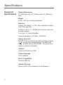
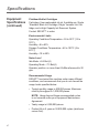
Equipment Specifications........................................................... B-2
Material Specifications (continued)............................................. B-6
Appendix C
Glossary
Glossary...................................................................................... C-1
Index
Index........................................................................................... I-1
iv
Chapter
1
Overview
This chapter explains what's in
this guide, and tells you how to
order supplies and where to get
more information about using your
SA5300.
In this chapter:
Welcome to the SA5300 Printer.....1-2
Using This Guide............................1-2
System Requirements....................1-3
Getting Help...................................1-4
Ordering Supplies...........................1-4
Important Safety Notes...................1-5
Printer Parts and Locations............1-7
Feeder Parts and Locations...........1-9
Overview
Welcome to
the SA5300
Printer
The SECAP™ SA5300 ink jet printer is used to print addresses, graphics and other information, on a wide range
of material of various sizes, construction and composition.
With the SA5300 you can define the font, placement, print
quality and barcode characteristics for your addresses.
This Operator Guide shows you how to:
• Set up the SA5300 printer
• Connect it to your computer
• Define your envelope layout
• Print a test mail piece
• Send a mail job to the printer from your computer
application.
Using This
Guide
Refer to this guide for information about printer setup, operation and troubleshooting. It is organized as follows:
Chapter 1, Overview
Contains an overview of the SA5300 Operator Guide, information about obtaining supplies and help, Safety information and component identification.
Chapter 2, Setting Up
Contains instructions for unpacking, assembling and connecting your printer.
Chapter 3, Printer Basics
Explains how to set up your printer to run a job.
Chapter 4, Using the SA5300 With Your Computer
Contains instructions for installing the printer driver, selecting the printer from your software program and sending
a mail job from your computer. This section also contains
instructions for setting printer preferences.
Chapter 5, Printer Maintenance
Describes how change and look after Print Cartridges and
how to keep the printer clean and functioning properly.
Overview
Chapter 6, Troubleshooting
Contains a list of possible problems and their solutions.
Appendix A—Using the Control Panel Menus
Explains the Main Menu, Setup Menu and Service Menu
options available on the SA5300 control panel.
Appendix B—Specifications
Provides hardware and material specifications. Your printer
will run at its best when your material conforms to our
specifications.
Appendix C—Glossary
Explains the meanings of common terms used with address printing equipment.
System
Requirements
To operate the SA5300 with your computer, your system
must meet the following requirements:
CPU:
Pentium II or above recommended.
Memory:
128 MB or more preferred, depending
on OS and software.
Operating
System:
Windows 2000/XP.
Printer Cable: Parallel or USB. If you choose to use a parallel cable, make sure it isn't any longer than 10'.
Overview
Getting Help
If you need technical support for your printer, please contact SECAP™ at:
www.secap.com
You’ll find the latest support information about our products
as well as answers to frequently asked technical questions
(FAQs). You’ll also be able to e-mail questions of your
own.
Phone
Support
Technical help is readily available from your authorized
SECAP™ dealer.
Before You
Contact
SECAP™
Please see Chapter 6, Troubleshooting, for a description of
common problems and their solutions. If you need to call
for help, please have the following information at hand:
• Product name: SECAP™ SA5000.
• Serial number: See back of printer.
• Nature of problem: What happens and when does it
happen?
• The steps you’ve already taken to solve the problem
and the results.
Ordering
Supplies
Contact your local authorized SECAP™ dealer for supplies.
Overview
Important
Safety Notes
In some countries the SA5300 is supplied with a molded
mains lead and plug. In other countries, or if the supplied
lead is not used, the following information applies:
• Please read all the instructions furnished with your
printer before you attempt to operate it. Save these
instructions for future use.
• Always use the power cord suppled with the machine
and plug it into a properly grounded outlet that's located
near the machine and is easily accessible. The power
cord socket outlet is the primary means of disconnecting
the machine from the AC power. The socket outlet
should be near to the equipment and should be easily
accessible.
WARNING! An improperly grounded
machine can present a potentially serious
shock hazard to the user.
• DO NOT use an adapter plug on the power cord or wall
outlet.
• DO NOT remove the ground pin from the power cord.
• DO NOT route the power cord over sharp edges or trap
it between pieces of furniture.
• Ensure that there is no strain on the power cord where it
passes between the equipment, walls or furniture.
• Be certain the area in front of the wall receptacle into
which the machine is plugged is free from obstruction.
• Do not remove covers. The machine covers serve to
enclose hazardous parts. If the machine has been
dropped or has otherwise had the covers stressed in
any way, report this condition to your Pitney Bowes
Customer Service Representative.
• To reduce the risk of fire and/or electrical shock, do
not attempt to disassemble this machine. If service is
required, contact your Pitney Bowes Customer Service
Representative.
Overview
Important
Safety Notes
(continued)
• Keep fingers, loose clothing, jewelery and long hair
away from the moving parts.
• Avoid touching moving parts or materials while the
printer is in use. Before clearing a jam, be sure the
printer comes to a complete stop.
• When removing jammed material, avoid using too much
force to protect yourself against injury and damage to
the printer.
• Use the printer only for its intended purpose.
• For best performance, use only SECAP™ approved
supplied ink cartridges and cleaners.
• In addition, follow any specific occupational safety and
health standards prescribed for your workplace or area.
Overview
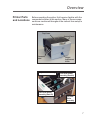
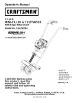
Printer Parts
and Locations
Before operating the printer, first become familiar with the
components shown in this section. Many of these components are mentioned throughout the manual from setup to
maintenance.
Top Cover
Control Panel
Transport
Belts
Entry Roller Assembly
Print Head Holder
Assembly (Bank B)
Height
Adjustment
Knob
Print Head Holder
Assembly (Bank A)
Exit Idler
Roller
Assembly
Overview
Printer Parts
and Locations
(continued)
Parallel Port
Teleco
Connector
Universal Serial
Bus Port
Power Switch
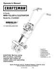
Overview
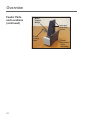
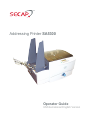
Feeder Parts
and Locations
Outer Fence
Extension
Outer Belt
Fence
Inner Belt
Fence
Feed Rollers
Media
Support
Wedge
Inner Fence
Extension
Feed Ramp
Assembly
Feeder Floor
Assembly
Feed Ramp
Extension
Feeder Locking
Knob
Inner and Outer
Belt Fences
Media Support
Wedge
Feed Ramp
Extension
Feeder
Locking
Knob
Wire Form
Adjustment
Slide
Feed Ramp
Adjustment Bracket
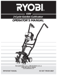
Overview
Feeder Parts
and Locations
(continued)
Media
Support
Wedge
Inner and
Outer Belt
Fences
Feeder
Locking
Knob
10
Feeder
Information
Cable
Assembly
Chapter
2
Setting Up
Your
SA5300 Printer
This chapter explains how to
unpack, assemble and connect
your new printer.
In this chapter:
Choosing a Location.......................2-2
Assembling the Printer...................2-3
1. Install the Feeder......................2-4
2. Install the Gas Shock................2-5
3. Install the Side Guides..............2-6
4. Install the Feed Ramp..............2-6
5. Connecting the Parallel
Cable or USB Cable.................2-8
6. Connect the Power Cord
and Turn ON.............................2-9
7. Install the Bulk Ink
Assembly (Optional)...............2-10
8. Install the Print Cartridge(s).....2-10
Setup
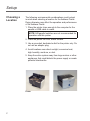
Choosing a
Location
The following environmental considerations must be kept
in mind when selecting a location for the Address Printer.
Doing otherwise may affect the operation and performance
of the Address Printer.
1. Place the printer close enough to the computer for the
parallel or USB cable to reach. NOTE: A/B parallel switches are not recommended for
operation with this printer.
2. Place the printer on a flat, stable surface.
3. Use a grounded, dedicated outlet for the printer only. Do
not use an adapter plug.
4. Avoid locations near direct sunlight, excessive heat,
high humidity, moisture, or dust.
5. Keep the entire system away from large motors or other
appliances that might disturb the power supply or create
potential interference.
Feeder
Printer
Setup
Assembling
the Printer
• Remove the printer and feeder from the boxes they
were shipped in.
• Be sure to remove any accessories from the boxes.
NOTE: Ensure that all packing materials (styrofoam,
tape, etc.) have been removed from the exterior and
interior of the printer and feeder.
Once you've placed the printer and feeder in a suitable
location, assemble the printer and feeder components in
the following order:
NOTE: Do not plug the printer into the power source until
you've completed steps 1-4.
1. Attach the Feeder.
2. Install the Gas Shock.
3. Install the Side Guides.
4. Install the Ramp.
5. Connect the parallel or USB cable.
6. Attach the power cord and turn the printer ON.
7. Install the Bulk Ink Tray Assembly (optional).
8. Install the Print Cartridges.
Setup
Assembling
the Printer
(continued)
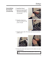
1. Install the Feeder
A.Prop the printer cover
open.
B.Plug the feeder
information cable into
the receptacle on the
printer.
C.Lift the feeder and slide the tangs into the slots on
printer. Push the feeder down until it locks into place.
Slots to
attach feeder
Setup
Assembling
the Printer
(continued)
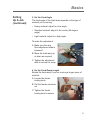
2. Install the Shock
A.Insert the screw through
the hole on the printer
wall and secure with the
bolt provided.
B.Snap the shock onto
the bolt as shown in the
picture at right.
C.Snap the other end of the shock onto the bolt inside the
printer cover.
Properly installed shock
D.Push in the plastic end caps to lock the shock onto each
ball attachment.
NOTE: This cap must be pulled open to remove the
shock.
Setup
Assembling
the Printer
(continued)
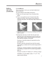
3. Install the Side Guides
Use the screws provided to attach the right and left side
guides to the printer
Installing the left side guide
4. Install the Feed Ramp
A.Remove the quick
release pin at the bottom
of the feed ramp.
B.Slide the wire form
adjustment slide onto the
adjustment bracket.
Installing the right side guide
Setup
Assembling
the Printer
(continued)
C.Line up the feed ramp
on the feeder floor.
Reinsert the quick
release pin to lock the
feed ramp in place.
D.Slide the media support
wedge onto the feed
ramp.
Setup
Assembling
the Printer
(continued)
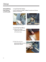
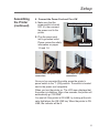
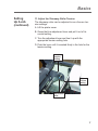
5. Connecting the Parallel Cable or USB Cable
Use the parallel cable to
Parallel
connect the printer to a
port
standard parallel port on
your computer, or use a
USB cable to cnnect the
printer to a USB port on
your computer.
The Address Printer ports
USB port
are located on the rear of
the printer near the power
switch.
Parallel Cable
A. Align the male end of the parallel cable to the port on
the printer. Push the cable connector completely in.
B. Secure the cable in place. Use the two wire clips located
on each side of the Parallel connector to snap into the
tabs on the cable.
C. Align the other end of the cable to the connector on the
computer and push into the port.
D.Secure the cable in place. Use the thumb screws on
the cable connector to screw into the connector on the
computer.
USB Cable
A. Align the squarer end of the USB cable to the USB port
on the printer. Push the cable connector completely in.
B. Align the flatter end of the USB cable to the USB port
on the computer or USB hub. Push the cable connector
completely in.
Setup
Assembling
the Printer
(continued)
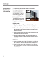
6. Connect the Power Cord and Turn ON
A.Make sure that the
Power plug and receptacle
power switch is turned
OFF (0), then connect
the power cord to the
printer.
B.Plug the power cord
into a grounded outlet.
Please review the safety
information on pages
1-5 and 1-6.
Parallel cable and power cord
connections
Power switch
USB cable and power cord
connections
Once you've connected the cable, press the printer’s
power switch to the “I” (ON) position. The switch is located
next to the power cord receptacle.
When you turn the printer on. The LCD menu displays that
the printer is initializing. After a few seconds, the printer will
automatically go "ON LINE".
You can tell if the printer is ON LINE, by looking at the indicator light above the ON LINE key. When the printer is ON
LINE, the indicator will be lit.
Setup
Assembling
the Printer
(continued)
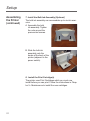
7. Install the Bulk Ink Assembly (Optional)
The bulk ink assembly can accomodate up to six ink reservoirs.
A.Assemble the bulk
ink assembly. Tighten
the nuts around the
premounted screws.
B.Slide the bulk ink
assembly onto the
hooks at the back of the
printer (adjacent to the
power switch).
8. Install the Print Cartridge(s)
The printer uses Print Cartridges which you must now
install before you can print. Follow the instructions in Chapter 5—Maintenance to install the new cartridges.
10
Chapter
3
Printer Basics
In this chapter you'll learn about key
features of the SA5300 printer and
how to adjust it to meet the requirements of your material.
In this chapter:
Setting Up A Job.............................3-2
1. Set the Separator Gap..............3-2
2. Center the Feed Ramp
Under the Material....................3-4
3. Set the Feed Angle...................3-5
4. Set the Feed Ramp Length......3-5
5. Position the Side Guides..........3-6
6. Load Material............................3-7
7. Adjust the Media
Thickness Knob........................3-8
8. Output Stacker..........................3-9
9. Print a Test Piece......................3-9
10.Set the Print Head
Position...................................3-10
11.Adjust the Takeaway Rolller
Tension................................... 3-11
Basics
Setting Up A
Job
Setting up a print job means adjusting the printer to accommodate the width, height, thickness and weight of your
material.
There are two things that determine how reliably your
printer feeds: the setup adjustments and the quality of your
material. A good setup minimizes misfeeds and jams. And
your printer will perform at its best when you run material
that falls within our published specifications. See Appendix
B for complete material specifications.
1. Set the Separator Gap
Whenever you switch from one material type to another,
you need to set the gap between the separators and the
feed roller before printing begins.
There are three positions of the "H" Block:
• Lever fully down - adjusted to media thickness (ready to
operate).
• Lever midpoint - not adjusted to any media (free-floating
on media, not set up to operate).
• Lever fully up - locked in the up position, not adjusted to
any media thickness.
Basics
Setting
Up A Job
(continued)
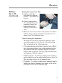
Setting the Proper Feed Gap
A.Unlatch and lift the
lock lever to its highest
position. This raises the
H-Block.
B.Place a sample piece
of material between the
separator fingers (the
lower section of the
H-Block) and the feed
roller.
C.Move the Lock Lever to the central position so that the
H-Block drops onto the material, then push the Lever
down to lock the H-Block in place.
Tips for Setting the Separators
• The blue hex nut has six (numbered) settings. When
one setting wears out, turn the nut to the next setting.
This will extend the life of the feed roller.
• If the material extends partially under the front H-Block
as in the example above, you could temporarily move
the material under both separator fingers of the front
H-Block and set this too. This may help with separation
and feeding of 'difficult' material.
• Filled Envelopes - Try setting a slightly wider separator
gap by adding one or two empty envelopes on top of the
filled envelope used to set the separator gap.
• Postcards - Try setting a slightly wider separator gap by
adding one sheet of standard copy paper on top of the
postcard used to set the separator gap.
Basics
Setting
Up A Job
(continued)
2. Center the Feed Ramp under the Material
A. Loosen the Wireframe
Clamp Knob.
B.Place a sample piece
of material in the feed
area, up against the rear
wall. Center the feed
ramp under your sample
piece of material.
Be sure to set the ramp
in a postion where the
material rests on the
ramp.
Basics
Setting
Up A Job
(continued)
3. Set the Feed Angle
The feed angle of the feed ramp depends on the type of
material you're running:
• Heavy material: adjust to a low angle
• Standard material: adjust to the center (45 degree
angle)
• Light material: adjust to a high angle
To make the adjustment:
A.Make sure the wire
form adjustment slide is
loosened.
B.Move the feed ramp up
or down as required.
C.Tighten the adjustment
slide to secure the ramp.
4. Set the Feed Ramp Length
Extend the feed ramp if you are running a longer piece of
material.
A.Loosen the feeder
locking knob.
B.Pull the feeder extension
out.
C.Tighten the feeder
locking knob to secure.
Basics
5. Position the Side Guides
A.Place a sample piece or
trial stack of material in
the input area.
B.Slide the side guides
until they almost touch
the stack of material.
Check that there's about
1/16 inch (1.5mm)
clearance between the
guides and the stack.
Sideguides
NOTE: Proper clearance is important. If you push
the side guides tight up against the stack, they could
retard feeding and cause jams. If the clearance is too
great, pieces could skew as they feed into the printer.
Basics
Setting
Up A Job
(continued)
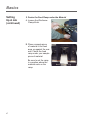
6. Load Material
Once your printer is set up, you can load material and
make a test print.
To avoid misfeeds, follow these instructions:
A.Make sure the input area is free of dust and other
matter.
B.Take a manageable amount of material and while
holding it as shown, fan all sides of the material to
separate each piece. This step helps keep misfeeds to a
minimum.
C.Tamp the material on a flat surface, making sure that the
stack is square.
D.Shingle the stack as you load it into the input area.
Begin with just a few envelopes to start the stack and
get the proper contour, then add several more pieces.
Then add the remainder of the stack.
Envelopes: should be stacked to feed with the left or
right edge first.
Booklets: should be stacked to feed with the sealed
edge leading or stacked with the sealed edge placed to
feed first.
Catalogues: should be stacked to feed with the sealed
edge leading or stacked with the sealed edge placed to
feed first.
Postcards: must be 3.5" (89mm) x 5" (127mm) or larger.
Self-Mailers: may be folded in half or “C” or “Z”. The
media must be tabbed.
Basics
Setting
Up A Job
(continued)
7. Adjust the Media Thickness Knob
The media thickness knob sets the distance between the
Print Heads and the material. Use it to compensate for
different material thicknesses and to increase clarity of the
printing.
Estimate the thickness of the material to be run.
NOTE: All material in a run must be the same thickness.
For 1/16" (1.5mm) thick material, start half way. For 1/8"
(3mm) thick material, start with setting all the way at the
Thick side (clockwise).
Thin
Material
Thick
Material
IMPORTANT! Adjusting the media thickness knob too far
counterclockwise may cause smearing or jamming.
2. While running test samples, close the gap (turn knob
anticlockwise) until the desired quality of printing is
obtained.
Basics
Setting
Up A Job
(continued)
A Note about Print Quality
The printer is designed to feed and print on a range of
materials with various finishes and coatings. However the
sharpness of the print may vary with different materials,
depending on how absorbent the surface is, as well as
other qualities.
You'll get best results using white wove bonded stock.
Printing is less sharp on Tyvek, recycled and glossy material. It is also possible that ink may not dry thoroughly
on certain very glossy materials. Always test high gloss
materials for their drying qualities before you buy them in
quantity and attempt to run a print job.
8. Output Stacker
An optional high capacity power stacker is available for
your printer. Contact Pitney Bowes for more information.
9. Print a Test Piece
A.Make sure material is loaded properly. (Or you can use
a single test piece if you'd like to check that your setup
adjustments are OK.)
B.Turn the printer ON. The ON/OFF switch is located on
the interface panel on the left side of the machine.
C.Press the On Line button on the printer control panel
until the indicator above the button lights.
D.Press the Test Envelope button. A single envelope will
feed and a sample address should print.
E.Check the print quality. If it's not what you want, adjust
the media thickness knob as required and run another
test piece.
Basics
Setting
Up A Job
(continued)
10. Set the Print Head Position
The final step is to adjust and locate the bank of Print
Heads over the media where the images/graphics or text is
going to be printed.
A. Lift the main cover.
B.Loosen the Clamp
Knob. This knob secures
the bank of Print Heads.
C.Slide the knob to move
the bank. Locate the
bank over the area you
wish to print on the
media.
D.Tighten the Clamp Knob
to secure the bank in
place.
E.Repeat steps B-D for the other print head.
F. Close the main cover.
G.Put media in the printer and then press the Test
Envelope button to print a test address. H.Check that this is the location required for printing
on the media. Redo the above steps to make further
adjustments to the location, if necessary.
When you're satisfied with your setup adjustments, you're
ready to run the job. The next chapter explains how to use
the printer with your computer.
10
Basics
Setting
Up A Job
(continued)
11. Adjust the Takeaway Roller Tension
The takeaway roller can be adjusted to one of seven tension settings.
A.Lift the printer cover.
B.Grasp the blue adjustment lever and pull it out of its
current setting.
C.Turn the adjustment lever and line it up with the
appropriate tension setting hole.
D.Push the lever until it is seated firmly in the hole for the
tension setting.
Loosest
tension
setting
Tightest
tension
setting
Adjustment
lever
11
Basics
12
Chapter
4
Using the
SA5300 with
Your Computer
This chapter includes instructions
for installing the SA5300 printer
driver, selecting the printer from a
computer application, and using
the SA5300 printer driver. Additional information is available in
the Bryce Printer Driver manuals
packed with your printer.
In this chapter:
Installing the Printer Driver ............4-2
Selecting the Printer
From a Windows Application..........4-3
Making the SA5300 Driver the Default
Print Driver......................................4-3
Accessing the Print Driver..............4-4
The General Tab.............................4-4
Printing Preferences.......................4-4
Using the Printer with Your Computer
Installing the
Printer Driver
Before you can use your printer with your computer, you
must install the Appropriate printer driver. The driver gives
your computer information about the printer you're using,
and tells the printer about the settings you want to use in
your print job.
If you have not previously installed the printer driver on
your computer, refer to the installation instructions furnished with it.
Using the Printer with Your Computer
Selecting
the SA5300
Printer From
a Windows
Application
The following steps explain how to select the SA5300
printer from a Windows software application. The steps
are similar for most applications. You can also refer to your
application's documentation for specific instructions on
installing printer drivers and selecting printers.
1. Start the software application that you use when printing
envelopes with the SA5300 printer and open the file you
want to use.
2. From the File menu, select Print.
The Print dialogue box appears.
3. Click on the arrow in the printer Name box.
A drop-down list box appears containing the names of
the available printers.
4. Select Bryce 30K (The driver for the SA5300 Printer).
Click OK to send the job to the printer.
Once you've made this selection, your print jobs will automatically go to the SA5300 printer when you select File/
Print. Remember to change the printer selection back to
your regular printer for your other printing jobs.
Making the
SA5300 the
Default Print
Driver
1. From the Start Menu, select Settings.
2. Click on Printers.
3. Right Click on the Bryce 30K icon.
4. Click on Set as Default Printer. A check mark appears
next to the Bryce 30K icon.
Using the Printer with Your Computer
Accessing the
Print Driver
1. From the Start Menu, select Settings.
2. Click on Printers.
3. Right-click on the Bryce 30K icon.
4. Click on Properties. The Printer Properties dialog box
displays.
The General
Tab
The window displays information about your printer and allows you to enter its location and any comments.
Click on Print Test Page to test printer operation.
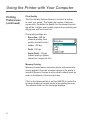
Printing
Preferences
Click on Printing Preferences to set up advanced options.
The Printing Preferences window displays. From there you
may select the following tabs:
The Paper Tab
The Paper tab options allow you to select the envelope
size and to identify the way the envelope will enter the
printer.
Paper Size
This refers to the size of
the envelope you plan to
use for your mailing. The
SA5300 handles a wide
range of envelope sizes.
Use the drop-down menu to
make your selection.
Using the Printer with Your Computer
Printing
Preferences
(continued)
Orientation
Orientation refers to the way the envelope is placed in the
printer. There are two orientation options:
• Normal - The envelope is placed vertically in the printer
feeder tray with the flap side down and the top fold of
the envelope resting against the side of the feeder wall.
The short side of the envelope is then correctly positioned for the SA5300 to print the destination address in
the standard location on the envelope.
• Inverted - Refers to feeding an envelope in backwards,
i.e., rotating it 180 degrees from the normal position.
When an envelope is inverted on the SA5300 printer,
it is oriented so the flap side is down and the flap edge
faces the back of the printer. Select Inverted when you
want to print a return address and/or when you are printing on the left side of an oversized envelope.
Once you've made your selection, click on OK to confirm it.
Click the Feature tab to make additional printer settings.
The window shown on the next page displays.
The Features Tab
The Features tab options allow you to set a feed delay,
select the printing quality, and turn on memory overlay.
Feed Delay
Use the Feed Delay feature to increase (or decrease) the
time between the printing of envelopes. This feature is
especially helpful when you are having a problem with ink
smearing. Increasing the Feed allows the ink to set before
the next envelope is printed.
Using the Printer with Your Computer
Printing
Preferences
(continued)
Print Quality
The Print Quality feature allows you to select a setting
to meet your needs. The higher the number of dots per
square inch, the better the quality, but the slower the printing will be. A higher print quality requires more printing and
drying time and uses more ink.
Print quality settings are:
•Executive: 600 dpi
(slowest printing, best
quality, shortest ink life)
• Letter: 300 dpi
• Draft: 200 dpi
• Super Draft: 150 dpi
(fastest printing, lightest
characters, longest ink life)
Memory Overlay
Memory Overlay feature improves printer performance by
storing graphics from the envelope design in the printer’s
memory. Memory Overlay is active when a check mark appears in the Memory Overlay check box.
Click on the Advanced tab to set the SA5300 to pause the
envelope feeding at certain points in the printing process.
The window shown on the next page displays.
Using the Printer with Your Computer
Printing
Preferences
(continued)
The Advanced Tab
Settings in the Advanced tab provide a means to pause the
envelope feeding at certain points in the printing process.
Options include:
Pause on Tray Break
This option allows you to remove printed envelopes designated for a given tray from the printer and place them into
the tray.
Pause on Package Break
This option allows you to remove a given number of printed
envelopes from the printer and bundle them into a package.
Using the Printer with Your Computer
Chapter
5
Printer
Maintenance
This chapter describes the
procedures you should perform to
keep your printer running troublefree.
In this chapter:
Replacing the Print Cartridges.......5-2
Prolonging the Life of Print
Cartridges.......................................5-6
Cleaning.........................................5-7
Preventive Maintenance.................5-7
Print Quality Problems....................5-7
Cleaning the Sensor.......................5-8
Cleaning the Exit and Entry Idler
Rollers. ..........................................5-9
Cleaning the Wipers.....................5-10
Cleaning the Transport Belts
and Floor Assembly.....................5-10
Printer Maintenance
Replacing
the Print
Cartridges
Removing Old Print Cartridges
WARNING! The ink in the cartridge may be
harmful if swallowed. Keep new and used cartridges out of reach of children. Discard empty cartridges immediately.
When the Ink indicator shows 5% or lower, the Print Cartridges are nearly empty and have to be changed soon.
The On Line indicator will flash to remind you of the situation. Use the following steps to remove used or damaged
Print Cartridges.
1. Make sure the printer is OFF LINE. With the printer on,
press the On Line key until the indicator light above the
key goes out.
2. Lift the main cover.
3. Grasp the blue cartridge
latch and lift it up. The
cartridge will “pop”
loose.
4. Hold the handle on the
ink cartridge and lift
the cartridge out of the
cradle.
Printer Maintenance
Replacing
the Print
Cartridges
(continued)
Installing New Print Cartridges
1. Make sure the printer is OFF LINE. With the printer on,
press the On Line key until the indicator light above the
key goes out.
2. Lift the main cover.
3. Remove the Cartridge
from the shipping container by peeling the top
cover off. Be careful not
to touch the copper ribbon.
4. Gently remove both
pieces of tape covering the ink nozzles on
the Print Cartridge. Be
careful not to touch the
copper nozzles.
5. Raise the latch all the
way up on the Head
Print Assembly. Hold
the cartridge from the
notched handle on top
of the cartridge. Gently insert the cartridge
down at approximately a
45 degree angle into the
cradle.
Printer Maintenance
Replacing
the Print
Cartridges
(continued)
6. Push down on the ink cartridge until it is seated on the
bottom of the Head Print Assembly. Push and rock the
ink cartridge forward to stand the ink cartridge up.
7. Press down the blue latch to lock the ink cartridge in
place.
8. Repeat this process to load the other ink cartridges.
NOTES:
• Reset the Ink Count in the Main Menu after replacing
a Print Cartridge.
• Make a test print after replacing a Print Cartridge. If
"stepping" or misalignment is apparent, realign the
cartridges using the Adjust Print function described
on page A-26.
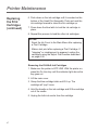
Removing the Old Bulk Ink Cartridges
1. Make sure the printer is OFF LINE. With the printer on,
press the On Line key until the indicator light above the
key goes out.
2. Lift the main cover.
3. Grasp the blue cartridge latch and lift it up. The
cartridge will “pop” loose.
4. Hold the handle on the ink cartridge and lift the cartridge
out of the cradle.
5. Unplug the bulk ink nozzle from the cartridge.
Printer Maintenance
Replacing
the Print
Cartridges
(continued)
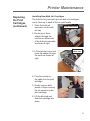
Installing New Bulk Ink Cartridges
The bulk ink tray can hold up to six bulk ink cartridges;
one to hook up to each of the six print heads.
1. Stack the bulk ink
Route cables here
reservoirs on the bulk
ink tray.
2. Route (up to three
cables) through the
notches on either side
of the bulk ink assembly
as shown at right.
3. Lift the printer cover and
route the cables through
the notch as shown at
right.
Route
cables here
4. Plug the nozzle on
the cable into the print
cartridge.
5. Gently remove both
pieces of tape covering
the ink nozzles on the
print cartridge
6. Lift the blue tab and
slide the cartridge into
place.
Printer Maintenance
Prolonging
the Life
of Print
Cartridges
Included in the Accessories are Cartridge Capping Assemblies. These are designed to enclose the Print Cartridge
nozzles. Proper use of the Cartridge Capping Assemblies
helps to maintain good print quality and prevents ink from
drying and clogging the Print Cartridge nozzles.
Use the Cartridge Capping
Assemblies when the printer
is left to idle or shut down
for more than a few minutes.
1. Remove the Print
Cartridge from the
Print Heads assembly.
(See page 5-2 for information on removing the Print
Cartridges.)
NOTE: Keep the Print Cartridge in order or numbered
otherwise the counter for the percent ink remaining
will give false information.
2. Remove any excess ink
on the nozzles.
3. Clean any ink buildup
on the rubber seal of
the Cartridge Capping
Assembly to prevent
it from obstructing the
nozzles.
4. Install the Print Cartridge
nozzle first into the
Cartridge Capping
Assembly, then press the
top section completely in.
5. Remove the Print Cartridge from the Cartridge Capping
Assembly in reverse order.
Suggestion: Check the Print Head Alignment and
perform a purge of the Print Cartridges before operating
the printer.
Printer Maintenance
Preventive
Maintenance
Cleaning
The SECAP™ SA5300 Ink Jet Printer is designed for
trouble- free service with a minimal amount of care. You
should schedule regular cleaning of the items covered in
this chapter.
CAUTION! Clean Print Cartridges, ink surfaces and covers with plain water only. (Water
works best!)
Clean all rubber rollers with isopropyl, denatured or rubbing alcohol only.
Use of any other cleaning solvents will damage the rollers.
Keep petroleum-based cleaning solvents
away from rubber or plastic parts. Anything but
alcohol will cause premature breakdown of the
rubber compound.
Print Quality
Problems
If print quality is unacceptable, try the following:
• From the Main Menu, select Purge Print Head. The
purging process clears any clogged ink on the print
nozzles. Often this returns the print quality to a normal
level. See Appendix A, Control Panel Menus, for
information on using this feature.
• Clean the print heads on each Print Cartridge.
Remove the cartridge as described on page
5-2. Dampen a soft cotton cloth with water
and wipe the nozzles clean (wipe in the proper
directions).
• Install a new Print Cartridge (page 5-3).
Printer Maintenance
Cleaning the
Sensor
With use, a film and/or dust builds up on the eye of the
sensor causing misfeeds of media. Periodically use compressed air to blow dust from the sensors. For caked on
dust use a Q-tip to remove the dust from the eye of the
sensor.
NOTE: The lower half of the sensor is seen through the
holes in the floor.
Upper
sensor
Lower
sensor
Printer Maintenance
Cleaning the
Exit Idler and
Entry Rollers
From normal operations of the printer the Exit Idler Rollers and Entry Rollers will accumulate a buildup of ink,
wax, etc. which will require removal or the idlers will leave
marks on the media.
Use water to dampen a soft cotton cloth to remove the ink
from the rollers.
Entry rollers
Exit idler rollers
Printer Maintenance
Cleaning the
Wipers
The wipers beneath the banks of print cartridges will, over
time, pick up ink, wax, clay and other material from the
media it touches. Once enough of this material accumulates on the wipers, it will leave marks or smears on the
media.
1. Loosen the Print Head Assembly locating screw.
2. Swivel the Print Head
Assembly up and back
to expose the wipers.
(You may need to
move the Print Head
Assembliy to the front or
rear to gain clearance
to swivel the assembly
fully back).
3. Use water to dampen a soft cloth to remove any ink,
wax, clay, etc. and keep the wipers clean.
Cleaning the
Transport
Belts and
Floor
Assembly
Ink will get sprayed on the transport belts and the floor
assembly from all the purging, setting up and printing
records, etc. Eventually enough ink will accumulate on the
Transport Belts to give them a glossy sheen.
Use water to dampen a soft cotton cloth to remove ink
from the Transport Belts and the Floor Assembly.
NOTE: Raise the Print
Head Assemblies up and
out of the way to clear
the Floor Assembly.
10
Chapter
6
Troubleshooting
Your Printer
This chapter lists some common
printer problems and offers
suggestions on how to fix them.
In this chapter:
Problems and Solutions.................6-2
Feed Problems...............................6-2
Print Quality Problems....................6-3
Interface Problems.........................6-6
Motor Problems..............................6-6
Other Problems..............................6-6
Troubleshooting Your Printer
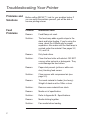
Problems and
Solutions
Before calling SECAP™, look for your problem below. If
you can solve the problem yourself, you will be able to
resume printing sooner.
Feed
Problems
Problem Intermittent Feed
Reason:
Feed Ramp not used.
Solution:
The feed ramp adds a gentle slope to the
stack and helps feeding. If you're using the
ramp, check the H-Block gap for proper
separation. Also make sure the feed ramp is
centred under the material. See pages 3-2,
3-3, and 3-4.
Reason:
Dirty feed rollers.
Solution:
Clean the feed roller with alcohol. DO NOT
use any other solvents or detergents. They
could damage the feed rollers.
Reason:
Paper dust present (yellow or white residue), blocking feed sensor.
Solution:
Clean sensor with compressed air (see
page 5-3).
Reason:
Too much material in feeder (too heavy).
Weight of stack must be 18lbs. or less.
Solution:
Remove some material from stack.
Reason:
Media out of specification.
Solution:
Refer to Appendix B - Specifications.
Reason:
Media sticking together.
Solution:
Fan media before loading.
Troubleshooting Your Printer
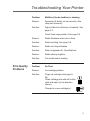
Print Quality
Problems
Problem
Multifeed (feeds doubles) or skewing
Reason:
Separator (H-block) not set correctly. Also
ramp set incorrectly.
Solution:
Adjust H-block to thickness of material. See
page 3-3.
Check feed ramp position. See page 3-4.
Reason:
Media thickness knob set too thick.
Solution:
Reduce setting. See page 3-8.
Reason:
Media out of specification.
Solution:
Refer to Appendix B - Specifications.
Reason:
Media sticking together.
Solution:
Fan media before loading.
Problem
No Print
Reason:
Ink cartridge problem.
Solution:
Purge ink cartridge (see page A25).
Clean cartridge jets with soft cotton cloth and water (in the direction
shown).
Change to a new cartridge(s).
Troubleshooting Your Printer
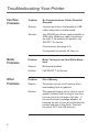
Print Quality
Problems
(continued)
Problem
Grey or Light Print–Black Ink
Reason:
Ink supply is low, or media thickness knob is
set too high.
Solution: Check adjustment of the media thickness
knob (page 3-8). If this fails to correct the
problem, replace ink cartridge (page 5-2).
Problem
Address Printing is not Sharp
Reason:
Incorrect media thickness knob setting.
Also, unsuitable material.
Solution:
Check whether media thickness knob is
adjusted too high (page 3-8).
NOTE: Print quality is less sharp when using Tyvek, recycled or glossy media.
Problem
Address Smudging
Reason:
Incorrect media thickness knob setting.
Also, ink may not dry on very high gloss
material.
Solution:
Check whether media thickness knob is
adjusted too low (page 3-8). Try using less
glossy material.
Check exit idler rollers.
Troubleshooting Your Printer
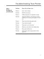
Print Quality
Problems
(continued)
Problem
Skewed Print
Reason:
Sliding fence set incorrectly.
Solution:
Fence should control media without restricting feed.
Reason:
Roller or wiper is running along the edge of
the media.
Solution:
Move the print head bank to a slightly different position over the media.
Problem
Unwanted Bolding
Reason:
Escape sequence turning on bold or bold
selection in printer's menu options is set to
bold.
Solution:
Turn off bolding in software and/or turn bold
selection in printer menu OFF. See Appendix A for instructions. If problem still exists,
call Pitney Bowes for service.
Problem
Addresses "Walking"
Reason:
Incorrect Address Setup.
Solution:
Count carriage returns and line feeds and
adjust Lines Per Address to the same number.
Reason:
Address Termination should be Form Feed.
Solution:
Set Address Setup for 8 lines.
Check Line Termination: Typical:
CR=CR; LF=LF. Other choices,
(CR=CR+LF;LF=LF), (CR=CR;LF=CR+LF),
(CR=CR+LF;LF=CR+LF)
Troubleshooting Your Printer
Interface
Problems
Motor
Problems
Other
Problems
Problem
No Communications; Printer Does Not Respond
Reason:
Incorrect print driver, bad parallel or USB
cable, bad printer controller board.
Solution:
Use SA5300 print driver; replace parallel or
USB cable. Make sure cable connections
are tight. If the problem still persists, call
SECAP™ for service.
Clear memory (see page A-3).
Cycle power (turn printer off, then on).
Problem
Motor Turning but no Feed Roller Movement
Reason:
Mechanical problem.
Solution:
Call SECAP™ for Service.
Problem
Out of Memory
Reason:
The printer can run out of memory when
downloading fonts or graphics.
Solution:
This generally means you’re trying to use a
graphic (artwork) that’s too big or you have
too many fonts or too large a font size. If
the out-of-memory message appears, try
reducing the size of your art and limiting the
number and size of your fonts. Then turn
the printer OFF, then ON and retry.
Troubleshooting Your Printer
Other
Problems
(continued)
Problem
Paper Out or Paper Jam
Reason:
Input area is empty.
Solution:
Refill the input area.
Reason:
H-Block separator not adjusted correctly.
Solution:
Adjust the H-Block to the thickness of the
material you're running. See pages 3-2 and
3-3.
Reason:
Paper jam obstructing paper path.
Solution:
Clear obstructed path.
Reason:
Paper jam in exit roller area.
Solution:
Make sure exit rollers are rotating freely.
Reason:
Dirty paper feed sensor.
Solution:
Clean sensor with compressed air. See
page 5-8.
Troubleshooting Your Printer
Appendix
A
Using the
Control Panel
Menus
Use the printer menus to control
how your printed material looks.
This appendix describes each
menu and its options.
In this appendix:
Using the Control Panel................ A-2
Using the Menus........................... A-3
Using the Main Menu ................... A-5
Using the Setup Menu................. A-16
Using the Service Menu.............. A-28
Printer Menus
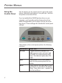
Using the
Control Panel
Use the buttons on the control panel to get to the printer
menus, define the print options, run a print job, and turn
the printer on line and off line.
If you’ve installed the SA5300 printer driver on your
computer, you’ll normally perform these actions from
within the application you’re using to set up your envelope layout. These settings will override the control panel
settings.
The buttons on the control panel perform the following
functions:
This Button...
On Line
Eject
Menu
Does This...
Toggles (switches) between ON
LINE (communicates with host) and
OFFLINE (no communications with
host). The indicator lights when ONLINE.
When printer is OFFLINE, press to
eject the last printed piece from the
printer.
Press once for the Main Menu. Press
and hold for 2 seconds for the Setup
Menu. Press Menu and – together for
the Service Menu.
Printer Menus
Using the
Control Panel
(continued)
Using the
Menus
This Button...
Enter
Does This...
Press to select the currently displayed menu option.
When in a menu, press to scroll for+
ward through the menu options.
_
When in a menu, press to scroll backwards through the menu options.
Test Envelope When the printer is OFFLINE, prints
a test envelope. This is very useful
when you set up a print job.
The printer has three menus that can be displayed on
the operator panel:
• The Main Menu controls how your printed material
looks.
• The Setup Menu is used to configure your printer so it
will function correctly with your computer.
• The Service Menu is used to align the print cartidges.
NOTE: The printer must be OFFLINE in order to
access the menu options.
Printer Menus
Using the
Menus
(continued)
To select an option:
1. Press the On Line button until the indicator goes out
(showing the printer is Off Line).
2. To access the Main Menu, press the Menu button.
To access the Setup Menu, press and hold the Menu
button for two (2) seconds until SETUP MENU is
displayed.
To access the Service Menu, press and hold the
Menu button and the – button simultaneously until
SERVICE MENU is displayed.
3. Press the plus (+) or minus (–) buttons to move
through the list of menu options.
4. When the appropriate menu option appears, press
the Enter button to display the choices associated
with that option.
5. Press + or – to scroll through the choices. When an
option has an asterisk (*) in front of it, it means that
option is presently selected.
Upon receipt of the printer from the factory, the
asterisk is typically the default setting.
When you press the Enter button to define a new
option, an asterisk will appear before the selected
option.
6. Press the Menu button several times to back out
of the Menu until the printer displays its normal
operating screen. Then press the On Line button to
print.
Printer Menus
Using the Main
Menu
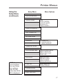
The Main Menu options are:
1. Address Layout
2. Print Quality
3. Font
4. Barcode
5. Address Recovery
6. Clear Counter
7. Job Settings
8. Conveyor Time
9. Image Overlay
10.Purge Print Head
11.Reset Ink Counter
NOTE: The settings you define in a Windows™ software application override any settings you choose in
the printer menus.
Printer Menus
Using the
Main Menu
(continued)
NOTE: If Orientation is set to Inverted, Address Layout
option A will be
“Distance to right”.
Main Menu
Menu Options
1. ADDRESS LAYOUT
A.
B.
C.
D.
DIST FROM LEFT
DIST FROM TOP
LINE SPACING
ORIENTATION
2. PRINT QUALITY
EXECUTIVE
LETTER
DRAFT
SUPER DRAFT
3. FONT
A.
B.
C.
D.
E.
F.
4. BARCODE
A. LOCATION
B. 5 DIGIT ON/OFF
C. BAR WIDTH
5. ADDRESS RECOVERY
A. GET ADDRESS
B. CLEAR MEMORY
NAME
SIZE
WIDTH
BOLD
ITALIC
OUTLINE
6. CLEAR COUNTER
7. JOB SETTINGS
A. LOAD
B. SAVE
8. CONVEYOR TIME
9. IMAGE OVERLAY
10. PURGE PRINT HEAD
11. INK COUNT
A. FIRST IMAGE OVERLAY
B. CLEAR OVERLAY
C. PRINT OVERLAY FIRST
Printer Menus
Using the
Main Menu
(continued)
1. Address Layout
Use the Address Layout option to set up the way an address appears on the printed material.
Define the following options from this menu:
A. Distance from Left/Distance to Right
• Distance from Left. This menu item only appears when the Orientation is set to Normal. It
allows you to change the position of the record
horizontally on the media. Records will appear
upside down when viewed from the front of the
printer. Press the + or – buttons to increase or
decrease the distance from 0 to 13.5" (342mm).
Press the Enter button to select the desired
measurement.
• Distance to Right.
NOTE: If Orientation is set to Inverted, Address
Layout option A will be “Distance to right”.
This menu item only appears when the Orientation is set to Invert. It allows you to change the
position of the record horizontally on the media.
Records will appear right side up when viewed
from the front of the printer. Press the + or
– buttons to increase or decrease the distance
from 0 to 13.5" (342mm). Press the Enter button to select the desired measurement.
Distance from Left
Distance to Right
Printer Menus
Using the
Main Menu
(continued)
1. Address Layout (continued)
B. Distance from Top
This menu item allows you to change the position of the
record without moving the bank of Print Cartridges. The
printer achieves this by reducing the available area used
for printing. Therefore, increasing the setting decreases
the print area. The recommended setting for Distance
From Top is 0.00.
Press the + or – buttons to increase or decrease the
Distance from Top from 0 to 3.0". Press the Enter button
to enable the desired measurement.
C. Line Spacing
Press the + or – buttons to increase or decrease the Line
Spacing (i.e., 3, 4, 6, 8 lines/inch or Automatic), defined
in lines per inch. Automatic line pitch selection is based
on industry-standard definitions for line spacing for each
print pitch and style selected. The printer will automatically select the correct setting for the font and size of the
characters being printed.
D. Orientation
The choices are Normal and Inverted.
Select Normal for most applications. This tells the printer
that the bottom edge of the material is against the Rear
Chassis Assembly. The print will appear upside down
when viewed from the front of the printer.
The Inverted option tells the printer that the top edge of
the material is against the Rear Chassis Assembly. The
print will appear right side up when viewed from the front
of the printer.
NOTE: If Orientation is set to Inverted, Address Layout
option A will be “Distance to right”.
For instructions how to use the menus and select an option, refer to page A-4.
Printer Menus
Using the
Main Menu
(continued)
2. Print Quality
This option changes the number of dots sprayed to
print characters or graphics on the media. Changing the
amount of ink sprayed also affects how fast the Transport Belts are capable of running. The display will show
the new item whenever the Print Quality is changed.
These menu items are available in the printer driver and
override the control panel settings.
Executive
This is the darkest of the four print qualities. It prints at
the slowest speed, uses the most ink and delivers the
best quality printout.
Letter
Letter quality is used for envelopes that require a finished, polished appearance.
Draft
Draft quality will print documents fast and save ink.
Super Draft
This is the lightest of the four and prints at the fastest
speed.
For instructions how to use the menus and select an option, refer to page A-4.
Printer Menus
Using the
Main Menu
(continued)
3. Font Selection
The SA5300 has 12 internal fonts. All fonts are scalable from 4 to 30 point size, in 5 width settings, and can
be printed in regular, bold, italic and outline style. The
SA5300 also supports downloaded fonts. This means
that if you are using Windows, all the fonts installed in
Windows are available. The options on this menu are:
A. Name
The printer has 12 internal fonts available: Courier, Sans
Serif, Roman, Baxter, Dingbat, Hancock, Marina, Quincy,
Silicon, Springer, Stencil and Windmill.
B. Size
The font size (internal or external) can be set from 4 to
30 point.
C. Width
The font width is normal (100%), thin (75%), condensed
(50%), wide (125%) or expanded (150%).
D. Bold
This is the darkest imprint because character stroke
weight (thickness of print) is increased. Use Bold to emphasize or highlight text in an address.
E. Italic
Italic characters have decreased stroke weight, print at
an oblique angle and print somewhat lighter than standard or bold typefaces. Use italic to emphasize and add
flair to address text that requires a finished, polished
appearance.
F. Outline
Use this option to print only the outline or the edge of the
font’s shape.
10
Printer Menus
Using the
Main Menu
(continued)
4. Barcode
Use this option to print a USPS barcode. The options on
this menu are: A. Location, B. 5 Digit On/Off, and C. Bar
Width.
A. Location
Use this option to print the barcode above or below the
address, or to stop printing the barcode.
• Above Address prints the barcode in the address
block above the first line of the address.
• Below Address prints the barcode below the last line
of the address.
• Off stops the barcode from printing.
B. 5 Digit On/Off
Use this option to print a 5 digit barcode for a 5 digit ZIP
Code.
NOTE: Only a five digit barcode is printed for a 5 digit
ZIP Code. A Delivery Point Barcode cannot be generated from a five digit ZIP Code.
C. Bar Width
Use this option to increase the width or decrease the
width of the bars generated for the USPS Postnet and
Planet barcodes. Select this item to counteract the variance in the barcodes due to material, print quality, inks,
etc. Bar width settings run from 6 to 12.
11
Printer Menus
Using the
Main Menu
(continued)
5. Address Recovery
Use this option to direct the printer’s memory to go back
a certain number of addresses when an error occurs in
order to reprint the address. The options on this menu
are: A. Get Addresses; and B. Clear Memory.
A. Get Addresses
Select Get Addresses after a jam is cleared and you
want to restart printing at the point where the printer left
off just before the jam occurred.
To retrieve any address in the data buffer, press the
Enter button. The first 16 characters of the first line of
the last address printed will be displayed on the LCD.
If NONE TO RECOVER appears, there is no data in
the memory to print. Press the + or – buttons to scroll
through the addresses. When the desired address appears, press the Enter button to print that address plus
the remaining addresses in the buffer.
B. Clear Memory
Clear Memory should be selected before you start a new
batch printing. This is required since the memory will
contain up to twenty addresses from the previous batch.
An alternative way to clear the memory is to press the +
and – buttons simultaneously.
For instructions how to use the menus and select an option, refer to page A-4.
12
Printer Menus
Using the
Main Menu
(continued)
6. Clear Counter
Clear Counter should be selected before you start a new
printing batch. This resets the counter on the display to
zero.
For instructions how to use the menus and select an option, refer to page A-4.
7. Job Settings
The Printer can hold eight job presets in memory. This
eliminates the need for changes to the printer setup
when you change print jobs. The options on this menu
are: A. LOAD; and B. SAVE.
A. Load
Select this option to retrieve a previous job setup. Press
+ (for more) or – (for less) to increase or decrease the
desired job number. Press the Enter button to select the
desired option.
B. Save
Use this option to save the current envelope setup (address position, barcode position, number of lines per
inch, and so on). The printer saves the setup as a job
number (1 to 8). Press + (MORE) or – (LESS) to increase or decrease the desired job number. Press the
Enter button to select the desired option.
13
Printer Menus
Using the
Main Menu
(continued)
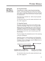
8. Conveyor Time
This setting can only used if the model of conveyor
stacker being used supports this function. This item increases the length of time the stacker will stay on. It can
be set from 0.00 to 2.00 seconds.
Generally, when the print quality is set higher than draft,
and/or, print width is larger than normal, the drying time
of printed records must be increased to prevent smearing or smudging of addresses. Changing the time that
the conveyor remains on alters how the media is shingled on the conveyor.
Special consideration of ink drying time and media handling for glossy or Tyvek media should also be considered when using a conveyer.
9. Image Overlay
This menu item is used in conjunction with the Overlay Printer Driver. Use this option to print ‘static’ text or
graphics in the same location on every piece. The Image
Overlay option is best used for printing a company logo
and return address.
A. First Image Overlay
This option saves the very first record or graphic received into the printers’ memory as an overlay.
B. Clear Overlay
This option clears the overlay data in the printer’s memory.
C. Print Overlay First
This option prints the data sent for the overlay onto the
first piece. Use this piece to verify the location of the
overlay is correct.
For instructions how to use the menus and select an option, refer to page A-4.
14
Printer Menus
Using the
Main Menu
(continued)
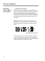
10.Purge Print Head
This menu item is used to clean the ink jet cartridge
nozzles. The purge process fires all the ink jet nozzles
onto a piece of media to dislodge and clear any dried ink
on the print nozzles. Often this will return the print quality
to a normal level.
Once the purge is started, the – button may be pressed
to stop the cycle.
For instructions how to use the menus and select an option, refer to page A-4.
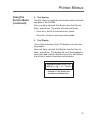
11.Reset Ink Counter
The printer calculates the amount of ink used by each
of the Print Cartridges. When the On-Line (green LED)
starts to blink it is a signal that one or more of the Print
Cartridges is less than 5% full and it must be changed
relatively soon. After new Print Cartridges are installed
the Ink Count needs to be reset to stop the green LED
from blinking.
This item displays the estimated amount of ink remaining
in the print cartridge(s).
Press the + plus or – minus button to scroll through the
print cartridges 2, 3, 4, 5, and 6. When the desired Print
Cartridge number is displayed, press the Enter button to
reset the percent ink to 100%.
Estimated amount of ink remaining
Print Cartridge No.
5% INK IN HEAD
1+
ENTER TO RESET
–
Press Enter when a new cartridge is
installed to reset percentage to 100%
Press + or – to scroll Print
Cartridge Nos. up or down
For instructions how to use the menus and select an option, refer to page A-4.
15
Printer Menus
Using the
Setup Menu
To access the Setup Menu, the printer must be OFF
LINE. If the printer is ON LINE, press the On Line button once so the indicator above the button turns off.
Then, press and hold the Menu button for two seconds
to display the Setup Menu.
The Setup Menu options are:
1. Stop on Feed Err (Error)
2. Feeder Signal
3. Lines Per Address
4. Line Termination
5. Hex Dump Mode
6. Language
7. Transport Speed
8. Postal Bundle Break
9. Pre-Purge
10.Feed Gap
11.ROM Revision #
12.Print Head Size
16
Printer Menus
Using the
Setup Menu
(continued)
Setup Menu
Menu Options
1. STOP ON FEED ERR
2. FEEDER SIGNAL
NONE
ON/OFF CONTROL
PULSE OFF SIGNAL
ON/QUICK OFF
SIGNAL POLARITY
3. LINES PER ADDRESS
4. LINE TERMINATION
5. HEX DUMP MODE
6. LANGUAGE
A. SYMBOL SET
B. INCH/MILLIMETER
C. MENU LANGUAGE
7. TRANSPORT SPEED
NOTE: To print
a list of the Main
Menu and Setup
Menu settings,
press the Test
button when ROM
REV is displayed.
8. POSTAL BUNDLE BRK
ENABLE/DISABLE BREAK
BREAK CHARACTER
BREAK CHAR COUNT
PAUSE TIME
9. PRE-PURGE
PURGE AT START
PERIODIC PURGE
PURGE INTERVAL
NOZZLE KEEP ALIVE
10. FEED GAP
SELECTABLE GAP
STREAM FEEDING
11. ROM REVISION #
12. PRINT HEAD SIZE
17
Printer Menus
Using the
Setup Menu
(continued)
1. Stop On Feed Err (Error)
Use this option to stop the printer from feeding more
media when an error occurs. Otherwise the printer will
continuously feed media until the record is accurately
printed before continuing onto the next record. Stopping the printer when an error occurs is helpful when the
media is in short supply.
For instructions how to use the menus and select an option, refer to page A-4.
2. Feeder Signal
The Feeder Signal option is for feeders that work with
5 volt DC signals. The printer will signal to the feeder
when it receives one or more records. If an error occurs when the Stop On Feed Error option is enabled the
feeder signal will be cleared to stop the feeder.
A. None
This option disables the feeder signal.
B. On/Off Control
This option turns a signal on whenever one or more records are in the buffer to be printed. The signal is turned
off once the last record in the buffer is being printed. The
signal will also turn off when an "Early Feed Error" occurs while the Stop On Feed Error option is enabled.
C. Pulse Off Control
This option turns on a signal when:
• the sensor detects the leading edge of the envelope
for the last address to be printed at the print heads or
• when an early feed error is detected (if the Stop On
Feed Error option has been selected).
In either case, the signal will be cleared one second
later.
18
Printer Menus
Using the
Setup Menu
(continued)
2. Feeder Signal (continued)
D. On/Quick Off
This option turns on a signal whenver one or more
reocrds are in the buffer to be printed. The signal is
turned off once the sensor detets the piece to print the
last record of the buffer on.
E. Signal Polarity (Active On/Active Off)
This option reverses the signal used to trigger the feeder.
• Active On actives and external feeder by switching
on the feeder signal.
• Active Off activates an external feeder by switching
the feeder signal off.
For instructions how to use the menus and select an option, refer to page A-4.
3. Lines Per Address
Use this option to set the number of lines of text in the
address field. It can be set from 1 to 66.
For instructions how to use the menus and select an option, refer to page A-4.
4. Line Termination
This item allows the printer to interpret what the Line
Termination (end of a line of text) is for different operating systems or software. Choose from the various Line
Termination formats to get the correct line count and
then the record will print correctly.
The typical software line termination is CR = CR;
LF = LF. If your software is not typical then the Line
Termination can be modified. The menu choices are (CR=CR;LF=LF), (CR=CR+LF;LF=LF),
(CR=CR;LF=CR+LF), and (CR=CR+LF;LF=CR+LF).
19
Printer Menus
Using the
Setup Menu
(continued)
5. Hex Dump Mode
The information provided here is for those of our customers who are technically inclined.
The Hex Dump Mode option causes the printer to print
all commands and data it receives from the computer
in a hexadecimal format. Use this feature to check the
integrity of your data. When you enable this option,
instead of addresses printing, a Hex dump of the data
stream prints on the material. To use this option, the
printer must be attached to a computer.
This chart can be easily understood by memorizing five
Hex codes: Capital A is 41 Hex, numbers are 30’s (0 is
30 Hex, 1 is 31 Hex etc.), Carriage Return (CR) is 0D,
Line Feed (LF) is 0A and Form Feed is 0C.
When Hex Mode is disabled, a typical address will be
printed on a single envelope. When Hex Mode is enabled, the same address will be printed on several envelopes (3 to 5) because Hex codes are two digits each
separated by brackets. Since a capital letter A is a Hex
[41], there are 4 elements printed for each character of
the address.
When reviewing addresses printed in Hex mode, start
from the end of the address and count backward toward
the beginning of the address. Count the number of CRs
[0D] and LFs [0A]. Verify that the printer’s address setup
has the same number of CRs and LFs as the address
printed. If there is a variation in the number of CRs or
LFs between addresses, then the address MUST be terminated with a (form feed) FF [0C] (within the data sent
to the printer).
When you’re finished using this option, use the Menu
button to back out of the menu until the printer displays
its normal operating screen. Then press the On Line
button and send addresses to the printer.
20
Printer Menus
5. Hex Dump Mode (continued)
X
DE
C
MSB
HE
Using the
Setup Menu
(continued)
LSB
0
16
32
48
64
80
96 112
0
1
2
3
4
5
6
7
0
0
NUL
DLE
SP
0
@
P
`
p
1
1
SOH
DC1
!
1
A
Q
a
q
2
2
STX
DC2
"
2
B
R
b
r
3
3
ETX
DC3
#
3
C
S
c
s
4
4
EOT
DC4
$
4
D
T
d
t
5
5
ENQ
NAK
%
5
E
U
e
u
6
6
ACK
SYN
&
6
F
V
f
v
7
7
BEL
ETB
′
7
G
W
g
w
8
8
BS
CAN
(
8
H
X
h
x
9
9
NT
EM
)
9
I
Y
i
y
10
A
LF
SUB
*
:
J
Z
j
z
11
B
VT
ESC
+
;
K
[
k
{
12
C
FF
FS
,
<
L
\
l
|
13
D
CR
GS
–
=
M
]
m
}
14
E
SO
RS
•
>
N
^
n
-
15
F
SI
US
/
?
O
_
o
DEL
You should keep a record of these setups and the number you assigned. You can press the Test button to print
out the current menu settings.
NOTE: If your printer is attached to a computer, use
this menu to configure your printer so it is compatible
with your computer’s setup.
For instructions how to use the menus and select an option, refer to page A-4.
21
Printer Menus
Using the
Setup Menu
(continued)
6. Language
The SA5300 has several language sets installed. The
options on the language menu are: A. Symbol Set; B.
Inch/Millimeter; C. Menu Language.
A. Symbol Set
The symbol set contains the International Standards Organization (ISO) character set substitution tables. They
include the following:
ISO 6 ANSI ASCII
ISO 69 FRENCH
ISO 21 GERMAN
ISO 4 UK
ISO 60 NORW/DAN
ISO 11 SWED/FIN
ISO 15 ITALIAN
ISO 17 SPANISH
ISO 61 NORW/DAN
ISO 10 SWED/FIN
ISO 16 PORTUGUESE
ISO 8859
Roman 8
WINDOWS LATIN 1
PC 8
CP 1250
B. Inch / Millimeter
This option selects the printer Measurement system
– Inch or Millimeter.
C. Menu Languages
This option changes the LCD control panel menu to the
language you want. Supported languages are English,
German, French, Italian, Spanish, Dutch, Polish and
Japanese.
For instructions how to use the menus and select an option, refer to page A-4.
22
Printer Menus
Using the
Setup Menu
(continued)
7. Transport Speed
Select this item to slow down the transport of the media to increase drying time for the ink and assist in the
handling and sorting of the media by decreasing the
throughput. Varying the speed of the printer will not affect the print quality. This item can be set from 50% to
100%.
For instructions how to use the menus and select an option, refer to page A-4.
8. Postal Bundle Brk (Break)
A. Enable/Disable Break
This option will stop the printer for a few seconds before
proceeding to print the rest of the records. This allows
time for bundling the presorted records together and
separates the bundle from the next batch of records being sent to the printer. Use the menus to customize the
command to suspend operation and to set how long the
printer must wait before it resumes operating.
Select the type of command the printer must receive before it stops feeding to set a gap between batches while
it is operating. The marker to set a break consists of the
repetition of a single character appearing on a single line
to start the printer to pause.
The Example below shows the use of three (3) “#” symbols to initiate a break:
###
**************23
XYZ Company
123 Any Road
Anytown, CT 06470-1234
23
Printer Menus
Using the
Setup Menu
(continued)
8. Postal Bundle Brk (Break) (continued)
B. Break Character
This option sets what character the printer must receive
before it will momentarily halt working. The list of characters to select from are:
!”#$%&’()*+-./
0123456789
:;<=>?@
ABCDEFGHIJKLMNOPQRSTUVWXYZ
These characters and symbols range from [! ASCII (33)]
to [Z ASCII (90)] in an ASCII Table.
NOTE: Send the [SOH ASCII (01)] character to trigger
a Postal Bundle Break.
C. Break Char Count
Set the number of occurrences the character or symbol
must appear in succession before the printer can send a
Postal Bundle Break signal. This item can be set from 01
to 10.
D. Pause Time
Set the length in seconds for the printer to sit idle before
sending another piece of media. This item can be set
from 0.00 to 31.75 seconds.
For instructions how to use the menus and select an option, refer to page A-4.
24
Printer Menus
Using the
Setup Menu
(continued)
9. Pre-Purge
Use this option to keep the print heads from drying out
and to clear the inkjet nozzles automatically while operating the printer.
A. Purge at Start
If you have long breaks of twenty seconds or more
before starting another batch of records, this option will
purge on the first piece before printing the records.
B. Periodic Purge
This option will activate the periodic purge.
C. Purge Interval
This option will purge the ink cartridges at timed intervals on a piece. Set the time to determine when to
purge the ink cartridges. The printer will pause for a few
seconds after the purge pattern is printed. Each timed
interval begins from the last purge print pattern. This
item can be set from 020 to 240 seconds.
D. Nozzle Keep Alive
This option will randomly purge the individual nozzles
of the print cartridges to keep the ink from clogging the
nozzles and to create a virtually invisible pattern of dots
on the media. The printer will continually purge except
when another pre- purge is pending and while the records are being printed.
For instructions how to use the menus and select an option, refer to page A-4.
25
Printer Menus
Using the
Setup Menu
(continued)
10.Feed Gap
Two settings are available to modify how the printer
reacts. Use this option to help when feeding very glossy
media or short media.
A. Selectable Gap
This item increases the gap or space between pieces
of media as they are fed through the printer. Increasing
the gap will slightly reduce the overall throughput of the
printer. This item can be set from 3.1" to 12.7".
B. Stream Feed
This option gives the each record a fixed time before
printing on the next piece. This option is best used to
print small records of three or less lines of text.
Enabling this option will disable the ‘Selectable Gap’ setting above.
For instructions how to use the menus and select an option, refer to page A-4.
11.ROM Revision
This option is extremely useful whenever it is necessary
to verify the Firmware Revision installed in the printer.
It is also useful to determine if your printer requires an
upgrade.
The Maintenance Count, which is the total number of
print cycles accumulated, is also displayed. This information is helpful in determining solutions to printer
problems.
If you press the Test button when ROM REV. is displayed on the LCD, a list of the Main Menu and Setup
Menu settings is printed on four pieces of media.
For instructions how to use the menus and select an option, refer to page A-4.
26
Printer Menus
Using the
Setup Menu
(continued)
12.Print Head Size
Enable this option for the printer to keep track of the ink
usage correctly for the type of ink supply you are using.
Select the type of Print Cartridge being used with the
printer. Changing the Print Head Size alters how the
percentage of ink used is calculated for the menu item
12, RESET INK COUNT.
For a standard cartridge, select NORMAL CAPACITY.
If you use the high capacity ink reservoir system, select
EXTENDED CAPACITY.
For instructions how to use the menus and select an option, refer to page A-4.
27
Printer Menus
Using the
Service Menu
To access the Service Menu, the printer must be OFF
LINE. If the printer is ON LINE, press the On Line button
once so the indicator above the button turns off. Then,
press and hold the Menu button and – button simultaneously to display the ServiceMenu.
The Setup Menu is used by an operator to adjust the
alignment of the print cartridges using the ‘Adjust Print’
function. (The other two functions available—"Test System" and "Test Display"— are primarily intended for use
by a Pitney Bowes Service Representative.)
1. Adjust Print
Use this function to adjust the alignment of the three
print cartridges if ‘stepped’ or misaligned prints are seen.
A. Head 2 up down
B. Head 3 up down
C. Head 5 up down
D. Head 6 up down
Use options A through D to vertically synchronize the
individual Print Cartridges.
Example: Print out an adjust print Test Pattern by
pressing the Test button while in the Adjust Print menu.
The printer will print a Test Pattern like this:
Head 3 is printing too high
28
Printer Menus
Using the
Service Menu
(continued)
1. Adjust Print (continued)
In this example, the crooked line in the center indicates
Print Cartridge No.3 has to have the printer perform a
vertical print adjustment. The example shows Print Cartridge No.3 is too high.
Scroll through the Adjust Print menu options until the
HEAD 3 UP DOWN option is displayed on the LCD
panel.
Enter the menu option to move the setting down. Enter
the new value into the printer’s memory. A value between
280 and 300 can be entered. The higher the value, the
higher the relevant cartridge will print. An Asterisk (*) will
appear in front of the new selection.
Press the Test button to print another Test Pattern. The
Test Pattern is printed using the entered selection.
When the correct numeral is selected the center Test
Pattern will be one long ‘zig-zag’ line with hatch marks
like the example below.
Head 3 is now correctly aligned
E. Head 2 side to side
F. Head 3 side to side
G. Head 5 side to side
H. Head 6 side to side
Use the options E through H to horizontally synchronize
the individual Print Cartridges.
29
Printer Menus
Using the
Service Menu
(continued)
1. Adjust Print (continued)
When a line of print is split apart, or the left edge of a
block of lines don’t line up with the left edge of the other
lines, the Print Cartridges have to be synchronized
horizontally. Perform a horizontal adjustment whenever
the wide solid line and the set of 18 thin vertical lines do
not form long vertical lines for the whole bank of Print
Cartridges.
Example: Print out an adjust print Test Pattern by
pressing the Test button while in the Adjust Print menu.
The printer will print a Test Pattern like the example
below:
Head 2 misaligned horizontally
In the example above the wide vertical line on the left
and 18 thin vertical lines indicate Print Cartridge No.2
needs a horizontal print adjustment. The example shows
Print Cartridge No.2 is too far to the right.
30
Printer Menus
Using the
Service Menu
(continued)
1. Adjust Print (continued)
Scroll through the Adjust Print menu options until the
HEAD 2 SIDE TO SIDE option is displayed on the LCD
panel. Select this menu item to change the settings.
Press the – button to scroll the values down and move
Head 2 left. Press the Enter button to select the desired
value. An Asterisk (*) will appear in front of the new selection.
Press the Test button to print another Test Pattern. This
time the Test Pattern is printed using the entered selection.
Heads now aligned horizontally
When the setting is correct, the wide line and the set of
18 vertical lines form long vertical lines down the entire
bank of Print Heads.
31
Printer Menus
Using the
Service Menu
(continued)
1. Adjust Print (continued)
I. Bank A to Sensor/Bank B to Sensor
• Bank A to Sensor - Use this option to set the
distance between the sensor and the first head in
Bank A.
• Bank B to Sensor -Use this option to set the
distance between the sensor and the first head in
Bank B.
Set the Test Pattern printed by the bank of Print Heads
to locate the vertical bar 1/2 inch from the edge of the
media.
Example: Print out an adjust print Test Pattern by
pressing the Test button while in the Adjust Print menu.
The printer will print a Test Pattern like the example
below.
Edge of media
Measure
this distance
The distance from the leading edge of the media to the
leading edge of the heavy bar on the Test Pattern should
be 1/2 inch.
If the measurement is incorrect, change the ‘offset’ setting using the + or – buttons, then press the Enter button
to select the desired value. An Asterisk (*) will appear in
front of the new selection.
Take another test print and measure again. If necessary,
repeat the process until you obtain the leading edge
margin of 1/2 inch.
32
Printer Menus
Using the
Service Menu
(continued)
2. Test System
Use this option to check the mechanical and/or electrical
operation of the SA5300.
Once you have selected Test System from the Service
Menu, press Enter. The printer will enter test mode.
• Press the + button to increase motor speed.
• Press the - button to decrease motor speed.
3. Test Display
Use to help determine if the LCD display is not functioning properly.
Once you have selected Test Display from the Service
Menu, press Enter. The display will scroll the alphabet in
lower case and numbers across the top line, and bottom
line will scroll control characters and numbers.
defghijklmnopqrstuvwxyz 0123
!#$%&*()_+- =[] : ; ' <> / ? 01234
Example of LCD display with
characters scrolling across.
33
Printer Menus
34
Appendix
B
SA5300
Specifications
This Appendix contains detailed
hardware and material specifications for the SA5300 printer.
In this Appendix:
Equipment Specifications.............. B-2
Material Specifications.................. B-5
Specifications
Equipment
Specifications
Physical Dimensions
16" (406.4mm) high; 30" (762mm) wide; 24" (609.6mm)
deep
Weight
87 lbs. (39.5 kg), including accessories
Electrical
Voltage: 120 volts AC +/- 10%. Other selectable voltages:
100v, 220v, and 240v
Frequency: 60 Hz +/- 3 Hz automatic frequency selection
for other voltages
Fuse Type: 2 x 2 Amp Slow-Blow
Power Consumption: 126 Watts, 430 BTU/hr.
Agency Approvals
SECAP™ USA certifies that the Address Printer complies
with the Low Voltage Directive 73/23/EEC and
the EMC Directive 89/336/EEC. The product was
tested in a typical configuration.
Interface
Centronics Parallel and USB
Control Language
PCL5, modified
Driver Compatibility
Windows 2000, XP
Address Recovery
Memory buffer holds a maximum of 99 addresses
Specifications
Equipment
Specifications
(continued)
Print Modes/Print Resolution
• Super Draft: 600 x 150 DPI
• Draft: 600 x 200 DPI
• Letter: 600 x 300 DPI
• Executive:
600 x 600 DPI
Resident Fonts
Courier, Sans Serif, Roman, Baxter, Dingbat, Hancock,
Marina, Quincy, Silicon, Springer, Stencil, and Windmill.
(All fonts are scalable from 4 to 30 pt size.)
Resident Font Enhancements
• Bold
• Expanded
• Outline
• Condensed
• Italic
Downloadable Fonts
Supports TrueType downloadable fonts.
User-Definable Parameters
• Font Characteristics
• Address Placement
• Print Quality
Throughput
Maximum 30,000 pieces per hour, depending on print
mode, media size, number of address lines, and barcode imprinting. Throughput may vary depending on
machine condition and operator skill.
Effective Print Area
The printable width of print line is 13.5" (343mm). The
maximum printable height is 15" (380mm).
Specifications
Equipment
Specifications
(continued)
Printhead/InkJet Cartridges
Cartridges: User-replaceable ink jet. Available are: Single
‘Standard’ Black Ink Cartridge; Single ‘Versatile’ Ink Cartridge; and a High Capacity Ink Reservoir System.
Contact SECAP™ to order.
Environmental Limits
Operating Conditions:Temperature—55 to 95°F (12 to
35°C);
Humidity—8 to 80%
Storage Conditions: Temperature—42 to 100°C (5 to
40°C);
Humidity—10 to 90%
Noise Level
Idle Mode: <6.6 Bel (A)
Operating Mode: <7.3 Bel(A)
Operator position: no more than 65 dBa referenced to 20
µpa.
Recommended Usage
SECAP™ has tested this machine under many different
conditions, and recommends that you do not exceed the
usage levels specified below:
• Typical monthly usage is 500,000 pieces. Maximum
monthly throughput is 1,000,000 pieces.
NOTE: Usage beyond these recommended cycles
is not covered under your Equipment Maintenance
Agreement.
• Yearly usage is 6,000,000 pieces.
• Product life is 5 years or 30,000,000 cycles (whichever
comes first).
Specifications
Material
Specifications
Approved Media
The paper types listed below are approved for use with
the SA5300 Printer. Please note that the dimensional
limits above apply in all cases, and that all media (flats,
envelopes, postcards, catalogue envelopes, etc.) must
be without windows, unstuffed and unsealed.
• White Wove
• Card stock
• Bond paper
• Brown kraft
• Recycled paper
• Manila
• Coated paper
Media Sizes
Minimum: 3" (76mm) x 5" (127) mm; Maximum: 13"
(330mm) x 15" (390mm). Thickness: 0.003" (0.076mm)
to 0.5" (12.7mm). Also see the table on the next page.
Material Notes
Envelopes have a flap along the long edge and are processed by the printer non-flap edge first. Envelopes may
have either a diagonal or straight edge along the envelope flap. Stuffing materials must be machine folded or
cut sheets.
Booklets are defined as media having physical dimensions 6" (152mm) x 9" (229mm) or larger. Booklets have
an opening along their long edge which is covered by a
flap with an adhesive seal.
Catalogue envelopes have an opening along their short
edge which is closed by a flap with an adhesive seal.
Postcards have no folds or bends. The printable side
may have a higher surface roughness than the nonprintable side.
Self-mailers may be of "C," "Z," or 1/2-folded construction. They may not exceed the maximum allowable
thickness as specified on the previous page and must
Specifications
Material
Specifications
(continued)
be tabbed per postal regulations. 1/2 and tri-folds must
be machine produced.
A catalog may consist of multiple pages bound by adhesive or tabs on the feed edge or at 90 degrees with
respect to the feed edge.
Sheet stock may consist of 60 to 105 g/m2 bond as well
as 227 to 302 g/m2 coated stock. The size and thickness
constraints specified above apply.
Table of Envelope Sizes
Name
Style
Dimensions (Inch)
Height x Width
Dimensions (Metric)
Height x Width
#6-1/4
#6-1/2
Square
#6-3/4
Commercial
#8-1/2
Square
#4
Baronial
#5
Baronial
#5-1/2
Baronial
#6
Baronial
#7-3/4
Official
#7
Official
#8-5/8
Official
#9
Official
#10
Official
#11
Official
#12
Official
#14
Official
Monarch
C4
DIN C4
C5
DIN C5
C6
DIN C6
DL
3-1/2 x 6"
6-1/2 x 6-1/2"
3-5/8 x 6-1/2"
8-1/2 x 8-1/2"
3-5/8" x 5-1/8"
4-1/8 x 5-5/8"
4-3/8 x 6-3/4"
4-3/4 x 6-1/2"
3-7/8 x 7-1/2"
3-3/4 x 6-3/4
3-5/8 x 8-5/8"
3-7/8 x 8-7/8"
4-1/8 x 9-1/2"
4-1/2 x 10-3/8"
4-3/4 x 11"
5 x 11-1/2"
3-7/8 x 7-1/2"
9 x 12-3/4"
6-3/8 x 9"
4-1/2 x 6-3/8"
4-3/8 8-11/16"
89 x 152 mm
165 x 165
216 x 165
261 x 261
92 x 130
105 x 142
110 x 171
121 x 165
98 x 190
95 x 171
92 x 219
98 x 225
104 x 241
114 x 263
120 x 279
127 x 292
98 x 190
229 x 324
162 x 229
114 x 162
110 x 220
Appendix
C
Glossary
This Appendix contains a glossary
of terms related to your Address
Printer and Computer.
Glossary
Cable
Wires that carry the information between the computer and the printer.
Centronics parallel interface
A device for connecting printers and other peripheral devices to a computer. It
transmits a full byte at a time.
Character
A printable letter or symbol.
Character height
The height of a uppercase letter. A character height is measured in points.
Characters per inch
The number of characters printed in a horizontal inch. Also called pitch.
Character set
The set of characters or symbols that make up a language.
Clean print cartridge
Describes the process of removing dried ink from the nozzles of the ink jet cartridge.
Configuration
The settings used by the printer to communicate with the computer. Also the
internal settings in the printer that control the print job.
Control code
The instructions sent to the printer to describe how to perform the print job.
Control panel
The buttons and display that are used to manually change the printer’s settings.
Cpi
See characters per inch.
Data communications
The sending of data from the computer to a peripheral device, i.e., the printer.
Dots per inch
The number of ink dots printed in one horizontal inch. The larger the number the
better the resolution of print.
Glossary
Double feeding
A condition in which two or more pieces of media feed at the same time or without separation.
DPI
See dots per inch.
Draft quality
A lower print resolution which saves ink and allows faster printing of a document.
Drivers
A file used by the computer’s software to communicate commands and information that the printer needs to layout and print a document.
Embedded printer commands
Commands sent in a record or document to instruct the printer to change printing
options.
EPROM
Electronic Programmable Read Only Memory.
Escape character
A special non-printable character (ESC ) used to instruct the printer to change
printing options.
Escape sequence
Commands sent beginning with the escape character that instruct the printer to
change printing options: fonts, page orientation, etc.
Feed gap
Adjustable opening between the ends of the H-Block Assembly fingers and the
Feed Rollers so the media is fed one at a time.
Font
A set of printable characters with consistent style and characteristics.
Grounded
A electrical circuit that has a voltage of zero.
Handshaking
A method for the computer to communicate with peripheral devices to ensure
complete transfer of information.
Hex dump
A printer option that allows all the information and commands sent to the printer
as base 16 digits.
Glossary
Internal test address message
The preprogrammed Address that is printed when the Test button is pressed.
Interface cable
The cable that connects the printer or other device to the computer.
Interface connector
The connectors on both ends of the interface cable that insert into the interface
ports.
Internal fonts
Resident or built-in fonts supplied with a printer.
Jam
See Paper Jam.
Letter quality
Print resolution which saves ink and still provides a high quality document.
Lines per inch
The number of lines printed in one vertical inch.
Menu directories
The list of available printer controls that appear on the bottom of the LCD display.
A directory can contain other directories called "sub-directories."
Off Line
A condition in which the printer will not respond to information sent from the computer.
On line
A condition in which the printer will accept and respond to information sent from
the computer.
Outline fonts
Scaleable printer fonts.
Paper jam
A condition in which media is stuck in the printer.
Parity
An error checking method used when communicating between the computer and
a peripheral device.
Glossary
PCL commands
A standard printer language of commands to access printer features or options.
Point size
A measurement standard for the height of a printed character. One point equals
one seventy-second of an inch.
Port
See Printer Interface Port.
Postal regulations
Rules and guidelines set up by the Postal Authority for mail.
Power socket
The socket on the back of the printer where the line cord is connected.
Print cartridge
A removable container that holds ink for printing.
Print quality
Refers to the resolution or level of sharpness of the printed image.
Printer driver
See Drivers.
Record
A collection of related fields that make up the name and address of an individual
in a mailing list file.
Sans serif
A font typeface that contains no serifs or finishing strokes on the top or bottom of
the characters. Helvetica and Arial are examples of sans serif typefaces.
Scaleable fonts
Outline printer fonts that are stored in a mathematical form and can be enlarged
or reduced.
Spacing
The relative spacing between characters.
Stuffed media
Media that is already filled and sealed for delivery.
Glossary
Subdirectory
A directory within a directory (or a folder within a folder).
Troubleshooting
The process of isolating and correcting a problem.
Universal Serial Bus (USB)
A communications protocol for connecting printers and other peripheral devices
to a computer. This protocol supports automatic device detection for "plug and
play" installation. It also it supports daisy chaining and branching for hot plugand-play capability without disturbing running applications. USB also supports
the SBP (serial bus protocol) which allows data transfers to PC peripherals. SBP
allows bigger files to be sent asynchronously across the bus.
There are several USB standards, the latest of which, 2.0, supports communications up to 480 mb/sec.
The maximum recommended distance of a peripheral to a PC is 16 feet or 5
meters.
Index
Index
A
E
Addresses "Walking" 5
Address Smudging 4,5
Approved Media 5
Assembling the Printer 3
Electrical
Specifications 2
Envelope Sizes
Listing of 6
Executive Print Quality 9
B
Barcode 11
Options, Setting with Menu 11
Bold Type
Unwanted 5
Bulk Ink
installing cartridges 5
removing cartridges 4
C
Cables, Printer
Connecting 8
Recommended types and length 3
Cartridge
Fonts 3
Cleaning
Precautions 7
Preventive Maintenance 7
Printer Floor 10
Print Head Cartridge 7
Sensor 8
Wipers 10
Clear Memory 12
Control Panel Buttons
2,3
CPU
Recommended 3
D
Distance to Bottom 8
Distance to Right 7
Downloadable Fonts 3
F
Feed
Angle, Setting 5
Fence, Positioning 6
Gap, Setting 3
Problems 2
Ramp
centering under material 4
setting length 5
Roller Doesn't Move 6
File Menu
Selecting Printer from 3
Fuzzy Printing 4
G
Get Addresses 12
Glossary 2,3,4,5,6
Glossy Material
Print Quality 9
H
Heavy Material 5
Hex nut 3
I
Important Safety Notes 4,5
Inch/Millimeter 24,25,26,29,32
Using Menu to Select 24,25,26
Ink Jet Cartridge
Installing 10,2,3
Installing
Ink Jet Cartridge 10,2,3
Index
Installing the Printer Driver 2
Interface
Centronics Parallel 2
Interface Problems 6
J
Jam
Paper 7
L
Letter Print Quality 9
Light Material 5
Light Print 4
Line Spacing 8
Loading Material 7
Location, Choosing, for printer 2
M
Main Menu Options
Address Layout 7
Barcode 11
Print Quality 9
Material
Loading 7
Material Notes 5
Media Thickness Knob
Adjusting 8
Memory, Recommended 3
Menu Languages 22
Misfeeds 3
Motor Problems 6
Multifeed (Feeds Doubles) 3
N
No Communications 6
No Print 3
O
Operating Systems that support DA400 3
Orientation 8
Out of Memory 6
Output Stack Height 9
P
Paper Jam 7
Paper size
selecting 4
Parallel
Cable, Connecting 8
Port, Cable Length 3
Port, Location of 8
Petroleum Based Cleaning Solvents 7
Physical Dimensions 2
Power
Cord, Connecting 9
Cord, Receptacle Location 9
Preventive Maintenance 7
Print
Cartridge, Installing Bulk Ink 5
Cartridge, Removing Bulk Ink 4
Cartridge, Replacing 2
Cartridges, Prolonging Life of 6
Driver Installation 2
No printing 3
Quality 9,9
Quality Problems 7,3,4
Test Piece 9
Print Driver
accessing 4
installing 2
making DA950 the default 3
Printer
Assembly 3
Does not Respond 6
memory overlay 6
Index
Parts and Locations 7
preferences 4
print quality 6
properties window 4
Print Head
Position, Setting 10
Printhead
Purging 7
Printhead/InkJet Cartridge 4
Printing
Light 4
Not Sharp 4
Print Modes (Print Resolution)
Available 2
Print Quality
Setting with Menu 9
Problems and Solutions 2
Prolonging the Life of Print Cartridges 6
R
Recycled Material
Print Quality 9
Resident Font Enhancements 3
Resident Fonts
Listing 3
ROM Revision Number 28
Using Menu to View 28
S
Safety Information 5
Selecting the DA950 Printer From a Windows Application 3
Separator Gap 2
Tips for Setting 3
Setup Adjustments
Feed Fence 6
Media Thickness Lever 8
Separator Gap 2
Setup Menu
ROM Revision Number 28
Setup Menu Graphic 17
Setup Menu Options
ROM Revision Number 28
Shingling
Stack 7
Skew
Avoiding 6
Smudging
Address 4,5
Specifications
Approved Media 5
Cartridge Fonts 3
Downloadable Fonts 3
Electrical 2
Envelope Sizes 6
Fonts 3
Interface 2
Material Notes 5
Physical Dimensions 2
Printhead/InkJet Cartridge 4
Print Modes (Print Resolution) 2
Resident Font Enhancements 3
Resident Fonts 3
Throughput 3
User-Definable Parameters 3
Stacker
Output 9
Standard Material 5
System Requirements 3
Index
T
Test page
printing a 4
Test Piece 9
Printing 9
Throughput 3
Troubleshooting 1
Addresses "Walking" 5
Address Printing is not Sharp 4
Address Smudging 4,5
Intermittent Feed 2
Motor Turning but no Feed Roller Movement 6
Multifeed (Feeds Doubles) 3
No Communications; Printer Does Not
Respond 6
No Print 3
Out of Memory 6
Paper Out or Paper Jam 7
Unwanted Bolding 5
Tyvek
Print Quality 9
U
Unwanted Bolding 5
USB Cable
Connecting 8
User-Definable Parameters 3
Using the Menus 3,4,5,6,7,8,9,10,11,12,13
,14,15,20,21
Using This Guide 2
TM
10 Clipper Road
Conshohocken, PA 19428-2721
www.secapusa.com
For Service & Supplies
Contact your authorized SECAP dealer:
SV61687 Rev. A 8/06
SECAP, located in suburban Philadelphia, is a market leader in providing leading-edge mailing technologies.
SECAP markets a full line of desktop inkjet addressing printers, production and integrating addressing systems,
mailing software, folding and inserting equipment, and tab and label affixing machines throughout North America.
For sales information, call SECAP at 1.800.523.0320 or visit www.secap.com.
Printed on recyclable paper