1
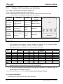
FWDE / SXE Series
Indoor Units
Outdoor Units
AWSI-SXE009-N11
AWAU-YBDE009-H11
AWSI-FWDE012-N11
AWSI-SXE012-N11
AWSI-FWDE018-N11
AWSI-SXE018-N11
AWAU-YBDE012-H11
AWAU-YBDE018-H11
AWSI-FWDE024-N11
AWAU-YBDE024-H11
REFRIGERANT
R410A
SM FWDE/SXE 1-A.1 GB
Version:1
June - 2014
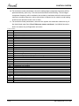
LIST OF EFFECTIVE PAGES
LIST OF EFFECTIVE PAGES
Note: Changes in the pages are indicated by a “Revision#” in the footer of each effected page
(when none indicates no changes in the relevant page). All pages in the following list represent
effected/ non effected pages divided by chapters.
Dates of issue for original and changed pages are:
Original ....... 01 ........ June 30, 2014
Total number of pages in this publication is 52 consisting of the following:
Page
No.
Revision
No. #
Page
No.
Revision
No. #
Page
No.
Revision
No. #
* Zero in this column indicates an original page.
A
SM FWD 1-A.1 GB
TABLE OF CONTENTS
Table of Contents
1.
INTRODUCTION ............................................................................................................................. 1-1
2.
PRODUCT DATA SHEET ............................................................................................................... 2-1
3.
RATING CONDITIONS ................................................................................................................... 3-1
4.
OUTLINE DIMENSIONS ................................................................................................................. 4-1
5.
ELECTRICAL DATA ....................................................................................................................... 5-1
6.
WIRING DIAGRAMS....................................................................................................................... 6-1
7.
REFRIGERATION DIAGRAMS ...................................................................................................... 7-1
8.
CONTROL SYSTEM ....................................................................................................................... 8-1
9.
EXPLODED VIEWS AND SPARE PART LISTS ............................................................................ 9-1
SM FWDE/SXE 1-A.1 GB
i
INTRODUCTION
1.
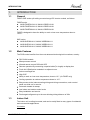
INTRODUCTION
1.1
General
FWDE /SXE series split celling mounted range DC Inverter models, as follows:
FWDE sereis:
AWSI-FWDE012-N11// AWAU-YBDE012-H11
AWSI-FWDE018-N11// AWAU-YBDE018-H11
AWSI-FWDE024-N11// AWAU-YBDE024-H11
FWDE is designed to have the ability to work on low room temperature down to
1212℃
SXE series:
1.2
AWSI-SXE009-N11// AWAU-YBDE009-H11
AWSI-SXE012-N11// AWAU-YBDE012-H11
AWSI-SXE018-N11// AWAU-YBDE018-H11
Main Features
The FWD series benefits from the most advanced technological innovations, namely:
DCI R410A models
Microprocessor control
Infrared remote control RC8 with LED
Remote operation By connecting a special cable(7m length) to display box
Fresh Air & Distribution treated air to adjacent room
Indoor centrifugal fan
High COP
Ability to work on Low room temperature, down to 12℃ (for FWDE only)
Cooling operation at outdoor temperature down to -10℃
Easy access to the interconnecting tubing and wiring connections, main control
panel can slide out for service
Automatic treated air sweep
Low indoor and outdoor noise levels
Easy installation and service
Precharged refrigerant up to the max allowing tubing distance of 20m
1.3
Indoor Unit
The indoor unit is cellingl mounted, and can be easily fitted to many types of residential
and commercials applications.
It includes:
SM FWDE/SXE 1-A.1 GB
1-1
INTRODUCTION
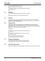
Coil with hydrophilic aluminum fins.
Motorized flaps (two step motors)
Advanced electronic control box assembly (DCI storm)
Mounting plate
1.4
Filtration
The FWDE / SXE series presents several types of air filters:
Easily accessible, and re-usable pre-filters (mesh)
1.5
Control
The microprocessor indoor controller, and an infrared remote control, supplied as
standard, provide complete operating function and programming. For further details
please refer to the Operation Manual.
1.6
Outdoor Unit
The outdoor units can be installed as floor or wall mounted units by using a wall
supporting bracket. The metal sheets are protected by anti- corrosion paint work
allowing long life resistance. All outdoor units are pre-charged. For further information
please refer to the Product Data Sheet, Chapter 2.
It includes :
Compressor mounted in a soundproofed compartment :
Axial fan.
Outdoor coil with hydrophilic louver fins for RC units.
Outlet air fan grill.
Service valves” flare” type connection.
Interconnecting wiring terminal block.
1.7
Tubing Connections
Flare type interconnecting tubing to be produced on site.
For further details please refer to the Installation Manual.
1.8
Inbox Documentation
Each unit is supplied with its own installation, operation and remote control manuals.
1-2
SM FWDE/SXE 1-A.1 GB
INTRODUCTION
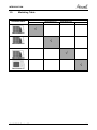
1.9
Matching Table
OUTDOOR UNITS
AWSI-SXE009-N11
INDOOR UNITS
AWSI-FWDE012-N11
AWSI-FWDE018-N11
AWSI-SXE012-N11
AWSI-SXE018-N11
AWSI-FWDE024-N11
√
AWAU-YBDE009-H11
√
AWAU-YBDE012-H11
√
AWAU-YBDE018-H11
√
AWAU-YBDE024-H11
SM FWDE/SXE 1-A.1 GB
1-3
PRODUCT DATA SHEET
2.
PRODUCT DATA SHEET
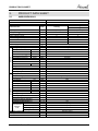
2.1
AWSI-SXE019-N11
Model Indoor Unit
Model Outdoor Unit
Installation Method of Pipe
AWSI-SXE009-N11
AWAU-YBDE009-H11
Flared
Units
Capacity (1)
Pdesign
SEER /SCOP (2)
Energy efficiency class
Annual energy consumption
Tbiv
Tol
Power supply
Circuit breaker rating
Fan type & quantity
Fan speeds
H/M/L
(3)
Air flow
H/M/L
External static pressure
Min-Max
Sound power level (4)
H/M/L
Sound pressure level(5)
H/M/L
Moisture removal
Condensate drain tube I.D
Dimensions
WxHxD
Weight
Package dimensions
LxWxH
Packaged weight
Stacking height
Refrigerant control
Compressor type, model
Fan type & quantity
Fan speeds
H/L
Air flow
H/L
(4)
Sound power level
H/L
Sound pressure level(5)
H/L
Dimensions
WxHxD
Weight
Package dimensions
LxWxH
Packaged weight
Stacking height
Refrigerant type
Refrigerant charge (standard
connecting
tubing per
length)
Additional charge
1 meter
kW
kW
W/W
OUTDOOR
INDOOR
Characteristics
Liquid line
Suction line
Max.tubing length
Max.height difference
Operation control type
Heating elements
Others
Connections
between
units
SM FWDE/SXE 1-A.1 GB
kWh
oC
oC
V/Ph/H
z
A
RPM
m3/hr
Pa
dB(A)
dB(A)
l/hr
mm
mm
kg
mm
kg
units
RPM
m3/hr
dB(A)
dB(A)
mm
kg
mm
kg
units
kg(5m)
gr / 1m
In.(mm)
In.(mm)
m.
m.
Heating
Average
2,5 (1,4-3,6)
3,2 (1,5-4,5)
2.5
2.5
5.25
3.45
A
A
167
1014
N/A
-7
N/A
-15
220-240V/Single/50Hz
16
Centrifugal x 2
760/670/500
400/350/300
0
54
42/37/29
1
16
820x630x190
21
920x726x273
25
7
EEV
Single-rotary DC Inverter
Axial x 1
830
1760
61
51
795x610x2905
38
920x726x273
42
3
R410A
1.1
NA
1/4" (6.35)
3/8"(9.53)
20
10
Remote control
Cooling
kW
2-1
PRODUCT DATA SHEET
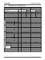
2.2
AWSI-FWDE012-N11, AWSI-SXE012-N11
Model Indoor Unit
Model Outdoor Unit
Installation Method of Pipe
Units
Capacity (1)
Pdesign
SEER /SCOP (2)
Energy efficiency class
Annual energy consumption
Tbiv
Tol
Power supply
Circuit breaker rating
Fan type & quantity
Fan speeds
H/M/L
Air flow (3)
H/M/L
External static pressure
Min-Max
Sound power level (4)
H/M/L
(5)
Sound pressure level
H/M/L
Moisture removal
Condensate drain tube I.D
Dimensions
WxHxD
Weight
Package dimensions
LxWxH
Packaged weight
Stacking height
Refrigerant control
Compressor type, model
Fan type & quantity
Fan speeds
H/L
Air flow
H/L
Sound power level(4)
H/L
Sound pressure level(5)
H/L
Dimensions
WxHxD
Weight
Package dimensions
LxWxH
Packaged weight
Stacking height
Refrigerant type
Refrigerant charge (standard
connecting
tubing per
length)
Additional charge
1 meter
kW
kW
W/W
OUTDOOR
INDOOR
Characteristics
Liquid line
Suction line
Max.tubing length
Max.height difference
Operation control type
Heating elements
Others
Connections
between
units
2-2
kWh
oC
oC
V/Ph/H
z
A
RPM
m3/hr
Pa
dB(A)
dB(A)
l/hr
mm
mm
kg
mm
kg
units
RPM
m3/hr
dB(A)
dB(A)
mm
kg
mm
kg
units
kg(5m)
gr / 1m
In.(mm)
In.(mm)
m.
m.
AWSI-FWDE012--N11
AWAU-YBDE012-H11
Flared
Heating
Cooling
Average
3,5 (1,5-4,4)
NA
3.5
NA
5.3
NA
A
NA
231
NA
N/A
NA
N/A
NA
220-240V/Single/50Hz
16
Centrifugal x 2
830/760/500
450/400/300
0
56
45/41/30
1.5
16
820x630x190
22
920x726x273
26
7
EEV
Single-rotary DC Inverter
Axial x 1
830
1760
62
52
795x610x2905
38.5
920x726x273
42.5
3
R410A
1.2
NA
1/4" (6.35)
3/8"(9.53)
20
10
Remote control
AWSI-SXE012-N11
AWAU-YBDE012-H11
Flared
Heating
Cooling
Average
3,5 (1,5-4,4)
4,2 (1,5-5,0)
3.5
3.45
5.3
3.6
A
A
231
1420
N/A
-7
N/A
-15
220-240V/Single/50Hz
16
Centrifugal x 2
830/760/500
450/400/300
0
56
45/41/30
1.5
16
820x630x190
22
920x726x273
26
7
EEV
Single-rotary DC Inverter
Axial x 1
830
1760
62
52
795x610x2905
38.5
920x726x273
42.5
3
R410A
1.2
NA
1/4" (6.35)
3/8"(9.53)
20
10
Remote control
kW
SM FWDE/SXE 1-A.1 GB
PRODUCT DATA SHEET
2.3
AWSI-FWDE018-N11, AWSI-SXE018-N11
Model Indoor Unit
Model Outdoor Unit
Installation Method of Pipe
Units
Capacity (1)
Pdesign
SEER /SCOP (2)
Energy efficiency class
Annual energy consumption
Tbiv
Tol
Power supply
Circuit breaker rating
Fan type & quantity
Fan speeds
H/M/L
Air flow (3)
H/M/L
External static pressure
Min-Max
Sound power level (4)
H/M/L
(5)
Sound pressure level
H/M/L
Moisture removal
Condensate drain tube I.D
Dimensions
WxHxD
Weight
Package dimensions
LxWxH
Packaged weight
Stacking height
Refrigerant control
Compressor type, model
Fan type & quantity
Fan speeds
H/L
Air flow
H/L
Sound power level(4)
H/L
Sound pressure level(5)
H/L
Dimensions
WxHxD
Weight
Package dimensions
LxWxH
Packaged weight
Stacking height
Refrigerant type
Refrigerant charge (standard
connecting
tubing per
length)
Additional charge
1 meter
kW
kW
W/W
OUTDOOR
INDOOR
Characteristics
Liquid line
Suction line
Max.tubing length
Max.height difference
Operation control type
Heating elements
Others
Connections
between
units
SM FWDE/SXE 1-A.1 GB
kWh
oC
oC
V/Ph/H
z
A
RPM
m3/hr
Pa
dB(A)
dB(A)
l/hr
mm
mm
kg
mm
kg
units
RPM
m3/hr
dB(A)
dB(A)
mm
kg
mm
kg
units
kg(5m)
gr / 1m
In.(mm)
In.(mm)
m.
m.
AWSI-FWDE018--N11
AWAU-YBDE018-H11
Flared
Heating
Cooling
Average
5 (1,5-5,8)
NA
5
NA
5.1
NA
A
NA
343
NA
N/A
NA
N/A
NA
220-240V/Single/50Hz
20
Centrifugal x 2
1050/950/700
870/750/600
0
65
51/48/40
2
16
1200x630x190
30
1300x726x273
36
7
EEV
Single-rotary DC Inverter
Axial x 1
920
2160
63
53
795x610x2905
39
920x726x273
43
3
R410A
1.26
NA
1/4" (6.35)
1/2"(12.7)
20
10
Remote control
AWSI-SXE018-N11
AWAU-YBDE018-H11
Flared
Heating
Cooling
Average
5 (1,5-5,8)
5,6 (1,3-6,5)
5
4.5
5.1
3.6
A
A
343
1750
N/A
-7
N/A
-15
220-240V/Single/50Hz
20
Centrifugal x 2
1050/950/700
870/750/600
0
65
51/48/40
2
16
1200x630x190
30
1300x726x273
36
7
EEV
Single-rotary DC Inverter
Axial x 1
920
2160
63
53
795x610x2905
39
920x726x273
43
3
R410A
1.26
NA
1/4" (6.35)
1/2"(12.7)
20
10
Remote control
kW
2-3
PRODUCT DATA SHEET
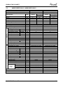
2.4
AWSI-FWDE024-N11
Model Indoor Unit
Model Outdoor Unit
Installation Method of Pipe
AWSI-FWDE024-N11
AWAU-YBDE024-H11
Flared
Units
Capacity (1)
Pdesign
SEER /SCOP (2)
Energy efficiency class
Annual energy consumption
Tbiv
Tol
Power supply
Circuit breaker rating
Fan type & quantity
Fan speeds
H/M/L
Air flow (3)
H/M/L
External static pressure
Min-Max
Sound power level (4)
H/M/L
(5)
Sound pressure level
H/M/L
Moisture removal
Condensate drain tube I.D
Dimensions
WxHxD
Weight
Package dimensions
LxWxH
Packaged weight
Stacking height
Refrigerant control
Compressor type, model
Fan type & quantity
Fan speeds
H/L
Air flow
H/L
Sound power level(4)
H/L
Sound pressure level(5)
H/L
Dimensions
WxHxD
Weight
Package dimensions
LxWxH
Packaged weight
Stacking height
Refrigerant type
Refrigerant charge (standard
connecting
tubing per
length)
Additional charge
1 meter
kW
kW
W/W
OUTDOOR
INDOOR
Characteristics
Liquid line
Suction line
Max.tubing length
Max.height difference
Operation control type
Heating elements
Others
Connections
between
units
2-4
kWh
oC
oC
V/Ph/H
z
A
RPM
m3/hr
Pa
dB(A)
dB(A)
l/hr
mm
mm
kg
mm
kg
units
RPM
m3/hr
dB(A)
dB(A)
mm
kg
mm
kg
units
kg(5m)
gr / 1m
In.(mm)
In.(mm)
m.
m.
Cooling
Heating
Average
N/A
N/A
N/A
N/A
N/A
N/A
N/A
6,8 (1,5-7,6)
6.8
5.1
A
467
N/A
N/A
220-240V/Single/50Hz
25
Centrifugal x 2
1300/1200/1050
1020/950/800
0
66
54/51/46
2.5
16
1200x630x190
32
1300x726x273
36
7
EEV
Twin-rotary DC Inverter
Axial x 1
850
3600
69
59
950x864x340
65.5
1140x510x930
73
2
R410A
2.3
7.5m<Length≤20m:+0g;20m<Length≤30m:+300g
3/8" (9.53)
5/8"(15.88)
30
15
Remote control
kW
SM FWDE/SXE 1-A.1 GB
RATING CONDITIONS
3.
RATING CONDITIONS
Rating conditions in accordance with ISO 5151 and ISO 13253 (for ducted units).
Cooling:
Indoor:
27oC DB 19oC WB
Outdoor: 35 oC DB
Heating:
Indoor:
20oC DB
Outdoor: 7oC DB 6oC WB
3.1
Operating Limits
FWDE series
Cooling
Voltage
Upper limit
Lower limit
1PH
Indoor
Outdoor
o
o
26 C DB 19 C WB 46 C DB
12oC DB 9oC WB -10oC DB
198 – 264 V
Upper limit
Lower limit
Upper limit
Lower limit
1PH
Indoor
Outdoor
o
o
26 C DB 19 C WB 46 C DB
21oC DB 15oC WB -10oC DB
27oC DB
24oC DB 18oC WB
-15oC DB -16oC WB
10oC DB
198 – 264 V
o
SXE series
Cooling
Heating
Voltage
SM FWDE/SXE 1-A.1 GB
o
3-1
OUTLINE DIMENSIONS
4.
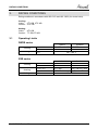
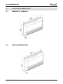
OUTLINE DIMENSIONS
4.1
SXE009/012, FWDE012
4.2
SXE018, FWDE018/024
SM FWDE/SXE 1-A.1 GB
4-1
OUTLINE DIMENSIONS
4.3
Outdoor Unit: YBDE009/012 / 018
4.4
Outdoor Unit: YBDE 024
4-2
SM FWDE/SXE 1-A.1 GB
ELECTRICAL DATA
5.
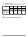
ELECTRICAL DATA
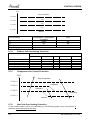
5.1
Single Phase Units
MODEL
SXE009
Power Supply
Max Current, A
Inrush Current A
Starting Current A
Circuit Breaker A
Power Supply Wiring
No. X Cross Section mm2
Interconnecting Cable
No. X Cross Section mm2
10
35
10.5
16
FWDE012
FWDE018
SXE012
SXE018
To indoor
1PH-230V-50Hz
10
12
35
35
10.5
10.5
16
20
FWDE024
To outdoor
14
45
10.5
20
3x1.5 mm2
3x1.5 mm2
3x2.5 mm2
3x2.5 mm2
4x1.5 mm2
4x1.5 mm2
4x2.5 mm2
4x1.5 mm2
NOTE
Power wiring cord should comply with local lows and electrical regulations
requirements.
SM FWDE/SXE 1-A.1 GB
5-1
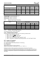
WIRING DIAGRAMS
6.
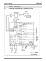
WIRING DIAGRAMS
6.1
Indoor Unit: SXE009/012/018, FWDE012/018/024
6-4
SM FWDE/SXE 1-A.1 GB
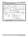
WIRING DIAGRAMS
6.2
6-2
Outdoor Unit: YBDE009/012/018
SM FWDE/SXE 1-A.1 GB
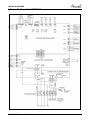
WIRING DIAGRAMS
6.3
Outdoor Unit: YBDE024
SM FWDE/SXE 1-A.1 GB
6-3
REFRIGERATION DIAGRAMS
7.
REFRIGERATION DIAGRAMS
7.1
Cooling Mode
7.2
Heating Mode
SM FWDE/SXE 1-A.1 GB
7-1
CONTROL SYSTEM
8.
CONTROL SYSTEM
8.1
Electronic Control
8.1.1
General Functions and Operating Rules (for single split models)
The DCI software is fully parametric.
All the model dependent parameters are shown in Blue color and with Italic style [parameter].
The parameters values are given in the last section of this control logic chapter of the service
manual.
8.1.2
System Operation Concept
The control function is divided between indoor and outdoor unit controllers. Indoor unit is the
system ‘Master’, requesting the outdoor unit for cooling/heating capacity supply. The outdoor unit is
the system ‘Slave’ and it must supply the required capacity unless it enters into a protection mode
avoiding it from supplying the requested capacity.
The capacity request is transferred via indoor to outdoor communication, and is
represented by a parameter called ‘NLOAD’. NLOAD is an integer number with
values between 0 and 127, and it represents the heat or cool load felt by the indoor
unit.
8.1.3
Compressor Frequency Control
8.1.3.1 NLOAD setting
The NLOAD setting is done by the indoor unit controller, based on a PI control scheme.
The actual NLOAD to be sent to the outdoor unit controller is based on the preliminary LOAD
calculation, the indoor fan speed, and the power shedding function.
NLOAD limits as a function of indoor fan speed:
Indoor Fan Speed Maximum NLOAD Cooling
Low
Max NLOADIF1C
Medium
Max NLOADIF2C
High
Max NLOADIF3C
Turbo
Max NLOADIF4C
Auto
Max NLOADIF5C
Maximum NLOAD Heating
127
127
127
127
127
8.1.3.2 Target Frequency Setting
The compressor target frequency is set by the following table, according to the NLOAD number
received from the indoor unit.
NLOAD
0
0 < NLOAD ≤ MinFreq
>MinFreq
Target Frequency [Hz]
0
MinFreq
MaxFreq MinFreq
{min (NLOAD, LoadDeadZo ne) MinFreq} MinFreq
LoadDeadZo ne MinFreq
Definitions
Cool
Heat
MinFreqC
MinFreqH
MinFreq
MaxFreqC
MaxFreqH
MaxFreq
LoadDeadZoneC
LoadDeadZoneH
LoadDeadZone
During running time (unlike starting) Compressor can operate only in its allowed
frequency range.
SM FWDE/SXE 1-A.1 GB
8-1
CONTROL SYSTEM
The lower allowed frequency is extracted from the following:
Mode
MinFreq
MinFreqA
HP
HPA
Cool
MinFreq
C
MinFreq
CA
HPAtMin
FreqC
HPAtMin
FreqCA
Heat
MinFreq
H
MinFreq
HA
HPAtMin
FreqH
HPAtMin
FreqHA
MinFreq
MinFreqA
Used only for ODU
NLOAD Calculation
MinFreq
HP
HPA
Pressure
Notes:
1. HP stands for High Pressure.
2. Pressure is represented by the following:
Cooling: max {OMT, OCT} in cooling mode,
Heating (Multi split): maximum ICT among all active and available inactive IDUs in heating
mode.
Heating (Single Split): ICT
3. The above parameters are determined from the compressor specifications.
The higher allowed frequency is extracted from the following:
Mode
‘Unit Night Mode’
Maximum Frequency (MaxFreq)
On
MaxFreqC*0.75
Off
MaxFreqC
On
MaxFreqH*0.75
Off
MaxFreqH
Cool
Heat
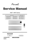
8.1.3.3 Frequency Changes Control
Frequency change rate is 1 Hz/sec.
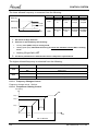
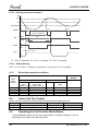
8.1.3.4 Compressor Starting Control
Frequency
Step 3
Step 2
Step 1
1
Minute
1
Minute
Time
Min 10 Minutes
8-2
SM FWDE/SXE 1-A.1 GB
WIRING DIAGRAMS
8.1.3.5 Minimum On and Off Time
3 minutes.
8.1.4
Indoor Fan Control
10 Indoor fan speeds are determined for each model. 5 speeds for cool/dry/fan modes and 5
speeds for heat mode.
When user sets the indoor fan speed to a fixed speed (Low/ Medium/ High), unit will operate
constantly at set speed.
When Auto Fan is selected, indoor unit controller can operate in all speeds. The actual speed is set
according to the cool/heat load.
8.1.4.1 Turbo Speed
The Turbo speed is activated during the first 30 minutes of unit operation when auto fan speed is
selected and under the following conditions:
Difference between set point and actual room temperature is bigger then 3 degrees.
Room temperature > 22 for cooling, or < 25 for heating.
8.1.5
Heating Element Control
Heating element can be started if LOAD > 0.8 * MaximumNLOAD AND Indoor Coil temperature <
45.
The heating element will be stopped when LOAD < 0.5 * MaximumNLOAD OR if Indoor Coil
temperature > 50.
8.1.6
Outdoor Fan Control
8.1.6.1 OFAN Operation
With keeping the OFAN general rules above in the highest priority, the operation of the OFAN will
be operating as the following:
Cooling
heating
Default Selection
Default Selection
Relay On; Triac Off
Relay On; Triac Off
Relay Off; Triac On
Relay Off; Triac On
Minimum
Condensing pressure
8.1.7
20
(27-7)
24
(20+4)
OAT
Note: OAT faulty, use Relay
Maximum
Evaporating pressure
22
(15+7)
26
(20+4)
OAT
Note: OAT faulty, use High Speed
The Triac and the Relay can never be activated at the same time
EEV (electronic Expansion valve) Control
EEV opening is defined as EEV = EEVOL + EEVCV
EEVOL is the initial EEV opening as a function of the compressor frequency, operation
mode, unit model and capacity.
EEVCV is a correction value for the EEV opening that is based on the Target CTT and
discharge superhea.
During the first 5 minutes of compressor operation EEVCV = 0.
Once the first 5 minutes are over, the correction value is calculated as follow: EEVCV =
EEVSH Discharge + EEVTarget CTT
EEVSH Discharge
For cooling, SHDischargeC = CTT- OMT
For Heating, SHDischargeH= CTT- ICT
SM FWDE/SXE 1-A.1 GB
8-3
CONTROL SYSTEM
EEVTarget CTT
For cooling, Target CTT = Target_CTT_Alpha_C *OMT
- Target_CTT_Beta_C *ICT
+Target_CTT_Gamma_C *Actual Compressor Frequency
+Target_CTT_Delta_C
For Heating, Target CTT = Target_CTT_Alpha_H*ICT
- Target_CTT_Beta_H*OCT
+Target_CTT_Gamma_H*Actual Compressor Frequency
+Target_CTT_Delta_H
8.1.8
Reversing Valve (RV) Control
Reversing valve is on in heat mode.
Switching of RV state is done only after compressor is off for over 3 minutes.
8.2
Fan Mode
In high/ medium/ low indoor fan user setting, unit will operate fan in selected speed.
In AutoFan user setting, fan speed will be adjusted automatically according to the difference
between actual room temperature and user set point temperature.
8.3
Cool Mode
NLOAD is calculated according to the difference between actual room temperature and user set
point temperature by PI control.
In high/ medium/ low indoor fan user setting, unit will operate fan in selected speed.
In AutoFan user setting, fan speed will be adjusted automatically according to the calculated
NLOAD.
8.4
Heat Mode
NLOAD is calculated according to the difference between actual room temperature and user set
point temperature by PI control.
In high/ medium/ low indoor fan user setting, unit will operate fan in selected speed.
In AutoFan user setting, fan speed will be adjusted automatically according to the calculated
NLOAD.
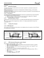
8.4.1
Temperature Compensation
4 degrees are reduced from room temperature reading (except when in I-Feel mode), to
compensate for temperature difference between high and low areas in the heated room, and for
coil heat radiation on room thermistor.
8.4.2
Indoor Fan Control in Heat Mode
Indoor fan speed depends on the indoor coil temperature:
ICTST ICTVL
8.5
ICTL
ICTH
ICTT
Auto Cool/Heat Mode
When in auto cool heat mode unit will automatically select between cool and heat mode according
to the difference between actual room temperature and user set point temperature (ΔT).
Unit will switch from cool to heat when compressor is off for 3 minutes, and ΔT < -3.
8-4
SM FWDE/SXE 1-A.1 GB
WIRING DIAGRAMS
Unit will switch from heat to cool when compressor is off for 5 minutes, and ΔT < -3.
8.6
Dry Mode
As long as room temperature is higher then the set point, indoor fan will work in low speed and
compressor will work between 0 and MaxNLOADIF1C Hz.
When the room temperature is lower than the set point, compressor will be switched OFF and
indoor fan will cycle 3 minutes OFF, 1 minute ON.
8.7
Protections
There are 5 protection codes.
Normal (Norm) – unit operate normally.
Stop Rise (SR) – compressor frequency can not be raised but does not have to be decreased.
HzDown1 (D1) – Compressor frequency is reduced by Down1 Hz/min.
HzDown2 (D2) – Compressor frequency is reduced by Down2 Hz/min.
Stop Compressor (SC) – Compressor is stopped.
8.7.1
Indoor Coil Defrost Protection
ICT
ICT < -2
-2 ≤ ICT < 0
0 ≤ ICT < 2
2 ≤ ICT < 4
4 ≤ ICT < 6
6 ≤ ICT < 8
8 ≤ ICT
8.7.2
Fast
Increasing
Increasing
ICT Trend
No change
Decreasing
Fast
Decreasing
SC
D1
SR
SR
Norm
Norm
SC
D1
SR
SR
Norm
Norm
SC
D2
D1
SR
SR
Norm
SC
D2
D2
D1
SR
SR
SC
D2
D2
D2
D1
SR
Normal
Indoor Coil over Heating Protection
ICT
ICT > 55
53 < ICT ≤ 55
49 < ICT ≤ 53
47 < ICT ≤ 49
45 < ICT ≤ 47
43 < ICT ≤ 45
ICT ≤ 43
8.7.3
Fast
Decreasing
Decreasing
ICT Trend
No Change
SC
D1
SR
SR
Norm
Norm
SC
D1
SR
SR
Norm
Norm
SC
D2
D1
SR
SR
Norm
Increasing
Fast
Increasing
SC
D2
D2
D1
SR
SR
SC
D2
D2
D2
D1
SR
Normal
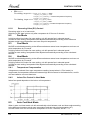
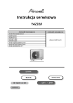
Compressor over Heating Protection
Compressor temperature can be in one of 5 control zones (4 in protection, and 1 normal),
according to the following chart.
SM FWDE/SXE 1-A.1 GB
8-5
CONTROL SYSTEM
CTT
Stop-Compresor
CTTOH4
P3
CTTOH3
P2
CTTOH2
P1
CTTOH1
Normal
Control Status
P1
P2
P3
Stop Compressor
8.7.4
Compressor Temperature
Increases
Norm
D1
D2
SR
SR
D1
SC
Outdoor Coil Overheating Protection
OMTn
OMTn ≥ HPC5
HPC4 ≤ OMTn < HPC5
HPC3 ≤ OMTn < HPC4
HPC2 ≤ OMTn < HPC3
HPC1≤ OMTn < HPC2
OMTn < HPC1
8.7.5
Else
OMTn-OMTn-1
<-1
-1
SC
D2
D1
SR
Norm
SC
D2
D1
SR
Norm
0
SC
D2
D1
SR
Norm
Norm
1
>1
SC
D2
D1
SR
Norm
SC
D2
D1
SR
Norm
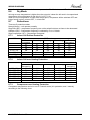
Compressor over Current Protection
CCR
Stop-Compresor
CCROC4
HzDown2
CCROC3
HzDown1
CCROC2
Stop-Rise
CCROC1
Normal
8.7.6
Heat Sink Over Heating Protection
A new control status will be set according to the following graph every one-minute or
whenever when going up by the rows.
8-6
SM FWDE/SXE 1-A.1 GB
WIRING DIAGRAMS
HSTn is the current reading of HST and HSTn-1 is the last reading of HST.
HSTn-HSTn-1
HSTn
<-1
-1
0
1
>1
HSTn > HSTOH5
SC
SC
SC
SC
SC
HSTOH4 ≤ HSTn < HSTOH5
D1
D1
D2
D2
D2
HSTOH3 ≤ HSTn < HSTOH4
SR
SR
D1
D2
D2
HSTOH2 ≤ HSTn < HSTOH3
SR
SR
SR
D1
D1
HSTOH1 ≤ HSTn < HSTOH2
Norm
Norm
Norm
SR
SR
HSTn < HSTOH1
Norm
(*) Normal (Norm) – No protection status is ON.
Stop-Rise (SR) – System is in protection.
HzDown1 (D1) - System is in protection.
HzDown2 (D2) - System is in protection.
8.7.7
System Over Power Protection
Powern-Powern-1
Powern
Powern > OVRPWR5
OVRPWR4 ≤ Powern < OVRPWR5
OVRPWR3 ≤ Powern < OVRPWR4
OVRPWR2 ≤ Powern < OVRPWR3
OVRPWR1 ≤ Powern < OVRPWR2
Powern < OVRPWR1
8.7.8
<-50
[-50,-1]
0
[1,50]
>50
SC
D1
SR
SR
Norm
SC
D1
SR
SR
Norm
SC
D2
D1
SR
Norm
Norm
SC
D2
D2
D1
SR
SC
D2
D2
D1
SR
Outdoor Coil Deicing Protection
In the deicing protection, IFAN is forced OFF.
8.7.8.1 Deicing Starting Conditions
Deicing operation will start when either one of the following conditions exist:
Case 1: OCT<–DST AND TLD > DI
Case 2: OCT<-4 AND TLD>100 minutes
Case 3: OCT is Invalid AND TLD > DI
Case 4: Unit is just switched to STBY AND OCT<-DST
Case 5: compressor is stopped during heating operation, OCT<-DST AND TLD>DI,
OCT – Outdoor Coil Temperature
OAT – Outdoor Air Temperature
TLD – Time from Last Deicing
DI – Deicing Interval (Time Interval Between Two Deicing)
DT- Deicing Time
DST is defined as:
When OAT>0 or OAT is invalid; then DST=8
When OAT≤0; then DST= round down (-DeicerCoef * OAT) + 8
Deicing interval time when compressor is first started in heat mode is 30 minutes.
Deicing interval time is changed (increased/ decreased in 10 minutes steps) as a function of
deicing time. If deicing time is shorter than former deicing time, the deicing interval time will be
increased. If deicing time is longer than former deicing time, the deicing interval time will be
decreased.
SM FWDE/SXE 1-A.1 GB
8-7
CONTROL SYSTEM
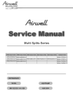
8.7.8.2 Deicing Protection Procedure
OCT
12
0
Threshold
COMP
ON
T1
T1
T2
max. 12 minutes
RV
DT
HEAT
T3
COOL
OFAN
T3
ON
OFF
EEVDeicerOpen
EEV
Any
T1 = DEICT1 seconds, T2 = DEICT2 seconds, T3 = DEICT3 seconds
8.7.8.3 Exiting Deicing
OCT > OCTExitDeicer or Deicer current time is over MaxDeicerTime minutes.
8.7.9
Exceeding operation conditions
Exceeding limits state
Indoor
Mode
request
Cooling
Cooling
Heating
Heating
8.8
Outdoor conditions
Indoor
Hydro
(Family 31)
A=47
B=-11
B=-18
A=+40
Indoor
Non Hydro
(Family is not 31)
A=47
B=-11
B=-18
A=+30
EnableExceedCond
1
0 (or OAT
faulty)
Idle
Idle
Idle
Idle
Cooling
Cooling
Heating
Heating
Normal state
(default)
Outdoor mode
Cool
Cool
Heat
Heat
Indoor Unit Dry Contact
Indoor unit Dry contact has two alternative functions that are selected by J8.
Function
Contact = Open
Contact = Short
J8 = Open
Presence Detector Connection No Limit
Forced to STBY
J8 = Short
Power Shedding Function
No Limit
Limit NLOAD
8.9
Operating the Unit from the Mode Button
Forced operation allows to start, stop and operate in Cooling or Heating, in pre-set
temperature according to the following table:
8-8
SM FWDE/SXE 1-A.1 GB
WIRING DIAGRAMS
Forced operation Mode
Pre-set Temperature
Cooling
200C
Heating
280C
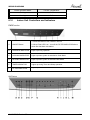
8.10
Indoor Unit Controllers and Indicators
FWDE series
1- Press the button to turn ON/OFF the unit.
A
ON/OFF Button
2- When Filter LED is on - turn off the FILTER INDICATOR after a
clean filter has been reinstalled.
B
OPERATE INDICATOR
Lights up during operation
C
COOLING INDICATOR
Lights up when system is switched to Cool Mode
D
HEATING INDICATOR
Lights up when system is switched Heat Mode
E
TIMER INDICATOR
Lights up during Timer and Sleep operation.
F
FILTER INDICATOR
Lights up when Air Filter needs to be cleaned.
SXE Series
SM FWDE/SXE 1-A.1 GB
8-9
CONTROL SYSTEM
A
HEATING INDICATOR
Lights up when system is switched Heat Mode
B
COOLING INDICATOR
Lights up when system is switched to Cool Mode
C
FAN MODE INDICATOR
Lights up in Fan Mode
D
OPERATE INDICATOR
Lights up during operation
TIMER INDICATOR
Lights up during Timer and Sleep operation.
F
FILTER INDICATOR
Lights up when Air Filter needs to be cleaned.
G
TEMP. SETTING INDICATORS
Each one of the seven indicators indicates the
following SPT: 18, 20, 22, 24, 26, 28, 30 [oc]. The odd
number temperatures are indicated by turning on the
two adjacent indicators.
H- Lights up when IFAN setting is High.
M- Lights up when IFAN setting is Medium.
L- Lights up when IFAN setting is Low.
A- Lights up when IFAN setting is Auto.
For short pressing:
When Filter LED is on - turn off the FILTER
INDICATOR after a clean filter has been reinstalled.
When Filter LED is off – enable/disable the buzzer
announcer, if selected.
In long pressing system enters set up mode (if in SB).
Toggle the unit between OPER & STBY modes.
Every short pressing , the next operation mode is
selected, in this order : SB → Cool Mode → Heat
Mode → SB → …
In long pressing system enters diagnostic mode.
Press this button to change the speed of the IFAN.
Each pressing change the speed in the sequence of:
..... L → M → H → Auto → L → ...
Pressing this button increases the SPT by 1oc.
Note: The Max SPT is 30oc.
Pressing this button decreases the SPT by 1oc.
Note: The Min SPT is 18oc.
E
H
I
J
K
Buttons
FAN SPEED INDICATORS
RESET / FILTERBUTTON
POWER BUTTON
Mode button
FAN speed button
TEMP. SETTING UP BUTTON
TEMP. SETTING DOWN
BUTTON
Note:
1. Pressing time is defined as the time between press and release.
2. If pressing time is one second or less – press is consider as short pressing.
3. If pressing time is three seconds or longer – pressing is considered as long pressing. In
between, pressing is undetermined and system will not respond to pressing.
8-10
SM FWDE/SXE 1-A.1 GB
WIRING DIAGRAMS
System Diagnostics from IDU
Pressing Mode button for long pressing in any operation mode, will activate diagnostic mode by the
acknowledgment of 3 short beeps and lighting of COOL and HEAT LED’s. Then, every short
pressing Mode button will scroll between indoor and outdoor unit diagnostic modes by the
acknowledgment of 3 short beeps and lighting of COOL and HEAT LED’s.
In diagnostic mode, system problems / information will be indicated by blinking of Heat & Cool
LED’s.
The coding method will be as follows:
Heat led will blink 5 times in 5 seconds, and then will be shut off for the next 5 seconds. Cool Led
will blink during the same 5 seconds according to the following IDU/ODU tables:
For IDU diagnostics:
No
1
2
3
4
5
6
7
8
9
10
11
…
17
18
19
20
21
22
24
25
26
27
28
29
30
31
Problem
AO
5
4
3
2
1
ICT is disconnected
ICT is shorted
RAT is disconnected
RAT is shorted
Reserved (for MSMP used as RGT fault)
ICTE shorted/disconnected (when enabled)
Undefined IDU Family/Model
No Communication
No Encoder
Reserved
Outdoor Unit Fault
Reserved
Yes
Yes
Yes
Yes
No
Yes
Yes
Yes
No
No
No
No
0
0
0
0
0
0
0
0
0
0
0
0
0
0
0
0
0
0
1
1
1
1
0
0
0
1
1
1
1
0
0
0
0
0
1
1
0
0
1
1
0
0
1
1
1
0
1
0
1
0
1
0
1
0
1
Defrost protection
Deicing Protection
Outdoor Unit Protection
Indoor Coil HP Protection
Overflow Protection
Reserved
EEPROM Not Updated
No
No
No
No
Yes
No
No
1
1
1
1
1
0
0
0
0
0
0
0
0
1
1
0
1
1
0
0
1
0
1
0
1
1
1
0
0
0
Bad EEPROM
Bad Communication
Using EEPROM data
Model A
Model B
Model C
Model D
No
No
No
No
No
No
No
1
1
1
1
1
1
1
1
1
1
1
1
1
1
0
0
0
1
1
1
1
0
1
1
0
0
1
1
1
0
1
0
1
0
1
SM FWDE/SXE 1-A.1 GB
8-11
CONTROL SYSTEM
8.11
Outdoor Unit Controllers and Indicators
8.11.1 The user display uses three 7 segments.
8.11.1.1 The user interface concept is Tree menus.
8.11.1.2 The navigation through the menu can be performed by either the key pad
or RC8 remote controller (through infra red receiver).
Command
Function
Keypad
Remote
Type
RC8 sketch:
controller
Scrolling among
Up or Down
options (up and
command
down).
Go down one level
Selection
in the menu or
command
select an option.
Up: Set Point ‘+’
Up or Down
Down: Set Point ‘-
key button.
LCD
‘
Select
FAN mode
button
Oper
Escaping
Go up one level in
Escape
command
the menu
button
Oper/STBY
SPT-
SPT+
FAN
Button Box
Note: the buttons above are selected according to RC8 design (refer to RC8 specifications) for the technician
convenient use.
1. The navigation type selection, remote controller or keypad, is set through software
parameter: HMIType=0 (keypad), HMIType=1 (remote controller)
2. The following table summarizes the remote controller commands:
Command
Type
Pressed
Button
SPT
Oper
Up
Down
‘+’
‘-‘
30
16
0
0
Escape
Enter
Reserved
Reserved
Oper
FAN
Sleep
Horizontal
Louver
I-FEEL
Other
Don’t care
Don’t care
Don’t care
Don’t care
1
0
0
0
Values on the IR protocol
Horizontal
FAN
Sleep
Louver
0
0
0
0
0
0
0
01
0
0
0
0
1
0
0
0
0
1
Reserved
Don’t care
0
0
0
0
20
0
0
0
0
Notes:
1. The zeros stated above must be checked in order to judge for proper message.
2.
I-FEEL
Other bits
0
0
0
0
0
0
0
0
0
0
0
0
1
0
0
0
Proper checksum has to be performed according to the RC7 specifications.
3. For any remote controller command, the most right ‘dot’ will blink for 1 second in order to
acknowledge the command is received.
8.11.1.3 Active selection or status will be indicated by blinking the display.
8.11.2 Keys functionality
o Scrolling will be done whenever the button is pressed.
8-12
SM FWDE/SXE 1-A.1 GB
WIRING DIAGRAMS
o When scrolling alpha values, if the scroll button is held in, the selection will change at the rate
of one step per second.
o The display will not roll over during selection (for example stop/Ode/Dia/Stp/Par/stop)
8.11.3 Menus
8.11.3.1 General
All the green colored items will be deactivated for single split units.
8.11.3.2
Main Menu
Technician Test (tt)
Installation Test (it)
Diagnostics (dia)
Set Up (Stp)
Status (Stt)
Notes:
1. The default presentation will be alternation among:
o
the mode of the unit (Cl/Ht/Sb) shown for 2 sec.
o
ID + the detected IDUs number shown for 2 sec.
o
Active fault (among ODU or IDUs), each to be shown for 2 sec.
2. In diagnostics menu:
o
xx means failure code.
o
Maximum 5 faults are presented for each unit (each IDUs/ODU). When no faults “-“ sign will be shown.
o
The active faults have higher priority for presentation than non active ones.
o
Non active faults are presented according to their chronological order, starting from
the latest one.
o
Whenever a new active fault occurs, it will be presented immediately.
o
Active faults are blinking, where non active ones do not.
3. Exiting ‘Status’ menu and its sub-menus back to the main menu is done by either pressing
escape or after continuous 60 minutes out of any press.
4. Technician Test mode, once is selected, it cannot last more than predefined time. Refer to
technician test for details, Sect. Error! Reference source not found..
5. All the menus, except Status and its sub-menu, Technician Test once selected, are
automatically exited to the main menu after 10 continuous minute out of any press.
6. When Technician test cool or heat menus are selected (operative), it will be blinking
constantly until, this menu is escaped.
7. When the installation test begins, the system will show up count down based (refer to the
installation test sect. Error! Reference source not found.. At the end of the installation
test, the result will be presented.
8. For the indoor diagnostics, whenever there is no-communication with indoor unit or indoor
unit is not detected, ‘no-communication’ will be shown under the relevant indoor unit
diagnostics. In addition to the indoor diagnostics, these faults will be also shown as well
under the default show.
9. When Alpha and numeric values are combined, they will be separated by dot.
SM FWDE/SXE 1-A.1 GB
8-13
CONTROL SYSTEM
10. For technician mode presentation, the active setting target compressor frequency will be
presented directly upon entry. The active selected value will be blinking. The set target
compressor frequency will be enabled to be scrolled up and down within the minimum and
maximum operating frequency values (the values do depend on the outdoor model setting
as well as the operation mode- cool or heat)
11. For technician mode presentation, whenever the system exit technician mode due any of
the faults listed under Sect. Error! Reference source not found., the HMI will show the
fault in the same way to Diagnostics sub menu.
Fault Code:
No
Problem
1
OCT is shorted/disconnected
2
CTT is shorted/disconnected
3
HST is shorted/disconnected
4
OAT is shorted/disconnected
5
OMT is shorted/disconnected
6
RGT is shorted/disconnected
7
RLT is shorted/disconnected
8
Reserved
9
Reserved
10
Reserved
11
Compressor IPM Fault / IPM Driver Pin / Compressor Current Sensor Fault
12
Bad EEPROM
13
DC under voltage
14
DC over voltage
15
AC under voltage/AC over Voltage/Zero Crossing detection
16
Mismatch between IDU & ODU models
17
No Communication
18
System Over Power
19
PFC Current sensor
20
Heat sink Over Heating
21
Deicing
22
Compressor Over Heating
23
Compressor Over Current
24
No OFAN Feedback
25
OFAN IPM fault / OFAN IPM Driver Pin
26
Compressor Lock
27
Bad Communication
Missing ODU configuration
28
29
Undefined ODU Model
30
Outdoor/Indoor Coil Overheating
31
Operation conditions are exceeded
8-14
SM FWDE/SXE 1-A.1 GB
EXPLODED VIEWS & SPARE PART LISTS
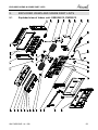
9.
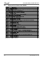
EXPLODED VIEWS AND SPARE PART LISTS
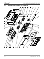
9.1
Exploded view of Indoor unit: SXE009/012, FWDE012
SM FWDE/SXE 1-A.1 GB
9-1
EXPLODED VIEWS & SPARE PART LISTS
9.2
9-2
Spare part list of Intdoor Unit: SXE009
SM FWDE/SXE 1-A.1 GB
EXPLODED VIEWS & SPARE PART LISTS
9.3
Spare part list of Intdoor Unit: SXE012
SM FWDE/SXE 1-A.1 GB
9-3
EXPLODED VIEWS & SPARE PART LISTS
9.4
9-4
Spare part list of Intdoor Unit: FWDE012
SM FWDE/SXE 1-A.1 GB
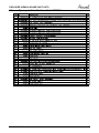
EXPLODED VIEWS & SPARE PART LISTS
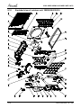
9.5
Exploded view of Indoor unit: SXE018, FWDE018
SM FWDE/SXE 1-A.1 GB
9-5
EXPLODED VIEWS & SPARE PART LISTS
9.6
9-6
Spare part list of Intdoor Unit: SXE018
SM FWDE/SXE 1-A.1 GB
EXPLODED VIEWS & SPARE PART LISTS
9.7
Spare part list of Intdoor Unit: FWDE018
SM FWDE/SXE 1-A.1 GB
9-7
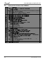
EXPLODED VIEWS & SPARE PART LISTS
9.8
9-8
Exploded view of Indoor unit: FWDE024
SM FWDE/SXE 1-A.1 GB
EXPLODED VIEWS & SPARE PART LISTS
9.9
Spare part list of Intdoor Unit: FWDE024
SM FWDE/SXE 1-A.1 GB
9-9
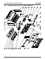
EXPLODED VIEWS & SPARE PART LISTS
9.10
9-10
Exploded view of outdoor unit: YBDE009/012/018
SM FWDE/SXE 1-A.1 GB
EXPLODED VIEWS & SPARE PART LISTS
9.11
Spare part list of Outdoor Unit: YBDE009/012
SM FWDE/SXE 1-A.1 GB
9-11
EXPLODED VIEWS & SPARE PART LISTS
9.12
9-12
Spare part list of Outdoor Unit: YBDE018
SM FWDE/SXE 1-A.1 GB
EXPLODED VIEWS & SPARE PART LISTS
9.13
Exploded view of outdoor unit: YBDE024
SM FWDE/SXE 1-A.1 GB
9-13
EXPLODED VIEWS & SPARE PART LISTS
9.14
9-14
Spare part list of Outdoor Unit: YBDE024
SM FWDE/SXE 1-A.1 GB