1
Summit 300-48 Switch
Software User Guide
Software Version 6.2a
Extreme Networks, Inc.
3585 Monroe Street
Santa Clara, California 95051
(888) 257-3000
http://www.extremenetworks.com
Published: May 2004
Part number: 123007-00 Rev. 02
Alpine, Altitude, BlackDiamond, EPICenter, Ethernet Everywhere, Extreme Ethernet Everywhere, Extreme Networks,
Extreme Turbodrive, Extreme Velocity, ExtremeWare, ExtremeWorks, GlobalPx Content Director, the Go Purple
Extreme Solution Partners Logo, ServiceWatch, Summit, the Summit7i Logo, and the Color Purple, among others, are
trademarks or registered trademarks of Extreme Networks, Inc. or its subsidiaries in the United States and other
countries. Other names and marks may be the property of their respective owners.
© 2004 Extreme Networks, Inc. All Rights Reserved. Specifications are subject to change without notice.
2
Contents
Preface
Chapter 1
Chapter 2
Introduction
17
Conventions
17
Related Publications
18
ExtremeWare Overview
Summary of Features
Unified Access
Virtual LANs (VLANs)
Spanning Tree Protocol
Quality of Service
Load Sharing
ESRP-Aware Switches
19
20
20
20
21
21
21
Software Licensing
21
Security Licensing
Obtaining a Security License
Security Features Under License Control
22
22
22
Software Factory Defaults
22
Accessing the Switch
Understanding the Command Syntax
Syntax Helper
Command Shortcuts
Summit 300-48 Switch Numerical Ranges
Names
Symbols
25
26
26
26
27
27
Line-Editing Keys
27
Command History
28
Common Commands
28
Summit 300-48 Switch Software User Guide
3
Contents
Chapter 3
4
Configuring Management Access
User Account
Administrator Account
Default Accounts
Creating a Management Account
30
31
31
31
32
Domain Name Service Client Services
33
Checking Basic Connectivity
Ping
Traceroute
34
34
34
Managing the Switch
Overview
37
Using the Console Interface
38
Using Telnet
Connecting to Another Host Using Telnet
Configuring Switch IP Parameters
Disconnecting a Telnet Session
Controlling Telnet Access
38
38
38
40
41
Using Secure Shell 2 (SSH2)
Enabling SSH2 for Inbound Switch Access
41
41
Using SNMP
Accessing Switch Agents
Supported MIBs
Configuring SNMP Settings
Displaying SNMP Settings
42
42
43
43
44
Authenticating Users
RADIUS Client
45
45
Using ExtremeWare Vista
Controlling Web Access
Setting Up Your Browser
Accessing ExtremeWare Vista
Navigating ExtremeWare Vista
Saving Changes
Filtering Information
Do a GET When Configuring a VLAN
Sending Screen Output to Extreme Networks
49
49
49
50
50
52
52
53
53
Using the Simple Network Time Protocol
Configuring and Using SNTP
SNTP Configuration Commands
SNTP Example
53
53
56
56
Show Odometer Command
56
Summit 300-48 Switch Software User Guide
Contents
Chapter 4
Chapter 5
Chapter 6
Configuring Ports on a Switch
Port Numbering
57
Enabling and Disabling Switch Ports
Configuring Switch Port Speed and Duplex Setting
Switch Port Commands
57
58
58
Load Sharing on the Switch
Load-Sharing Algorithms
Configuring Switch Load Sharing
Load-Sharing Example
Verifying the Load-Sharing Configuration
59
59
60
61
61
Switch Port-Mirroring
Port-Mirroring Commands
Port-Mirroring Example
61
62
63
Extreme Discovery Protocol
EDP Commands
63
63
Virtual LANs (VLANs)
Overview of Virtual LANs
Benefits
65
65
Types of VLANs
Port-Based VLANs
Tagged VLANs
66
66
68
VLAN Names
Default VLAN
Renaming a VLAN
71
71
72
Configuring VLANs on the Switch
VLAN Configuration Commands
VLAN Configuration Examples
72
72
73
Displaying VLAN Settings
73
Wireless Networking
Overview of Wireless Networking
Summary of Wireless Features
75
76
Wireless Devices
Altitude 300-2d Detachable Antenna
76
77
Bridging
77
Managing the Altitude 300
Wireless Show Commands
78
78
Configuring RF Properties
79
Configuring RF Monitoring
80
Summit 300-48 Switch Software User Guide
5
Contents
AP Detection
Chapter 7
6
81
Managing Wireless Clients
Performing Client Scanning
Collecting Client Information
83
83
85
Configuring Wireless Switch Properties
Configuring Country Codes
87
88
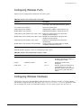
Configuring Wireless Ports
89
Configuring Wireless Interfaces
89
Force Disassociation
90
Event Logging and Reporting
91
Unified Access Security
Overview of Security
93
User Access Security
Authentication
Encryption
Cipher Suites
94
94
96
96
Network Login
Web-Based and 802.1x Authentication
Campus and ISP Modes
Interoperability Requirements
Exclusions and Limitations
Configuring Network Login
Web-Based Authentication User Login Using Campus Mode
DHCP Server on the Switch
Displaying DHCP Information
Additional Configuration Details
Network Login Configuration Commands
Displaying Network Login Settings
Wireless Network Login Considerations
96
97
99
99
100
100
103
104
104
104
105
106
107
MAC RADIUS
107
Network Security Policies for Wireless Interfaces
Policy Design
Policy Examples
Policies and RADIUS Support
RADIUS Attributes
107
107
109
109
109
CLI Commands for Security on the Switch
Security Profile Commands
111
111
Secure Web Login Access
Creating Certificates and Private Key
113
114
Example Wireless Configuration Processes
115
Summit 300-48 Switch Software User Guide
Contents
Wireless Management Configuration Example
Security Configuration Examples
Profile Assignment Example
Chapter 8
Chapter 9
Chapter 10
115
116
131
Power Over Ethernet
Overview
Summary of PoE Features
133
133
Port Power Management
Port Power Operator Limit
Power Budget Management
Port Power Events
Load Sharing Power Supplies
134
134
134
136
137
Per-Port LEDs
139
Configuring Power Over Ethernet
139
Forwarding Database (FDB)
Overview of the FDB
FDB Contents
FDB Entry Types
How FDB Entries Get Added
Associating a QoS Profile with an FDB Entry
143
143
143
144
144
Configuring FDB Entries
FDB Configuration Examples
145
146
Displaying FDB Entries
146
Access Policies
Overview of Access Policies
Access Control Lists
Rate Limits
147
147
147
Using Access Control Lists
Access Masks
Access Lists
Rate Limits
How Access Control Lists Work
Access Mask Precedence Numbers
Specifying a Default Rule
The permit-established Keyword
Adding Access Mask, Access List, and Rate Limit Entries
Deleting Access Mask, Access List, and Rate Limit Entries
Verifying Access Control List Configurations
Access Control List Commands
Access Control List Examples
147
148
148
149
149
150
150
151
151
152
152
152
156
Summit 300-48 Switch Software User Guide
7
Contents
Chapter 11
Chapter 12
Chapter 13
Quality of Service (QoS)
Overview of Policy-Based Quality of Service
161
Applications and Types of QoS
Voice Applications
Video Applications
Critical Database Applications
Web Browsing Applications
File Server Applications
162
162
162
162
163
163
Configuring QoS for a Port or VLAN
163
Traffic Groupings
Access List Based Traffic Groupings
MAC-Based Traffic Groupings
Explicit Class of Service (802.1p and DiffServ) Traffic Groupings
Configuring DiffServ
Physical and Logical Groupings
164
164
165
166
168
170
Verifying Configuration and Performance
QoS Monitor
Displaying QoS Profile Information
171
171
172
Modifying a QoS Configuration
172
Traffic Rate-Limiting
172
Status Monitoring and Statistics
Status Monitoring
173
Port Statistics
175
Port Errors
176
Port Monitoring Display Keys
177
Setting the System Recovery Level
177
Logging
Local Logging
Remote Logging
Logging Configuration Changes
Logging Commands
178
179
179
180
180
RMON
About RMON
RMON Features of the Switch
Configuring RMON
Event Actions
182
182
182
183
184
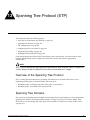
Spanning Tree Protocol (STP)
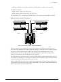
Overview of the Spanning Tree Protocol
8
185
Summit 300-48 Switch Software User Guide
Contents
Chapter 14
Appendix A
Spanning Tree Domains
Defaults
STPD BPDU Tunneling
185
186
186
STP Configurations
186
Configuring STP on the Switch
STP Configuration Example
188
191
Displaying STP Settings
191
Disabling and Resetting STP
192
IP Unicast Routing
Overview of IP Unicast Routing
Router Interfaces
Populating the Routing Table
193
194
194
Proxy ARP
ARP-Incapable Devices
Proxy ARP Between Subnets
196
196
196
Relative Route Priorities
197
Configuring IP Unicast Routing
Verifying the IP Unicast Routing Configuration
197
198
IP Commands
198
Routing Configuration Example
202
Displaying Router Settings
203
Resetting and Disabling Router Settings
203
Configuring DHCP/BOOTP Relay
Verifying the DHCP/BOOTP Relay Configuration
204
205
UDP-Forwarding
Configuring UDP-Forwarding
UDP-Forwarding Example
ICMP Packet Processing
UDP-Forwarding Commands
205
205
206
206
206
Safety Information
Important Safety Information
Power
Power Cord
Connections
Lithium Battery
Appendix B
209
209
210
210
211
Supported Standards
Summit 300-48 Switch Software User Guide
9
Contents
Appendix C
Appendix D
Software Upgrade and Boot Options
Downloading a New Image
Rebooting the Switch
215
216
Saving Configuration Changes
Returning to Factory Defaults
216
216
Using TFTP to Upload the Configuration
217
Using TFTP to Download the Configuration
Downloading a Complete Configuration
Downloading an Incremental Configuration
Scheduled Incremental Configuration Download
Remember to Save
218
218
218
218
219
Upgrading and Accessing BootROM
Upgrading Bootloader
Accessing the Bootstrap CLI
Accessing the Bootloader CLI
219
219
219
220
Boot Option Commands
221
Troubleshooting
LEDs
223
Using the Command-Line Interface
Port Configuration
VLANs
STP
224
225
226
227
Debug Tracing
Debug Trace for Wireless
227
227
TOP Command
228
Contacting Extreme Technical Support
228
Index
Index of Commands
10
Summit 300-48 Switch Software User Guide
Figures
1
2
3
4
5
6
7
8
9
10
11
12
13
14
15
16
17
18
Summit 300-48 Switch Software User Guide
Example of a port-based VLAN on the Summit 300-48 switch
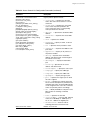
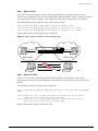
Single port-based VLAN spanning two switches
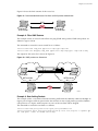
Two port-based VLANs spanning two switches
Physical diagram of tagged and untagged traffic
Logical diagram of tagged and untagged traffic
Sample integrated wired and wireless network
Permit-established access list example topology
Access control list denies all TCP and UDP traffic
Access list allows TCP traffic
Host A initiates a TCP session to host B
Permit-established access list filters out SYN packet to destination
ICMP packets are filtered out
Ethernet packet encapsulation
IP packet header encapsulation
Multiple Spanning Tree Domains
Tag-based STP configuration
Routing between VLANs
Unicast routing configuration example
66
67
68
70
70
76
156
157
158
158
159
159
166
168
187
188
194
202
11
Figures
12
Summit 300-48 Switch Software User Guide
Tables
1
2
3
4
5
6
7
8
9
10
11
12
13
14
15
16
17
18
19
20
21
22
23
24
25
26
27
28
29
30
31
32
33
Summit 300-48 Switch Software User Guide
Notice Icons
Text Conventions
ExtremeWare Summit 300-48 Factory Defaults
Command Syntax Symbols
Line-Editing Keys
Common Commands
Default Accounts
DNS Commands
Ping Command Parameters
SNMP Configuration Commands
RADIUS Commands
Multiselect List Box Key Definitions
Greenwich Mean Time Offsets
SNTP Configuration Commands
Switch Port Commands
Switch Port-Mirroring Configuration Commands
EDP Commands
VLAN Configuration Commands
Wireless Port Antenna Command
Wireless Port Bridging Command
Wireless Show Commands
RF Configuration Commands
RF Profile Property Values
AP Scan Configuration Commands
AP Scan Results (Alphabetized)
Client Configuration Commands
Client Scan Commands
Client Scan Performance Results Per Wireless Interface
Client Scan Results
Client Current State Commands
Client Current State Details
Client Debugging Commands
Client Diagnostic and History Information
17
18
22
27
27
28
31
33
34
43
45
51
54
56
58
62
63
72
77
77
78
79
80
81
82
83
83
84
84
85
85
86
86
13
Tables
34
35
36
37
38
39
40
41
42
43
44
45
46
47
48
49
50
51
52
53
54
55
56
57
58
59
60
61
62
63
64
65
66
67
68
69
70
71
72
73
74
75
76
77
78
79
14
Client Aging Configuration Command
Switch-Level Wireless Configuration Commands
Switch-Level Configuration Property Values
Country Code Command
Country Codes
Wireless Port Configuration Commands
Wireless Port Configuration Property Values
Wireless interface Configuration Commands
Force Disassociation Command
Security Options
Wi-Fi Security Cipher Suites
VSA Definitions for Web-based and 802.1x Network Login
Network Login Configuration Commands
Authentication-Based Network Access Example
RADIUS Request Attributes
Vendor-Specific Attributes
Security Profile Commands
Security Profile Command Property Values
Security Configuration Options
HTTP and HTTPS Access Commands
Commands to Create Certificates and Private Key
Operator Commands for Port Power Budgeting
Power supplies
Power Parameter Restrictions
Power Supply Mode Commands
Per-Port LEDs
Power Over Ethernet Configuration Commands
PoE Show Commands
FDB Configuration Commands
Access Control List Configuration Commands
Traffic Type and QoS Guidelines
QoS Configuration Commands
Traffic Groupings by Precedence
802.1p Priority Value-to-QoS Profile to Hardware Queue Default Mapping
802.1p Configuration Commands
DiffServ Configuration Commands
Default Code Point-to-QoS Profile Mapping
Status Monitoring Commands
Port Monitoring Display Keys
Fault Levels Assigned by the Switch
Fault Log Subsystems
Logging Commands
Event Actions
STP Configuration Commands
STP Disable and Reset Commands
Relative Route Priorities
87
87
87
88
88
89
89
90
90
94
96
99
105
109
109
110
111
111
112
113
114
136
137
138
138
139
139
141
145
153
163
163
164
167
167
168
169
174
177
178
178
180
184
189
192
197
Summit 300-48 Switch Software User Guide
Tables
80
81
82
83
84
85
86
87
88
Summit 300-48 Switch Software User Guide
Basic IP Commands
Route Table Configuration Commands
ICMP Configuration Commands
Router Show Commands
Router Reset and Disable Commands
UDP-Forwarding Commands
Bootstrap Command Options
Bootloader Command Options
Boot Option Commands
198
199
200
203
203
206
220
220
221
15
Tables
16
Summit 300-48 Switch Software User Guide
Preface
This preface provides an overview of this guide, describes guide conventions, and lists other
publications that may be useful.
Introduction
This guide provides the required information to install the Summit™ 300-48 switch and configure the
ExtremeWare™ software running on the Summit 300-48 switch.
This guide is intended for use by network administrators who are responsible for installing and setting
up network equipment. It assumes a basic working knowledge of:
• Local area networks (LANs)
• Ethernet concepts
• Ethernet switching and bridging concepts
• Routing concepts
• Internet Protocol (IP) concepts
• Simple Network Management Protocol (SNMP)
NOTE
If the information in the release notes shipped with your switch differs from the information in this guide,
follow the release notes.
Conventions
Table 1 and Table 2 list conventions that are used throughout this guide.
Table 1: Notice Icons
Icon
Notice Type
Alerts you to...
Note
Important features or instructions.
Summit 300-48 Switch Software User Guide
17
Preface
Table 1: Notice Icons (continued)
Icon
Notice Type
Alerts you to...
Caution
Risk of personal injury, system damage,
or loss of data.
Warning
Risk of severe personal injury.
Table 2: Text Conventions
Convention
Description
Screen displays
This typeface indicates command syntax, or represents information
as it appears on the screen.
The words “enter”
and “type”
When you see the word “enter” in this guide, you must type
something, and then press the Return or Enter key. Do not press the
Return or Enter key when an instruction simply says “type.”
[Key] names
Key names are written with brackets, such as [Return] or [Esc].
If you must press two or more keys simultaneously, the key names
are linked with a plus sign (+). Example:
Press [Ctrl]+[Alt]+[Del].
Words in italicized type
Italics emphasize a point or denote new terms at the place where
they are defined in the text.
Related Publications
The publications related to this one are:
• ExtremeWare Release Notes
• Summit 300-48 Switch Release Notes
Documentation for Extreme Networks products is available on the World Wide Web at the following
location:
• http://www.extremenetworks.com/
18
Summit 300-48 Switch Software User Guide
1
ExtremeWare Overview
This chapter describes the following topics:
• Summary of Features on page 19
• Security Licensing on page 22
• Software Factory Defaults on page 22
ExtremeWare is the full-featured software operating system that is designed to run on the
Summit 300-48 switch. This section describes the supported ExtremeWare features for the Summit
300-48 switch.
Summary of Features
The Summit 300-48 switch supports the following ExtremeWare features:
• Unified Access support
• Virtual local area networks (VLANs) including support for IEEE 802.1Q and IEEE 802.1p
• Spanning Tree Protocol (STP) (IEEE 802.1D)
• Quality of Service (QoS) including support for IEEE 802.1p, MAC QoS, and four hardware queues
• Wire-speed Internet Protocol (IP) forwarding
• Extreme Standby Router Protocol (ESRP) - Aware support
• Diffserv support
• Access-policy support for routing protocols
• Access list support for packet filtering
• Access list support for rate-limiting
• Load sharing on multiple ports
• RADIUS client
• Console command-line interface (CLI) connection
• Telnet CLI connection
Summit 300-48 Switch Software User Guide
19
ExtremeWare Overview
• SSH2 connection
• Simple Network Management Protocol (SNMP) support
• Remote Monitoring (RMON)
• Traffic mirroring for ports
Unified Access
The Summit 300-48 supports the Unified Access architecture, enabling wired and wireless applications
across a completely integrated enterprise infrastructure. With the Altitude product line, the Summit
300-48 supports 802.11 WLAN connectivity. Provisioning of Unified Access is completely controlled by
the Summit 300-48.
Virtual LANs (VLANs)
ExtremeWare has a VLAN feature that enables you to construct your broadcast domains without being
restricted by physical connections. A VLAN is a group of location- and topology-independent devices
that communicate as if they were on the same physical local area network (LAN).
Implementing VLANs on your network has the following three advantages:
• They help to control broadcast traffic. If a device in VLAN Marketing transmits a broadcast frame,
only VLAN Marketing devices receive the frame.
• They provide extra security. Devices in VLAN Marketing can only communicate with devices on
VLAN Sales using routing services.
• They ease the change and movement of devices on networks.
NOTE
For more information on VLANs, see Chapter 5, “Virtual LANs (VLANs)”.
Spanning Tree Protocol
The Summit 300-48 supports the IEEE 802.1D Spanning Tree Protocol (STP), which is a bridge-based
mechanism for providing fault tolerance on networks. STP enables you to implement parallel paths for
network traffic, and ensure that:
• Redundant paths are disabled when the main paths are operational.
• Redundant paths are enabled if the main traffic paths fail.
A single spanning tree can span multiple VLANs.
NOTE
For more information on STP, see Chapter 13, “Spanning Tree Protocol (STP)”.
20
Summit 300-48 Switch Software User Guide
Software Licensing
Quality of Service
ExtremeWare has Quality of Service (QoS) features that support IEEE 802.1p, MAC QoS, and four
queues. These features enable you to specify service levels for different traffic groups. By default, all
traffic is assigned the “normal” QoS policy profile. If needed, you can create other QoS policies and
rate-limiting access control lists and apply them to different traffic types so that they have different
maximum bandwidth, and priority.
NOTE
For more information on Quality of Service, see Chapter 11, “Quality of Service (QoS)”.
Load Sharing
Load sharing allows you to increase bandwidth and resiliency by using a group of ports to carry traffic
in parallel between systems. The sharing algorithm allows the switch to use multiple ports as a single
logical port. For example, VLANs see the load-sharing group as a single virtual port. The algorithm also
guarantees packet sequencing between clients.
NOTE
For information on load sharing, see Chapter 4, “Configuring Ports on a Switch”.
ESRP-Aware Switches
Extreme switches that are not running ESRP, but are connected on a network that has other Extreme
switches running ESRP are ESRP-aware. When ESRP-aware switches are attached to ESRP-enabled
switches, the ESRP-aware switches reliably perform fail-over and fail-back scenarios in the prescribed
recovery times. No configuration of this feature is necessary.
If Extreme switches running ESRP are connected to layer 2 switches that are not manufactured by
Extreme Networks (or Extreme switches that are not running ExtremeWare 4.0 or above), the fail-over
times seen for traffic local to the segment may appear longer, depending on the application involved
and the FDB timer used by the other vendor’s layer 2 switch. As such, ESRP can be used with layer 2
switches from other vendors, but the recovery times vary.
The VLANs associated with the ports connecting an ESRP-aware switch to an ESRP-enabled switch
must be configured using an 802.1Q tag on the connecting port, or, if only a single VLAN is involved, as
untagged using the protocol filter any. ESRP will not function correctly if the ESRP-aware switch
interconnection port is configured for a protocol-sensitive VLAN using untagged traffic.
Software Licensing
Summit 300-48 switches support Advanced Edge licensing.
Summit 300-48 Switch Software User Guide
21
ExtremeWare Overview
Security Licensing
Certain additional ExtremeWare security features, such as the use of Secure Shell (SSH2) encryption,
may be under United States export restriction control. Extreme Networks ships these security features in
a disabled state. You can obtain information on enabling these features at no charge from Extreme
Networks.
Obtaining a Security License
To obtain information on enabling features that require export restriction, access the Extreme Networks
Support website at:
http://www.extremenetworks.com/go/security.htm
Fill out a contact form to indicate compliance or noncompliance with the export restrictions. If you are
in compliance, you will be given information that will allow you to enable security features.
Security Features Under License Control
ExtremeWare version 6.0 and above supports the SSH2 protocol. SSH2 allows the encryption of session
data. The encryption methods used are under U.S. export restriction control.
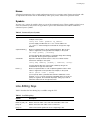
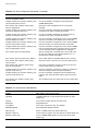
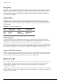
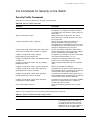
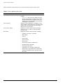
Software Factory Defaults
Table 3 shows factory defaults for Summit 300-48 ExtremeWare features.
Table 3: ExtremeWare Summit 300-48 Factory Defaults
Item
Default Setting
Serial or Telnet user account
admin with no password and user with no password
Telnet
Enabled
SSH2
Disabled
SNMP
Enabled
SNMP read community string
public
SNMP write community string
private
RMON
Disabled
BOOTP
Disabled on the default VLAN (default)
QoS
All traffic is part of the default queue
802.1p priority
Recognition enabled
802.3x flow control
Enabled on Gigabit Ethernet ports
Virtual LANs
Two VLANs predefined. VLAN named default contains all
ports and belongs to the STPD named s0.
802.1Q tagging
All packets are untagged on the default VLAN (default).
Spanning Tree Protocol
Disabled for the switch; enabled for each port in the STPD.
Forwarding database aging period
300 seconds (5 minutes)
IP Routing
Disabled
22
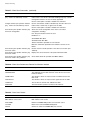
Summit 300-48 Switch Software User Guide
Software Factory Defaults
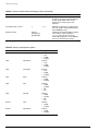
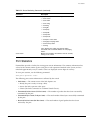
Table 3: ExtremeWare Summit 300-48 Factory Defaults (continued)
Item
Default Setting
IP multicast routing
Disabled
IGMP
Enabled
IGMP snooping
Disabled
SNTP
Disabled
DNS
Disabled
Port Mirroring
Disabled
Wireless
Enabled
NOTE
For default settings of individual ExtremeWare features, see the applicable individual chapters in this
guide.
Summit 300-48 Switch Software User Guide
23
ExtremeWare Overview
24
Summit 300-48 Switch Software User Guide
2
Accessing the Switch
This chapter describes the following topics:
• Understanding the Command Syntax on page 25
• Line-Editing Keys on page 27
• Command History on page 28
• Common Commands on page 28
• Configuring Management Access on page 30
• Domain Name Service Client Services on page 33
• Checking Basic Connectivity on page 34
Understanding the Command Syntax
This section describes the steps to take when entering a command. Refer to the sections that follow for
detailed information on using the command-line interface (CLI).
When entering a command at the prompt, ensure that you have the appropriate privilege level. Most
configuration commands require you to have the administrator privilege level. To use the CLI, follow
these steps:
1 Enter the command name.
If the command does not include a parameter or values, skip to step 3. If the command requires
more information, continue to step 2.
2 If the command includes a parameter, enter the parameter name and values.
3 The value part of the command specifies how you want the parameter to be set. Values include
numerics, strings, or addresses, depending on the parameter.
4 After entering the complete command, press [Return].
NOTE
If an asterisk (*) appears in front of the command-line prompt, it indicates that you have outstanding
configuration changes that have not been saved. For more information on saving configuration changes,
see Appendix C, “Software Upgrade and Boot Options”.
Summit 300-48 Switch Software User Guide
25
Accessing the Switch
Syntax Helper
The CLI has a built-in syntax helper. If you are unsure of the complete syntax for a particular command,
enter as much of the command as possible and press [Return]. The syntax helper provides a list of
options for the remainder of the command.
The syntax helper also provides assistance if you have entered an incorrect command.
Command Completion with Syntax Helper
ExtremeWare provides command completion by way of the [Tab] key. If you enter a partial command,
pressing the [Tab] key posts a list of available options, and places the cursor at the end of the command.
Abbreviated Syntax
Abbreviated syntax is the most unambiguous, shortest allowable abbreviation of a command or
parameter. Typically, this is the first three letters of the command.
In command tables throughout this guide, abbreviated syntax is noted using bold characters.
NOTE
When using abbreviated syntax, you must enter enough characters to make the command
unambiguous and distinguishable to the switch.
Command Shortcuts
All named components of the switch configuration must have a unique name. Components are named
using the create command. When you enter a command to configure a named component, you do not
need to use the keyword of the component. For example, to create a VLAN, you must enter a unique
VLAN name:
create vlan engineering
After you have created the VLAN with a unique name, you can then eliminate the keyword vlan from
all other commands that require the name to be entered. For example, on the stand-alone switch,
instead of entering the command
config vlan engineering delete port 1:1-1:3,1:6
you could enter the following shortcut:
config engineering delete port 1:1-1:3,1:6
Summit 300-48 Switch Numerical Ranges
Commands that require you to enter one or more slot:port numbers on a Summit 300-48 switch use the
parameter <portlist> in the syntax. A portlist can be a range of numbers, for example:
port 1:1-1:3
You can add additional slot and port numbers to the list, separated by a comma:
port 1:1-1:3, 1:6,1:8
26
Summit 300-48 Switch Software User Guide
Line-Editing Keys
Names
All named components of the switch configuration must have a unique name. Names must begin with
an alphabetical character and are delimited by white space, unless enclosed in quotation marks.
Symbols
You may see a variety of symbols shown as part of the command syntax. These symbols explain how to
enter the command, and you do not type them as part of the command itself. Table 4 summarizes
command syntax symbols.
Table 4: Command Syntax Symbols
angle brackets < >
Enclose a variable or value. You must specify the variable or value. For
example, in the syntax
config vlan <name> ipaddress <ip_address>
you must supply a VLAN name for <name> and an address for
<ip_address> when entering the command. Do not type the angle
brackets.
square brackets [ ]
Enclose a required value or list of required arguments. One or more
values or arguments can be specified. For example, in the syntax
use image [primary | secondary]
you must specify either the primary or secondary image when entering
the command. Do not type the square brackets.
vertical bar |
Separates mutually exclusive items in a list, one of which must be
entered. For example, in the syntax
config snmp community [readonly | readwrite] <string>
you must specify either the read or write community string in the
command. Do not type the vertical bar.
braces { }
Enclose an optional value or a list of optional arguments. One or more
values or arguments can be specified. For example, in the syntax
reboot {<date> <time> | cancel}
you can specify either a particular date and time combination, or the
keyword cancel to cancel a previously scheduled reboot. If you do not
specify an argument, the command will prompt, asking if you want to
reboot the switch now. Do not type the braces.
Line-Editing Keys
Table 5 describes the line-editing keys available using the CLI.
Table 5: Line-Editing Keys
Symbol
Description
Backspace
Deletes character to left of cursor and shifts remainder of line to left.
Delete or [Ctrl] + D
Deletes character under cursor and shifts remainder of line to left.
[Ctrl] + K
Deletes characters from under cursor to end of line.
[Ctrl] + U
Clears all characters typed from cursor to beginning of line.
Summit 300-48 Switch Software User Guide
27
Accessing the Switch
Table 5: Line-Editing Keys (continued)
Symbol
Description
[Ctrl] + W
Deletes previous word.
Insert
Toggles on and off. When toggled on, inserts text and shifts previous
text to right.
Left Arrow
Moves cursor to left.
Right Arrow
Moves cursor to right.
Home or [Ctrl] + A
Moves cursor to first character in line.
End or [Ctrl] + E
Moves cursor to last character in line.
[Ctrl] + L
Clears screen and movers cursor to beginning of line.
[Ctrl] + P or
Up Arrow
Displays previous command in command history buffer and places cursor
at end of command.
[Ctrl] + N or
Down Arrow
Displays next command in command history buffer and places cursor at
end of command.
Command History
ExtremeWare “remembers” the last 49 commands you entered. You can display a list of these
commands by using the following command:
history
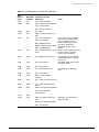
Common Commands
Table 6 describes common commands used to manage the switch. Commands specific to a particular
feature are described in the other chapters of this guide.
Table 6: Common Commands
Command
Description
clear session <number>
Terminates a Telnet session from the
switch.
config account <username> {encrypted}
{<password>}
Configures a user account password.
Passwords must have a minimum of 1
character and can have a maximum of 32
characters. User names and passwords
are case-sensitive.
config banner
Configures the banner string. You can
enter up to 24 rows of 79-column text that
is displayed before the login prompt of
each session. Press [Return] at the
beginning of a line to terminate the
command and apply the banner. To clear
the banner, press [Return] at the beginning
of the first line.
config ports <portlist> auto off {speed [10 | 100 |
1000]} duplex [half | full]
Manually configures the port speed and
duplex setting of one or more ports on a
switch.
config ssh2 key {pregenerated}
Generates the SSH2 host key.
28
Summit 300-48 Switch Software User Guide
Common Commands
Table 6: Common Commands (continued)
Command
Description
config sys-recovery-level [none | critical | all]
Configures a recovery option for instances
where an exception occurs in
ExtremeWare. Specify one of the
following:
•
none — Recovery without system
reboot.
•
critical — ExtremeWare logs an
error to the syslog, and reboots the
system after critical exceptions.
•
all — ExtremeWare logs an error to
the syslog, and reboots the system
after any exception.
The default setting is none.
config time <date> <time>
Configures the system date and time. The
format is as follows:
mm/dd/yyyy hh:mm:ss
The time uses a 24-hour clock format. You
cannot set the year past 2036.
config timezone <gmt_offset> {autodst | noautodst}
Configures the time zone information to
the configured offset from GMT time. The
format of gmt_offset is +/- minutes from
GMT time. Specify:
•
autodst — Enables automatic
Daylight Savings Time change.
•
nosautodst — Disables automatic
Daylight Savings Time change.
The default setting is autodst.
config vlan <name> ipaddress <ip_address>
{<mask>}
Configures an IP address and subnet
mask for a VLAN.
create account [admin | user] <username>
{encrypted} {<password>}
Creates a user account. This command is
available to admin-level users and to users
with RADIUS command authorization. The
username is between 1 and 32 characters,
the password is between 0 and 16
characters.
create vlan <name>
Creates a VLAN.
delete account <username>
Deletes a user account.
delete vlan <name>
Deletes a VLAN.
disable bootp vlan [<name> | all]
Disables BOOTP for one or more VLANs.
disable cli-config-logging
Disables logging of CLI commands to the
Syslog.
disable clipaging
Disables pausing of the screen display
when a show command output reaches
the end of the page.
disable idletimeouts
Disables the timer that disconnects all
sessions. Once disabled, console sessions
remain open until the switch is rebooted or
you logoff. Telnet sessions remain open
until you close the Telnet client.
disable ports <portlist>
Disables a port on the switch.
Summit 300-48 Switch Software User Guide
29
Accessing the Switch
Table 6: Common Commands (continued)
Command
Description
disable ssh2
Disables SSH2 access to the switch.
disable telnet
Disables Telnet access to the switch.
enable bootp vlan [<name> | all]
Enables BOOTP for one or more VLANs.
enable cli-config-logging
Enables the logging of CLI configuration
commands to the Syslog for auditing
purposes. The default setting is enabled.
enable clipaging
Enables pausing of the screen display
when show command output reaches the
end of the page. The default setting is
enabled.
enable idletimeouts
Enables a timer that disconnects all
sessions (both Telnet and console) after
20 minutes of inactivity. The default setting
is disabled.
enable ssh2 access-profile [<name> | none] {port
<tcp_port_number>}
Enables SSH2 sessions. By default, SSH2
uses TCP port number 22.
enable telnet access-profile [<name> | none] {port
<tcp_port_number>}
Enables Telnet access to the switch. By
default, Telnet uses TCP port number 23.
history
Displays the previous 49 commands
entered on the switch.
show banner
Displays the user-configured banner.
unconfig switch {all}
Resets all switch parameters (with the
exception of defined user accounts, and
date and time information) to the factory
defaults. If you specify the keyword all,
the switch erases the currently selected
configuration image in flash memory and
reboots. As a result, all parameters are
reset to default settings.
Configuring Management Access
ExtremeWare supports the following two levels of management:
• User
• Administrator
In addition to the management levels, you can optionally use an external RADIUS server to provide CLI
command authorization checking for each command. For more information on RADIUS, see “RADIUS
Client” in Chapter 3, “Managing the Switch”.
30
Summit 300-48 Switch Software User Guide
Configuring Management Access
User Account
A user-level account has viewing access to all manageable parameters, with the exception of:
• User account database.
• SNMP community strings.
A user-level account can use the ping command to test the ability to reach devices, and change the
password assigned to the account name. If you have logged on with user capabilities, the command-line
prompt ends with a (>) sign. For example:
Summit 300-48:2>
Administrator Account
An administrator-level account can view and change all switch parameters. It can also add and delete
users, and change the password associated with any account name. The administrator can disconnect a
management session that has been established by way of a Telnet connection. If this happens, the user
logged on by way of the Telnet connection is notified that the session has been terminated.
If you have logged on with administrator capabilities, the command-line prompt ends with a (#) sign.
For example:
Summit 300-48:18#
Prompt Text
The prompt text is taken from the SNMP sysname setting. The number that follows the colon indicates
the sequential line/command number.
If an asterisk (*) appears in front of the command-line prompt, it indicates that you have outstanding
configuration changes that have not been saved. For example:
*Summit 300-48:19#
Default Accounts
By default, the switch is configured with two accounts, as shown in Table 7.
Table 7: Default Accounts
Account Name
Access Level
admin
This user can access and change all manageable
parameters. The admin account cannot be deleted.
user
This user can view (but not change) all manageable
parameters, with the following exceptions:
Summit 300-48 Switch Software User Guide
•
This user cannot view the user account database.
•
This user cannot view the SNMP community strings.
31
Accessing the Switch
Changing the Default Password
Default accounts do not have passwords assigned to them. Passwords must have a minimum of four
characters and can have a maximum of 12 characters.
NOTE
User names and passwords are case-sensitive.
To add a password to the default admin account, follow these steps:
1 Log in to the switch using the name admin.
2 At the password prompt, press [Return].
3 Add a default admin password by entering the following command:
config account admin
4 Enter the new password at the prompt.
5 Re-enter the new password at the prompt.
To add a password to the default user account, follow these steps:
1 Log in to the switch using the name admin.
2 At the password prompt, press [Return], or enter the password that you have configured for the
admin account.
3 Add a default user password by entering the following command:
config account user
4 Enter the new password at the prompt.
5 Re-enter the new password at the prompt.
NOTE
If you forget your password while logged out of the command-line interface, contact your local technical
support representative, who will advise on your next course of action.
Creating a Management Account
The switch can have a total of 16 management accounts. You can use the default names (admin and
user), or you can create new names and passwords for the accounts. Passwords can have a minimum of
0 characters and can have a maximum of 31 characters.
To create a new account, follow these steps:
1 Log in to the switch as admin.
2 At the password prompt, press [Return], or enter the password that you have configured for the
admin account.
3 Add a new user by using the following command:
create account [admin | user] <username>
4 Enter the password at the prompt.
5 Re-enter the password at the prompt.
32
Summit 300-48 Switch Software User Guide
Domain Name Service Client Services
Viewing Accounts
To view the accounts that have been created, you must have administrator privileges. Use the following
command to see the accounts:
show accounts
Deleting an Account
To delete a account, you must have administrator privileges. To delete an account, use the following
command:
delete account <username>
NOTE
The account name admin cannot be deleted.
Domain Name Service Client Services
The Domain Name Service (DNS) client in ExtremeWare augments the following commands to allow
them to accept either IP addresses or host names:
• telnet
• download [bootrom | configuration | image]
• upload configuration
• ping
• traceroute
In addition, the nslookup utility can be used to return the IP address of a hostname.
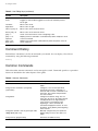
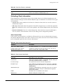
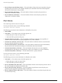
Table 8 describes the commands used to configure DNS.
Table 8: DNS Commands
Command
Description
config dns-client add <ipaddress>
Adds a DNS name server(s) to the
available server list for the DNS client. Up
to three name servers can be configured.
config dns-client default-domain <domain_name>
Configures the domain that the DNS client
uses if a fully qualified domain name is not
entered. For example, if the default
domain is configured to be foo.com,
executing ping bar searches for
bar.foo.com.
config dns-client delete <ipaddress>
Removes a DNS server.
nslookup <hostname>
Displays the IP address of the requested
host.
show dns-client
Displays the DNS configuration.
Summit 300-48 Switch Software User Guide
33
Accessing the Switch
Checking Basic Connectivity
The switch offers the following commands for checking basic connectivity:
• ping
• traceroute
Ping
The ping command enables you to send Internet Control Message Protocol (ICMP) echo messages to a
remote IP device. The ping command is available for both the user and administrator privilege level.
The ping command syntax is:
ping {continuous} {start-size <number>} [<ip_address> | <hostname>] {from
<src_address> | with record-route | from <src_ipaddress> with record-route}
Options for the ping command are described in Table 9.
Table 9: Ping Command Parameters
Parameter
Description
continuous
Specifies ICMP echo messages to be sent continuously.
This option can be interrupted by pressing any key.
start-size
Specifies the size of the ICMP request. If the
start-size is specified, transmits ICMP requests
using 1 byte increments, per packet.
<ipaddress>
Specifies the IP address of the host.
<hostname>
Specifies the name of the host. To use the hostname,
you must first configure DNS.
from
Uses the specified source address in the ICMP packet.
If not specified, the address of the transmitting interface
is used.
with record-route
Decodes the list of recorded routes and displays them
when the ICMP echo reply is received.
If a ping request fails, the switch continues to send ping messages until interrupted. Press any key to
interrupt a ping request.
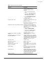
Traceroute
The traceroute command enables you to trace the routed path between the switch and a destination
endstation. The traceroute command syntax is:
traceroute [<ip_address> | <hostname>] {from <src_ipaddress>} {ttl <TTL>} {port
<port>}
where:
• ip_address is the IP address of the destination endstation.
• hostname is the hostname of the destination endstation. To use the hostname, you must first
configure DNS.
34
Summit 300-48 Switch Software User Guide
Checking Basic Connectivity
• from uses the specified source address in the ICMP packet. If not specified, the address of the
transmitting interface is used.
• ttl configures the switch to trace up to the time-to-live number of the switch.
• port uses the specified UDP port number.
Summit 300-48 Switch Software User Guide
35
Accessing the Switch
36
Summit 300-48 Switch Software User Guide
3
Managing the Switch
This chapter describes the following topics:
• Overview on page 37
• Using the Console Interface on page 38
• Using Telnet on page 38
• Using Secure Shell 2 (SSH2) on page 41
• Using SNMP on page 42
• Authenticating Users on page 45
• Using ExtremeWare Vista on page 49
• Using the Simple Network Time Protocol on page 53
Overview
Using ExtremeWare, you can manage the switch using the following methods:
• Access the CLI by connecting a terminal (or workstation with terminal-emulation software) to the
console port.
• Access the switch remotely using TCP/IP through one of the switch ports. Remote access includes:
— Telnet using the CLI interface.
— SSH2 using the CLI interface.
— SNMP access using ExtremeWare Enterprise Manager or another SNMP manager.
— Web access using ExtremeWare Vista.
The switch supports up to the following number of concurrent user sessions:
• One console session
• Eight Telnet sessions
• Eight SSH2 sessions
Summit 300-48 Switch Software User Guide
37
Managing the Switch
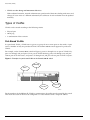
Using the Console Interface
The CLI built into the switch is accessible by way of the 9-pin, RS-232 port labeled console, located on
the front of the Summit 300-48 switch.
After the connection has been established, you will see the switch prompt and you can log in.
Using Telnet
Any workstation with a Telnet facility should be able to communicate with the switch over a TCP/IP
network.
Up to eight active Telnet sessions can access the switch concurrently. If idletimeouts is enabled, the
Telnet connection will time out after 20 minutes of inactivity. If a connection to a Telnet session is lost
inadvertently, the switch terminates the session within two hours.
Before you can start a Telnet session, you must configure the switch IP parameters. See “Configuring
Switch IP Parameters” on page 38 for more information. Telnet is enabled by default.
To open the Telnet session, you must specify the IP address of the device that you want to manage.
Check the user manual supplied with the Telnet facility if you are unsure of how to do this.
After the connection has been established, you will see the switch prompt and you may log in.
Connecting to Another Host Using Telnet
You can Telnet from the current CLI session to another host using the following command:
telnet [<ipaddress> | <hostname>] {<port_number>}
If the TCP port number is not specified, the Telnet session defaults to port 23. Only VT100 emulation is
supported.
Configuring Switch IP Parameters
To manage the switch by way of a Telnet connection or by using an SNMP Network Manager, you must
first configure the switch IP parameters.
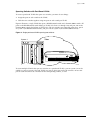
Using a BOOTP Server
If you are using IP and you have a Bootstrap Protocol (BOOTP) server set up correctly on your network,
you must add the following information to the BOOTP server:
• Switch Media Access Control (MAC) address, found on the rear label of the switch
• IP address
• Subnet address mask (optional)
After this is done, the IP address and subnet mask for the switch will be downloaded automatically.
You can then start managing the switch without further configuration.
38
Summit 300-48 Switch Software User Guide
Using Telnet
You can enable BOOTP on a per-VLAN basis by using the following command:
enable bootp vlan [<name> | all]
By default, BOOTP is disabled on the default VLAN.
To enable the forwarding of BOOTP and Dynamic Host Configuration Protocol (DHCP) requests, use
the following command:
enable bootprelay
If you configure the switch to use BOOTP, the switch IP address is not retained through a power cycle,
even if the configuration has been saved. To retain the IP address through a power cycle, you must
configure the IP address of the VLAN.
All VLANs within a switch that are configured to use BOOTP to get their IP address use the same MAC
address. Therefore, if you are using DHCP/BOOTP relay through a router, the BOOTP server must be
capable of differentiating its relay based on the gateway portion of the BOOTP packet.
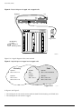
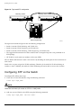
Manually Configuring the IP Settings
If you are using IP without a BOOTP server, you must enter the IP parameters for the switch in order
for the SNMP Network Manager, Telnet software, or Web interface to communicate with the device. To
assign IP parameters to the switch, you must perform the following tasks:
• Log in to the switch with administrator privileges.
• Assign an IP address and subnet mask to a VLAN.
The switch comes configured with a default VLAN named default. To use Telnet or an SNMP
Network Manager, you must have at least one VLAN on the switch, and it must be assigned an IP
address and subnet mask. IP addresses are always assigned to a VLAN. The switch can be assigned
multiple IP addresses.
NOTE
For information on creating and configuring VLANs, see Chapter 5, “Virtual LANs (VLANs)”.
To manually configure the IP settings, follow these steps:
1 Connect a terminal or workstation running terminal-emulation software to the console port.
2 At your terminal, press [Return] one or more times until you see the login prompt.
3 At the login prompt, enter your user name and password. Note that they are both case-sensitive.
Ensure that you have entered a user name and password with administrator privileges.
— If you are logging in for the first time, use the default user name admin to log in with
administrator privileges. For example:
login: admin
Administrator capabilities enable you to access all switch functions. The default user names have
no passwords assigned.
— If you have been assigned a user name and password with administrator privileges, enter them at
the login prompt.
4 At the password prompt, enter the password and press [Return].
Summit 300-48 Switch Software User Guide
39
Managing the Switch
When you have successfully logged in to the switch, the command-line prompt displays the name of
the switch in its prompt.
5 Assign an IP address and subnetwork mask for the default VLAN by using the following command:
config vlan <name> ipaddress <ipaddress> {<subnet_mask>}
For example:
config vlan default ipaddress 123.45.67.8 255.255.255.0
Your changes take effect immediately.
NOTE
As a general rule, when configuring any IP addresses for the switch, you can express a subnet mask by
using dotted decimal notation, or by using classless inter-domain routing notation (CIDR). CIDR uses a
forward slash plus the number of significant bits in the subnet mask. Using CIDR notation, the
command identical to the one above would be:
config vlan default ipaddress 123.45.67.8 / 24
6 Configure the default route for the switch using the following command:
config iproute add default <gateway> {<metric>}
For example:
config iproute add default 123.45.67.1
7 Save your configuration changes so that they will be in effect after the next switch reboot, by typing:
save
8 When you are finished using the facility, log out of the switch by typing:
logout or quit
Disconnecting a Telnet Session
An administrator-level account can disconnect a Telnet management session. If this happens, the user
logged in by way of the Telnet connection is notified that the session has been terminated.
To terminate a Telnet session, follow these steps:
1 Log in to the switch with administrator privileges.
2 Determine the session number of the session you want to terminate by using the following
command:
show session
3 Terminate the session by using the following command:
clear session <session_number>
40
Summit 300-48 Switch Software User Guide
Using Secure Shell 2 (SSH2)
Controlling Telnet Access
By default, Telnet services are enabled on the switch. To display the status of Telnet, use the following
command:
show management
You can choose to disable Telnet by using the following command:
disable telnet
To re-enable Telnet on the switch, at the console port use the following:
enable telnet
You must be logged in as an administrator to enable or disable Telnet.
Using Secure Shell 2 (SSH2)
Secure Shell 2 (SSH2) is a feature of ExtremeWare that allows you to encrypt session data between the
switch and a network administrator using SSH2 client software. The ExtremeWare SSH2 switch
application is based on the Data Fellows™ SSH2 server implementation. It is highly recommended that
you use the F-Secure SSH client products from Data Fellows corporation. These applications are
available for most operating systems. For more information, refer to the Data Fellows website at:
http://www.datafellows.com.
NOTE
SSH2 is compatible with the Data Fellows SSH2 client version 2.0.12 or above. SSH2 is not compatible
with SSH1.
Enabling SSH2 for Inbound Switch Access
Because SSH2 is currently under U.S. export restrictions, you must first obtain a security-enabled
version of the ExtremeWare software from Extreme Networks before you can enable SSH2. The
procedure for obtaining a security-enabled version of the ExtremeWare software is described in
Chapter 1.
You must enable SSH2 on the switch before you can connect to it using an external SSH2 client.
Enabling SSH2 involves two steps:
• Enabling SSH2 access, which may include specifying an access profile, and specifying a TCP port to
be used for communication.
By default, if you have a security license, SSH2 is disabled using TCP port 22, with no restrictions on
client access.
• Generating or specifying an authentication key for the SSH2 session.
To enable SSH2, use the following command:
enable ssh2 {access-profile [<access_profile> | none] {port <tcp_port_number>}}
Summit 300-48 Switch Software User Guide
41
Managing the Switch
You can specify a list of predefined clients that are allowed SSH2 access to the switch. To do this, you
must create an access profile that contains a list of allowed IP addresses. For more information on
creating access profiles, refer to Chapter 10.
You can also specify a TCP port number to be used for SSH2 communication. By default the TCP port
number is 22.
The supported cipher is 3DES-CBC. The supported key exchange is DSA.
An authentication key must be generated before the switch can accept incoming SSH2 sessions. This can
be done automatically by the switch, or you can enter a previously generated key. To have the key
generated by the switch, use the following command:
config ssh2 key
You are prompted to enter information to be used in generating the key. The key generation process
takes approximately ten minutes. Once the key has been generated, you should save your configuration
to preserve the key.
To use a key that has been previously created, use the following command:
config ssh2 key pregenerated
You are prompted to enter the pregenerated key.
The key generation process generates the SSH2 private host key. The SSH2 public host key is derived
from the private host key, and is automatically transmitted to the SSH2 client at the beginning of an
SSH2 session.
Before you initiate a session from an SSH2 client, ensure that the client is configured for any nondefault
access list or TCP port information that you have configured on the switch. Once these tasks are
accomplished, you may establish an SSH2-encrypted session with the switch. Clients must have a valid
user name and password on the switch in order to log into the switch after the SSH2 session has been
established.
For additional information on the SSH protocol refer to [FIPS-186] Federal Information Processing
Standards Publication (FIPSPUB) 186, Digital Signature Standard, 18 May 1994. This can be download
from: ftp://ftp.cs.hut.fi/pub/ssh. General technical information is also available from:
http://www.ssh.fi
Using SNMP
Any Network Manager running the Simple Network Management Protocol (SNMP) can manage the
switch, provided the Management Information Base (MIB) is installed correctly on the management
station. Each Network Manager provides its own user interface to the management facilities.
The following sections describe how to get started if you want to use an SNMP manager. It assumes
you are already familiar with SNMP management. Extreme Networks products support SNMP v1 and
SNMP v2C.
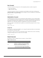
Accessing Switch Agents
To have access to the SNMP agent residing in the switch, at least one VLAN must have an IP address
assigned to it.
42
Summit 300-48 Switch Software User Guide
Using SNMP
Supported MIBs
In addition to private MIBs, the switch supports the standard MIBs listed in Appendix B.
Configuring SNMP Settings
The following SNMP parameters can be configured on the switch:
• Authorized trap receivers — An authorized trap receiver can be one or more network management
stations on your network. The switch sends SNMP traps to all trap receivers. You can have a
maximum of 16 trap receivers configured for each switch. Entries in this list can also be created,
modified, and deleted using the RMON2 trapDestTable MIB variable, as described in RFC 2021.
• Community strings — The community strings allow a simple method of authentication between the
switch and the remote Network Manager. There are two types of community strings on the switch.
Read community strings provide read-only access to the switch. The default read-only community
string is public. Read-write community strings provide read and write access to the switch. The
default read-write community string is private. A total of eight community strings can be configured
on the switch. The community string for all authorized trap receivers must be configured on the
switch for the trap receiver to receive switch-generated traps. SNMP community strings can contain
up to 127 characters.
• System contact (optional) — The system contact is a text field that enables you to enter the name of
the person(s) responsible for managing the switch.
• System name — The system name is the name that you have assigned to this switch. The default
name is the model name of the switch (for example, Summit1 switch).
• System location (optional) — Using the system location field, you can enter an optional location for
this switch.
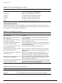
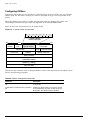
Table 10 describes SNMP configuration commands.
Table 10: SNMP Configuration Commands
Command
Description
config snmp add trapreceiver <ipaddress>
community <string>
Adds the IP address of a specified trap
receiver. The IP address can be a unicast,
multicast, or broadcast address. A
maximum of 16 trap receivers is allowed.
config snmp community [readonly | readwrite]
<string>
Adds an SNMP read or read/write
community string. The default readonly
community string is public. The default
readwrite community string is private.
Each community string can have a
maximum of 127 characters, and can be
enclosed by double quotation marks.
config snmp delete trapreceiver [<ip_address>
community <string> | all]
Deletes the IP address of a specified trap
receiver or all authorized trap receivers.
config snmp syscontact <string>
Configures the name of the system
contact. A maximum of 255 characters is
allowed.
config snmp syslocation <string>
Configures the location of the switch. A
maximum of 255 characters is allowed.
Summit 300-48 Switch Software User Guide
43
Managing the Switch
Table 10: SNMP Configuration Commands (continued)
Command
Description
config snmp sysname <string>
Configures the name of the switch. A
maximum of 32 characters is allowed. The
default sysname is the model name of the
device (for example, Summit 300-48).
The sysname appears in the switch
prompt.
disable snmp access
Disables SNMP on the switch. Disabling
SNMP access does not affect the SNMP
configuration (for example, community
strings).
disable snmp traps
Prevents SNMP traps from being sent
from the switch. Does not clear the SNMP
trap receivers that have been configured.
enable snmp access
Turns on SNMP support for the switch.
enable snmp traps
Turns on SNMP trap support.
unconfig management
Restores default values to all
management-related entries.
Displaying SNMP Settings
To display the SNMP settings configured on the switch, use the following command:
show management
This command displays the following information:
• Enable/disable state for Telnet, SSH2, and SNMP, and web
• SNMP community strings
• Authorized SNMP station list
• SNMP trap receiver list
• RMON polling configuration
• Login statistics
• CLI idle timeouts
• CLI paging
• CLI configuration logging
44
Summit 300-48 Switch Software User Guide
Authenticating Users
Authenticating Users
ExtremeWare provides a Radius client to authenticate switch admin users who login to the switch:
RADIUS Client
Remote Authentication Dial In User Service (RADIUS, RFC 2138) is a mechanism for authenticating and
centrally administrating access to network nodes. The ExtremeWare RADIUS client implementation
allows authentication for Telnet or console access to the switch.
You can define a primary and secondary RADIUS server for the switch to contact. When a user
attempts to login using Telnet, http, or the console, the request is relayed to the primary RADIUS server,
and then to the secondary RADIUS server, if the primary does not respond. If the RADIUS client is
enabled, but access to the RADIUS primary an secondary server fails, the switch uses its local database
for authentication.
The privileges assigned to the user (admin versus nonadmin) at the RADIUS server take precedence
over the configuration in the local switch database.
Configuring RADIUS Client
You can define primary and secondary server communication information, and for each RADIUS server,
the RADIUS port number to use when talking to the RADIUS server. The default port value is 1645. The
client IP address is the IP address used by the RADIUS server for communicating back to the switch.
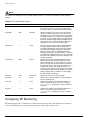
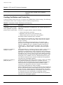
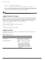
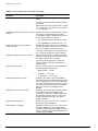
RADIUS commands are described in Table 11.
Table 11: RADIUS Commands
Command
Description
enable radius
Enables RADIUS globally for wired and wireless access.
disable radius
Disables RADIUS globally for wired and wireless access.
enable radius network-access
Enables RADIUS for wireless access only.
disable radius network-access
Disables RADIUS for wireless access only.
enable radius switch-access
Enables RADIUS for switch access only. In order to obtain wireless
access as well, the enable radius network-access command
must be used.
disable radius switch-access
Disables RADIUS for switch access only.
Summit 300-48 Switch Software User Guide
45
Managing the Switch
Table 11: RADIUS Commands (continued)
Command
Description
config radius [primary | secondary]
server [<ipaddress> | <hostname>]
{<udp_port>} client-ip <ipaddress>
Configures the primary and secondary RADIUS server. Specify the
following:
•
[primary | secondary] — Configure either the primary or
secondary RADIUS server.
•
[<ipaddress> | <hostname>] — The IP address or hostname
of the server being configured.
•
<udp_port> — The UDP port to use to contact the RADUIS server.
The default UDP port setting is 1645.
•
client-ip <ipaddress> — The IP address used by the switch
to identify itself when communicating with the RADIUS server.
The RADIUS server defined by this command is used for user name
authentication and CLI command authentication.
config radius [primary | secondary]
shared-secret {encrypted} <string>
Configures the authentication string used to communicate with the
RADIUS server.
show radius
Displays the current RADIUS client configuration and statistics.
unconfig radius {server [primary |
secondary]}
Unconfigures the radius client configuration.
RADIUS RFC 2138 Attributes
The RADIUS RFC 2138 optional attributes supported are as follows:
• User-Name
• User-Password
• Service-Type
• Login-IP-Host
RADIUS Server Configuration Example (Merit)
Many implementations of RADIUS server use the publicly available Merit© AAA server application,
available on the World Wide Web at:
http://www.merit.edu/aaa
Included below are excerpts from relevant portions of a sample Merit RADIUS server implementation.
The example shows excerpts from the client and user configuration files. The client configuration file
(ClientCfg.txt) defines the authorized source machine, source name, and access level. The user
configuration file (users) defines username, password, and service type information.
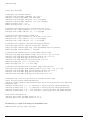
ClientCfg.txt
#Client Name
#---------------#10.1.2.3:256
#pm1
#pm2
#merit.edu/homeless
46
Key
[type]
[version]
--------------- -------------- --------test
type = nas
v2
%^$%#*(&!(*&)+
type=nas
:-):-(;^):-}!
type nas
hmoemreilte.ses
[prefix]
-------pfx
pm1.
pm2.
Summit 300-48 Switch Software User Guide
Authenticating Users
#homeless
#xyz.merit.edu
#anyoldthing:1234
10.202.1.3
10.203.1.41
10.203.1.42
10.0.52.14
testing
moretesting
whoknows?
andrew-linux
eric
eric
samf
type proxy
v1
type=Ascend:NAS v1
type=NAS+RAD_RFC+ACCT_RFC
type=nas
type=nas
type=nas
type=nas
users
user
Password
Filter-Id =
admin
Password
Filter-Id =
= ""
"unlim"
= "", Service-Type = Administrative
"unlim"
eric
Password = "", Service-Type = Administrative
Filter-Id = "unlim"
albert
Password = "password", Service-Type = Administrative
Filter-Id = "unlim"
samuel
Password = "password", Service-Type = Administrative
Filter-Id = "unlim"
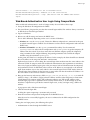
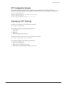
RADIUS Per-Command Configuration Example
Building on this example configuration, you can use RADIUS to perform per-command authentication
to differentiate user capabilities. To do so, use the Extreme-modified RADIUS Merit software that is
available from the Extreme Networks web server at
http://www.extremenetworks.com/extreme/support/otherapps.htm or by contacting Extreme
Networks technical support. The software is available in compiled format for Solaris™ or Linux™
operating systems, as well as in source code format. For all clients that use RADIUS per-command
authentication, you must add the following type to the client file:
type:extreme:nas + RAD_RFC + ACCT_RFC
Within the users configuration file, additional keywords are available for Profile-Name and
Extreme-CLI-Authorization. To use per-command authentication, enable the CLI authorization
function and indicate a profile name for that user. If authorization is enabled without specifying a valid
profile, the user is unable to perform any commands.
Next, define the desired profiles in an ASCII configuration file called profiles. This file contains
named profiles of exact or partial strings of CLI commands. A named profile is linked with a user
through the users file. A profile with the permit on keywords allows use of only the listed commands.
A profile with the deny keyword allows use of all commands except the listed commands.
CLI commands can be defined easily in a hierarchal manner by using an asterisk (*) to indicate any
possible subsequent entry. The parser performs exact string matches on other text to validate
commands. Commands are separated by a comma (,) or newline.
Looking at the following example content in profiles for the profile named PROFILE1, which uses the
deny keyword, the following attributes are associated with the user of this profile:
• Cannot use any command starting with enable.
• Cannot issue the disable ipforwarding command.
Summit 300-48 Switch Software User Guide
47
Managing the Switch
• Cannot issue a show switch command.
• Can perform all other commands.
We know from the users file that this applies to the users albert and lulu. We also know that eric is
able to log in, but is unable to perform any commands, because he has no valid profile assigned.
In PROFILE2, a user associated with this profile can use any enable command, the clear counter
command and the show management command, but can perform no other functions on the switch. We
also know from the users file that gerald has these capabilities.
The following lists the contents of the file users with support for per-command authentication:
user
Password = ""
Filter-Id = "unlim"
admin
Password = "", Service-Type = Administrative
Filter-Id = "unlim"
eric
Password = "", Service-Type = Administrative, Profile-Name = ""
Filter-Id = "unlim"
Extreme:Extreme-CLI-Authorization = Enabled
albert Password = "", Service-Type = Administrative, Profile-Name =
"Profile1"
Filter-Id = "unlim"
Extreme:Extreme-CLI-Authorization = Enabled
lulu
Password = "", Service-Type = Administrative, Profile-Name =
"Profile1"
Filter-Id = "unlim"
Extreme:Extreme-CLI-Authorization = Enabled
gerald
Password = "", Service-Type = Administrative, Profile-Name "Profile2"
Filter-Id = "unlim"
Extreme:Extreme-CLI-Authorization = Enabled
Contents of the file “profiles”:
PROFILE1 deny
{
enable *, disable ipforwarding
show switch
}
PROFILE2
{
enable *, clear counters
show
management
}
PROFILE3 deny
{
create vlan *, configure iproute *, disable *, show fdb
delete *, configure rip add
}
48
Summit 300-48 Switch Software User Guide
Using ExtremeWare Vista
Using ExtremeWare Vista
The ExtremeWare Vista™ device-management software that runs on the switch allows you to access the
switch over a TCP/IP network using a standard web browser. Any properly configured standard web
browser that supports frames and JavaScript (such as Netscape Navigator 3.0 or above, or Microsoft
Internet Explorer 3.0 or above) can be used to manage the switch.
ExtremeWare Vista provides a subset of the command-line interface (CLI) commands available for
configuring and monitoring the switch. If a particular command is not available using ExtremeWare
Vista, you must use the CLI to access the desired functionality.
To use ExtremeWare Vista, at least one VLAN must be assigned an IP address.
NOTE
For more information on assigning an IP address, see “Configuring Switch IP Parameters” on page 38.
The default home page of the switch can be accessed using the following command:
http://<ipaddress>
When you access the home page of the switch, you are presented with the Logon screen.
Controlling Web Access
By default, web access is enabled on the switch. To configure Vista web access to be disabled, use the
following command:
disable web
To display the status of web access, use the following command:
show management
To disable ExtremeWare Vista, use the following command:
disable web
To re-enable web access, use the enable web command.
By default, web access uses TCP port 80. To specify a different port, use the port option in the enable
web command.
NOTE
For more information on rebooting, see Appendix C.
Setting Up Your Browser
In general, the default settings that come configured on your browser work well with ExtremeWare
Vista. You can use the following recommended settings to improve the display features and
functionality of ExtremeWare Vista:
Summit 300-48 Switch Software User Guide
49
Managing the Switch
• After downloading a newer version of the switch image, clear the browser disk and memory cache
to see the updated menu screens. You must clear the cache while at the main ExtremeWare Vista
Logon screen, so that all underlying .GIF files are updated.
• Check for newer versions of stored pages. Every visit to the page should be selected as a cache
setting.
If you are using Netscape Navigator, configure the cache option to check for changes “Every Time”
you request a page.
If you are using Microsoft Internet Explorer, configure the Temporary Internet Files setting to check
for newer versions of stored pages by selecting “Every visit to the page.”
• Images must be auto-loaded.
• Use a high-resolution monitor to maximize the amount of information displayed in the content
frame. The recommended resolution is 1024 x 768 pixels. You can also use 800 x 600 pixels.
• Turn off one or more of the browser toolbars to maximize the viewing space of the ExtremeWare
Vista content screen.
• If you will be using ExtremeWare Vista to send an email to the Extreme Networks Technical Support
department, configure the email settings in your browser.
• Configure the browser to use the following recommended fonts:
— Proportional font—Times New Roman
— Fixed-width font—Courier New
Accessing ExtremeWare Vista
To access the default home page of the switch, enter the following URL in your browser:
http://<ip_address>
When you access the home page of the system, you are presented with the Login screen. Enter your
user name and password in the appropriate fields, and click OK.
If you have entered the name and password of an administrator-level account, you have access to all
ExtremeWare Vista pages. If you have used a user-level account name and password, you only have
access to the Statistics and Support information.
If multiple people access the same switch using ExtremeWare Vista, you might see the following error
message:
Web:server busy
To correct this situation, log out of the switch and log in again.
Navigating ExtremeWare Vista
After logging in to the switch, the ExtremeWare Vista home page is displayed.
ExtremeWare Vista divides the browser screen into the following sections:
• Task frame
• Content frame
• Standalone buttons
50
Summit 300-48 Switch Software User Guide
Using ExtremeWare Vista
Task Frame
The task frame has two sections: menu buttons and submenu links. The four task menu buttons are:
• Configuration
• Statistics
• Support
• Logout
Below the task buttons are options. Options are specific to the task button that you select. When you
select an option, the information displayed in the content frame changes. However, when you select a
new task button, the content frame does not change until you select a new option.
NOTE
Submitting a configuration page with no change will result in an asterisk (*) appearing at the CLI
prompt, even though actual configuration values have not changed.
Content Frame
The content frame contains the main body of information in ExtremeWare Vista. For example, if you
select an option from the Configuration task button, enter configuration parameters in the content
frame. If you select the Statistics task button, statistics are displayed in the content frame.
Browser Controls. Browser controls include drop-down list boxes, check boxes, and multiselect list
boxes. A multiselect list box has a scrollbar on the right side of the box. Using a multiselect list box, you
can select a single item, all items, a set of contiguous items, or multiple noncontiguous items. Table 12
describes how to make selections from a multiselect list box.
Table 12: Multiselect List Box Key Definitions
Selection Type
Key Sequence
Single item
Click the item using the mouse.
All items
Click the first item, and drag to the last item.
Contiguous items
Click the first desired item, and drag to the last desired item.
Selected noncontiguous items
Hold down [Ctrl], click the first desired item, click the next desired item, and
so on.
Summit 300-48 Switch Software User Guide
51
Managing the Switch
Status Messages
Status messages are displayed at the top of the content frame. The four types of status messages are:
• Information—Displays information that is useful to know prior to, or as a result of, changing
configuration options.
• Warning—Displays warnings about the switch configuration.
• Error—Displays errors caused by incorrectly configured settings.
• Success—Displays informational messages after you click Submit. The message displayed reads,
“Request was submitted successfully.”
Standalone Buttons
At the bottom of some of the content frames is a section that contains standalone buttons. Standalone
buttons are used to perform tasks that are not associated with a particular configuration option. An
example of this is the Reboot Switch button.
Saving Changes
You can save your changes to nonvolatile storage in either of two ways using ExtremeWare Vista:
• Select Save Configuration from the Configuration task button, Switch option.
This field contains a drop-down list box that allows you to select either the primary or secondary
configuration area. After you select the configuration area, click Submit to save the changes.
• Click the Logout button.
If you attempt to log out without saving your changes, ExtremeWare Vista prompts you to save your
changes.
If you select Yes, the changes are saved to the selected configuration area. To change the selected
configuration area, you must go to the Configuration task button, Switch option.
Filtering Information
Some pages have a Filter button. The Filter button is used to display a subset of information on a given
page. For example, on the OSPF configuration page, you can configure authentication based on the
VLAN, area identifier, or virtual link. After you select a filtering option and click the Filter button, the
form that provides the configuration options displays the available interfaces in the drop-down menu,
based on your filtering selection.
Similarly, in certain Configuration and Statistics pages, information is shown based on a particular slot.
Because modular switches allow you to preconfigure modules without having them physically available
in the chassis, the configuration pages offer a drop-down menu to select any module card that has been
configured on the system, whether or not the module is physically available. By default, information for
the first configured module that is found in the chassis is displayed on the page. You can configure
available slots and ports by filtering on a selected module from the Sort by Slot drop-down menu.
On the Statistics pages, you can only view information for cards that are configured and physically
inserted into the chassis. On these pages, the Sort by Slot drop-down menu displays only these
modules.
52
Summit 300-48 Switch Software User Guide
Using the Simple Network Time Protocol
Do a GET When Configuring a VLAN
When configuring a VLAN using ExtremeWare Vista, prior to editing the VLAN configuration, you
must first click the get button to ensure that subsequent edits are applied to the correct VLAN. If you
do not click the get button and you submit the changes, the changes will be made to the VLAN that
was previously displayed.
If you configure a VLAN and then delete it, the default VLAN is shown in the VLAN name window, but
the VLAN information contained in the lower portion of the page is not updated. Click the get button
to update the display.
Sending Screen Output to Extreme Networks
If Extreme Networks requests that you email the output of a particular ExtremeWare Vista screen,
follow these steps:
1 Click the content frame of the screen that you must send.
2 From the Netscape Navigator File menu, select Save Frame As and enter a name for the file.
From the Microsoft Internet Explorer 3.0 File menu, select Save As and enter a name for the file.
From Microsoft Internet Explorer 4.0, right-click in the content frame, select View Source, and save
the HTML text by copying it and pasting it into a text editor.
3 Attach the file to the email message that you are sending to Extreme Networks.
Using the Simple Network Time Protocol
ExtremeWare supports the client portion of the Simple Network Time Protocol (SNTP) Version 3 based
on RFC1769. SNTP can be used by the switch to update and synchronize its internal clock from a
Network Time Protocol (NTP) server. When enabled, the switch sends out a periodic query to the
indicated NTP server, or the switch listens to broadcast NTP updates. In addition, the switch supports
the configured setting for Greenwich Mean time (GMT) offset and the use of Daylight Savings Time.
These features have been tested for year 2000 compliance.
Configuring and Using SNTP
To use SNTP, follow these steps:
1 Identify the host(s) that are configured as NTP server(s). Additionally, identify the preferred method
for obtaining NTP updates. The options are for the NTP server to send out broadcasts, or for
switches using NTP to query the NTP server(s) directly. A combination of both methods is possible.
You must identify the method that should be used for the switch being configured.
2 Configure the Greenwich Mean Time (GMT) offset and Daylight Savings Time preference. The
command syntax to configure GMT offset and usage of Daylight Savings is as follows:
config timezone <GMT_offset> {autodst | noautodst}
The GMT_OFFSET is in +/- minutes from the GMT time. Automatic Daylight Savings Time (DST)
changes can be enabled or disabled. The default setting is enabled.
3 Enable the SNTP client using the following command:
enable sntp-client
Summit 300-48 Switch Software User Guide
53
Managing the Switch
Once enabled, the switch sends out a periodic query to the NTP servers defined later (if configured)
or listens to broadcast NTP updates from the network. The network time information is
automatically saved into the on-board real-time clock.
4 If you would like this switch to use a directed query to the NTP server, configure the switch to use
the NTP server(s). If the switch listens to NTP broadcasts, skip this step. To configure the switch to
use a directed query, use the following command:
config sntp-client [primary | secondary] server [<ip_address> | <hostname>]
NTP queries are first sent to the primary server. If the primary server does not respond within 1
second, or if it is not synchronized, the switch queries the secondary server (if one is configured). If
the switch cannot obtain the time, it restarts the query process. Otherwise, the switch waits for the
sntp-client update interval before querying again.
5 Optionally, the interval for which the SNTP client updates the real-time clock of the switch can be
changed using the following command:
config sntp-client update-interval <seconds>
The default sntp-client update-interval value is 64 seconds.
6 You can verify the configuration using the following commands:
— show sntp-client
This command provides configuration and statistics associated with SNTP and its connectivity to
the NTP server.
— show switch
This command indicates the GMT offset, Daylight Savings Time, and the current local time.
NTP updates are distributed using GMT time. To properly display the local time in logs and other
timestamp information, the switch should be configured with the appropriate offset to GMT based on
geographical location. Table 13 describes GMT offsets.
Table 13: Greenwich Mean Time Offsets
GMT
Offset in
Hours
GMT Offset Common Time Zone
in Minutes References
+0:00
+0
GMT - Greenwich Mean
UT or UTC - Universal
(Coordinated)
Cities
London, England; Dublin, Ireland;
Edinburgh, Scotland; Lisbon,
Portugal; Reykjavik, Iceland;
Casablanca, Morocco
WET - Western European
-1:00
-60
WAT - West Africa
-2:00
-120
AT - Azores
-3:00
-180
-4:00
-240
AST - Atlantic Standard
Caracas; La Paz
-5:00
-300
EST - Eastern Standard
Bogota, Columbia; Lima, Peru;
New York, NY, Trevor City, MI
USA
-6:00
-360
CST - Central Standard
Mexico City, Mexico
-7:00
-420
MST - Mountain Standard
Saskatchewan, Canada
-8:00
-480
PST - Pacific Standard
Los Angeles, CA, Cupertino, CA,
Seattle, WA USA
54
Azores, Cape Verde Islands
Brasilia, Brazil; Buenos Aires,
Argentina; Georgetown, Guyana;
Summit 300-48 Switch Software User Guide
Using the Simple Network Time Protocol
Table 13: Greenwich Mean Time Offsets (continued)
GMT
Offset in
Hours
GMT Offset Common Time Zone
in Minutes References
-9:00
-540
YST - Yukon Standard
-10:00
-600
AHST - Alaska-Hawaii Standard
Cities
CAT - Central Alaska
HST - Hawaii Standard
-11:00
-660
NT - Nome
-12:00
-720
IDLW - International Date Line
West
+1:00
+60
CET - Central European
+2:00
+120
EET - Eastern European, Russia Athens, Greece; Helsinki, Finland;
Zone 1
Istanbul, Turkey; Jerusalem,
Israel; Harare, Zimbabwe
+3:00
+180
BT - Baghdad, Russia Zone 2
Kuwait; Nairobi, Kenya; Riyadh,
Saudi Arabia; Moscow, Russia;
Tehran, Iran
+4:00
+240
ZP4 - Russia Zone 3
Abu Dhabi, UAE; Muscat; Tblisi;
Volgograd; Kabul
+5:00
+300
ZP5 - Russia Zone 4
+5:30
+330
IST – India Standard Time
+6:00
+360
ZP6 - Russia Zone 5
+7:00
+420
WAST - West Australian
Standard
+8:00
+480
CCT - China Coast, Russia Zone
7
+9:00
+540
JST - Japan Standard, Russia
Zone 8
+10:00
+600
EAST - East Australian Standard
Paris, France; Berlin, Germany;
Amsterdam, The Netherlands;
FWT - French Winter
Brussels, Belgium; Vienna,
Austria; Madrid, Spain; Rome,
MET - Middle European
Italy; Bern, Switzerland;
MEWT - Middle European Winter
Stockholm, Sweden; Oslo,
Norway
SWT - Swedish Winter
New Delhi, Pune, Allahabad,
India
GST - Guam Standard
Russia Zone 9
+11:00
+660
+12:00
+720
IDLE - International Date Line
East
Wellington, New Zealand; Fiji,
Marshall Islands
NZST - New Zealand Standard
NZT - New Zealand
Summit 300-48 Switch Software User Guide
55
Managing the Switch
SNTP Configuration Commands
Table 14 describes SNTP configuration commands.
Table 14: SNTP Configuration Commands
Command
Description
config sntp-client [primary | secondary] server
[<ipaddress> | <host_name>]
Configures an NTP server for the switch to
obtain time information. Queries are first
sent to the primary server. If the primary
server does not respond within 1 second,
or if it is not synchronized, the switch
queries the second server.
config sntp-client update-interval <seconds>
Configures the interval between polling for
time information from SNTP servers. The
default setting is 64 seconds.
disable sntp-client
Disables SNTP client functions.
enable sntp-client
Enables Simple Network Time Protocol
(SNTP) client functions.
show sntp-client
Displays configuration and statistics for the
SNTP client.
SNTP Example
In this example, the switch queries a specific NTP server and a backup NTP server. The switch is
located in Cupertino, CA, and an update occurs every 20 minutes. The commands to configure the
switch are as follows:
config
config
enable
config
config
timezone -480 autodst
sntp-client update interval 1200
sntp-client
sntp-client primary server 10.0.1.1
sntp-client secondary server 10.0.1.2
Show Odometer Command
Use the show odometer command to display the number of consecutive days that the Summit 300-48
switch has been in service.
The following is a sample of the output generated from issuing the show odometer command.
Field Replaceable Units
-----------------------------Summit300-48
56
Service
Days
---------13
First Recorded
Start Date
-------------Oct-15-2003
Summit 300-48 Switch Software User Guide
4
Configuring Ports on a Switch
This chapter describes the following topics:
• Port Numbering on page 57
• Enabling and Disabling Switch Ports on page 57
• Load Sharing on the Switch on page 59
• Switch Port-Mirroring on page 61
• Extreme Discovery Protocol on page 63
Port Numbering
On a Summit 300-48 switch, the port number is a combination of the slot number and the port number.
The nomenclature for the port number is as follows:
slot:port
You can use wildcard combinations (*) to specify multiple slot and port combinations. The following
wildcard combinations are allowed:
• slot:* — Specifies all ports on a particular I/O module.
• slot:x-slot:y — Specifies a contiguous series of ports on a particular I/O module.
• slota:x-slotb:y — Specifies a contiguous series of ports that begin on one I/O module and end
on another I/O module.
Enabling and Disabling Switch Ports
By default, all ports are enabled. To enable or disable one or more ports, use the following command:
[enable | disable] ports <portlist>
For example, to disable slot 1, ports 3, 5, and 12 through 15 on a Summit 300-48 switch, use the
following command:
disable ports 1:3,1:5,1:12-1:15
Summit 300-48 Switch Software User Guide
57
Configuring Ports on a Switch
Configuring Switch Port Speed and Duplex Setting
By default, the switch is configured to use autonegotiation to determine the port speed and duplex
setting for each port. You can manually configure the duplex setting and the speed of 10/100 Mbps
ports.
10BASE-T and 100BASE-TX ports can connect to either 10BASE-T or 100BASE-T networks. By default,
the ports autonegotiate port speed. You can also configure each port for a particular speed (either 10
Mbps or 100 Mbps).
All ports on a stand-alone switch can be configured for half-duplex or full-duplex operation. By default,
the 10/100 Mbps ports autonegotiate the duplex setting.
To configure port speed and duplex setting, use the following command:
config ports <portlist> auto off speed [10 | 100 | 1000] duplex [half | full]
To configure the system to autonegotiate, use the following command:
config ports <portlist> auto on
Switch Port Commands
Table 15 describes the switch port commands.
Table 15: Switch Port Commands
Command
Description
config ports <portlist> auto off speed [10 |
100 | 1000] duplex [half | full]
Changes the configuration of a group of ports.
Specify the following:
•
auto off — The port will not autonegotiate
the settings.
•
speed — The speed of the port.
•
duplex — The duplex setting (half- or
full-duplex).
config ports <portlist> auto on
Enables autonegotiation for the particular port
type; 802.3u for 10/100 Mbps ports or 802.3z for
Gigabit Ethernet ports.
config ports <portlist> display-string <string>
Configures a user-defined string for a port. The
string is displayed in certain show commands (for
example, show ports info). The string can
be up to 16 characters.
config sharing address-based [mac_source |
mac_destination | mac_source_destination |
ip_source | ip_destination |
ip_source_destination]
Configures the part of the packet examined by
the switch when selecting the egress port for
transmitting load-sharing data. This feature is
available using the address-based load-sharing
algorithm, only.
disable ports <portlist>
Disables a port. Even when disabled, the link is
available for diagnostic purposes.
disable sharing <port>
Disables a load-sharing group of ports.
enable ports <portlist>
Enables a port.
58
Summit 300-48 Switch Software User Guide
Load Sharing on the Switch
Table 15: Switch Port Commands (continued)
Command
Description
enable sharing <port> grouping <portlist>
{address-based}
Defines a load-sharing group of ports. The ports
specified in <portlist> are grouped to the
master port. The optional load-sharing algorithm,
address-based, uses addressing information as
criteria for egress port selection.
restart ports <portlist>
Resets autonegotiation for one or more ports by
resetting the physical link.
show ports {<portlist>} collisions
Displays real-time collision statistics.
show ports {<portlist>} configuration
Displays the port configuration.
show ports {<portlist>} info {detail}
Displays detailed system-related information.
show ports {<portlist>} packet
Displays a histogram of packet statistics.
show ports {<portlist>} rxerrors
Displays real-time receive error statistics.
show ports {<portlist>} stats
Displays real-time port statistics.
show ports {<portlist>} txerrors
Displays real-time transmit error statistics.
show ports {<portlist>} utilization
Displays real-time port utilization information. Use
the [Spacebar] to toggle between packet, byte,
and bandwidth utilization information.
show sharing address-based
Displays the address-based load sharing
configuration.
unconfig ports <portlist> display-string
<string>
Clears the user-defined display string from a port.
Load Sharing on the Switch
Load sharing with switches allows you to increase bandwidth and resiliency by using a group of ports
to carry traffic in parallel between switches. The sharing algorithm allows the switch to use multiple
ports as a single logical port. For example, VLANs see the load-sharing group as a single logical port.
Most load-sharing algorithms guarantee packet sequencing between clients.
If a port in a load-sharing group fails, traffic is redistributed to the remaining ports in the load-sharing
group. If the failed port becomes active again, traffic is redistributed to include that port.
This feature is supported between Extreme Networks switches only, but may be compatible with
third-party trunking or link-aggregation algorithms. Check with an Extreme Networks technical
representative for more information.
NOTE
Load sharing must be enabled on both ends of the link or a network loop may result. The load-sharing
algorithms do not need to be the same on both ends.
Load-Sharing Algorithms
Load-sharing algorithms allow you to select the distribution technique used by the load-sharing group
to determine the output port selection. Algorithm selection is not intended for use in predictive traffic
engineering.
Summit 300-48 Switch Software User Guide
59
Configuring Ports on a Switch
You can configure the address-based load-sharing algorithm on the Summit 300-48 switch.
The address-based load-sharing algorithm uses addressing information to determine which physical
port in the load-sharing group to use for forwarding traffic out of the switch. Addressing information is
based on the packet protocol, as follows:
— IP packets — Uses the source and destination MAC and IP addresses.
— All other packets — Uses the source and destination MAC address.
Configured IP Address-Based Load Sharing
When you configure load sharing, the switch examines a specific place in the packet to determine which
egress port to use for forwarding traffic:
• For Layer 2 load sharing, the switch uses the MAC source address, MAC destination address, IP
source address, and IP destination address.
• For Layer 3 load sharing, the switch uses the IP destination address.
You can control the field examined by the switch for IP address-based load sharing, using the following
command:
config sharing address-based [mac_source | mac_destination | mac_source_destination |
ip_source | ip_destination | ip_source_destination]
where:
• mac_source — Indicates that the switch should examine the MAC source address.
• mac_destination — Indicates that the switch should examine the MAC destination address.
• mac_source_destination — Indicates that the switch should examine the MAC source and
destination address.
• ip_source — Indicates that the switch should examine the IP source address.
• ip_source_destination — Indicates that the switch should examine the IP source address and
destination address.
• ip_destination — Indicates that the switch should examine the IP destination address.
This feature is available for the address-based load-sharing algorithm, only.
To verify your configuration, use the following command:
show sharing address-based
Configuring Switch Load Sharing
To set up a switch to load share among ports, you must create a load-sharing group of ports. The first
port in the load-sharing group is configured to be the “master” logical port. This is the reference port
used in configuration commands. It can be thought of as the logical port representing the entire port
group.
The following rules apply to the Summit 300-48 switch:
• Ports on the switch must be of the same port type. For example, if you use 100 Mpbs ports, all ports
on the switch must be 100 Mpbs ports.
60
Summit 300-48 Switch Software User Guide
Switch Port-Mirroring
• Ports on the switch are divided into a maximum of five groups.
• Port-based and round-robin load sharing algorithms do not apply.
• A redundant load share group can only include ports from the following ranges: 1:1-1:24, 1:25-1:48,
1:49-1:52.
To define a load-sharing group, you assign a group of ports to a single, logical port number. To enable
or disable a load-sharing group, use the following commands:
enable sharing <port> grouping <portlist> {address-based}
disable sharing <port>
NOTE
A maximum of eight ports in a load-share group is allowed.
Load-Sharing Example
This section provides an example of how to define load-sharing on a Summit 300-48 switch.
Load-Sharing on a Summit 300-48 Switch
The following example defines a load-sharing group that contains ports 1:9 through 1:12, and uses the
first port in the group as the master logical port 9:
enable sharing 1:9 grouping 1:9-1:12
In this example, logical port 9 represents physical ports 1:9 through 1:12.
When using load sharing, you should always reference the master logical port of the load-sharing group
(port 1:9 in the previous example) when configuring or viewing VLANs. VLANs configured to use
other ports in the load-sharing group will have those ports deleted from the VLAN when load sharing
becomes enabled.
Verifying the Load-Sharing Configuration
The screen output resulting from the show ports configuration command lists the ports that are
involved in load sharing and the master logical port identity.
Switch Port-Mirroring
Port-mirroring configures the switch to copy all traffic associated with one or more ports. The monitor
port can be connected to a network analyzer or RMON probe for packet analysis. The system uses a
traffic filter that copies a group of traffic to the monitor port.
The traffic filter is defined by the following criteria:
• Physical port — All data that traverses the port, regardless of VLAN configuration, is copied to the
monitor port.
Summit 300-48 Switch Software User Guide
61
Configuring Ports on a Switch
Up to eight mirroring filters and one monitor port can be configured. After a port has been specified as
a monitor port, it cannot be used for any other function.
NOTE
Frames that contain errors are not mirrored.
The mirrored port always transmits tagged frames. The default port tag will be added to any untagged
packets as they are mirrored. This allows you to mirror multiple ports or VLANs to a mirror port, while
preserving the ability of a single protocol analyzer to track and differentiate traffic within a broadcast
domain (VLAN) and across broadcast domains (for example, across VLANs when routing).
NOTE
For optimum performance, mirror three or fewer ports at any given time.
• Mirror ports and monitor ports should both be confined to the following ranges: 1:1-1:24, 1:25-1:48,
1:49-1:52.
Port-Mirroring Commands
Switch port-mirroring commands are described in Table 16.
Table 16: Switch Port-Mirroring Configuration Commands
Command
Description
config mirroring add ports <portlist>
Adds a single mirroring filter definition. Up to
eight mirroring definitions can be added.
config mirroring delete ports <portlist>
Deletes a particular mirroring filter definition.
disable mirroring
Disables port-mirroring.
enable mirroring to <port> tagged
Dedicates a port to be the mirror output port.
Port must be active before enabling mirroring.
show mirroring
Displays the port-mirroring configuration.
62
Summit 300-48 Switch Software User Guide
Extreme Discovery Protocol
Port-Mirroring Example
The following example selects port 1:3 as the mirror port and sends all traffic coming into or out of the
switch on port 1:1 to the mirror port:
enable mirroring to port 1:3 tagged
config mirroring add port 1:1
Extreme Discovery Protocol
The Extreme Discovery Protocol (EDP) is used to gather information about neighbor Extreme Networks
switches. EDP is used by the switches to exchange topology information. Information communicated
using EDP includes:
• Switch MAC address (switch ID).
• Switch software version information.
• Switch IP address.
• Switch VLAN-IP information.
• Switch port number.
CAUTION
With EDP disabled, none of the wireless ports will be able to participate in the AccessAdapt protocol,
which is based on EDP. For more information about wireless ports, see Chapter 6.
EDP Commands
Table 17 lists EDP commands.
Table 17: EDP Commands
Command
Description
disable edp ports <portlist>
Disables the EDP on one or more ports.
enable edp ports <portlist>
Enables the generation and processing of EDP messages on
one or more ports. The default setting is enabled.
show edp
Displays EDP information.
Summit 300-48 Switch Software User Guide
63
Configuring Ports on a Switch
64
Summit 300-48 Switch Software User Guide
5
Virtual LANs (VLANs)
This chapter describes the following topics:
• Overview of Virtual LANs on page 65
• Types of VLANs on page 66
• VLAN Names on page 71
• Configuring VLANs on the Switch on page 72
• Displaying VLAN Settings on page 73
Setting up Virtual Local Area Networks (VLANs) on the switch eases many time-consuming tasks of
network administration while increasing efficiency in network operations.
Overview of Virtual LANs
The term VLAN is used to refer to a collection of devices that communicate as if they were on the same
physical LAN. Any set of ports (including all ports on the switch) is considered a VLAN. LAN
segments are not restricted by the hardware that physically connects them. The segments are defined by
flexible user groups you create with the command-line interface.
Benefits
Implementing VLANs on your networks has the following advantages:
• VLANs help to control traffic.
With traditional networks, congestion can be caused by broadcast traffic that is directed to all
network devices, regardless of whether they require it. VLANs increase the efficiency of your
network because each VLAN can be set up to contain only those devices that must communicate
with each other.
• VLANs provide extra security.
Devices within each VLAN can only communicate with member devices in the same VLAN. If a
device in VLAN Marketing must communicate with devices in VLAN Sales, the traffic must cross a
routing device.
Summit 300-48 Switch Software User Guide
65
Virtual LANs (VLANs)
• VLANs ease the change and movement of devices.
With traditional networks, network administrators spend much of their time dealing with moves and
changes. If users move to a different subnetwork, the addresses of each endstation must be updated
manually.
Types of VLANs
VLANs can be created according to the following criteria:
• Physical port
• 802.1Q tag
• A combination of these criteria
Port-Based VLANs
In a port-based VLAN, a VLAN name is given to a group of one or more ports on the switch. A port
can be a member of only one port-based VLAN. The Summit 300-48 switch supports L2 port-based
VLANs.
For example, on the Summit 300-48 switch in Figure 1, ports 1:1 through 1:12 are part of VLAN Sales;
ports 1:13 through 1:24, and port 1:51 are part of VLAN Marketing; ports 1:25 through 1:36, and port
1:50 are part of VLAN Finance, and ports 1:37 through 1:48, and port 1:52 are part of VLAN Corporate.
Figure 1: Example of a port-based VLAN on the Summit 300-48 switch
Marketing
Sales
Corporate
Finance
LB48005
For the members of the different IP VLANs to communicate, the traffic must be routed by the switch.
This means that each VLAN must be configured as a router interface with a unique IP address.
66
Summit 300-48 Switch Software User Guide
Types of VLANs
Spanning Switches with Port-Based VLANs
To create a port-based VLAN that spans two switches, you must do two things:
1 Assign the port on each switch to the VLAN.
2 Cable the two switches together using one port on each switch per VLAN.
Figure 2 illustrates a single VLAN that spans a BlackDiamond switch and a Summit 300-48 switch. All
ports on the BlackDiamond switch belong to VLAN Sales. Ports 1:1 through 1:24, and port 1:26 on the
Summit 300-48 switch also belong to VLAN Sales. The two switches are connected using slot 8, port 4
on system 1 (the BlackDiamond switch), and port 1:26 on system 2 (the Summit 300-48 switch).
Figure 2: Single port-based VLAN spanning two switches
Sales
System 1
1
2
3
4
A
B
5
6
7
8
System 2
1
2
3
4
LB48006
To create multiple VLANs that span two switches in a port-based VLAN, a port on system 1 must be
cabled to a port on system 2 for each VLAN you want to have span across the switches. At least one
port on each switch must be a member of the corresponding VLANs, as well.
Summit 300-48 Switch Software User Guide
67
Virtual LANs (VLANs)
Figure 3 illustrates two VLANs spanning two switches. On system 1, ports 1:12 through 1:24, and port
1:51 are part of VLAN Accounting; ports 1:37 through 1:48, and port 1:52 are part of VLAN Engineering.
On system 2, all ports on slot 1 are part of VLAN Accounting; all ports on slot 8 are part of VLAN
Engineering.
Figure 3: Two port-based VLANs spanning two switches
System 1
System 2
1
2
3
4
A
B
5
6
7
8
50015
1
1
2
2
3
3
4
4
5
5
6
6
Accounting
Engineering
LB48007
VLAN Accounting spans system 1 and system 2 by way of a connection between system 1, port 1:51 and
system 2, slot 1, port 6. VLAN Engineering spans system 1 and system 2 by way of a connection between
system 1, port 1:52, and system 2, slot 8, port 6.
Using this configuration, you can create multiple VLANs that span multiple switches, in a
daisy-chained fashion. Each switch must have a dedicated port for each VLAN. Each dedicated port
must be connected to a port that is a member of its VLAN on the next switch.
Tagged VLANs
Tagging is a process that inserts a marker (called a tag) into the Ethernet frame. The tag contains the
identification number of a specific VLAN, called the VLANid. The Summit 300-48 switch supports L2
tagged VLANs.
68
Summit 300-48 Switch Software User Guide
Types of VLANs
NOTE
The use of 802.1Q tagged packets may lead to the appearance of packets slightly bigger than the
current IEEE 802.3/Ethernet maximum of 1,518 bytes. This may affect packet error counters in other
devices, and may also lead to connectivity problems if non-802.1Q bridges or routers are placed in the
path. The tag also carries the 802.1 (802.1p) priority bits. This is the only way priority information can
be shared between separate devices (hosts, switches/routers and so on).
Uses of Tagged VLANs
Tagging is most commonly used to create VLANs that span switches. The switch-to-switch connections
are typically called trunks. Using tags, multiple VLANs can span multiple switches using one or more
trunks. In a port-based VLAN, each VLAN requires its own pair of trunk ports, as shown in Figure 3.
Using tags, multiple VLANs can span two switches with a single trunk.
Another benefit of tagged VLANs is the ability to have a port be a member of multiple VLANs. This is
particularly useful if you have a device (such as a server) that must belong to multiple VLANs. The
device must have a NIC that supports 802.1Q tagging.
A single port can be a member of only one port-based VLAN. All additional VLAN membership for the
port must be accompanied by tags. In addition to configuring the VLAN tag for the port, the server
must have a Network Interface Card (NIC) that supports 802.1Q tagging.
Assigning a VLAN Tag
Each VLAN may be assigned an 802.1Q VLAN tag. As ports are added to a VLAN with an 802.1Q tag
defined, you decide whether each port will use tagging for that VLAN. The default mode of the switch
is to have all ports assigned to the VLAN named default with an 802.1Q VLAN tag (VLANid) of 1
assigned.
Not all ports in the VLAN must be tagged. As traffic from a port is forwarded out of the switch, the
switch determines (in real time) if each destination port should use tagged or untagged packet formats
for that VLAN. The switch adds and strips tags, as required, by the port configuration for that VLAN.
NOTE
Packets arriving tagged with a VLANid that is not configured on a port will be discarded.
Figure 4 illustrates the physical view of a network that uses tagged and untagged traffic.
Summit 300-48 Switch Software User Guide
69
Virtual LANs (VLANs)
Figure 4: Physical diagram of tagged and untagged traffic
System 1
1:49
S
M
S
1:1 - 1:12
1:13 - 1:24
1
2
3
1:25 - 1:36
4
A
B
5
1:37 - 1:48
6
7
8
50015
M
M = Marketing
S = Sales
= Tagged port
Marketing & Sales
802.1Q
Tagged server
M
1
M
S
2
S
3
S
S
4
System 2
LB48008A
Figure 5 is a logical diagram of the same network.
Figure 5: Logical diagram of tagged and untagged traffic
Marketing
Sales
System 1
Slot 1, Ports 1-12
System 1
Slot 1
Port 49 *
System 1
Slot 1, Ports 25-36 & 50
System 2
Slot 1, Port 2
Slot 7, Ports 1-16
System 2
Slot 1, Port 1 *
System 2
Slot 1, Port 3 & 4
Slot 7, Ports 17-32
*Tagged Ports
SH_007A
In Figure 4 and Figure 5:
• The trunk port on each switch carries traffic for both VLAN Marketing and VLAN Sales.
• The trunk port on each switch is tagged.
70
Summit 300-48 Switch Software User Guide
VLAN Names
• The server connected to port 1:16 on system 1 has a NIC that supports 802.1Q tagging.
• The server connected to port 1:16 on system 1 is a member of both VLAN Marketing and VLAN
Sales.
• All other stations use untagged traffic.
As data passes out of the switch, the switch determines if the destination port requires the frames to be
tagged or untagged. All traffic coming from and going to the server is tagged. Traffic coming from and
going to the trunk ports is tagged. The traffic that comes from and goes to the other stations on this
network is not tagged.
Mixing Port-Based and Tagged VLANs
You can configure the switch using a combination of port-based and tagged VLANs. A given port can
be a member of multiple VLANs, with the stipulation that only one of its VLANs uses untagged traffic.
In other words, a port can simultaneously be a member of one port-based VLAN and multiple
tag-based VLANs.
NOTE
For the purposes of VLAN classification, packets arriving on a port with an 802.1Q tag containing a
VLANid of zero are treated as untagged.
VLAN Names
Each VLAN is given a name that can be up to 32 characters. VLAN names can use standard
alphanumeric characters. The following characters are not permitted in a VLAN name:
• Space
• Comma
• Quotation mark
VLAN names must begin with an alphabetical letter. Quotation marks can be used to enclose a VLAN
name that does not begin with an alphabetical character, or that contains a space, comma, or other
special character.
VLAN names are locally significant. That is, VLAN names used on one switch are only meaningful to
that switch. If another switch is connected to it, the VLAN names have no significance to the other
switch.
NOTE
You should use VLAN names consistently across your entire network.
Default VLAN
The switch ships with one default VLAN that has the following properties:
• The VLAN name is default.
• It contains all the ports on a new or initialized switch.
• The default VLAN is untagged on all ports. It has an internal VLANid of 1.
Summit 300-48 Switch Software User Guide
71
Virtual LANs (VLANs)
Renaming a VLAN
To rename an existing VLAN, use the following command:
config vlan <old_name> name <new_name>
The following rules apply to renaming VLANs:
• After you change the name of the default VLAN, it cannot be changed back to default.
• You cannot create a new VLAN named default.
Configuring VLANs on the Switch
This section describes the commands associated with setting up VLANs on the switch. Configuring a
VLAN involves the following steps:
1 Create and name the VLAN.
2 Assign an IP address and mask (if applicable) to the VLAN, if needed.
NOTE
Each IP address and mask assigned to a VLAN must represent a unique IP subnet. You cannot
configure the same IP subnet on different VLANs.
3 Assign a VLANid, if any ports in this VLAN will use a tag.
4 Assign one or more ports to the VLAN.
As you add each port to the VLAN, decide if the port will use an 802.1Q tag.
VLAN Configuration Commands
Table 18 describes the commands used to configure a VLAN.
Table 18: VLAN Configuration Commands
Command
Description
config vlan <name> add port <portlist> {tagged Adds one or more ports to a VLAN. You can
| untagged} {nobroadcast}
specify tagged port(s), untagged port(s).
Specify nobroadcast to prevent the switch
from forwarding broadcast, multicast, and
unknown unicast traffic. By default, ports are
untagged.
config vlan <name> delete port <portlist>
{tagged | untagged} {nobroadcast}
Deletes one or more ports from a VLAN.
config vlan <name> ipaddress <ipaddress>
{<mask>}
Assigns an IP address and an optional mask to
the VLAN.
config vlan <name> tag <vlanid>
Assigns a numerical VLANid. The valid range
is from 2 to 4094 (1 is used by the default
VLAN).
config vlan <old_name> name <new_name>
Renames a previously configured VLAN.
create vlan <name>
Creates a named VLAN.
72
Summit 300-48 Switch Software User Guide
Displaying VLAN Settings
Table 18: VLAN Configuration Commands (continued)
Command
Description
delete vlan <name>
Removes a VLAN.
unconfig ports <portlist> monitor vlan <name>
Removes port-based VLAN monitoring.
unconfig vlan <name> ipaddress
Resets the IP address of the VLAN.
VLAN Configuration Examples
The following Summit 300-48 switch example creates a tag-based VLAN named video. It assigns the
VLANid 1000. Ports 1:4 through 1:8 are added as tagged ports to the VLAN.
create vlan video
config video tag 1000
config video add port 1:4-1:8 tagged
The following Summit 300-48 switch example creates a VLAN named sales, with the VLANid 120. The
VLAN uses both tagged and untagged ports. Ports 1:1 through 1:3 are tagged, and ports 1:4 and 1:7 are
untagged. Note that when not explicitly specified, ports are added as untagged.
create
config
config
config
vlan sales
sales tag 120
sales add port 1:1-1:3 tagged
sales add port 1:4,1:7
Displaying VLAN Settings
To display VLAN settings, use the following command:
show vlan {<name>} {detail}
The show command displays summary information about each VLAN, which includes:
• Name
• VLANid
• How the VLAN was created
• IP address
• STPD information
• QoS profile information
• Ports assigned
• Tagged/untagged status for each port
• How the ports were added to the VLAN
• Number of VLANs configured on the switch
Use the detail option to display the detailed format.
Summit 300-48 Switch Software User Guide
73
Virtual LANs (VLANs)
74
Summit 300-48 Switch Software User Guide
6
Wireless Networking
This chapter describes wireless networking using the Summit 300-48 switch and the Altitude 300 and
includes information on the following topics:
• Overview of Wireless Networking on page 75
• Wireless Devices on page 76
• Bridging on page 77
• Managing the Altitude 300 on page 78
• Configuring RF Properties on page 79
• Configuring RF Monitoring on page 80
• Managing Wireless Clients on page 83
• Configuring Wireless Switch Properties on page 87
• Configuring Wireless Ports on page 89
• Configuring Wireless Interfaces on page 89
• Force Disassociation on page 90
• Event Logging and Reporting on page 91
Overview of Wireless Networking
The Summit 300-48 switch and the Altitude 300 extend network service to wireless 802.11a/b/g clients
within a fully integrated network infrastructure. Ports on the Summit 300-48 switch handle all of the
management functions typically associated with an access point. The Altitude 300 serves as the radio
transmitter and receiver, inheriting configuration information as soon as it is attached to the switch and
as changes are made to the wireless profiles after the system is deployed.
Figure 6 shows a sample network configuration. The Summit 300-48 switch provides switching service
across the wired and wireless network. Each port on the switch is configured with a “personality” that
identifies its function.
Summit 300-48 Switch Software User Guide
75
Wireless Networking
Figure 6: Sample integrated wired and wireless network
Summit 300-48
Altitude 300
Wireless
clients
Altitude 300
Wired network
Wireless
clients
LB48018A
This arrangement is part of the Extreme Unified Access Architecture, which is designed to support both
wired and wireless networks from a single network switch. Because the intelligence normally associated
with an access point is maintained in the Summit 300-48 switch, the cost of implementing radio access is
greatly reduced. The network can still be expanded as needed, but it becomes much easier to maintain
security and reliability at reduced cost.
Summary of Wireless Features
The Summit 300-48 switch supports the following wireless features:
• Simultaneous support for 802.11A, 802.11B, and 802.11G
• EAP authentication for 802.1X devices—PEAP, EAP-TLS, and EAP-TTLS
• WPA using TKIP and AES
• Detachable Altitude 300-2d antenna
• Integrated Altitude 300-2i antenna
• Per-user VLAN classification
• AccessAdapt™ management
• Remote troubleshooting
• Easy upgrading of wireless ports
• Detailed reports and logging
Wireless Devices
Ports on the Summit 300-48 switch with the “personality” of the device to be connected. Each port
contains separately configurable interfaces for each of its two radios (A and G).
76
Summit 300-48 Switch Software User Guide
Bridging
In addition to traditional wired devices, the Summit 300-48 switch supports the Altitude 300 and
devices that rely on Power over Ethernet (PoE). Third party access points can connect to the Summit
300-48 switch as an layer 2 device.
Physical security for the wireless networks ceases to be a problem at the wireless access location,
because the Altitude 300 does not store any configuration settings. Information is loaded as needed
from the switch. Even if the Altitude 300 is physically moved, it can only be reconnected to another
Summit 300-48 switch.
You can set network policies at Layers 2 and 3 to cover both the wired and wireless networks. In this
way you can block access to individuals suspected of intrusion across the entire network infrastructure.
Altitude 300-2d Detachable Antenna
The detachable Altitude 300-2d antenna is compatible with the Summit 300-48 switch. To configure the
antenna type as indoor or outdoor, to comply with regulatory requirements, use the command listed in
Table 19.
Table 19: Wireless Port Antenna Command
Command
Description
configure wireless port <num>
antenna-location <indoor | outdoor>
Use this command to configure the antenna type (indoor or outdoor)
for the detachable antenna.
NOTE
You cannot configure an integrated antenna for outdoor use.
The switch automatically detects whether the Altitude 300 has an integrated or detachable antenna. To
set the country code, configure the country code on the switch and connect the Altitude 300-2d to the
Summit 300-48, just as you would with an Altitude 300-2i. The switch recognizes the correct
regulatory-domain Altitude 300-2d and allows the Altitude 300-2d to start operation. The country codes
are listed in Table 38 on page 88.
Bridging
Wireless bridging on an Summit 300-48 switch allows wireless users within the same VLAN to
communicate with other wireless users on the same Summit 300-48 switch via layer 2 bridging. Wireless
bridging can be enabled or disabled for each wireless port, and the setting is locally significant on each
Altitude 300. This setting does not prevent bridging between wired and wireless MAC addresses in the
same VLAN or between remote wireless stations associated with a remote Altitude 300. To configure
wireless bridging, use the command listed in Table 20.
Table 20: Wireless Port Bridging Command
Command
Description
configure wireless ports <portlist>
wireless-bridging ON|OFF
Use this command to turn wireless bridging on or off.
Summit 300-48 Switch Software User Guide
77
Wireless Networking
Managing the Altitude 300
It is not necessary to configure the individual Altitude 300 ports. You set port attributes on the Summit
300-48 switch, copying them as needed to new ports that you configure. Each time you make a change
to wireless configuration on the switch, that change is implemented in the wireless network. Upgrading
wireless software becomes extremely easy, since it is only necessary to upgrade the switch, and not the
Altitude 300s.
Device management is flexible. From the management system you can enable and disable individual
wireless ports or sets of ports based on time, user, or location. You manage the wireless ports from the
wired IP network.
Profiles are available for security and RF parameters. Profiles function as templates, eliminating the
need to issue repetitive commands and thereby simplifying the process of updating configuration
information over multiple ports. You assign profiles to each interface (A or G) on a port and share the
profiles across ports. Unless otherwise specified, a default profile is automatically assigned to each new
wireless port.
Follow this process to configure wireless ports on the Summit 300-48 switch:
1 Designate a VLAN as the wireless management VLAN, or use the default management VLAN. Make
sure that the VLAN port is untagged between the switch and the Altitude 300. Assign IP addresses
on this VLAN for each wireless port.
2 Create RF-profiles.
3 Create security profiles and configure security parameters for each. The security profile includes
ess-name.
4 Configure wireless ports on the switch by assigning RF profiles and security profiles.
5 Configure a specific channel (determined from a site survey), if desired, on each interface. If you do
not configure a specific channel, the switch auto-selects the channel with the least interference.
6 Connect the Altitude 300.
After this process is complete, clients can access your network through the Altitude 300.
Wireless Show Commands
Use the show commands listed in Table 21 to display information on wireless port configuration, RF
profiles, security profiles, and stations.
Table 21: Wireless Show Commands
Command
Description
show wireless ports <portlist> interface [1 | 2] rf-status
{detail}
Lists data rates and ESS name for the selected
port and interface. The optional keyword, detail,
provides more in-depth information.
show wireless ports <portlist> interface [1 | 2]
security-status [detail}
Lists WEP, authentication, dot1x, and guest mode
information for the selected port and interface. The
optional keyword, detail, provides more in-depth
information.
show wireless config
Lists the country, type of management access,
management VLAN, and gateway.
78
Summit 300-48 Switch Software User Guide
Configuring RF Properties
Table 21: Wireless Show Commands (continued)
Command
Description
show wireless ports <portlist> interface [1 | 2]
configuration [detail]
Summarizes wireless configuration information for
the selected port and interface. The optional
keyword, detail, provides more in-depth
information.
show wireless ports <portlist> interface [1 | 2] stats
Lists 802.11 interface statistics for the selected port
and interface.
show wireless ports <portlist> interface [1 | 2] status
Gives the current state of the selected port and
interface.
Configuring RF Properties
RF profiles allow you to group RF parameters for access using a single CLI command. The following
rules apply for RF profiles:
• After you have defined a profile, subsequent changes automatically apply to all ports assigned to
that profile.
• Each RF profile applies to a specific interface (A or G), so changing a profile only affects the
specified interface.
• Each Summit 300-48 switch ships with default profiles for each supported wireless port.
Table 22: RF Configuration Commands
Command
Description
create rf-profile <name> copy <name>
Creates a new profile identified by the string name. The copy
argument specifies the name of an existing profile from which to
obtain the initial values.
create rf-profile <name> mode [A | B | B_G | G] Creates a new profile identified by the string name. The mode
argument specifies the 802.11 interface mode:
•
A: 802.11A
•
B: 802.11B
•
G: 802.11G
•
B_G: 802.11B or 802.11G.
delete rf-profile <name>
Deletes the named RF profile. The named profile cannot be
attached to any active ports.
config rf-profile <name> <property> <value>
Sets the value of the property in the named profile to the
specified value. Changes take effect immediately and are
propagated to all ports that share this profile. All failures are
written to the syslog. See Table 23 for <property> values.
Summit 300-48 Switch Software User Guide
79
Wireless Networking
NOTE
ess-name is no longer part of RF-Profile property values. It is now part of Security Profile property
values.
Table 23: RF Profile Property Values
Property
Default
Allowed Values Description
beacon-interval
40
20-1000
Indicates the frequency interval of the beacon in
milliseconds. A beacon is a packet broadcasted by
the wireless port to synchronize the wireless network.
frag-length
2345
256-2345
Identifies fragment size in bytes. This value should
remain at its default setting of 2345. It specifies the
maximum size for a packet before data is fragmented
into multiple packets. If you experience a high packet
error rate, you may slightly increase the fragmentation
threshold. Setting the fragmentation threshold too low
may result in poor network performance. Only minor
modifications of this value are recommended.
dtim-interval
2
1-100
Indicates the interval of the delivery traffic indication
message (DTIM) in milliseconds. A DTIM field is a
countdown field informing clients of the next window
for listening to broadcast and multicast messages.
When the wireless port has buffered broadcast or
multicast messages for associated clients, it sends the
next DTIM with a DTIM Interval value. Its clients hear
the beacons and awaken to receive the broadcast and
multicast messages.
rts-threshold
2330
0-2347
Identifies request to send (RTS) threshold in bytes.
Should you encounter inconsistent data flow, only
minor modifications are recommended. If a network
packet is smaller than the preset RTS threshold size,
the RTS and clear to send (CTS) mechanism is not
enabled. The wireless port sends RTS frames to a
particular receiving station and negotiates the sending
of a data frame. After receiving an RTS, the wireless
station responds with a CTS frame to acknowledge
the right to begin transmission.
preamble
short
short | long
Reports the size of the packet preamble.
max-clients
64
1-128
Specifies the maximum number of clients allowed to
connect simultaneously.
short-retry
4
1-255
Indicates the number of transmission attempts of a
frame, the length of which is less than or equal to
rts-threshold, made before a failure condition is
indicated.
long-retry
7
1-255
Indicates the number of transmission attempts of a
frame, the length of which is greater than
rts-threshold, made before a failure condition is
indicated.
Configuring RF Monitoring
RF monitoring provides a mechanism to collect network statistics about link utilization and channel
activity. RF monitoring can provide information on the following network events:
80
Summit 300-48 Switch Software User Guide
Configuring RF Monitoring
• Rogue access point detection, including alarm conditions
• RF overlap levels to determine network efficiency
• Notifications of newly discovered APs
• Client detection upon interaction with the Altitude 300, including client state changes, and error
messages
AP Detection
AP detection can be configured to use either of two methods: passive scan or active scan. During a
passive scan, the Altitude 300 simply listens for beacons and other broadcast traffic and uses the
collected information to create a database of stations it recognizes. In active scan mode, the Altitude 300
sends a probe request to elicit responses from other APs within its area.
The Altitude 300 support both active and passive scans on the current operating channel. During scans
operating on the current channel, the Altitude 300 continues to carry user traffic. During an
“off-channel” scan, the Altitude 300 is not be available for user traffic. The effect of an off-channel scan
is to disable the radio for a user-defined period of time, during which the Altitude 300 will scan other
channels. All associated clients will lose connections and need to reassociate. Once the scan is complete,
the radio will be returned to its previous state. You can set the scan to occur on all channels, or on a
specific subset of channels at specified scheduled times.
Table 24 lists the configuration commands for AP scans. The results of AP detection are stored in the
Scan Results table (See Table 25).
Table 24: AP Scan Configuration Commands
Command
Description
enable wireless port <portlist> interface [1|2]
ap-scan
Use this command to start the wireless port scan on the
indicated port and interface for the Altitude 300.
disable wireless port <portlist> interface [1|2]
ap-scan
Use this command to stop the wireless port scan on the
indicated port and interface for the Altitude 300. When the
scan feature is disabled, entries slowly age out of the scan
results table until it is empty. If the scan is restarted, the
table values from the previous scan will be kept.
enable wireless port <portlist> interface [1|2]
ap-scan off-channel (at|every) <time>
Use this command to start the off-channel AP scan on the
indicated wireless interfaces at the configured time:
•
at - Start the scan at the configured time (once only)
•
every - Start the scan every day at the configured time
(recurring)
disable wireless port <portlist> interface [1|2]
ap-scan off-channel (at|every) <time>
Use this command to stop the AP scan on the indicated
interface.
configure wireless port <portlist> interface [1|2]
ap-scan off-channel <add|del>
Use this command to add or remove specific channels for
the off-channel AP scan. The following special tokens can
be used to further define the scan parameters:
Summit 300-48 Switch Software User Guide
•
current-channel - specifies that the scan is to be
performed on the current channel only.
•
all-channel - specifies that the scan is to be
performed on all channels in a given country code.
•
every-channel - specifies that the scan is to be
performed on all channels regardless of the country
code. No beacons will be sent on out-of-country-code
channels.
81
Wireless Networking
Table 24: AP Scan Configuration Commands (continued)
Command
Description
configure wireless port <portlist> interface [1|2]
ap-scan send-probe <on|off>
Use this command to enable the sending of probes.
configure wireless port <portlist> interface [1|2]
ap-scan probe-interval <msec>
Use this command to configure the interval between
PROBE REQ packets.
show wireless port <portlist> interface [1|2]
ap-scan configuration
Shows the current configuration of the scan feature,
including:
configure wireless port <portlist> interface [1|2]
ap-scan off-channel max-wait <#>
Use this command to manipulate the maximum time an
off-channel scan waits at a particular channel.
configure wireless port <portlist> interface [1|2]
ap-scan off-channel min-wait <#>
Use this command to manipulate the minimum time an
off-channel scan waits at a particular channel.
configure wireless port <portlist> interface [1|2]
ap-scan added-trap <on|off>
Use this command to configure AP scan to send an SNMP
trap when new stations are added to the results table.
configure wireless port <portlist> interface [1|2]
ap-scan removed-trap <on|off>
Use this command to configure AP scan to send an SNMP
trap when stations are removed from the results table.
configure wireless port <portlist> interface [1|2]
ap-scan updated-trap <on|off>
Use this command to configure AP scan to send an SNMP
trap when information about a particular AP has changed
(i.e. the detected security configuration has changed).
show wireless ap-scan results [detail]
Shows a switch-wide, correlated view of the results of the
ap scan (see Table 25). The optional keyword, detail,
provides more in-depth information.
show wireless ap-scan results <mac_address>
Gives details about the AP MAC-address that is entered.
show wireless port <portlist> interface [1|2]
ap-scan status
Shows the status of the AP scan for the port and interface.
show wireless port <portlist> interface [1|2]
ap-scan results [detail]
Port-centric command to show the results of the ap scan
results in table format (see Table 25).
configure wireless port <portlist> interface [1|2]
ap-scan results size <#>
Use this command to configure the number of elements for
which the wireless interface will store information.
configure wireless port <portlist> interface [1|2]
ap-scan results timeout <#>
Use this command to configure the timeout threshold (in
seconds) after which the entries will be aged out from the
table.
clear wireless port <portlist> interface [1|2]
ap-scan results
This command clears the results from the scan results table.
Table 25: AP Scan Results (Alphabetized)
Data Value
Description
APMAC
MAC address of the discovered AP
Capability
Capability field from a received information packet (in detail
output only)
Channel
The channel on which this AP was discovered
ESS Name
String ESS ID I.E.
Last Update
Time value at which this entry was updated
Min/Max/Avg RSS
Received Signal Strength statistics
Network Type
Ad-hoc or BSSID network (in detail output only)
Number of beacons
Count of beacon packets seen from this AP (in detail output only)
Number of probe resp
Count of PROBE RESP packets sent from the AP (in detail
output only)
82
Summit 300-48 Switch Software User Guide
Managing Wireless Clients
Table 25: AP Scan Results (Alphabetized) (continued)
Data Value
Description
Supported Rate Set
List of supported rates
WEP required/WEP authentication supported
WEP information from beacon and probe packets
WPA
WPA information, including authentication and supported
encryption algorithms
Managing Wireless Clients
Table 26 lists the commands for configuring interactions with client stations. The Port Authentication
Entity (PAE) is used during Extensible Authentication Protocol (EAP) exchange.
Table 26: Client Configuration Commands
Command
Description
show wireless ports <portlist> interface [1 | 2]
clients [detail]
Shows wireless client status. The optional keyword,
detail, provides more in-depth information.
show wireless ports <portlist> interface [1 | 2]
pae-diagnostics
Lists Port Authentication Entity diagnostics for the
selected port and interface.
show wireless ports <portlist> interface [1 | 2]
pae-statistics
Lists Port Authentication Entity statistics for the
selected port and interface.
Performing Client Scanning
The client scan feature enables the management layer to receive and process PROBE REQ messages
from clients. The management layer then creates an entry in the probe information table for each client
it receives PROBE REQ packets from. The management layer can, optionally, send an asynchronous
notification when a new entry is added to the table. Entries in the probe information table are timed out
if new PROBE REQ packets are not received in some configurable window. The client scan table can be
configured by network administrator to optimize memory performance.
Table 27: Client Scan Commands
Command
Description
enable wireless port <portlist> interface
[1|2] client-scan
Use this command to enable the client scan feature on the specified
wireless interface.
disable wireless port <portlist> interface
[1|2] client-scan
Use this command to disable the client scan feature on the specified
wireless interface. This can be useful to enhance network
performance should a heavily populated network show signs of
decreased performance.
configure wireless port <portlist> interface
[1|2] client-scan results size <#>
Use this command to configure the maximum number of entries in
the client scan information table.
configure wireless port <portlist> interface
[1|2]p client-scan results timeout #
Use the command to specify the timeout for entries in the table.
clear wireless port <portlist> interface [1|2]
client-scan results <MAC|all>
Use this command to clear the contents of the entire table, or for a
specific client MAC.
clear wireless port <portlist> interface [1|2]
client-scan counters <MAC|all>
Use this command to clear the statistics associated with particular
client, or with all clients. Doing so resets all historical counters to 0
without removing the client entry.
Summit 300-48 Switch Software User Guide
83
Wireless Networking
Table 27: Client Scan Commands (continued)
Command
Description
configure wireless port <portlist> interface
[1|2] client-scan added-trap <on|off>
Use this command to enable or disable traps from he client scan
feature when a new client is detected. Enabling traps may saturate
management stations if an area is heavily populated.
Use the on|off option to enable or disable this command.
configure wireless port <portlist> interface
[1|2] client-scan removed-trap <on|off>
Use this command to enable or disable traps from the client scan
feature when a client entry is aged out of the table.
Use the on|off option to enable or disable this command.
show wireless port <portlist> interface [1|2]
client-scan configuration
Shows the current configuration of the client scan feature
configuration, including:
Port: The port number used for the scan
Enabled: T | F
Send Added: ON | OFF
Send Removed: ON | OFF
Timeout: Parameter specified for scan timeouts
Max Size: Parameter specified for the number of entries for the
tabled
show wireless port <portlist> interface [1|2]
client-scan status
Used to view the overall operation of the client scan results. (See
Table 28)
show wireless port <portlist> interface [1|2]
client-scan results
Displays the current contents of the probe information table.
show wireless port <portlist> interface [1|2]
client-scan results <mac_address>
Gives details about the specified client MAC address.
Table 28: Client Scan Performance Results Per Wireless Interface
Variable
Description
CurrentTableSize
The current size of the table (in entries)
TableWatermark
The maximum size the table has been since the last reset of the
historical statistics
TotalOverflows
The number of times an entry has been overwritten because the
table is full
TotalTimeouts
The number of times an entry has been aged out from the table
LastElement
The last time an element was added to the table
TotalProbes
The total number of probes received on this interface
Table 29: Client Scan Results
Variable
Description
Intf
Wireless port and interface on which this client is seen
MAC address of the source
MAC address of the source
Probe REQs
Number of PROBE REQ packets seen from this source
Last RSS
RSSI of last received PROBE REQ packet
Channel
Channel on which last PROBE REQ was received
84
Summit 300-48 Switch Software User Guide
Managing Wireless Clients
Table 29: Client Scan Results (continued)
Variable
Description
Last Seen
Time last PROBE REQ was seen from this source
Client
Client is associated to the Altitude 300 (Y | N)
Collecting Client Information
Client information is collected from stations when sending frames to the Altitude 300. Based on the
frames the client exchanges with the Altitude 300, three types of information are collected. These types
are listed below:
• Current state: Current condition of the client. It is limited to clients that have sent this station an
authentication request.
• MAC layer: Information about the operation of the MAC transport layer as it affects this particular
client. This information can be used to detect problems with Altitude 300 placement, link utilization,
etc.
• Historical information: View of a station through time. State transitions are preserved through a
series of counters. This information can be used to debug various configuration problems.
Client Current State
Client current state information is available for all clients that have sent an authentication message to
the Altitude 300. Information in this table is timed out if no packets have been received from the client
by the configurable period of time set by the administrator.
Table 30: Client Current State Commands
Command
Description
show wireless port <portlist> interface [1|2]
clients <mac_address> [detail]
Command to show details of the current client state (see Table 31).
The optional keyword, detail, provides more in-depth information.
configure wireless port <portlist>
detected-station-timeout <X>
Command to configure the table age time-out value. The value is
given in seconds, with a range of 60 to 3600
Table 31: Client Current State Details
Value
Description
Client MAC
MAC address of the client adapter
Current State
DETECTED, AUTHED, ASSOC, or FORWARD. Indicates which part
of the state machine the client is currently in.
Last state change
The system time when the client last changed states
Encryption Type
Type of MAC-level encryption the client is using. This is negotiated
during the association state machine, so is only valid if client state is
FORWARDING.
Authentication Type
Last type of authentication the client tried. In the case of a client in
FORWARDING, indicates the type of authentication that granted
access to the network.
ESSID
Extended service set identifier of the network
Wireless Port
Wireless switch port serving the client
Summit 300-48 Switch Software User Guide
85
Wireless Networking
Table 31: Client Current State Details (continued)
Value
Description
Client VLAN
VLAN assigned to this client by a radius VSA or other mechanism.
This is only valid for clients in FORWARDING.
Client Priority
Quality of service (QoS) level for the client
Tx Frames
The number of frames transferred to the client
Rx Frames
The number of frames returned by the client
Tx Bytes
The number of bytes transferred to the client
Rx Bytes
The number of bytes returned by the client
Client Debug Information
The following commands support debugging of individual client problems. They are designed to
provide the information to assist debugging client connectivity problems that stem from non-physical
layer problems (i.e. WEP configuration problems).
Table 32: Client Debugging Commands
Commands
Description
enable wireless port <portlist> interface
[1|2] client-history
This command directs the Altitude 300 to keep client historical
information.
disable wireless port <portlist> interface
[1|2] client-history
This command directs the Altitude 300 to disable logging of client
historical information.
show wireless port <portlist> interface [1|2]
client-history configuration
Use this command to view the current configuration of the client
history and diagnostic features.
clear wireless port <portlist> interface [1|2]
client-history counters <MAC|all>
Use this command to clear counters for a specific MAC address or
all clients. Note that the client entries will not be removed from the
client information database.
configure wireless port <portlist> interface
[1|2] client-history size <#>
Use this command to configure the client history size.
configure wireless port <portlist> interface
[1|2] client-history timeout <X>
Use this command to configure the client history time-out interval.
Setting the timeout to 0 is equivalent to disabling age-out of client
history entries.
show wireless port <portlist> interface [1|2]
client-history status
Use this show command to retrieve the current status of the
historical client information. This command will display information
about the client diagnostic and history database (see Table 33).
show wireless port <portlist> interface [1|2]
client-history mac-layer <MAC>
Use this command to show the information collected on a per-client
basis. Using the mac-layer command includes information on the
operation of the 802.11 MAC layer.
show wireless port <portlist> interface [1|2]
client-history diagnostics <MAC>
Use this command to show the information collected on a per-client
basis. Using the diagnostic command will display counters and errors
contained in the extremeWirelessClientDiagTable.
Table 33: Client Diagnostic and History Information
Variable
Description
Enable
This value indicates if historical information is being collected on this interface or
not.
TableSize
This is the number of entries allowed in each of the historical client tables.
86
Summit 300-48 Switch Software User Guide
Configuring Wireless Switch Properties
Table 33: Client Diagnostic and History Information (continued)
Variable
Description
Timeout
This is the time, in seconds, that entries will persist in the historical client tables
after the referenced client is removed from the SIB.
CurrentSize
The current number of entries in the historical client database
Watermark
The maximum number of entries which have ever been in the historical client
database.
Overflows
Number of entries which have been overwritten in order to make room for a new
entry.
AgeOuts
Number of entries which have been aged out of the table
Client Aging
Client aging allows you to configure an aging timer for wireless stations. When a specified period of
time elapses with no data traffic from the client to the Altitude 300, the client is de-authenticated and
removed from all client station tables for that interface. After a client is aged out, it can reassociate and
re-authenticate to the Altitude 300. Age-out information can be collected from such events as client
station failures, station idle-timeouts, or a client abruptly leaving the wireless network without notifying
the associated Altitude 300. To configure client aging parameters, use the command listed in Table 34.
Table 34: Client Aging Configuration Command
Command
Description
configure wireless ports <portlist>
detected-station-timeout
Use this command to configure the time period for the client
connection to age out. The default value is 600 seconds and the
range is 60 to 3600 seconds. This value is configured for each port
and affects both interfaces 1 and 2.
Configuring Wireless Switch Properties
Table 35 lists the wireless configuration command that applies to the switch as a whole. Table 36 lists
the command properties.
Table 35: Switch-Level Wireless Configuration Commands
Command
Description
configure wireless <property>
Configures properties that are independent of the port or port interface.
See Table 36 for <property> values.
Table 36: Switch-Level Configuration Property Values
Property
Default
Allowed Values
Description
country-code
extreme_default
See the following
section
Sets the country identifier for the switch.
IP address
Indicates the IP address of the default
gateway for the wireless management
VLAN.
Textual value
character string
Identifies the VLAN on which the Altitude
300 communicates with the Summit
300-48 switch.
default-gateway
management-vlan
Summit 300-48 Switch Software User Guide
default
87
Wireless Networking
Configuring Country Codes
When the Summit 300-48 switch is set to factory defaults, you must configure the correct country code
using the country code properties listed in Table 38. The country code feature allows you to configure
the approved 802.11A or 802.11G “channels” applicable to each of the supported countries.
Extreme Networks ships the Summit 300-48 switch to be programmed with Extreme Network's special
extreme_default country code, which brings up only the B/G radio in channel 6, and turns off the A
radio. When an Altitude 300 is connected and the Summit 300-48 switch is unable to determine the
country for which the Altitude is programmed, then the extreme_default country code is used. You
must program the country code on the Summit 300-48 switch to enable the remaining channels for the
desired country.
The Altitude 300 is shipped with a pre-programmed code for the following countries:
• North America (United States, Canada, Hong Kong)
• Japan
• Taiwan
• European Union and the Rest of the World.
If you do not program the country code in the Summit 300-48 switch, then the switch inherits the
country code of the first Altitude 300 that connects to it, if the Altitude is not programmed for the
'European Union and the Rest of World.
If there is a mismatch between the country codes between the Altitude 300 and the code programmed
on the Summit 300-48 switch, the Altitude 300 is not allowed to come up.
Use the following command to configure country codes.
Table 37: Country Code Command
Command
Description
configure wireless country-code
<country code>
Command used to specify access based on time-zones or time of day.
Table 38: Country Codes
Australia
Austria
Belgium
Canada
China
Denmark
extreme_default
Finland
France
Germany
Greece
Hong_Kong
Iceland
Ireland
Italy
Japan
Korea_Republic
Liechtenstein
Luxembourg
Mexico
Netherlands
Norway
Portugal
Spain
Sweden
Switzerland
Taiwan
Thailand
UK
USA
88
Summit 300-48 Switch Software User Guide
Configuring Wireless Ports
Configuring Wireless Ports
Table 39 lists the configuration commands for wireless ports.
Table 39: Wireless Port Configuration Commands
Command
Description
config wireless ports <portlist> <property>
Configures the named property for the specified
port or ports. See Table 40 for <property> values.
reset wireless ports <portlist>
Resets the specified ports.
enable wireless ports <portlist>
Administratively enables a wireless port for use.
disable wireless ports <portlist>
Administratively disables a wireless port for use.
enable wireless ports <portlist> time <date> <hour> Enables the specified ports at the given date
(m/d/yyyy) and hour (0-23).
disable wireless ports <portlist> time <date> <hour> Disables the specified ports at the given date
(m/d/yyyy) and hour (0-23).
enable wireless ports <portlist> every <hour>
Enables the specified ports every date at the
specified hour.
disable wireless ports <portlist> cancel-scheduler
Cancels previously scheduled enable or disable
scheduling commands for the port.
Table 40 identifies property values for configuring wireless ports.
Table 40: Wireless Port Configuration Property Values
Property
Default
ipaddress
192.168.0.100 + port number (1-48) NA
Allowed Values
Description
Indicates the source IP address. The
IP address must be an IP address on
the management VLAN.
location
“Unknown Location”
N/A
Identifies the location to be
configured.
health-check
on
off | on
Indicates whether the health check
reset function is on or off. This
determines whether the port should
be reset if the health check timer
expires.
Configuring Wireless Interfaces
Each wireless port on the Summit 300-48 switch contains two interfaces. Interface 1 supports 802.11A,
and interface 2 supports 802.11G radio signals. The configure wireless interface commands allow
you to configure one of the two individual interfaces (1|2) on a port or ports. You can move an
Summit 300-48 Switch Software User Guide
89
Wireless Networking
interface from one profile to another without having to shut it down. Table 41 lists the configuration
commands for wireless ports.
Table 41: Wireless interface Configuration Commands
Command
Description
config wireless ports <portlist> interface [1 | 2] rf-profile
<name>
Attaches the port in the port list to the named RF
profile. All ports in the port list must have the same
wireless port version.
config wireless ports <portlist> interface [1 | 2]
security-profile <name>
Attaches the ports in the port list to the named
security profile. All ports in the port list must have
the same wireless port version.
config wireless ports <portlist> interface [1 | 2] channel
Configures a channel for the specified interface.
Default is Auto for both interfaces.
config wireless ports <portlist> interface [1 | 2]
power-level
Configures the power level for the specified
interface (full, half, min, one-eighth, quarter).
Default is full.
config wireless ports <portlist> interface [1 | 2]
transmit-rate
Configures a transmission rate for the specified
port. Choice of rates depends upon the mode of the
interface (A or G). Default is 54Mbps.
enable wireless ports <portlist> interface [1 | 2]
Enables or disables the specified port interface.
disable wireless ports <portlist> interface [1 | 2]
Enables or disables the specified port interface.
reset wireless ports <portlist> interface [1 | 2]
Forces the wireless interface to reset.
Force Disassociation
Force disassociation permits client user disassociation based on a recurring schedule, a date and time, or
a particular MAC address. You can also disassociate a user immediately. You can specify access based
on a preferred time periods, such as during off-hours, weekends, and holidays. You can also set up a
user policy on a RADIUS server to allow user authentication based on time of day. To configure force
disassociation, use the command listed in Table 42.
Table 42: Force Disassociation Command
Command
Description
configure wireless ports <portlist>
force-disassociation [all-clients
Configures the client force-disassociation capability. All the
times used as parameters in this command refer to
absolute, not relative times.
[every <hour <0-23>> <minute <0-59>>
| time <month <1-12>> <day> <year <yyyy>> <hour
<0-23>> <minute <0-59>>]
| cancel-scheduler
| <mac-address>]
90
•
all clients specifies all clients associated with the
port list.
•
every specifies a repeating disassociation.
•
time parameter specifies a single disassociation at a
specific time on a specific date. If you do not specify the
every or time parameters, the user is immediately
disassociated.
•
cancel-scheduler parameter disables forced
disassociation.
•
mac-address indicates the MAC address of the client
network interface card.
Summit 300-48 Switch Software User Guide
Event Logging and Reporting
Event Logging and Reporting
The Summit 300-48 switch supports the following enhancements for wireless event logging and
reporting:
• Enumerated type fields are included in syslog messages for filtering by external tools.
• An additional CLI command is included for more granularity (show wireless ports <portlist>
log).
WARNING!
All wireless-related syslog messages are clearly labeled with the wireless port on which the event
occurred and the MAC address of the station associated with the event.
Summit 300-48 Switch Software User Guide
91
Wireless Networking
92
Summit 300-48 Switch Software User Guide
7
Unified Access Security
This chapter describes the security features of the Summit 300-48 switch and includes information on
the following topics:
• Overview of Security on page 93
• User Access Security on page 94
• Network Login on page 96
• MAC RADIUS on page 107
• Network Security Policies for Wireless Interfaces on page 107
• CLI Commands for Security on the Switch on page 111
• Secure Web Login Access on page 113
• Example Wireless Configuration Processes on page 115
Overview of Security
The Extreme Unified Access™ Security architecture provides secure access for all wired and wireless
stations within the unified network. You can maintain the network with a single, unified security policy,
provide service to all stations without requiring upgrades, and take advantage of integrated policy and
management capabilities not available in overlay networks or those with “thick” access points. Unified
Access Security provides the following capabilities:
• Consolidated management — Up to 48 wireless ports from a single Summit 300-48 switch, greater
network support with reduced management overhead
• Scalable encryption — ASIC based AES encryption, WPA with TKIP support, and RC4 based WEP
support on the Altitude 300 wireless port
• 802.1x Authentication — 802.1x authentication (PEAP, EAP-TTLS, EAP-TLS)
• Web-based network login—http and https based user authentication
The unified structure simplifies security policies without compromising protection and provides the
following benefits:
• Single user experience — Same authentication procedures for wired and wireless users
• Unified management — Single management platform for wired and wireless networks
• Unified configuration — Consistent CLI for wired and wireless functions
Summit 300-48 Switch Software User Guide
93
Unified Access Security
• Single authentication infrastructure — Single set of policies, RADIUS, and certificate servers
Table 43 summarizes the security options available with the Summit 300-48 switch. Campus mode refers
to a network with multiple users who connect at different places. ISP mode refers to a network with
stationary users who access the network through the same port each time. The per user VLANs
assignment column indicates whether users can be placed in a VLAN when they are authenticated
according to the given method.
Table 43: Security Options
Security Feature
Campus Mode
Per User VLANs
Assignment
ISP Mode
Wired
Wireless
Wired
Wireless
Wired
Wireless
802.1x - Single Supplicant
X
X
X
X
X
X
802.1x - Multiple Supplicants
X
X
X
X
Web-based Netlogin Single
Supplicants
X
X
X
X
Web-based Netlogin Multiple
Supplicants
X
X
X
X
X
X
X
X
MAC Radius - Single Client
X
X
X
MAC Radius - Multiple Clients
X
X
X
User Access Security
Effective user security meets the following objectives:
• Authentication — Assuring that only approved users are connected to the network at permitted
locations and times.
• Privacy — Assuring that user data is protected.
Authentication
The authentication process is responsible for screening users who attempt to connect to the network and
granting or denying access based on the identity of the user, and if needed, the location of the client
station and the time of day. The authentication function also includes secure encryption of passwords
for user screening.
For an authentication scheme to be practical and effective, it must be compatible with the
currently-installed client software base. That requires accommodating multiple versions of software,
including legacy systems with older-generation security support. Effective authentication is mutual,
from client-to-network and network-to-client. Finally, authentication requires the appropriate
authentication servers.
The Unified Access Architecture provides authentication methods that meet all these requirements,
while also permitting flexibility for individual network environments.
Authentication Method: Open
The Summit 300-48 switch and associates Altitude 300 wireless ports, support 802.11 open system
authentication, in which the station identifies the SSID. Although open authentication can be acceptable
94
Summit 300-48 Switch Software User Guide
User Access Security
for wired networks, it is not effective on the wireless side, and is therefore not recommended for the
enterprise wireless network.
Authentication Method: WEP
Wired Equivalency Privacy (WEP) is the first generation security option for 802.11 networks and
includes both an authentication and encryption (privacy) mechanism. Unfortunately, weaknesses in the
RC4 encryption scheme have left the WEP method open to theft of login and password information
and, consequently, to compromise of the authentication process. WEP is best used as part of a
multi-tiered security scheme and in legacy environments.
Authentication Method: 802.1x/EAP
Extensible Authentication Protocol (EAP) provides numerous improvements over earlier generation
WEP authentication methods. The 802.1x specification incorporates EAP as implemented directly on
Ethernet. In 802.1X/EAP authentication, the user’s identity, not MAC address, is the basis for
authentication. When the user requests access to the wireless port, the access point forces the user’s
station into an unauthorized state. In this state, the client station sends an EAP start message. The
switch responds with a request for user identity, which it passes to a central authentication server. The
server software authenticates the user and returns an permit or deny message to the switch, which then
extends or denies access as instructed, and passes along configuration information such as VLAN and
priority.
802.1x supports several EAP-class advanced authentication protocols, which differ in the specific
identification types and encryption methods for the authentication:
• EAP-TLS (Transport Layer Security) — Performs mutual authentication using security certificates.
Good for wired and wireless networks
• EAP-TTLS (Tunneled TLS) — Extends TLS flexibility and is compatible with a wide range of
authentication algorithms. Good for wired and wireless networks
• PEAP (protected EAP) — Is compatible with a wide range of authentication algorithms and is
effective for wired and wireless networks
802.1x security is compatible with legacy 802.1x and with newer clients that support Wi-Fi Protected
Access (WPA) based 802.1x. It is possible to configure both versions (legacy and WPA) on the same
Summit 300-48 switch port. When a client associates to the Summit 300-48 switch port, it indicates
802.11 open authentication. Then if 802.1x is enabled on the port, the client is able to associate, and
further authentication is performed. If the authentication is successful, a backend RADIUS server
optionally specifies a VLAN tag using Vendor Specific Attributes in the Access Accept message.
Location Based Authentication
Location-based authentication restricts access to users in specific buildings. The Summit 300-48 switch
sends the user’s location information to the RADIUS server, which then determines whether or not to
permit user access. When you configure a location field, the information is sent out in RADIUS access
request packets as a VSA and can be used to enforce location-based policies.
Time-Based Authentication
Time-based authentication restricts access to users to certain dates or times. The RADIUS server can
determine policies based on the time of day when the authentication request is received from the
Summit 300-48 switch.
Summit 300-48 Switch Software User Guide
95
Unified Access Security
Encryption
Encryption is used to protect the privacy and integrity of user data sent over the network. It is a major
concern in wireless networks, since physical security is not possible for data sent over wireless links.
While encryption is the major component of a privacy solution, an effective approach also requires
management of encryption keys, integrity checks to protect against packet tampering, and ability to
scale as the network grows.
Cipher Suites
Table 44 lists several cipher suites that standards organizations have identified to group security
capabilities under a common umbrella. The Extreme Unified Security Architecture supports or will
incorporate each of these suites, and the Altitude 300 wireless port supports hardware-based AES and
RC4 encryption.
Table 44: Wi-Fi Security Cipher Suites
Name
Authentication
Privacy
Sponsoring
Organization
WEP
None or MAC
WEP/RC4
IEEE
WPA
802.1x
TKIP/RC4
Wi-Fi Alliance
WPA
802.1x
CCMP/AES/TKIP
IEEE
WPA-Only Support
To support WPA clients, the Summit 300-48 switch port sets the privacy bit in the beacon frames it
advertises. The switch also advertises the set of supported unicast and multicast cipher suites and the
configured and supported authentication modes as part of the association request.
WPA support is compatible with 802.1x authentication and with pre-shared keys. With pre-shared keys,
key derivation and distribution are done using the EAPOL-KEY messages. All clients that indicate PSK
are assigned to the default user VLAN, which is configured on the Summit 300-48 switch port.
Legacy and WPA 802.1x Support
When network authentication is set to dot1x, WPA clients can use TKIP for their unicast data exchange
and the specified WEP64 or WEP128 cipher for multicast traffic. Legacy 802.1x clients should use the
specified WEP64 or WEP128 cipher for both their unicast and multicast cipher.
Network Login
Network login controls the admission of user packets into a network by giving addresses only to users
that are properly authenticated. Network login is controlled on a per port, per VLAN basis. When
network login is enabled on a port in a VLAN, that port does not forward any packets until
authentication takes place.
Network login is compatible with two types of authentication, web-based and 802.1x, and two different
modes of operation, Campus mode and ISP mode. The authentication types and modes of operation can
be used in any combination.
96
Summit 300-48 Switch Software User Guide
Network Login
When web-based network login is enabled on a switch port, that port is placed into a non-forwarding
state until authentication takes place. To authenticate, a user (supplicant) must open a web browser and
provide the appropriate credentials. These credentials are either approved, in which case the port is
placed in forwarding mode, or not approved, in which case the port remains blocked. Three failed login
attempts disables the port for a configured length of time. User logout can be initiated by submitting a
logout request or closing the logout window.
The following capabilities are included in network login:
• Web-based login using http and https available on each wired and wireless port
• 802.1x and web based network login supported on the same wired ports
• Multiple supplicants on each wired 10/100 and wireless port
• Single VLAN assignment for all users authenticated on a wired port
• Per-user VLAN support for all users authenticated on a wireless port
Web-Based and 802.1x Authentication
Authentication is handled as a web-based process, or as described in the IEEE 802.1x specification.
Web-based network login does not require any specific client software and can work with any
HTTP-compliant web browser. By contrast, 802.1x authentication may require additional software
installed on the client workstation, making it less suitable for a user walk-up situation, such as a
cyber-café or coffee shop.1 Extreme Networks supports a smooth transition from web-based to 802.1x
authentication.
DHCP is required for web-based network login because the underlying protocol used to carry
authentication request-response is HTTP. The client requires an IP address to send and receive HTTP
packets. Before the client is authenticated, however, the only connection exists is to the authenticator. As
a result, the authenticator must be furnished with a temporary DHCP server to distribute the IP
address.
The switch responds to DHCP requests for unauthenticated clients when DHCP parameters such as
dhcp-address-range and dhcp-options are configured on the Netlogin VLAN. The switch can also
answer DHCP requests following authentication if DHCP is enabled on the specified VLAN. If netlogin
clients are required to obtain DHCP leases from an external DHCP server elsewhere on the network,
DHCP should not be enabled on the VLAN.
The DHCP allocation for network login has a short time duration of 20 seconds and is intended to
perform web-based network login only. As soon as the client is authenticated, it is deprived of this
address. The client must obtain a operational address from another DHCP server in the network. DHCP
is not required for 802.1x, because 802.1x uses only Layer 2 frames (EAPOL).
URL redirection (applicable to web-based mode only) is a mechanism to redirect any HTTP request to
the base URL of the authenticator when the port is in unauthenticated mode. In other words, when the
user tries to log in to the network using the browser, the user is first redirected to the network login
page. Only after a successful login is the user connected to the network.
1.
A workstation running Windows XP supports 802.1x natively and does not require additional authentication software.
Summit 300-48 Switch Software User Guide
97
Unified Access Security
Web-based and 802.1x authentication each have advantages and disadvantages, as summarized next.
Advantages of 802.1x Authentication:
• In cases where the 802.1x is natively supported, login and authentication happens transparently.
• Authentication happens at Layer 2. It does not involve getting a temporary IP address and
subsequent release of the address to obtain a more permanent IP address.
• Allows for periodic, transparent, re-authorization of supplicants.
Disadvantages of 802.1x Authentication:
• 802.1x native support is available only on newer operating systems, such as Windows XP.
• 802.1x requires an EAP-capable RADIUS Server. Most current RADIUS servers support EAP, so this
is not a major disadvantage.
• TLS authentication method involves Public Key Infrastructure, which adds to the administrative
requirements.
• TTLS is still a Funk/Certicom IETF draft proposal, not a fully accepted standard. It is easy to deploy
and administer.
Advantages of Web-based Authentication:
• Works with any operating system. There is need for special client side software.; only a web browser
is needed.
Disadvantages of Web-based Authentication:
• The login process involves manipulation of IP addresses and must be done outside the scope of a
normal computer login process. It is not tied to Windows login. The client must bring up a login
page and initiate a login.
• Supplicants cannot be re-authenticated transparently. They cannot be re-authenticated from the
authenticator side.
• Since wireless web-based network login supports only static WEP encryption, it is vulnerable to
attack. Therefore, care should be taken when deploying this authentication mechanism. Using a
secure web server (HTTP with SSL) alleviates some of this problem.
• This method is not as effective in maintaining privacy protection.
802.1x Authentication Methods
802.1x authentication methods govern interactions between the supplicant (client) and the
authentication server. The most commonly used methods are Transport Layer Security (TLS) and
Tunneled TLS (TTLS), which is a Funk/Certicom standards proposal.
TLS is the most secure of the currently available protocols, although TTLS is advertised to be as strong
as TLS. Both TLS and TTLS are certificate-based and require a Public Key Infrastructure (PKI) that can
issue, renew, and revoke certificates. TTLS is easier to deploy, as it requires only server certificates, by
contrast with TLS, which requires client and server certificates. With TTLS, the client can use the MD5
mode of username/password authentication.
If you plan to use 802.1x authentication, refer to the documentation for your particular RADIUS server,
and 802.1x client on how to set up a PKI configuration.
98
Summit 300-48 Switch Software User Guide
Network Login
Campus and ISP Modes
Network login supports two modes of operation, Campus and ISP. Campus mode is intended for
mobile users who tend to move from one port to another and connect at various locations in the
network. ISP mode is meant for users who connect through the same port and VLAN each time (the
switch functions as an ISP).
In campus mode, the clients are placed into a permanent VLAN following authentication with access to
network resources. For wired ports, the port is moved from the temporary to the permanent VLAN.
In ISP mode, the port and VLAN remain constant. Before the supplicant is authenticated, the port is in
an unauthenticated state. After authentication, the port forwards packets.
User Accounts
You can create two types of user accounts for authenticating network login users: netlogin-only enabled
and netlogin-only disabled. A netlogin-only disabled user can log in using network login and can also
access the switch using Telnet, SSH, or HTTP. A netlogin-only enabled user can only log in using
network login and cannot access the switch using the same login.
Add the following line to the RADIUS server dictionary file for netlogin-only disabled users:
Extreme:Extreme-Netlogin-Only = Disabled
Add the following line to the RADIUS server dictionary file for netlogin-only enabled users:
Extreme:Extreme-Netlogin-Only = Enabled
Table 45 contains the Vendor Specific Attribute (VSA) definitions for web-based network login. The
Extreme Network Vendor ID is 1916.
Table 45: VSA Definitions for Web-based and 802.1x Network Login
VSA
Attribute
Value
Type
Sent-in
Description
Extreme-Netlogin-VLAN 203
String
Access-Accept
Name of destination VLAN after successful
authentication (must already exist on switch).
Extreme-Netlogin-URL
204
String
Access-Accept
Destination web page after successful
authentication.
Extreme-Netlogin-URLDesc
205
String
Access-Accept
Text description of network login URL attribute.
Extreme-Netlogin-Only
206
Integer
Access-Accept
Indication of whether the user can authenticate
using other means, such as telnet, console,
SSH, or Vista. A value of “1” (enabled)
indicates that the user can only authenticate
via network login. A value of zero (disabled)
indicates that the user can also authenticate
via other methods.
Interoperability Requirements
For network login to operate, the user (supplicant) software and the authentication server must support
common authentication methods. Not all combinations provide the appropriate functionality.
Summit 300-48 Switch Software User Guide
99
Unified Access Security
Supplicant Side
On the client or supplicant side, the only platform that natively supports 802.1x is Windows XP, which
performs MD5 and TLS. 802.1x clients can be obtained for other operating systems and may support a
combination of authentication methods.
A Windows XP 802.1x supplicant can be authenticated as a computer or as a user. Computer
authentication requires a certificate installed in the computer certificate store, and user authentication
requires a certificate installed in the individual user's certificate store.
By default, the Windows XP machine performs computer authentication as soon as the computer is
powered on, or at link-up when no user is logged into the machine. User authentication is performed at
link-up when the user is logged in.
Windows XP also supports guest authentication, but this is disabled by default. Refer to relevant
Microsoft documentation for further information. The Windows XP machine can be configured to
perform computer authentication at link-up even if user is logged in.
Authentication Server Side
The RADIUS server used for authentication must be EAP-capable. Consider the following when
choosing a RADIUS server:
• Types of authentication methods supported on RADIUS, as mentioned previously.
• Need to support Vendor Specific Attributes (VSA). Parameters such as Extreme-Netlogin-Vlan
(destination vlan for port movement after authentication) and Extreme-NetLogin-only
(authorization for network login only) are brought back as VSAs.
• Need to support both EAP and traditional username-password authentication. These are used by
network login and switch console login respectively.
Exclusions and Limitations
The following are limitations and exclusions for network login:
• For wired netlogin ports, all unauthenticated MACs see broadcasts and multicasts sent to the port if
even a single MAC is authenticated on that port.
• Network login must be disabled on a port before that port can be deleted from a VLAN.
• A network login VLAN port should be an untagged Ethernet port and should not be a part of
following protocols:
— ESRP
— STP
• Rate-limiting is not supported on network login ports (web-based and 802.1x).
• You cannot enable wired netlogin on a port that has been enabled for wireless access.
• Enabling a port for wireless access, will automatically disable wired netlogin on that port.
Configuring Network Login
The following configuration example shows the Extreme Networks switch configuration and the
associated RADIUS server entries for network login. VLAN corp is assumed to be a corporate subnet
100
Summit 300-48 Switch Software User Guide
Network Login
with connections to DNS, WINS servers, and network routers. For wired network login, VLAN temp is a
temporary VLAN created to provide connections to unauthenticated network login clients.
For wireless network login, VLAN wlan-mgmt is the wireless management VLAN. It is also the VLAN
used by unauthenticated network login clients. In this security model, unauthenticated clients do not
connect to the corporate subnet and are not able to send or receive data. They must be authenticated in
order to gain access to the network.
NOTE
A wireless interface can be in web-based netlogin mode or 802.1x netlogin mode, but not both, at one
time. A wired port can support both web-based and 802.1x simultaneously.
ISP Mode: Wired network login clients connected to ports 1:10 - 1:14 with VLAN corp are logged into
the network in ISP mode. This is controlled by the VLAN in which they reside in unauthenticated mode
and the RADIUS server Vendor Specific Attributes (VSA) Extreme-Netlogin-Vlan. Since the VLAN,
corp, is the same, there will be no port movement. If the appropriate VSA is missing from RADIUS
server, login is assumed to be in ISP Mode.
Wireless clients connected to ports 1:15-1:20, interfaces 1 and 2, are logged into the network in ISP mode
using web-based network login. This is controlled by the VLAN in which they reside in
unauthenticated mode and the RADIUS server Vendor Specific Attributes (VSA)
Extreme-Netlogin-Vlan. Since the VLAN, wlan-mgmt, is the same, there will be no port movement.
Campus Mode: Wired clients connected to ports 1:2 - 1:5, VLAN temp, are logged into the network in
Campus mode, because the port moves to the VLAN corp following authentication.
Wireless clients connected to ports 1:6 - 1:9, interfaces 1 and 2, are logged into the network in campus
mode using web-based network login. This is because the clients are placed in the VLAN corp following
authentication.
ISP and Campus modes are not tied to ports, but rather to a user profile. In other words, if the VSA
Extreme:Extreme-Netlogin-Vlan represents a VLAN different from the one in which user currently
resides, then for wired network login, VLAN movement occurs after login and after logout. For wireless
network login, the clients are placed in the specified VLAN. The ports should already be added as
tagged ports in the VLAN.
The example that follows uses these assumptions:
• Wired campus users are connected to ports 1:2-1:5.
• Wired ISP users are connected to ports 1:10-1:14.
• Wireless campus users using web-based network login are connected to ports 1:6-1:9, interfaces 1 or
2.
• Wireless ISP users using web-based network login are connected to ports 1:15-1:20, interfaces 1 or 2.
NOTE
In the following configuration, any lines marked (Default) represent default settings and do not need to
be explicitly configured.
create vlan "temp"
create vlan "corp"
Summit 300-48 Switch Software User Guide
101
Unified Access Security
create vlan wlan-mgmt
# Configure the wireless network.
configure vlan wlan-mgmt ipaddress
configure wireless management-vlan
configure vlan wlan-mgmt add ports
configure vlan wlan-mgmt add ports
enable wireless ports 1:6-1:9
enable wireless ports 1:15-1:20
192.168.0.1
wlan-mgmt
1:6-1:9 untagged
1:15-1:20 untagged
# Configuration information for wired ISP network login.
configure vlan "temp" ipaddress 198.162.32.10 255.255.255.0
configure vlan “temp” add port 1:2 – 1:5 untagged
# Configuration information for VLAN corp.
configure vlan "corp" ipaddress 10.203.0.224 255.255.255.0
configure vlan "corp" add port 1:10 - 1:14 untagged
configure vlan "corp" add port 1:15 - 1:20 tagged
# Configuration
config netlogin
config netlogin
enable netlogin
of generic web-based netlogin parameters
base-url "network-access.net" (Default)
redirect-page http://www.extremenetworks.com (Default)
Session-Refresh 3 (Default)
# Configuration information for wired campus network login.
configure vlan temp dhcp-address-range 198.162.32.20 - 198.162.32.80
configure vlan temp dhcp-options default-gateway 198.162.32.10
configure vlan temp dhcp-options dns-server 10.0.1.1
configure vlan temp dhcp-options wins-server 10.0.1.85
enable netlogin port 1:10 - 1:14 vlan corp
enable netlogin port 1:2 - 1:5 vlan temp
# Configuration information for wireless campus network login.
configure vlan wlan-mgmt dhcp-address-range 198.162.0.100 - 198.162.0.200
configure vlan wlan-mgmt dhcp-options default-gateway 198.162.0.1
configure vlan wlan-mgmt dhcp-options dns-server 10.0.1.1
configure vlan wlan-mgmt dhcp-options wins-server 10.0.1.85
# Configuration of security profiles for wireless network login
create security-profile web-based-netlogin
configure security-profile web-based-netlogin dot11-auth none network-auth web-based
encryption none
configure wireless port 1:6 - 1:9 interface 1 security-profile web-based-netlogin
configure wireless port 1:6 - 1:9 interface 2 security-profile web-based-netlogin
configure wireless port 1:15 - 1:20 interface 1 security-profile web-based-netlogin
configure wireless port 1:15 - 1:20 interface 2 security-profile web-based-netlogin
# DNS Client Configuration
configure dns-client add name-server 10.0.1.1
configure dns-client add name-server 10.0.1.85
The following is a sample of the settings for the RADIUS server:
#RADIUS server setting (VSAs)(optional)
102
Summit 300-48 Switch Software User Guide
Network Login
session-Timeout = 60 (timeout for 802.1x reauthentication)
Extreme:Extreme-Netlogin-Only = Enabled (if no CLI authorization)
Extreme:Extreme-Netlogin-Vlan = "corp" (destination vlan for CAMPUS mode network
login)
Web-Based Authentication User Login Using Campus Mode
When web-based authentication is used in Campus mode, the user follows these steps:
1 Set up the Windows IP configuration for DHCP.
2 For wired clients, plug into the port that has network login enabled. For wireless clients, associate to
an ESS that has network login enabled.
3 Log in to Windows.
4 Release any old IP settings and renew the DHCP lease.
This is done differently depending on the user’s version of Windows:
— Windows 9x—use the winipcfg tool. Choose the Ethernet adapter that is connected to the port
on which network login is enabled. Use the buttons to release the IP configuration and renew the
DHCP lease.
— Windows NT/2000/XP—use the ipconfig command line utility. Use the command
ipconfig/release to release the IP configuration and ipconfig/renew to get the temporary IP
address from the switch. If you have more than one Ethernet adapter, specify the adapter by
using a number for the adapter following the ipconfig command. You can find the adapter
number using the command ipconfig/all.
At this point, the client has a temporary IP address. In this example, the client should have obtained
the an IP address in the range 198.162.32.20 - 198.162.32.80.
Explicit release/renew is used to bring the network login client machine into the same subnet as the
connected VLAN. In campus mode with web-based authentication, this requirement is mandatory
after every logout and before login again as the port moves back and forth between the temporary
and permanent VLANs. In ISP Mode, release/renew of IP address is not required, as the network
login client machine stays in the same subnet as the network login VLAN. In ISP mode, when the
network login client connects for the first time, it must make sure that the machine IP address is in
the same subnet as the VLAN to which it is connected.
5 Bring up the browser and enter any URL as http://www.123.net or http://1.2.3.4 or switch IP
address as http://<IP address>/login (where IP address could be either temporary or Permanent
VLAN Interface for campus mode). URL redirection redirects any URL and IP address to the
network login page. This is significant where security matters most, as no knowledge of VLAN
interfaces is required to be provided to network login users, as they can login using a URL or IP
address.
A page opens with a link for network login.
6 Click the network login link.
A dialog box opens requesting a username and password.
7 Enter the username and password configured on the RADIUS server.
After the user has successfully logged in, the user is redirected to the URL configured on the
RADIUS server.
During the user login process, the following takes place:
• Authentication is done through the RADIUS server.
Summit 300-48 Switch Software User Guide
103
Unified Access Security
• After successful authentication, the connection information configured on the RADIUS server is
returned to the switch:
— the permanent VLAN
— the URL to be redirected to (optional)
— the URL description (optional)
• The port is moved to the permanent VLAN.
You can verify this using the show vlan command. For more information on the show vlan
command, see “Displaying VLAN Settings” on page 73.
After successful login, the client can return to an non-authenticated, non-forwarding state in the
following ways:
• The user successfully logs out using the logout web browser window.
• The link from the user to the switch’s port is lost.
• The administrator changes the port/interface state or force-disassociates the client (for wireless
netlogin).
NOTE
Because network login is sensitive to state changes during the authentication process, Extreme
Networks recommends that you do not log out until the login process is complete. The login process is
complete when you receive a permanent IP address.
DHCP Server on the Switch
A DHCP server with limited configuration capabilities is included in the switch to provide IP addresses
to clients. An external DHCP server is also required because the integrated DHCP server does not
address or renew the DHCP lease after a client is authenticated.
DHCP is enabled on a per port, per VLAN basis. To enable or disable DHCP on a port in a VLAN, use
one of the following commands:
enable dhcp ports <portlist> vlan <vlan name>
disable dhcp ports <portlist> vlan <vlan name>
configure vlan <vlan name> netlogin-lease-timer <seconds>
Displaying DHCP Information
To display the DHCP configuration, including the DHCP range, DHCP lease timer, network login lease
timer, DHCP-enabled ports, IP address, MAC address, and time assigned to each end device, use the
following command:
show vlan <vlan name> [dhcp-address-allocation | dhcp-config]
Additional Configuration Details
This section discusses additional configuration details such as switch DNS names, a default redirect
page and session refresh.
104
Summit 300-48 Switch Software User Guide
Network Login
URL redirection requires the switch to be assigned a DNS name. The default name is
network-access.net. Any DNS query coming to the switch to resolve switch DNS name in
unauthenticated mode is resolved by the DNS server on the switch in terms of the interface (to which
the network login port is connected to) IP-address.
To configure the network login base URL, use the following command:
configure netlogin base-url <url>
Where <url> is the DNS name of the switch. For example, configure netlogin base-url
network-access.net forces the switch to send DNS responses back to the netlogin clients when a DNS
query is made for network-access.net.
To configure the network login redirect page, use the following command:
configure netlogin redirect-page <url>
Where <url> defines the redirection information for the users once logged in. This redirection
information is used only in case the redirection info is missing from RADIUS server. For example,
configure netlogin base-url http://www.extremenetworks.com redirects all users to this URL
after they are logged in.
The network login session refresh is always enabled on the switch. To change the timer for the network
login session refresh, use the following command:
enable netlogin session-refresh <minutes>
Where <minutes> ranges from 1 - 255. The default setting is 3 minutes. The enable netlogin
session-refresh command forces the logout window to refresh at the configured time interval. The
purpose of this command is to log out users who are indirectly connected to the switch, such as through
a hub. The command also monitors and logs out users who have disconnected the computer or have
closed the logout window.
Network Login Configuration Commands
Table 46 describes the commands used to configure network login.
Table 46: Network Login Configuration Commands
Command
Description
enable netlogin [web-based | dot1x]
Enables the netlogin feature using web-based or 802.1x
authentication. By default netlogin is disabled.
disable netlogin [web-based | dot1x]
Disables the netlogin feature for web-based or 802.1x
authentication. By default netlogin is disabled.
show netlogin
Displays all network login parameters.
config netlogin [base-url | redirect-page] <url>
Configures the network login base URL or the network login
redirect URL.
config vlan <name> dhcp-address-range
<ipaddress1> - <ipaddress2>
Configures a set of DHCP addresses for a VLAN.
config vlan <name> dhcp-lease-timer
<lease-timer>
Configures the timer value in seconds returned as part of the
DHCP response.
config vlan <name> dhcp-options
[default-gateway | dns-server | wins-server]
<ipaddress>
Configures the DHCP options returned as part of the DHCP
response by a switch configured as a DHCP server.
Summit 300-48 Switch Software User Guide
105
Unified Access Security
Table 46: Network Login Configuration Commands (continued)
Command
Description
config vlan <name> netlogin-lease-timer
<lease-timer>
Configures the timer value in seconds returned as part of the
DHCP response for clients attached to network enabled ports.
The default value is 10 seconds.
enable netlogin session-refresh <minutes>
Changes the refresh rate of the session. Specify the rate in
minutes from 1 to 255. The default is 3 minutes.
enable dhcp ports <portlist> vlan <name>
Enables DHCP on a specified port in a VLAN.
enable netlogin ports <portlist> vlan <name>
Enables network login on a specified port in a VLAN.
disable dhcp ports <portlist> vlan <name>
Disables DHCP on a specified port in a VLAN.
disable netlogin ports <portlist> vlan <name>
Disables network login on a specified port in a VLAN.
Displaying Network Login Settings
To display network login settings, use the following command:
show netlogin info {ports <portlist> vlan <name>}
This command displays the netlogin configuration along with wired network login clients. To view the
wireless network login clients, use the following command:
show wireless ports <portlist> interface [1|2] clients
Example
#show netlogin info ports 9 vlan temporary
Port 9: VLAN: temporary
Port State: Not Authenticated
Temp IP: Unknown
DHCP: Not Enabled
User: Unknown MAC: Unknown
In this example, the user is using campus mode and no authentication has taken place. Therefore, the
port state displays as not authenticated. No packets sent by the user on port nine pass the port until
authentication takes place. After authentication has taken place and the permanent IP address is
obtained, the show command displays the port state as authenticated.
#show netlogin info ports 9 vlan corp
Port 9: VLAN: corp
Port State: Authenticated
Temp IP: Unknown
DHCP: Not Enabled
User: auto MAC: 00:10:A4:A9:11:3B
Disabling Network Login
Network login must be disabled on a port before you can delete a VLAN that contains that port. To
disable network login, use the following command:
disable netlogin ports <portlist> vlan <name>
106
Summit 300-48 Switch Software User Guide
MAC RADIUS
Wireless Network Login Considerations
As an authentication framework, network login is equivalent to MAC RADIUS authentication and does
not directly support encryption (see “MAC RADIUS” on page 107). Since MAC spoofing is easy in
wireless networks, care is recommended when deploying web based network login.
Each wireless port must be manually configured as a tagged port for every VLAN in which it may be
necessary to connect a client. If no RADIUS VSA is present, then the traffic is assigned to the untagged
VLAN on the port.
NOTE
During authentication the RADIUS packets use the Summit 300-48 switch address as the client IP
address. The Altitude 300 address is not disclosed.
MAC RADIUS
MAC RADIUS is a mechanism for authenticating users in a legacy environment. The RADIUS server is
populated with the MAC addresses of all clients, which are used as the basis of authentication. The
Altitude 300 sends out an Access-Request packet to the RADIUS server with the user name and
password set to the MAC address of the client. If the Access-Request is successful, then the client is
placed in a forwarding state. If the Access-Request fails then the client is deauthenticated.
During the authentication process, when the Altitude 300 has sent the request to the RADIUS server
and is waiting for a response, any traffic generated by the client is blocked. This means that DHCP and
DNS packets will be dropped during this time. Since the clients are not aware of MAC RADIUS
authentication, this may possibly cause a problem for the client.
NOTE
MAC RADIUS is an authentication protocol, not a privacy protocol. Due to the ease with which MAC
addresses can be spoofed on a wireless network, MAC RADIUS should be used only for legacy clients
that do not support any other advanced authentication schemes.
Network Security Policies for Wireless Interfaces
Network security policy refers to a set of network rules that apply to user access. You can base the rules
on a variety of factors, including user identification, time and location, and method of authentication. It
is possible to design network security policies to do all of the following:
• Permit or deny network access based on location and time of day.
• Place the user into a VLAN based on identity or authentication method.
• Limit where the user is permitted to go on the network based on identity or authentication method.
Policy Design
When designing a security policy for your network, keep the following objectives in mind:
• Make each wired and wireless client as secure as possible.
• Protect company resources.
Summit 300-48 Switch Software User Guide
107
Unified Access Security
• Make the network infrastructure as secure as possible.
• Be able to track and identify wired and wireless rogues.
To achieve these objectives, it is necessary to work within the constraints of your environment:
• Technology of all the clients
— 802.11 radio technology (b, a, g, a/b, a/g)
— Operating system (W2K, XP, Pocket PC, ….)
— Client readiness for 802.1x; client upgrades
• Authentication servers available or planned
— Operating System Login only (i.e. Domain Access, LDAP)
— RADIUS for Users
— PKI Infrastructure
• Nature of the user population
• Ability to divide users into meaningful groups
• Network resources required by users
• Desired access restrictions based on resources, locations, times, and security level
• Acceptable level of network management and user training
• Anticipated changes in the network
108
Summit 300-48 Switch Software User Guide
Network Security Policies for Wireless Interfaces
Policy Examples
The following examples suggest typical uses of network security policies.
Example. You want to give employees complete network access but limit access to visitors. The
solution is to base network access on the authentication method, as indicated in Table 47.
Table 47: Authentication-Based Network Access Example
Authentication Method
User Placement
802.1x with dynamic WEP
Internal VLAN
TKIP with pre-shared keys
PSK VLAN
WEP
WEP VLAN
Fails 802.1x authentication Deny access
NOTE
Not all methods can be used at the same time on the same interface.
Example. You want to restrict user access to certain locations or times. The solution is to include the
Altitude 300 as a component of network access and include time restrictions for certain locations.
Policies and RADIUS Support
The authentication features of the Summit 300-48 switch are tightly integrated with RADIUS. You can
specify the following types of RADIUS access control policies:
• User-based — 802.1x requests provide the RADIUS server with the user name and password. Based
on the user name, the RADIUS server sends back authentication information, including allow/deny,
assigned VLAN, and VLAN tag.
• Location-based — You can configure a location string for each wireless port. The location is sent to
the RADIUS server as a vendor-specific attribute. The RADIUS server uses this information to
determine the access policy.
RADIUS Attributes
Table 48 lists the attributes included in each request for access:
Table 48: RADIUS Request Attributes
Attribute
Description
User-Name
User name for dot1x or MAC address
User-Password
User-specified for dot1x or blank
Service-Type
Value is login (1)
Vendor-Specific
Contains EXTREME_USER_LOCATION, and the value is as configured
by the user for the location of each wireless port
Summit 300-48 Switch Software User Guide
109
Unified Access Security
Vendor-Specific Attributes
Table 49 lists the supported vendor-specific attributes (VSAs). The Extreme vendor ID is 1916.
Table 49: Vendor-Specific Attributes
VSA
Attribute
Value
Type
Sent In
EXTREME_NETLOGIN_VLAN
203
String
Access-accept
EXTREME_NETLOGIN_VLAN_TAG
209
Integer
Access-accept
EXTREME_USER_LOCATION
208
String
Access-request
The following rules apply for VSAs:
• For locations, the switch receives Extreme VSA containing the location of the Altitude 300. The
RADIUS server uses the location VSA to determine whether to allow or deny access.
• For WPA and legacy 802.1 clients, the RADIUS server sends the VLAN value to use for the client.
110
Summit 300-48 Switch Software User Guide
CLI Commands for Security on the Switch
CLI Commands for Security on the Switch
Security Profile Commands
Table 50 lists the CLI commands for creating security profiles.
Table 50: Security Profile Commands
Command
Description
create security-profile <name> {copy <name>}
Creates a new profile identified by the string name.
The optional copy argument specifies the name of
an existing profile from which the system copies the
initial values
delete security-profile <name>
Deletes the named security profile. The named
profile must not be currently attached to any active
port on the switch.
config security profile <name> <property>
Sets up the security profile. See Table 51 for
property descriptions. Changes take effect
immediately and are propagated to all ports sharing
the named profile. If the command fails, none of the
changes is propagated to any of the ports.
config security-profile <name> dot11-auth <dot11-auth>
network-auth <network-auth> encryption <encryption
Use this command to enable dot11 authentication,
network authentication, and encryption type. Table 52
lists the authentication and encryption types.
configure security-profile <name> wpa-psk
[hex|passphrase] <pre-shared-secret>
Configures the pre shared key for this security profile
if the network-auth specified is wpa-psk.
configure security-profile <name> wep default-key-index
<number 0-3>
Configures the default key index for the security
profile in case of static WEP encryption.
configure security-profile <name> wep key add [0-3]
[hex|plaintext] <key>
Adds the specified static WEP key at the specified
index.
configure security-profile <name> wep key delete [0-3]
Deletes the specified static WEP key.
configure security-profile <name> dot1x-wpa-timers
group-update-timer <minutes 10-1440>
Configures the time interval at which group keys for
dot1x and WPA clients are updated. This is valid only
if network-auth is dot1x, WPA or WPA-PSK.
configure security-profile <name> dot1x-wpa-timers
pairwise-update-timer <minutes 10-1440>
Configures the time interval at which group keys for
dot1x and WPA clients are updated. This is valid only
if network-auth is dot1x, WPA or WPA-PSK.
configure security-profile <name> dot1x-wpa-timers
reauth-period <seconds 60-600>
Configures the time interval at which dot1x and WPA
clients are re-authenticated. This is valid only if
network-auth is dot1x or WPA.
show security-profile {<name>}
Shows the configured parameters of the security
profile.
Table 51 lists the properties for the security profile configuration command.
Table 51: Security Profile Command Property Values
Case
Default
Ranges
Action
ssid-in-beacon <value>
on
off | on
Turns on whether the SSID is published
in the beacon or not. If you set this to
off then the beacon does not contain
the SSID and the client must know the
SSID before it can associate. Sniffing on
the beacon shows an empty SSID.
Summit 300-48 Switch Software User Guide
111
Unified Access Security
Table 51: Security Profile Command Property Values (continued)
Case
Default
Ranges
ess-name
Action
Sets the name of the wireless network for
the 802.11 interface associated with the
security profile. ESS names can be
shared across wireless ports and
interfaces.
use-dynamic-vlan <value>
y
default-user-vlan
wireless
management
default VLAN
y|n
Determines whether the security profile
uses the dynamic VLAN (VLAN pushed
by the RADIUS server).
Configures the default VLAN for wireless
users with the name specified as
<vlan>. Users who do not have a
VSA-VLAN assignment on the RADIUS
server are placed into this VLAN.
Table 52: Security Configuration Options
Dot11 Authentication
Network Authentication
Encryption
open
none
Choices:
• none
• wep64
• wep128
open
web-based
Choices:
• none
• wep64
• wep128
open
mac-radius
Choices:
• none
• wep64
• wep128
open
dot1x
Choices:
• wep64
• wep128
open
wpa
Choices:
• wep64
• wep128
• tkip
• aes
open
wpa-psk
Choices:
• wep64
• wep128
• tkip
• aes
shared
none
Choices:
• wep64
• wep128
shared
web-based
Choices:
• wep64
• wep128
112
Summit 300-48 Switch Software User Guide
Secure Web Login Access
Table 52: Security Configuration Options (continued)
Dot11 Authentication
Network Authentication
Encryption
shared
mac-radius
Choices:
• wep64
• wep128
Secure Web Login Access
The existing web server in Extremeware allows HTTP clients to access the VISTA pages (for
management) and access the network login page (for network login users). By using HTTPS on the web
server, wireless clients can securely access the network login page using a HTTPS enabled web
browser.1
HTTPS access is provided through Secure Socket Layer (SSLv3) and Transport Layer Security (TLS1.0).
These protocols enable clients to verify the authenticity of the server to which they are connecting,
thereby ensuring that wireless users are not compromised by intruders. SSL supports encryption of the
data exchanged between the server and the client, preventing the network login credentials from
exposure on the wireless channel.
A default server certificate is provided in the factory default configuration. The following security
algorithms are supported:
• RSA for public key cryptography (generation of certificate and public-private key pair, certificate
signing). RSA key size between 1024 and 4096 bits
• Symmetric ciphers (for data encryption): RC4, DES and 3DES
• Message Authentication Code (MAC) algorithms: MD5 and SHA
Table 53 presents the commands for HTTP and HTTPS access.
Table 53: HTTP and HTTPS Access Commands
Command
Description
enable web
Enables both HTTP and HTTPS access.
disable web
Disables both HTTP and HTTPS access.
enable web http
Enables HTTP access to the switch on the default HTTP
port (80). HTTP is enabled by default.
disable web http
Ddisables HTTP access to the switch on the default
HTTP port (80). HTTP is enabled by default.
enable web https
Enables HTTPS access to the switch (port 443). HTTPS
is disabled by default. HTTPS is allowed only in an SSH
build.
disable web https
Disables HTTPS access to the switch (port 443).
enable web http access-profile < [ none |
<access-profile > ] > port <port number>
Allows HTTP access non the specified (non-default) port.
enable web https access-profile < [ none |
<access-profile > ] > port <port number>
Allows HTTPS access to the switch on the specified
(non-default) port.
show session
Displays session information that includes HTTPS
sessions.
1.
HTTPS is allowed only in an SSH build with the appropriate license enabled.
Summit 300-48 Switch Software User Guide
113
Unified Access Security
Table 53: HTTP and HTTPS Access Commands
Command
Description
show management
Displays whether the switch has a valid private/public key
pair and the state of HTTPS access (enabled or
disabled).
Creating Certificates and Private Key
A default certificate and private key are stored in the NVRAM factory default settings. The following
CLI commands allow users to change the default certificate and private key.
Table 54: Commands to Create Certificates and Private Key
Command
Description
configure ssl certificate privkeylen
<1024-4096> country <country
code> organization <org name>
common-name <common name>'
-
Creates a self signed certificate and private key that can be saved in NVRAM.
The certificate generated is in X509v3 format. The certificate generated is in
PEM format.
To create a self signed certificate, specify the following:
•
Country code (exactly 2 characters),
•
Organization name (max size of 64 characters) and
•
Common Name (max size of 64 chars) in the command.
Any existing certificate and private key is overwritten.
Most web browsers check whether the common-name field in the received
server certificate is the same as the URL used to reach the site, otherwise
they give a warning.
The size of the certificate generated depends on the RSA Key length
(privkeylen) and the length of the other parameters (country, organization
name etc.) supplied by the user. If the RSA key length is 1024, then the
certificate size is ~ 1kb and the private key length is ~1kb. For RSA Key
length of 4096, the certificate length is ~2kb and the private key length is
~3kb.
download ssl <ip address>
certificate <cert file>
Permits downloading of a certificate key from files stored in a TFTP server. If
the operation is successful, any existing certificate will be overwritten.
Following successful download, a check is performed to find out whether the
public key in the certificate matches with the private key stored. If the private
and public keys do not match, warning message will be displayed (“Warning:
The Private Key does not match with the Public Key in the certificate.”). This
warning will act as a reminder to the user to download the private key also.
The certificate and private key file should be in PEM format and generated
using RSA as the cryptography algorithm.
download ssl <ip address>
privkey <key file>' -
Permits downloading of a private key from files stored in a TFTP server. When
this command is executed, if the private key is encrypted, the user is
prompted to enter the passphrase that was used to encrypt the private key
when the private key was generated. Only DES and 3DES encryption
mechanisms are supported for private key encryption. If the operation is
successful the existing private key will be overwritten.
After the download is successful, a check is performed to find out whether the
private key downloaded matches with the public key stored in the certificate. If
they do not match, a warning message is displayed (“Warning: The Private
Key does not match with the Public Key in the certificate.”). This warning acts
as a reminder to the user to download the corresponding certificate.
The certificate and private key file should be in PEM format and generated
using RSA as the cryptography algorithm.
114
Summit 300-48 Switch Software User Guide
Example Wireless Configuration Processes
Table 54: Commands to Create Certificates and Private Key (continued)
Command
Description
show ssl
Displays the following information:
•
HTTPS port configured. This is the port on which the clients will connect.
•
Result of a check to see whether the private key matches with the public
key stored in the certificate.
•
Length of RSA key (number of bits used to generate the private key)
•
Basic information about the stored certificate.
show ssl detail
Provides the same output as the show ssl command, plus the complete
certificate. Private key (in PEM format) will be displayed for users with
administration privileges.
configure ssl certificate
pregenerated
Obtains the pre-generated certificate from the user. This command is also
used when downloading/ uploading the configuration. The certificate
information stored in the uploaded configuration file should not be modified,
because it is signed using the issuer’s private key.
The certificate and private key file should be in PEM format and generated
using RSA as the cryptography algorithm.
configure ssl privkey
pregenerated
Obtains the pregenerated private key from the user. This command will also
be used when downloading/uploading the configuration. The private key will be
stored in the uploaded configuration file in an encrypted format using a hard
coded passphrase. Hence the private key information in the configuration file
should not be modified.
The certificate and private key file should be in PEM format and generated
using RSA as the cryptography algorithm.
Example Wireless Configuration Processes
This section provides examples of configuration processes. In the first example, the wireless
management VLAN is configured, IP addresses are assigned, and RF profiles are created and
configured. Next, security profile examples are given for a variety of security options. Finally, example
steps are provided for assigning profiles to ports.
NOTE
The commands provided in each step are examples.
Wireless Management Configuration Example
Refer to the following example when configuring VLAN, IP addresses, and RF profiles.
NOTE
Any addition, deletion or movement of wireless ports from vlan to vlan must be preceded by disabling
the wireless port(s).
Configure the VLAN, Wireless Port IP Addresses and RF-profiles:
1 Create a vlan to be use as the wireless management VLAN.
create vlan manage-wireless
Summit 300-48 Switch Software User Guide
115
Unified Access Security
2 Remove the wireless port from the default VLAN.
config vlan default delete ports 1:5
NOTE
NOTE: Following warning message may be displayed as a result of the above command. This will
not prevent the port from being deleted from the default vlan:
WARNING: Security profile applied to port 1:5 refers to the VLAN Default. Removing
the port from the VLAN will cause incorrect behavior
3 Add the wireless port to the management VLAN as an untagged port.
config vlan manage-wireless add ports 1:5 untagged.
4 Assign an IP address to the VLAN.
config vlan manage-wireless ipaddress 10.211.37.1/24
5 Configure this VLAN as the management VLAN.
config wireless management-vlan manage-wireless
NOTE
Following warning message may occur as a result of the above command. This will not prevent the
command from executing.
Warning: Changing the management VLAN can cause access points to loose contact with
LAC.
6 Assign a management IP address for each wireless port (port 1:5 in the example). Be sure that the
address is in the same network as the wireless management-vlan.
config wireless port 1:5 ip-address 10.211.37.105
7 Create an RF profile for the A interfaces by copying from the default profile.
create rf-profile RF_A copy DEFAULT_A
8 Create an RF profile for the G interfaces by copying from the default profile.
create rf-profile RF_G copy DEFAULT_G
Security Configuration Examples
Refer to the examples in this section when configuring any of the available wireless security options for
the Summit 300-48 switch. The examples encompass most typical security scenarios.
NOTE
Because of the requirement to add potential wireless ports to the wireless management-vlan as
untagged ports, adding a wireless port to a data/client vlan requires that the port be added as a tagged
port.
NOTE
The “default-user-vlan” parameter is NOT used as a destination vlan in the case of an authentication
failure. For this parameter, if the client authentication succeeds, the client will be placed into the VLAN
116
Summit 300-48 Switch Software User Guide
Example Wireless Configuration Processes
indicated in the parameter or into the VLAN indicated by a Vendor Specific Attribute (VSA) VLAN-ID or
VLAN Name. Any authentication failures will deny the client access to the network.
NOTE
In the following examples, the heading of each example is formatted as follows:
Dot11 Authentication – Network Authentication – Encryption/Multicast Cipher
Open - None - None
1 Create a security profile (open-auth) by copying from the default unsecure profile.
create security-profile open-auth copy unsecure
2 Create a VLAN (open-vlan) for the potential clients that will connect to the network using this
security-profile.
create vlan open-vlan
3 Configure the tag for the VLAN
config vlan open-vlan tag 10
4 Add the wireless port to the VLAN.
config vlan open-vlan add ports 1:5 tagged
5 Configure the Dot11 Authentication, Network Authentication and Multicast Cipher/Encryption and
also assign the “default-user-vlan” parameter.
config security-profile open-auth dot11-auth open network-auth none encryption none
config security-profile open-auth default-user-vlan open-vlan
6 Configure the name of the ESS
config security-profile open-auth ess-name open-ess
Open - None – Wep 64
1 Create a security profile (wep-secure) by copying from the default unsecure profile.
create security-profile wep-secure copy unsecure
2 Create a VLAN (wep-vlan) for the potential clients that will connect to the network using this
security-profile.
create vlan wep-vlan
3 Configure the tag for the VLAN
config vlan wep-vlan tag 10
4 Add the wireless port to the VLAN.
config vlan wep-vlan add ports 1:5 tagged
5 Configure the Dot11 Authentication, Network Authentication and Multicast Cipher/Encryption and
also assign the “default-user-vlan” parameter.
config security-profile wep-secure dot11-auth open network-auth none encryption
wep64
config security-profile wep-secure default-user-vlan wep-vlan
Summit 300-48 Switch Software User Guide
117
Unified Access Security
NOTE
If you attach this security-profile to a port before configure at least 1 WEP key, an error message will
be generated:
Warning: At least one WEP key has to be specified before applying this security
profile to the interface
6 Configure the security profile with WEP key to match the encryption length indicated in Step 5.
config security-profile wep-secure wep key add 0 hex abcdefaaaa
NOTE
If you enter the wrong number of characters for the code, a message similar to the following
appears.
Invalid number of bytes in key. Expected <xx> bytes, got <yy> bytes.
7 Configure the security profile to use the 0 key you just defined as the default encryption key.
config security-profile wep-secure wep default-key-index 0
8 Configure the name of the ESS
config security-profile wep-secure ess-name open-wep64-ess
Open - None – WEP 128
1 Create a security profile (wep-secure) by copying from the default unsecure profile.
create security-profile wep-secure copy unsecure
2 Create a VLAN (wep-vlan) for the potential clients that will connect to the network using this
security-profile.
create vlan wep-vlan
3 Configure the tag for the VLAN
config vlan wep-vlan tag 10
4 Add the wireless port to the VLAN.
config vlan wep-vlan add ports 1:5 tagged
5 Configure the Dot11 Authentication, Network Authentication and Multicast Cipher/Encryption and
also assign the “default-user-vlan” parameter.
config security-profile wep-secure dot11-auth open network-auth none encryption
wep128
config security-profile wep-secure default-user-vlan wep-vlan
NOTE
If you attach this security-profile to a port before configure at least 1 WEP key, an error message will
be generated:
Warning: At least one WEP key has to be specified before applying this security
profile to the interface
6 Configure the security profile with WEP key to match the encryption length indicated in Step 5.
config security-profile wep-secure wep key add 0 hex aaaaaaaaaaaaaccccccccccccc
118
Summit 300-48 Switch Software User Guide
Example Wireless Configuration Processes
NOTE
If you enter the wrong number of characters for the code, a message similar to the following
appears.
Invalid number of bytes in key. Expected <xx> bytes, got <yy> bytes.
7 Configure the security profile to use the 0 key you just defined as the default encryption key.
config security-profile wep-secure wep default-key-index 0
8 Configure the name of the ESS
config security-profile wep-secure ess-name open-wep128-ess
Open – Web Based Network Login - None
1 Create a security profile (web-based-open) by copying from the default unsecure profile.
create security-profile web-based-open copy unsecure
2 Create a VLAN (web-vlan) for the potential clients that will connect to the network using this
security-profile.
create vlan web-vlan
3 Configure the tag for the VLAN
config vlan web-vlan tag 10
4 Add the wireless port to the VLAN.
config vlan web-vlan add ports 1:5 tagged
5 Configure the Dot11 Authentication, Network Authentication and Multicast Cipher/Encryption and
also assign the “default-user-vlan” parameter.
config security-profile web-based-open dot11-auth open network-auth web-based
encryption none
config security-profile web-based-open default-user-vlan web-vlan
6 Configure the name of the ESS
config security-profile web-based-open ess-name open-web-ess
Open – Web Based Network Login - WEP 64
1 Create a security profile (web-based-64) by copying from the default unsecure profile.
create security-profile web-based-64 copy unsecure
2 Create a VLAN (web-vlan) for the potential clients that will connect to the network using this
security-profile.
create vlan web-vlan
3 Configure the tag for the VLAN
config vlan web-vlan tag 10
4 Add the wireless port to the VLAN.
config vlan web-vlan add ports 1:5 tagged
5 Configure the Dot11 Authentication, Network Authentication and Multicast Cipher/Encryption and
also assign the “default-user-vlan” parameter.
Summit 300-48 Switch Software User Guide
119
Unified Access Security
config security-profile web-based-64 dot11-auth open network-auth web-based
encryption wep64
config security-profile web-based-64 default-user-vlan web-vlan
6 Configure the security profile with a WEP key of encryption length 64.
config Security-profile web-based-64 wep key add 0 hex abcdefaaaa
NOTE
If you enter the wrong number of characters for the code, a message similar to the following
appears.
Invalid number of bytes in key. Expected <xx> bytes, got <yy> bytes.
7 Configure the security profile to use the 0 key you just defined as the default encryption key.
config security-profile web-based-64 wep default-key-index 0
8 Configure the name of the ESS
config security-profile web-based-64 ess-name web-based-64-ess
Open – Web Based Network Login - WEP 128
1 Create a security profile (web-based-128) by copying from the default unsecure profile.
create security-profile web-based-128 copy unsecure
2 Create a VLAN (web-vlan) for the potential clients that will connect to the network using this
security-profile.
create vlan web-vlan
3 Configure the tag for the VLAN
config vlan web-vlan tag 10
4 Add the wireless port to the VLAN.
config vlan web-vlan add ports 1:5 tagged
5 Configure the Dot11 Authentication, Network Authentication and Multicast Cipher/Encryption and
also assign the “default-user-vlan” parameter.
config security-profile web-based-128 dot11-auth open network-auth web-based
encryption wep128
config security-profile web-based-128 default-user-vlan web-vlan
6 Configure the security profile with a WEP key of encryption length 128
config security-profile web-based-128 wep key add 0 hex
abcdefaaaaaaaaaaaaaaaaaaaa
NOTE
If you enter the wrong number of characters for the code, a message similar to the following
appears.
Invalid number of bytes in key. Expected <xx> bytes, got <yy> bytes.
7 Configure the security profile to use the 0 key you just defined as the default encryption key.
config security-profile web-based-128 wep default-key-index 0
8 Configure the name of the ESS
config security-profile web-based-128 ess-name web-based-128-ess
120
Summit 300-48 Switch Software User Guide
Example Wireless Configuration Processes
Open - MAC Radius - None
1 Create a security profile (mac-radius-open) by copying from the default unsecure profile.
create security-profile mac-radius-open copy unsecure
2 Create a VLAN (mac-radius-vlan) for the potential clients that will connect to the network using this
security-profile.
create vlan mac-radius-vlan
3 Configure the tag for the VLAN
config vlan mac-radius-vlan tag 10
4 Add the wireless port to the VLAN.
config vlan mac-radius-vlan add ports 1:5 tagged
5 Configure the Dot11 Authentication, Network Authentication and Multicast Cipher/Encryption and
also assign the “default-user-vlan” parameter.
config security-profile mac-radius-open dot11-auth open network-auth mac-radius
encryption none
config security-profile mac-radius-open default-user-vlan mac-radius-vlan
6 Configure the name of the ESS
config security-profile mac-radius-open ess-name mac-radius-open-ess
Open - MAC Radius - WEP 64
1 Create a security profile (mac-radius-64) by copying from the default unsecure profile.
create security-profile mac-radius-64 copy unsecure
2 Create a VLAN (mac-radius-vlan) for the potential clients that will connect to the network using this
security-profile.
create vlan mac-radius-vlan
3 Configure the tag for the VLAN
config vlan mac-radius-vlan tag 10
4 Add the wireless port to the VLAN.
config vlan mac-radius-vlan add ports 1:5 tagged
5 Configure the Dot11 Authentication, Network Authentication and Multicast Cipher/Encryption and
also assign the “default-user-vlan” parameter.
config security-profile mac-radius-64 dot11-auth open network-auth mac-radius
encryption wep64
config security-profile mac-radius-64 default-user-vlan mac-radius-vlan
6 Configure the security profile with a WEP key of encryption length 64.
config security-profile mac-radius-64 wep key add 0 hex abcdefaaaa
NOTE
If you enter the wrong number of characters for the code, a message similar to the following
appears.
Invalid number of bytes in key. Expected <xx> bytes, got <yy> bytes.
7 Configure the security profile to use the 0 key you just defined as the default encryption key.
Summit 300-48 Switch Software User Guide
121
Unified Access Security
config security-profile mac-radius-64 wep default-key-index 0
8 Configure the name of the ESS
config security-profile mac-radius-64 ess-name mac-radius-64-ess
Open - MAC Radius - WEP 128
1 Create a security profile (mac-radius-128) by copying from the default unsecure profile.
create security-profile mac-radius-128 copy unsecure
2 Create a VLAN (mac-radius-vlan) for the potential clients that will connect to the network using this
security-profile.
create vlan mac-radius-vlan
3 Configure the tag for the VLAN
config vlan mac-radius-vlan tag 10
Add the wireless port to the VLAN.
config vlan mac-radius-vlan add ports 1:5 tagged
4 Configure the Dot11 Authentication, Network Authentication and Multicast Cipher/Encryption and
also assign the “default-user-vlan” parameter.
config security-profile mac-radius-128 dot11-auth open network-auth mac-radius
encryption wep128
config security-profile mac-radius-128 default-user-vlan mac-radius-vlan
5 Configure the security profile with a WEP key of encryption length 128
config security-profile mac-radius-128 wep key add 0 hex
abcdefaaaaaaaaaaaaaaaaaaaa
NOTE
If you enter the wrong number of characters for the code, a message similar to the following
appears.
Invalid number of bytes in key. Expected <xx> bytes, got <yy> bytes.
6 Configure the security profile to use the 0 key you just defined as the default encryption key.
config security-profile mac-radius-128 wep default-key-index 0
7 Configure the name of the ESS
config security-profile mac-radius-128 ess-name mac-radius-128-ess
Open - Dot1x - WEP 64
1 Create a security profile (open-dot1x-64) by copying from the default unsecure profile.
create security-profile open-dot1x-64 copy unsecure
2 Create a VLAN (dot1x-vlan) for the potential clients that will connect to the network using this
security-profile.
create vlan dot1x-vlan
3 Configure the tag for the VLAN
config vlan dot1x-vlan tag 10
4 Add the wireless port to the VLAN.
config vlan dot1x-vlan add ports 1:5 tagged
122
Summit 300-48 Switch Software User Guide
Example Wireless Configuration Processes
5 Configure the Dot11 Authentication, Network Authentication and Multicast Cipher/Encryption and
also assign the “default-user-vlan” parameter.
config security-profile open-dot1x-64 dot11-auth open network-auth dot1x encryption
wep64
config security-profile open-dot1x-64 default-user-vlan dot1x-vlan
6 Configure the name of the ESS
config security-profile open-dot1x-64 ess-name open-dot1x-64-ess
Open - Dot1x - WEP 128
1 Create a security profile (open-dot1x-128) by copying from the default unsecure profile.
create security-profile open-dot1x-128 copy unsecure
2 Create a VLAN (dot1x-vlan) for the potential clients that will connect to the network using this
security-profile.
create vlan dot1x-vlan
3 Configure the tag for the VLAN
config vlan dot1x-vlan tag 10
4 Add the wireless port to the VLAN.
config vlan dot1x-vlan add ports 1:5 tagged
5 Configure the Dot11 Authentication, Network Authentication and Multicast Cipher/Encryption and
also assign the “default-user-vlan” parameter.
config security-profile open-dot1x-128 dot11-auth open network-auth dot1x encryption
wep128
config security-profile open-dot1x-128 default-user-vlan dot1x-vlan
6 Configure the name of the ESS
config security-profile open-dot1x-128 ess-name open-dot1x-128-ess
Open - WPA (Dynamic) - WEP 64
1 Create a security profile (open-wpa-64) by copying from the default unsecure profile.
create security-profile open-wpa-64 copy unsecure
2 Create a VLAN (wpa-vlan) for the potential clients that will connect to the network using this
security-profile.
create vlan wpa-vlan
3 Configure the tag for the VLAN
config vlan wpa-vlan tag 10
4 Add the wireless port to the VLAN.
config vlan wpa-vlan add ports 1:5 tagged
5 Configure the Dot11 Authentication, Network Authentication and Multicast Cipher/Encryption and
also assign the “default-user-vlan” parameter.
config security-profile open-wpa-64 dot11-auth open network-auth wpa encryption
wep64
config security-profile open-wpa-64 default-user-vlan wpa-vlan
6 Configure the name of the ESS
Summit 300-48 Switch Software User Guide
123
Unified Access Security
config security-profile open-wpa-64 ess-name open-wpa-64-ess
Open - WPA (Dynamic) - WEP 128
1 Create a security profile (open-wpa-128) by copying from the default unsecure profile.
create security-profile open-wpa-128 copy unsecure
2 Create a VLAN (wpa-vlan) for the potential clients that will connect to the network using this
security-profile.
create vlan wpa-vlan
3 Configure the tag for the VLAN
config vlan wpa-vlan tag 10
4 Add the wireless port to the VLAN.
config vlan wpa-vlan add ports 1:5 tagged
5 Configure the Dot11 Authentication, Network Authentication and Multicast Cipher/Encryption and
also assign the “default-user-vlan” parameter.
config security-profile open-wpa-128 dot11-auth open network-auth wpa encryption
wep128
config security-profile open-wpa-128 default-user-vlan wpa-vlan
6 Configure the name of the ESS
config security-profile open-wpa-128 ess-name open-wpa-128-ess
Open - WPA (Dynamic) - TKIP
1 Create a security profile (open-wpa-tkip) by copying from the default unsecure profile.
create security-profile open-wpa-tkip copy unsecure
2 Create a VLAN (wpa-vlan) for the potential clients that will connect to the network using this
security-profile.
create vlan wpa-vlan
3 Configure the tag for the VLAN
config vlan wpa-vlan tag 10
4 Add the wireless port to the VLAN.
config vlan wpa-vlan add ports 1:5 tagged
5 Configure the Dot11 Authentication, Network Authentication and Multicast Cipher/Encryption and
also assign the “default-user-vlan” parameter.
config security-profile open-wpa-tkip dot11-auth open network-auth wpa encryption
tkip
config security-profile open-wpa-tkip default-user-vlan wpa-vlan
6 Configure the name of the ESS
config security-profile open-wpa-tkip ess-name open-wpa-tkip-ess
Open - WPA (Dynamic) - AES
1 Create a security profile (open-wpa-aes) by copying from the default unsecure profile.
create security-profile open-wpa-aes copy unsecure
124
Summit 300-48 Switch Software User Guide
Example Wireless Configuration Processes
2 Create a VLAN (wpa-vlan) for the potential clients that will connect to the network using this
security-profile.
create vlan wpa-vlan
3 Configure the tag for the VLAN
config vlan wpa-vlan tag 10
4 Add the wireless port to the VLAN.
config vlan wpa-vlan add ports 1:5 tagged
5 Configure the Dot11 Authentication, Network Authentication and Multicast Cipher/Encryption and
also assign the “default-user-vlan” parameter.
config security-profile open-wpa-aes dot11-auth open network-auth wpa encryption aes
config security-profile open-wpa-aes default-user-vlan wpa-vlan
6 Configure the name of the ESS
config security-profile open-wpa-aes ess-name open-wpa-aes-ess
Open - WPA PSK (Pre-Shared Key) - WEP 64
1 Create a security profile (open-wpapsk-64) by copying from the default unsecure profile.
create security-profile open-wpapsk-64 copy unsecure
2 Create a VLAN (wpa-vlan) for the potential clients that will connect to the network using this
security-profile.
create vlan wpa-vlan
3 Configure the tag for the wpa-vlan
config vlan wpa-vlan tag 10
4 Add the wireless port to the VLAN.
config vlan wpa-vlan add ports 1:5 tagged
5 Configure the Dot11 Authentication, Network Authentication and Multicast Cipher/Encryption and
also assign the “default-user-vlan” parameter.
config security-profile open-wpapsk-64 dot11-auth open network-auth wpa-psk
encryption wep64
config security-profile open-wpapsk-64 default-user-vlan wpa-vlan
6 Configure the pre-shared key (PSK) for the security-profile.
config security-profile open-wpapsk-64 wpa-psk hex <hexadecimal digits>
…or…
config security-profile open-wpapsk-64 wpa-psk passphrase <alphanumeric string>
7 Configure the name of the ESS
config security-profile open-wpapsk-64 ess-name open-wpapsk-64-ess
Open - WPA PSK (Pre-Shared Key) - WEP 128
1 Create a security profile (open-wpapsk-128) by copying from the default unsecure profile.
create security-profile open-wpapsk-128 copy unsecure
2 Create a VLAN (wpa-vlan) for the potential clients that will connect to the network using this
security-profile.
create vlan wpa-vlan
Summit 300-48 Switch Software User Guide
125
Unified Access Security
3 Configure the tag for the wpa-vlan
config vlan wpa-vlan tag 10
4 Add the wireless port to the VLAN.
config vlan wpa-vlan add ports 1:5 tagged
5 Configure the Dot11 Authentication, Network Authentication and Multicast Cipher/Encryption and
also assign the “default-user-vlan” parameter.
config security-profile open-wpapsk-128 dot11-auth open network-auth wpa-psk
encryption wep128
config security-profile open-wpapsk-128 default-user-vlan wpa-vlan
6 Configure the pre-shared key (PSK) for the security-profile.
config security-profile open-wpapsk-128 wpa-psk hex <hexadecimal digits>
…or…
config security-profile open-wpapsk-128 wpa-psk passphrase <alphanumeric string>
7 Configure the name of the ESS
config security-profile open-wpapsk-128 ess-name open-wpapsk-128-ess
Open - WPA PSK (Pre-Shared Key) - TKIP
1 Create a security profile (open-wpapsk-tkip) by copying from the default unsecure profile.
create security-profile open-wpapsk-tkip copy unsecure
2 Create a VLAN (wpa-vlan) for the potential clients that will connect to the network using this
security-profile.
create vlan wpa-vlan
3 Configure the tag for the wpa-vlan
config vlan wpa-vlan tag 10
4 Add the wireless port to the VLAN.
config vlan wpa-vlan add ports 1:5 tagged
5 Configure the Dot11 Authentication, Network Authentication and Multicast Cipher/Encryption and
also assign the “default-user-vlan” parameter.
config security-profile open-wpapsk-tkip dot11-auth open network-auth wpa-psk
encryption tkip
config security-profile open-wpapsk-tkip default-user-vlan wpa-vlan
6 Configure the pre-shared key (PSK) for the security-profile.
config security-profile open-wpapsk-tkip wpa-psk hex <hexadecimal digits>
…or…
config security-profile open-wpapsk-tkip wpa-psk passphrase <alphanumeric string>
7 Configure the name of the ESS
config security-profile open-wpapsk-tkip ess-name open-wpapsk-tkip-ess
Open - WPA PSK (Pre-Shared Key) - AES
1 Create a security profile (open-wpapsk-aes) by copying from the default unsecure profile.
create security-profile open-wpapsk-aes copy unsecure
126
Summit 300-48 Switch Software User Guide
Example Wireless Configuration Processes
2 Create a VLAN (wpa-vlan) for the potential clients that will connect to the network using this
security-profile.
create vlan wpa-vlan
3 Configure the tag for the wpa-vlan
config vlan wpa-vlan tag 10
4 Add the wireless port to the VLAN.
config vlan wpa-vlan add ports 1:5 tagged
5 Configure the Dot11 Authentication, Network Authentication and Multicast Cipher/Encryption and
also assign the “default-user-vlan” parameter.
config security-profile open-wpapsk-aes dot11-auth open network-auth wpa-psk
encryption aes
config security-profile open-wpapsk-aes default-user-vlan wpa-vlan
6 Configure the pre-shared key (PSK) for the security-profile.
config security-profile open-wpapsk-aes wpa-psk hex <hexadecimal digits>
…or…
config security-profile open-wpapsk-aes wpa-psk passphrase <alphanumeric string>
7 Configure the name of the ESS
config security-profile open-wpapsk-aes ess-name open-wpapsk-aes-ess
Shared - None - WEP 64
1 Create a security profile (shared-none-64) by copying from the default unsecure profile.
create security-profile shared-none-64 copy unsecure
2 Create a VLAN (wep-vlan) for the potential clients that will connect to the network using this
security-profile.
create vlan wep-vlan
3 Configure the tag for the wep-vlan
config vlan wep-vlan tag 10
4 Add the wireless port to the VLAN.
config vlan wep-vlan add ports 1:5 tagged
5 Configure the Dot11 Authentication, Network Authentication and Multicast Cipher/Encryption and
also assign the “default-user-vlan” parameter.
config security-profile shared-none-64 dot11-auth shared network-auth none
encryption wep64
config security-profile shared-none-64 default-user-vlan wep-vlan
6 Configure the security profile for WEP encryption length of 64.
config security-profile shared-none-64 wep key add 0 hex abcdefaaaa
NOTE
If you enter the wrong number of characters for the code, a message similar to the following
appears.
Invalid number of bytes in key. Expected <xx> bytes, got <yy> bytes.
7 Configure the security profile to use the 0 key you just defined as the default encryption key.
Summit 300-48 Switch Software User Guide
127
Unified Access Security
config security-profile shared-none-64 wep default-key-index 0
8 Configure the name of the ESS
config security-profile shared-none-64 ess-name shared-none-64-ess
Shared - None - WEP 128
1 Create a security profile (shared-none-128) by copying from the default unsecure profile.
create security-profile shared-none-128 copy unsecure
2 Create a VLAN (wep-vlan) for the potential clients that will connect to the network using this
security-profile.
create vlan wep-vlan
3 Configure the tag for the wep-vlan
config vlan wep-vlan tag 10
4 Add the wireless port to the VLAN.
config vlan wep-vlan add ports 1:5 tagged
5 Configure the Dot11 Authentication, Network Authentication and Multicast Cipher/Encryption and
also assign the “default-user-vlan” parameter.
config security-profile shared-none-128 dot11-auth shared network-auth none
encryption wep128
config security-profile shared-none-128 default-user-vlan wep-vlan
6 Configure the security profile for WEP encryption length of 128.
config security-profile shared-none-128 wep key add 0 hex abcdefaaaaaaaaaaaaaaaaaaaa
NOTE
If you enter the wrong number of characters for the code, a message similar to the following
appears.
Invalid number of bytes in key. Expected <xx> bytes, got <yy> bytes.
7 Configure the security profile to use the 0 key you just defined as the default encryption key.
config security-profile shared-none-128 wep default-key-index 0
8 Configure the name of the ESS
config security-profile shared-none-128 ess-name shared-none-128-ess
Shared - Web Based Network Login - WEP 64
1 Create a security profile (shared-web-64) copying from the default unsecure profile.
create security-profile shared-web-64 copy unsecure
2 Create a VLAN (web-vlan) for the potential clients that will connect to the network using this
security-profile.
create vlan web-vlan
3 Configure the tag for the web-vlan
config vlan web-vlan tag 10
4 Add the wireless port to the VLAN.
128
Summit 300-48 Switch Software User Guide
Example Wireless Configuration Processes
config vlan web-vlan add ports 1:5 tagged
5 Configure the Dot11 Authentication, Network Authentication and Multicast Cipher/Encryption and
also assign the “default-user-vlan” parameter.
config security-profile shared-web-64 dot11-auth shared network-auth web-based
encryption wep64
config security-profile shared-web-64 default-user-vlan web-vlan
6 Configure the security profile for WEP encryption length of 64.
config security-profile shared-web-64 wep key add 0 hex abcdefaaaa
NOTE
If you enter the wrong number of characters for the code, a message similar to the following
appears.
Invalid number of bytes in key. Expected <xx> bytes, got <yy> bytes.
7 Configure the security profile to use the 0 key you just defined as the default encryption key.
config security-profile shared-web-64 wep default-key-index 0
8 Configure the name of the ESS
config security-profile shared-web-64 ess-name shared-web-64-ess
Shared - Web Based Network Login - WEP 128
1 Create a security profile (shared-web-128) by copying from the default unsecure profile.
create security-profile shared-web-128 copy unsecure
2 Create a VLAN (web-vlan) for the potential clients that will connect to the network using this
security-profile.
create vlan web-vlan
3 Configure the tag for the web-vlan
config vlan web-vlan tag 10
4 Add the wireless port to the VLAN.
config vlan web-vlan add ports 1:5 tagged
5 Configure the Dot11 Authentication, Network Authentication and Multicast Cipher/Encryption and
also assign the “default-user-vlan” parameter.
config security-profile shared-web-128 dot11-auth shared network-auth web-based
encryption wep128
config security-profile shared-web-128 default-user-vlan web-vlan
6 Configure the security profile for WEP encryption length of 128.
config security-profile shared-web-128 wep key add 0 hex abcdefaaaaaaaaaaaaaaaaaaaa
NOTE
If you enter the wrong number of characters for the code, a message similar to the following
appears.
Invalid number of bytes in key. Expected <xx> bytes, got <yy> bytes.
7 Configure the security profile to use the 0 key you just defined as the default encryption key.
Summit 300-48 Switch Software User Guide
129
Unified Access Security
config security-profile shared-web-128 wep default-key-index 0
8 Configure the name of the ESS
config security-profile shared-web-128 ess-name shared-web-128-ess
Shared - MAC Radius - WEP 64
1 Create a security profile (shared-macradius-64) by copying from the default unsecure profile.
create security-profile shared-macradius-64 copy unsecure
2 Create a VLAN (mac-vlan) for the potential clients that will connect to the network using this
security-profile.
create vlan mac-vlan
3 Configure the tag for the mac-vlan
config vlan mac-vlan tag 10
4 Add the wireless port to the VLAN.
config vlan mac-vlan add ports 1:5 tagged
5 Configure the Dot11 Authentication, Network Authentication and Multicast Cipher/Encryption and
also assign the “default-user-vlan” parameter.
config security-profile shared-macradius-64 dot11-auth shared network-auth
mac-radius encryption wep64
config security-profile shared-macradius-64 default-user-vlan mac-vlan
6 Configure the security profile for WEP encryption length of 128.
config security-profile shared-macradius-64 wep key add 0 hex abcdefaaaa
NOTE
If you enter the wrong number of characters for the code, a message similar to the following
appears.
Invalid number of bytes in key. Expected <xx> bytes, got <yy> bytes.
7 Configure the security profile to use the 0 key you just defined as the default encryption key.
config security-profile shared-macradius-64 wep default-key-index 0
8 Configure the name of the ESS
config security-profile shared-marcradius-64 ess-name shared-macradius-64-ess
Shared - MAC Radius - WEP 128
1 Create a security profile (shared-macradius-128) by copying from the default unsecure profile.
create security-profile shared-macradius-128 copy unsecure
2 Create a VLAN (mac-vlan) for the potential clients that will connect to the network using this
security-profile.
create vlan mac-vlan
3 Configure the tag for the mac-vlan
config vlan mac-vlan tag 10
4 Add the wireless port to the VLAN.
130
Summit 300-48 Switch Software User Guide
Example Wireless Configuration Processes
config vlan mac-vlan add ports 1:5 tagged
5 Configure the Dot11 Authentication, Network Authentication and Multicast Cipher/Encryption and
also assign the “default-user-vlan” parameter.
config security-profile shared-macradius-128 dot11-auth shared network-auth
mac-radius encryption wep128
config security-profile shared-macradius-128 default-user-vlan mac-vlan
6 Configure the security profile for WEP encryption length of 128.
config security-profile shared-macradius-128 wep key add 0 hex
abcdefaaaaaaaaaaaaaaaaaaaa
NOTE
If you enter the wrong number of characters for the code, a message similar to the following
appears.
Invalid number of bytes in key. Expected <xx> bytes, got <yy> bytes.
7 Configure the security profile to use the 0 key you just defined as the default encryption key.
config security-profile shared-macradius-128 wep default-key-index 0
8 Configure the name of the ESS
config security-profile shared-macradius-128 ess-name shared-macradius-128-ess
Profile Assignment Example
Refer to the following example when assigning and RF profile or security profile to a wireless interface.
Assign Profiles to Wireless Interfaces:
1 Configure interface 1 on port 1:5 to use the RF profile RF_A.
config wireless ports 1:5 interface 1 rf-profile RF_A
2 Configure interface 2 on port 1:5 to use the RF profile RF_G.
config wireless ports 1:5 interface 2 rf-profile RF_G
3 Configure interfaces 1 and 2 on port 1:5 to use the wep-secure security profile or the dotx1x-secure
security profile.
config wireless ports 1:5 interface 1 security-profile wep-secure
config wireless ports 1:5 interface 2 security-profile wep-secure
OR
config wireless port 1:5 interface 1 security-profile dot1x-secure
config wireless port 1:5 interface 2 security-profile dot1x-secure
4 Configure the channel on wireless port interface 1 and/or 2. Specifying “0” means that the channel
will be “auto-selected”. Using a channel assignment of “0” will usually result in the selection of a
channel with the least interference for that radio mode. Available non-auto select channels will vary
depending upon the regulatory limitations of the country in which the AP is being operated (i.e. The
selected “country-code” global wireless parameter).
config wireless ports 1:5 interface 1 channel 0
config wireless ports 1:5 interface 2 channel 11
Summit 300-48 Switch Software User Guide
131
Unified Access Security
132
Summit 300-48 Switch Software User Guide
8
Power Over Ethernet
This chapter explains how to configure the Summit 300-48 switch to supply power to devices using the
Power over Ethernet (PoE) capability. It contains the following sections:
• Overview on page 133
• Port Power Management on page 134
• Per-Port LEDs on page 139
• Configuring Power Over Ethernet on page 139
Overview
Power over Ethernet (PoE), defined by the IEEE 802.3af specification, is an effective method of
supplying 48 VDC power to certain types of powered devices (PDs) by way of Category 5 or Category 3
twisted pair Ethernet cables. Devices include the Altitude 300 wireless port. IP telephones, laptop
computers, web cameras, or other devices. With PoE, a single Ethernet cable supplies power and the
data connection, thereby saving time and expense associated with separate power cabling and supply.
The 802.3af specification for PoE includes a method of detection to assure that power is delivered only
to devices that meet the specification.
Summary of PoE Features
The Summit 300-48 switch supports the following PoE features:
• Configuration and control of the power distribution for PoE at the system (slot) level
• Configuration and control of the power distribution for PoE at the port level
• Real time detection of powered devices on the line
• Monitor and control of fault conditions
• Load sharing power supplies
• Support for both human interface and machine interface for configuration and monitoring of status
at the port level
• Management of an over-subscribed power budget
• LED control for indicating the port “power” state
Summit 300-48 Switch Software User Guide
133
Power Over Ethernet
Port Power Management
When you connect PDs, the Summit 300-48 switch automatically discovers and classifies those that are
AF-complaint. The following functions are supported for delivering power to the port:
• Enabling the port for discovery and classification
• Enabling power delivery to a discovered device
• Enforcing port power limits by denying power to a device that exceeds the power limit
• Enforcing class limits by denying power to a device that exceeds the class limit
• Reporting and tracking port power faults
• Managing power budgets and allocation
• Managing port priorities
Port Power Operator Limit
Each port is configured by default to permit AF-compliant devices and to cause a fault for any device
that exceeds the power level defined for the device class. You can also specify a power limit on a
per-port basis. Power is allowed up to maximum limit (20 watts). There are several options for defining
a violation policy and creating a device fault:
• Class violation—Power is removed if the PD consumes more than the discovered class limit.
• Operator limit—Power is removed if the PD consumes more than the operator-specified limit.
• Maximum of operator limit and class—Power is removed if the PD consumes more than the
operator limit or discovered class limit, whichever is greater.
• None—Power is removed if the device exceeds the maximum limit of 20 watts.
Power Budget Management
The Summit 300-48 switch software is responsible for managing overall power consumption to ensure
that it does not attempt to delivery more power than is available. You can configure how the Summit
300-48 switch allocates power to devices upon power-up and in the event that available power is
reduced.
Reserved Power
You can reserve power for devices connected to a specific port. When a new device is discovered, its
defined power requirement is first subtracted from the reserved power pool. If there is sufficient
reserved power on the port, the device is powered. Otherwise the remaining power is subtracted from
the common pool, and the device is powered if there is sufficient reserved plus common power
available. Reserved power is subtracted from the common pool and unavailable to other ports. The total
reserved power cannot exceed the total available power.
NOTE
A connected device may draw more power than the amount reserved, due to configuration error or
oversight. The switch provides notification if this occurs.
134
Summit 300-48 Switch Software User Guide
Port Power Management
Common Power Pool
The common power pool represents the total amount of power available on a per-slot basis, less any
power reserved or allocated to currently powered devices. When a new device is discovered, its defined
power requirements are subtracted from the common power pool. If the common pool does not have
sufficient available power, power is not supplied to the device. In this case, the port is placed in a
power-denied state. The device can be powered at a later time if more power becomes available to the
common power pool due to another device disconnecting or if previously reserved power becomes
available.
If multiple devices are in the denied state and more power becomes available, the devices are powered
in order of priority and connection.
Port Connection Order
The Summit 300-48 switch software tracks the order of connection for powered devices. The connection
order is recorded at the time a device is first discovered and classified. The connection order is reset if
the device is disconnected. This connection order is maintained even if the switch is powered down or
power is interrupted, and the device must be discovered again.
During system startup, ports are powered initially based only on the connection order. During normal
system operations, port power order is determined first based upon priority, then discovery time. Thus,
the highest priority port with the earliest discovery time is powered first.
Port Power Priorities
You can set the priority of a port to low, high, or critical. Higher priority ports are given precedence in
powering sequence.
Port Power Reset
You can set ports to experience a power-down, discover, power-up cycle without returning the power
to the common pool. This allows you to reset powered devices without losing their claim to the
common power pool or connection order.
Port Power Budgets
The standard 802.3af protocol permits a PD to be classified into one of 5 classes, each of which
determines the maximal power draw to the power sourcing equipment (PSE). Extreme PSEs, in the
default configuration, use the classification-to-power draw in performing power management and
budgeting.
Classification is optional, and many PD devices do not support it. Therefore, under normal conditions,
the Extreme PSE budgets for the maximum permitted power (15.4 watts), even though the maximum
device draw may be less. This may cause fewer devices to be powered, since the power budget is
prematurely exhausted. There is a wide variation in power consumption levels between 802.3af classes
(~8 watts). In such cases, the power level limit (operator-limit) can be set on a per port basis. If this is
done, the operator limit, rather than the discovered class limit will be used for power budgeting. It is
also necessary for the violation-precedence to be set to operator-limit.
Regardless of how the port power limit is derived (through automatic classification or operator limit),
the port power limit is used to determine whether the overall system limit has been exceeded. Once the
Summit 300-48 Switch Software User Guide
135
Power Over Ethernet
overall system limit is reached, additional PoE ports are powered based on the system
violation-precedence setting and port power priority.
The power port limit is also used during system operation to limit the power supplied to each PoE port.
If a powered device attempts to draw more power than has been budgeted, the chassis will remove
power from that port to prevent system overload or device damage.
NOTE
The operator set limit must be based upon the device manufacturer's specified maximal power draw. It
must not be derived from measured device power consumption, since the power draw typically
fluctuates.
Table 55 lists the commands used to set the operator limits on a per port basis.
Table 55: Operator Commands for Port Power Budgeting
Command
Description
config inline-power operator-limit
<milliwatts> ports <portlist>
Use this command to set the maximum power available for PDs on a
per port basis.
config inline-power violation-precedence [
operator-limit ] ports <portlist>
Use this command to specify that a user-defined limit will apply to
the indicated port.
Port Power Budget Example:
Assume that a PD device maximal draw is 9W based on the manufacturer's specification. Such a device,
if classified, would be considered to be in class 3, and under the default configuration, would be
budgeted to draw 15.4 watts.
To budget the power based on 9W, enter the following configuration. It is assumed that the device will
be connected to slot 1, port 1, with budget is set to 10W, allowing a small tolerance above manufacturer
specification.
Summit300# config inline-power operator-limit 10000 port 1:1
Summit300# config inline-power violation-precedence operator-limit port 1:1
Port Power Events
If a port has sufficient reserved power for a newly discovered and classified device, the device receives
power. If additional power is required and the common pool has sufficient available power, the device
is powered and the incremental power is subtracted from the common pool. If the port does not have
reserved power, but sufficient power is available from the common pool, the power is subtracted from
the pool.
Port power budget is determined based upon the maximum class power levels or operator specification,
not actual consumed power. For example, if a port is configured with an operator limit of 20 watts and
the violation precedence is set to the operator limit, then 20 watts is budgeted for the port even if a 5
watt 802.3af compliant device is connected.
If a sufficient mix of reserved and common power is not available, the port enters a denied state and is
not given power.
136
Summit 300-48 Switch Software User Guide
Port Power Management
Ports are powered based upon their priority and discovery time. Higher priority ports with the oldest
discovery time are powered first.
If a device consumes more power than it is allocated by class type, it is considered a class violation. The
device enters a fault state, and unreserved power is returned to the common pool. Power is also
returned to the common pool if a port is disconnected. The device stays in the fault state until you
explicitly clear the fault, disable the port for power, or disconnect the device.
Load Sharing Power Supplies
The PoE subsystem supports dual power supplies for either redundant or load-sharing modes.
Redundant mode is the default and provides hitless PoE should one of the two power supplies fail, be
removed, or powered off. Load-sharing mode allows both power supplies to provide power to the PoE
system, providing greater PoE power capacity. For load-sharing operation, the amount of power
provided to the PoE system is the sum of the power supplied by the power supplies.
NOTE
With load-sharing, all PoE devices may experience a power hit if a power supply fails.
ExtremeWare 6.2a.1.1.2 supports a 600 W AC power supply unit (PSU), which is identical to the existing
PSU except that it provides 600 W of power. To determine the wattage of the installed PSUs when the
PSUs are in redundant mode, use the show inline-power command. If System maximum internal
inline-power field indicates 480 W, that means that 600 W PSUs are installed.
ExtremeWare 6.2a.1.1.2 provides new firmware to support an advanced PoE controller. Previous
versions of ExtremeWare 6.2a.1 cannot be used on Summit 300-48 switches containing the new PoE
controller. If you attempt to install previous versions on a switch containing the new controller, an error
similar to the following is generated:
!Image doesn't support this
hardware ERROR
Redundant Operation
For redundant operation, the amount of power provided to the PoE system is the minimum wattage
supplied by either supply. If a power supply fails or is removed, power to the PoE system is unaffected;
thus powered devices do not experience a power loss.
Load-Sharing Operation
For load-sharing operation, the amount of power provided to the PoE system is the sum of the power
supplied by the power supplies. The maximum amount of power provided is listed in Table 56.
Table 56: Power supplies
Power Supplies Installed
Mode
Total Available Inline Power
Two 600 W
Redundant
480 W
Two 600 W
Load-sharing
480 W
One 600 W
N/A
480 W
One 400 W, one 600 W
Redundant
306 W
One 400 W, one 600 W
Load-sharing
480 W
Summit 300-48 Switch Software User Guide
137
Power Over Ethernet
Table 56: Power supplies (continued)
Power Supplies Installed
Mode
Total Available Inline Power
Two 400 W
Redundant
306 W
Two 400 W
Load-sharing
480 W
One 400 W
N/A
306 W
The total power used by all PoE devices must not exceed the total available inline power indicated in
Table 56. If the power used exceeds the total available, power for all devices is removed. To plan for the
total power load, use the PoE device manufacturer’s maximum power use specifications. Use the
configure inline-power command to set a lower available inline power, set a limit to the amount of
power available to a specific port, or set the precedence of ports if power is removed.
NOTE
Do not use the output of the show inline-power command for planning. This output is a snapshot of
current power consumption and does not reflect the maximum power use possible.
If a power supply fails or is removed and the current draw of the attached devices exceeds the power
supplied by the remaining power supply, the power for all devices is removed and all devices
experience a power loss. After power is restored, the PoE system re-enables power to devices until the
supply limit is reached. This is likely to be the single supply limit, and previously powered devices
might not be repowered.
Changing Modes
Changing power supply modes from load-sharing to redundant requires first disabling inline power on
ports, as with other configuration commands. Changing from redundant to load-sharing is allowed
without disabling inline power, as this potentially increases the inline power available to the system.
The power supply mode configuration affects the configuration settings as outlined in Table 57. The
operator is responsible for correct system configuration. Changes between load-sharing and redundant
modes resulting in invalid configurations will be rejected.
Table 57: Power Parameter Restrictions
Parameter
Restriction
Slot Power Budget
Cannot exceed configured card maximum capacity. System issues a warning if the
sum of the slot budgets exceeds the PSU capacity (based on the PSU mode setting
and installed power supplies). Configuration is not rejected.
Reserved-budget per Port
The sum of the port reserved budgets cannot exceed the slot budget.
Table 58: Power Supply Mode Commands
Command
Description
configure inline-power power-supply
[redundant | load-sharing]
Use this command to select the power supply operating mode
unconfigure inline-power power-supply
Use this command to set the power supply operating mode to
redundant (default).
138
Summit 300-48 Switch Software User Guide
Per-Port LEDs
Table 58: Power Supply Mode Commands (continued)
Command
Description
reset inline-power slot <slot number>
Use this command to reset the Poe system for a specific slot.
If there are an excessive number of power supply failures (five or more within a five minute period), a
critical syslog message is issued and the PoE system shuts down until reset by the operator.
The error message is similar to the following:
CRITICAL: Excessive inline-power PSU failures for slot <slot number> - operator
inline-power reset required
Per-Port LEDs
The per-port LEDs indicate link and power status for PoE usage, as indicated in Table 59:
Table 59: Per-Port LEDs
Port Disabled
Link Up
Link Down
Activity
off
solid green
off
blinking green
Device powered blinking amber
solid amber
amber/green
blinking amber
Power Fault
amber/green
amber/green
amber/green
Non-powered
device
amber/green
NOTE
Wait for the LED to extinguish before reconnecting to the port.
Configuring Power Over Ethernet
Use the inline power commands in Table 60 to configure PoE on Summit 300-48 switch ports.
NOTE
Configuration parameters affecting operational parameters require the port or slot to be first disabled.
Table 60: Power Over Ethernet Configuration Commands
Command
Description
enable inline-power
Enables PoE on the switch. Controls whether inline power will be
provided to the system. Default is enable.
disable inline-power
Disables PoE on the switch. Setting the value to disable will shutdown
power currently provided on all ports on all slots.
Summit 300-48 Switch Software User Guide
139
Power Over Ethernet
Table 60: Power Over Ethernet Configuration Commands (continued)
Command
Description
enable inline-power slot <slotid>
Enables PoE support for the power supply in the indicated slot. Controls
whether inline power will be provided to a specific slot. In order for any
of the ports to be powered, The system must be enabled for power, the
slot must be enabled for power, and the ports must be enabled for
power. Default is enable.
disable inline-power slot <slotid>
Disables PoE support for the power supply in the indicated slot.
enable inline-power ports <portlist>
Enables PoE for the listed ports.
disable inline-power ports <portlist>
Disables PoE for the listed ports.
config inline-power usage-threshold
<threshold>
Sets the threshold for initiation of an alarm should the measured power
exceed the threshold. At present, this alarm threshold is shared between
the system level utilization and the allocated power budget per slot. If
either level goes above the threshold level an alarm will be set.
clear inline-power connection-history
slot <slot_number>
Clear the port connection history for the specified slot.
config inline-power budget <watts> slot
<slot_number>
Configures amount of power available for inline-power on the slot.
Reducing the amount of power available requires the slot to be disabled
first.
unconfig inline-power usage-threshold
Resets the threshold back to the default.
config inline-power label <string> ports
<portlist>
Provides a user-controllable label to the power port.
config inline-power operator-limit
<milliwatts> ports <portlist>
Sets the power limit on the specified port(s) to either the default value or
the specified watts. Range is 3000-20000 mW. Default value is 15400
mW minimum according to IEEE 802.3af. This command is used in
conjunction with the violation precedence and has no affect if either
none or advertised-class is selected for violation precedence.
config inline-power
Controls the disconnect function of power management. When the power
disconnect-precedence [lowest-priority | drain exceeds the available power budget, due to a rise in power
deny-port]
consumption after power is allocated to the ports, the PoE controller
disconnects one of the ports to prevent overload on the power supply.
There are two controls:
•
lowest-priority—next port connected causes a shutdown of the
lowest priority port.
•
deny-port—next port is denied power, regardless of priority.
•
The default is deny-port.
unconfig inline-power
Returns the disconnect-precedence to the default state of
disconnect-precedence [lowest-priority | deny-port. When the power drain exceeds the available power budget,
deny-port]
due to a rise in power consumption after power is allocated to the ports,
the PoE controller disconnects one of the ports to prevent overload on
the power supply. There are two controls:
140
•
lowest-priority—next port connected causes a shutdown of the
lowest priority port.
•
deny-port—next port is denied power, regardless of priority.
•
The default is deny-port.
Summit 300-48 Switch Software User Guide
Configuring Power Over Ethernet
Table 60: Power Over Ethernet Configuration Commands (continued)
Command
Description
config inline-power
violation-precedence [advertised-class |
operator-limit | max-class-operator |
none] ports <portlist>
Sets the violation precedence for the specified ports. A value of
advertised-class will remove/deny power in the case an 802.3af
compliant PD consumes power beyond its advertised class limit. There
are three controls:
•
operator-limit—removes/denies power if the PD consumes
power beyond the configured operator-limit.
•
max-class-operator—removes/denies power if the PD consumes
power beyond the maximum of the detected class limit and the
operator-limit.
•
none—removes/denies power in case the PD device exceeds the
maximum allowable wattage according to regulatory maximum of
20,000 mW. The default is max-class-operator, which allows
operation of 802.3af compliant PDs.
config inline-power reserved-budget
<milliwatts> ports <portlist>
Sets the reserved power on the specified port(s) to either the default
value or the specified watts. Range is 0 or 3000-20000 mW. The default
value is 0 mW. Total power reserved may be up to but not greater than
the total power for the card. If all of the power available to the card is
reserved, then the common power pool is empty.
clear inline-power fault ports <portlist>
Clears the fault condition on the specified ports.
reset inline-power ports <portlist>
Power cycles the specified ports. Ports are immediately de-powered and
re-powered, maintaining current power allocations.
config inline-power detection [auto |
discovery-test-only] ports <portlist>
Controls the power detection mechanism on the port. Test mode forces
power discovery operations, however power is not supplied to detected
PDs.
unconfig inline-power detection ports
<portlist>
Resets the power detection scheme to the default.
unconfig inline-power operator-limit
ports <portlist>
Resets the operator limit back to the default.
unconfig inline-power
violation-precedence ports <portlist>
Resets the violation precedence back to the default.
unconfig inline-power reserved-budget
ports <portlist>
Resets the reserved budget back to the default (0 milliwatts).
config inline-power priority [low | high |
critical] ports <portlist>
Configures the port priority. Power allocation is provided first to higher
priority ports. The default value is low.
unconfig inline-power priority ports
<portlist>
Resets the port priority to the default (low).
clear inline-power stats <slot:port>
Clears inline power stats on the specified ports.
Table 61: PoE Show Commands
Command
Description
show inline-power
Displays inline power status information for
the system.
show inline-power configuration port <portlist>
Provides inline power information for the
specified port(s).
show inline-power slot <slotlist>
Provides inline configuration information
for the specified slot(s).
Summit 300-48 Switch Software User Guide
141
Power Over Ethernet
Table 61: PoE Show Commands (continued)
Command
Description
show inline-power stats slot <slotlist>
Provides inline power statistics for the
specified slot(s). Prints out how many
ports are faulted, powered, and waiting for
power for the slot.
show inline-power configuration slot <slotlist>
Provides power configuration for each slot.
show inline-power info [detail] port <portlist>
Provides power configuration details for
the port.
show inline-power stats port <portlist>
Shows status of power for the port.
142
Summit 300-48 Switch Software User Guide
9
Forwarding Database (FDB)
This chapter describes the following topics:
• Overview of the FDB on page 143
• Configuring FDB Entries on page 145
• Displaying FDB Entries on page 146
Overview of the FDB
The switch maintains a database of all media access control (MAC) addresses received on all of its ports.
It uses the information in this database to decide whether a frame should be forwarded or filtered.
FDB Contents
Each FDB entry consists of the MAC address of the device, an identifier for the port on which it was
received, and an identifier for the VLAN to which the device belongs. Frames destined for devices that
are not in the FDB are flooded to all members of the VLAN.
FDB Entry Types
The Summit 300-48 switch supports up to 8,191 layer 2 FDB entries and 2,047 layer 3 FDB entries. The
following are four types of entries in the FDB:
• Dynamic entries — Initially, all entries in the database are dynamic. Entries in the database are
removed (aged-out) if, after a period of time (aging time), the device has not transmitted. This
prevents the database from becoming full with obsolete entries by ensuring that when a device is
removed from the network, its entry is deleted from the database. Dynamic entries are deleted from
the database if the switch is reset or a power off/on cycle occurs. For more information about setting
the aging time, refer to “Configuring FDB Entries” later in this chapter.
• Nonaging entries — If the aging time is set to zero, all aging entries in the database are defined as
static, nonaging entries. This means that they do not age, but they are still deleted if the switch is
reset.
• Permanent entries — Permanent entries are retained in the database if the switch is reset or a power
off/on cycle occurs. The system administrator must make entries permanent. A permanent entry can
either be a unicast or multicast MAC address. All entries entered by way of the command-line
Summit 300-48 Switch Software User Guide
143
Forwarding Database (FDB)
interface are stored as permanent. The Summit 300-48 switches support a maximum of 128
permanent entries.
Once created, permanent entries stay the same as when they were created. For example, the
permanent entry store is not updated when any of the following take place:
— A VLAN identifier (VLANid) is changed.
— A port mode is changed (tagged/untagged).
— A port is deleted from a VLAN.
— A port is disabled.
— A port enters blocking state.
— A port QoS setting is changed.
— A port goes down (link down).
• Blackhole entries — A blackhole entry configures the switch to discard packets with a specified
MAC destination address. Blackhole entries are useful as a security measure or in special
circumstances where a specific destination address must be discarded. Blackhole entries are treated
like permanent entries in the event of a switch reset or power off/on cycle. Blackhole entries are
never aged-out of the database.
How FDB Entries Get Added
Entries are added into the FDB in the following two ways:
• The switch can learn entries. The system updates its FDB with the source MAC address from a
packet, the VLAN, and the port identifier on which the source packet is received.
• You can enter and update entries using a MIB browser, an SNMP Network Manager, or the
command-line interface (CLI).
Associating a QoS Profile with an FDB Entry
You can associate a QoS profile with a MAC address (and VLAN) of a device that will be dynamically
learned. The FDB treats the entry like a dynamic entry (it is learned, it can be aged out of the database,
and so on). The switch applies the QoS profile as soon as the FDB entry is learned.
NOTE
For more information on QoS, refer to Chapter 11.
144
Summit 300-48 Switch Software User Guide
Configuring FDB Entries
Configuring FDB Entries
To configure entries in the FDB, use the commands listed in Table 62.
Table 62: FDB Configuration Commands
Command
Description
clear fdb [{<mac_address> | vlan <name>
| ports <portlist>}]
Clears dynamic FDB entries that match the filter.
When no options are specified, the command
clears all FDB entries.
config fdb agingtime <number>
Configures the FDB aging time. The range is 15
through 1,000,000 seconds. The default value is
300 seconds. A value of 0 indicates that the entry
should never be aged out.
create fdbentry <mac_address> vlan
<name> ports [<portlist> | all] {{qosprofile
<qosprofile> {ingress-qosprofile
<qosprofile>}} | {ingress-qosprofile
<qosprofile> {qosprofile <qosprofile>}}
Creates a permanent static FDB entry. Specify the
following:
•
mac_address — Device MAC address, using
colon separated bytes.
•
name — VLAN associated with MAC address.
•
portlist — Port numbers associated with
MAC address.
•
qosprofile — QoS profile associated with
destination MAC address of the egress port.
•
ingress-qosprofile — QoS profile
associated with the source MAC address of the
ingress port.
If more than one port number is associated with a
permanent MAC entry, packets are multicast to the
multiple destinations.
create fdbentry <mac_address> vlan
<name> dynamic {{qosprofile <qosprofile>
{ingress-qosprofile <qosprofile>}} |
{ingress-qosprofile <qosprofile> {qosprofile
<qosprofile>}}
Creates a permanent dynamic FDB entry. Assigns
a packet with the specified MAC address and VLAN
to a specific QoS profile. If you only specify the
ingress QoS profile, the egress QoS profile defaults
to none, and vice-versa. If both profiles are
specified, the source MAC address of an ingress
packet and the destination MAC address of an
egress packet are examined for QoS profile
assignment.
create fdbentry <mac_address> vlan
Creates a blackhole FDB entry. Specify:
<name> blackhole {source-mac | dest-mac
• source-mac — The blackhole MAC address
| both}
matches the ingress source MAC address.
•
dest-mac — The blackhole MAC address
matches the egress destination MAC address.
•
both — The blackhole MAC address matches
the ingress source MAC address or the egress
destination MAC address.
delete fdbentry {<mac_address> vlan
<name> | all}
Deletes one or all permanent FDB entries.
disable learning port <portlist>
Disables MAC address learning on one or more
ports for security purposes. If MAC address
learning is disabled, only broadcast traffic, EDP
traffic, and packets destined to a permanent MAC
address matching that port number, are forwarded.
The default setting is enabled.
Summit 300-48 Switch Software User Guide
145
Forwarding Database (FDB)
Table 62: FDB Configuration Commands (continued)
Command
Description
enable learning port <portlist>
Enables MAC address learning on one or more
ports.
FDB Configuration Examples
The following example adds a permanent entry to the FDB:
create fdbentry 00:E0:2B:12:34:56 vlan marketing port 1:4
The permanent entry has the following characteristics:
• MAC address is 00:E0:2B:12:34:56.
• VLAN name is marketing.
• Port number for this device is 1:4.
This example associates the QoS profile qp2 with a dynamic entry that will be learned by the FDB:
create fdbentry 00:A0:23:12:34:56 vlan net34 dynamic qosprofile qp2
This entry has the following characteristics:
• MAC address is 00A023123456.
• VLAN name is net34.
• The entry will be learned dynamically.
• QoS profile qp2 will be applied when the entry is learned.
Displaying FDB Entries
To display FDB entries, use the following command:
show fdb {<mac_address> | vlan <name> | ports <portlist> | permanent}
where the following is true:
• mac_address — Displays the entry for a particular MAC address.
• vlan <name> — Displays the entries for a VLAN.
• ports <portlist> — Displays the entries for a slot and port combination.
• permanent — Displays all permanent entries, including the ingress and egress QoS profiles.
With no options, the command displays all FDB entries.
146
Summit 300-48 Switch Software User Guide
10 Access Policies
This chapter describes the following topics:
• Overview of Access Policies on page 147
• Using Access Control Lists on page 147
Overview of Access Policies
Access policies are a generalized category of features that impact forwarding and route forwarding
decisions. Access policies are used primarily for security and quality of service (QoS) purposes.
The three categories of access policies are:
• Access control lists
• Rate limits
Access Control Lists
Access control lists are used to perform packet filtering and forwarding decisions on incoming traffic.
Each packet arriving on an ingress port is compared to the access list in sequential order and is either
forwarded to a specified QoS profile or dropped. These forwarded packets can also be modified by
changing the 802.1p value and/or the DiffServe code point. Using access lists has no impact on switch
performance.
Rate Limits
Rate limits are almost identical to access control lists. Incoming packets that match a rate limit access
control list are allowed as long as they do not exceed a pre-defined rate. Excess packets are either
dropped, or modified by resetting their DiffServ code point.
Using Access Control Lists
Each access control list consists of an access mask that selects which fields of each incoming packet to
examine, and a list of values to compare with the values found in the packet. Access masks can be
Summit 300-48 Switch Software User Guide
147
Access Policies
shared multiple access control lists, using different lists of values to examine packets. The following
sections describe how to use access control lists.
Access Masks
There are between twelve and fourteen access masks available in the Summit 300-48, depending on
which features are enabled on the switch. Each access mask is created with a unique name and defines a
list of fields that will be examined by any access control list that uses that mask (and by any rate limit
that uses the mask).
An access mask consists of a combination of the following thirteen fields:
• Ethernet destination MAC address
• Ethernet source MAC address
• VLANid
• IP Type of Service (TOS) or DiffServ code point
• Ethertype
• IP protocol
• IP destination address and netmask
• Layer 4 destination port
• IP source address and netmask
• Layer 4 source port, or ICMP type and/or ICMP code
• TCP session initiation bits (permit-established keyword)
• Egress port
• Ingress ports
An access mask can also have an optional, unique precedence number associated with it.
Access Lists
Each entry that makes up an access list contains a unique name and specifies a previously created
access mask. The access list also includes a list of values to compare with the incoming packets, and an
action to take for packets that match. When you create an access list, you must specify a value for each
of the fields that make up the access mask used by the list.
For packets that match a particular access control list, you can specify the following actions:
• Drop
Drop the packets. Matching packets are not forwarded.
• Permit-established
Drop the packet if it would initiate a new TCP session (see, “The permit-established Keyword” on
page 151).
• Permit
Forward the packet. You can send the packet to a particular QoS profile, and modify the packet’s
802.1p value and/or DiffServe code point.
148
Summit 300-48 Switch Software User Guide
Using Access Control Lists
Rate Limits
Each entry that makes up a rate limit contains a unique name and specifies a previously created access
mask. Like an access list, a rate limit includes a list of values to compare with the incoming packets and
an action to take for packets that match. Additionally, a rate limit specifies an action to take when
matching packets arrive at a rate above the limit you set. When you create a rate limit, you must specify
a value for each of the fields that make up the access mask used by the list.
NOTE
Unlike an access list, a rate limit can only be applied to a single port. Each port will have its own rate
limit defined separately.
For packets that match a particular list, and arrive at a rate below the limit, you can specify the
following action:
• Permit
Forward the packet. You can send the packet to a particular QoS profile, and modify the packet’s
802.1p value and/or DiffServe code point.
For packets that match a particular list, and arrive at a rate that exceeds the limit, you can specify the
following actions:
• Drop
Drop the packets. Excess packets are not forwarded.
• Permit with rewrite
Forward the packet, but modify the packet’s DiffServe code point.
The allowable rate limit values for the 100BT ports are 1, 2, 3, 4 ... 100 Mbps, and for the Gigabit ports
are 8, 16, 24, 32...1000 Mbps.
NOTE
The rate limit specified in the command line does not precisely match the actual rate limit imposed by
the hardware, due to hardware constraints. See the release notes for the exact values of the actual rate
limits, if required for your implementation.
How Access Control Lists Work
When a packet arrives on an ingress port, the fields of the packet corresponding to an access mask are
compared with the values specified by the associated access lists to determine a match.
It is possible that a packet will match more than one access control list. If the resulting actions of all the
matches do not conflict, they will all be carried out. If there is a conflict, the actions of the access list
using the higher precedence access mask are applied. When a match is found, the packet is processed. If
the access list is of type deny, the packet is dropped. If the list is of type permit, the packet is
forwarded. A permit access list can also apply a QoS profile to the packet and modify the packet’s
802.1p value and the DiffServe code point.
Summit 300-48 Switch Software User Guide
149
Access Policies
Access Mask Precedence Numbers
The access mask precedence number is optional, and determines the order in which each rule is
examined by the switch. Access control list entries are evaluated from highest precedence to lowest
precedence. Precedence numbers range from 1 to 25,600, with the number 1 having the highest precedence.
However, an access mask without a precedence specified has a higher precedence than any access mask
with a precedence specified. The first access mask defined without a specified precedence has the
highest precedence. Subsequent masks without a specified precedence have a lower precedence, and so
on.
Specifying a Default Rule
You can specify a default access control list to define the default access to the switch. You should use an
access mask with a low precedence for the default rule access control list. If no other access control list
entry is satisfied, the default rule is used to determine whether the packet is forwarded or dropped. If
no default rule is specified, the default behavior is to forward the packet.
NOTE
If your default rule denies traffic, you should not apply this rule to the Summit 300-48 port used as a
management port.
The following example shows an access control list that is used to specify an default rule to explicitly
deny all traffic:
create access-mask ingress_mask ports precedence 25000
create acess-list DenyAll ingress_mask ports 1:2-1:26 deny
After the default behavior of the access control list has been established, you can create additional
entries using precedence numbers.
The following access control list example shows an access control list that will forward traffic from the
10.1.2.x subnet even while the above default rule is in place:
create access-mask ip_src_mask source-ip/24 precedence 1000
create access-list TenOneTwo ip_src_mask source-ip 10.1.2.0/24 permit
150
Summit 300-48 Switch Software User Guide
Using Access Control Lists
The permit-established Keyword
The permit-established keyword is used to control attempts to open a TCP session. Session initiation
can be explicitly blocked using this keyword.
NOTE
For an example of using the permit-established keyword, refer to “Using the Permit-Established
Keyword” on page 156.
The permit-established keyword denies the access control list. Having a permit-established access
control list blocks all traffic that matches the TCP source/destination, and has the SYN=1 and ACK=0
flags set.
Adding Access Mask, Access List, and Rate Limit Entries
Entries can be added to the access masks, access lists, and rate limits. To add an entry, you must supply
a unique name using the create command, and supply a number of optional parameters (see Table 63
for the full command syntax). For access lists and rate limits, you must specify an access mask to use.
To modify an existing entry, you must delete the entry and retype it, or create a new entry with a new
unique name.
To add an access mask entry, use the following command:
create access-mask <name> ...
To add an access list entry, use the following command:
create access-list <name> ...
To add a rate limit entry, use the following command:
create rate-limit <name> ...
Maximum Entries
If you try to create an access mask when no more are available, the system will issue a warning
message. Three access masks are constantly used by the system, leaving a maximum of 13
user-definable access masks. However, enabling some features causes the system to use additional
access masks, reducing the number available.
For each of the following features that you enable, the system will use one access mask. When the
feature is disabled, the mask will again be available. The features are:
• IGMP or OSPF (both would share a single mask)
• DiffServ examination
• QoS monitor
Summit 300-48 Switch Software User Guide
151
Access Policies
The maximum number of access list allowed by the hardware is 254 for each block of eight 10/100
Ethernet ports and 126 for each Gigabit Ethernet port, for a total of 1014 rules (254*3+126*2). Most user
entered access list commands will require multiple rules on the hardware. For example, a global rule (an
access control list using an access mask without “ports” defined), will require 5 rules, one for each of
the 5 blocks of ports on the hardware.
The maximum number of rate-limiting rules allowed is 315 (63*5). This number is part of the total
access control list rules (1014).
Deleting Access Mask, Access List, and Rate Limit Entries
Entries can be deleted from access masks, access lists, and rate limits. An access mask entry cannot be
deleted until all the access lists and rate limits that reference it are also deleted.
To delete an access mask entry, use the following command:
delete access-mask <name>
To delete an access list entry, use the following command:
delete access-list <name>
To delete a rate limit entry, use the following command:
delete rate-limit <name>
Verifying Access Control List Configurations
To verify access control list settings, you can view the access list configuration.
To view the access list configuration use the following command:
show access-list {name | ports <portlist>}
To view the rate limit configuration use the following command:
show rate-limit {name | ports <portlist>}
To view the access mask configuration use the following command:
show access-mask {name}
Access Control List Commands
Table 63 describes the commands used to configure access control lists.
152
Summit 300-48 Switch Software User Guide
Using Access Control Lists
Table 63: Access Control List Configuration Commands
Command
Description
create access-list <name>
access-mask <access-mask name>
{dest-mac <dest_mac>}
{source-mac <src_mac>}
{vlan <name>}
{ethertype [IP | ARP | <hex_value>]}
{tos <ip_precedence>
| code-point <code_point>}
{ipprotocol
[tcp|udp|icmp|igmp|<protocol_num>]}
{dest-ip <dest_IP>/<mask length>}
{dest-L4port <dest_port>}
{source-ip <src_IP>/<mask length>}
{source-L4port <src_port> | {icmp-type
<icmp_type>} {icmp-code <icmp_code>}}
{egressport <port>}
{ports <portlist>}
[permit {qosprofile <qosprofile>} {set
code-point <code_point>} {set dot1p
<dot1p_value>}
| permit-established
| deny]
Creates an access list. The list is applied to all
ingress packets. Options include:
Summit 300-48 Switch Software User Guide
•
<name> — Specifies the access control list
name. The access list name can be between
1 and 31 characters.
•
access-mask — Specifies the associated
access mask. Any field specified in the
access mask must have a corresponding
value specified in the access list.
•
dest-mac — Specifies the destination MAC
address.
•
source-mac — Specifies the source MAC
address.
•
vlan — Specifies the VLANid.
•
ethertype — Specify IP, ARP, or the hex
value to match.
•
tos — Specifies the IP precedence value.
•
code-point — Specifies the DiffServ code
point value.
•
ipprotocol — Specify an IP protocol, or
the protocol number
•
dest-ip — Specifies an IP destination
address and subnet mask. A mask length of
32 indicates a host entry.
•
dest-L4port — Specify the destination
port.
•
source-ip — Specifies an IP source
address and subnet mask.
•
source-L4port — Specify the source port.
•
icmp-type — Specify the ICMP type.
•
icmp-code — Specify the ICMP code.
•
egressport — Specify the egress port
•
ports — Specifies the ingress port(s) on
which this rule is applied.
•
permit — Specifies the packets that match
the access list description are permitted to be
forward by this switch. An optional QoS profile
can be assigned to the access list, so that the
switch can prioritize packets accordingly.
•
set — Modify the DiffServ code point and/or
the 802.1p value for matching packets.
•
permit-established — Specifies a
uni-directional session establishment is
denied.
•
deny — Specifies the packets that match the
access list description are filtered (dropped)
by the switch.
153
Access Policies
Table 63: Access Control List Configuration Commands (continued)
Command
Description
create access-mask <access-mask name>
{dest-mac}
{source-mac}
{vlan }
{ethertype}
{tos | code-point}
{ipprotocol}
{dest-ip /<mask length>} {dest-L4port}
{source-ip /<mask length>}
{source-L4port | {icmp-type} {icmp-code}}
{permit-established}
{egressport}
{ports}
{precedence <number>}
Creates an access mask. The mask specifies
which packet fields to examine. Options include:
154
•
<access-mask name> — Specifies the
access mask name. The access mask name
can be between 1 and 31 characters.
•
dest-mac — Specifies the destination MAC
address field.
•
source-mac — Specifies the source MAC
address field.
•
vlan — Specifies the VLANid field.
•
ethertype — Specifies the Ethertype field.
•
tos — Specifies the IP precedence field.
•
code-point — Specifies the DiffServ code
point field.
•
ipprotocol — Specifies the IP protocol
field.
•
dest-ip — Specifies the IP destination field
and subnet mask. You must supply the
subnet mask.
•
dest-L4port — Specifies the destination
port field.
•
source-ip — Specifies the IP source
address field and subnet mask. You must
supply the subnet mask.
•
source-L4port — Specifies the source
port field.
•
icmp-type — Specify the ICMP type field.
•
icmp-code — Specify the ICMP code field.
•
permit-established — Specifies the TCP
SYN/ACK bit fields.
•
egressport — Specify the egress port
•
ports — Specifies the ingress port(s) on
which this rule is applied.
•
precedence — Specifies the access mask
precedence number. The range is 1 to
25,600.
Summit 300-48 Switch Software User Guide
Using Access Control Lists
Table 63: Access Control List Configuration Commands (continued)
Command
Description
create rate-limit <rule_name>
access-mask <access-mask name>
{dest-mac <dest_mac>}
{source-mac <src_mac>}
{vlan <name>}
{ethertype [IP | ARP | <hex_value>]}
{tos <ip_precedence>
| code-point <code_point>}
{ipprotocol
[tcp|udp|icmp|igmp|<protocol_num>]}
{dest-ip <dest_IP>/<mask length>}
{dest-L4port <dest_port>}
{source-ip <src_IP>/<mask length>}
{source-L4port <src_port> | {icmp-type
<icmp_type>} {icmp-code <icmp_code>}}
{egressport <port>}
{port <port number>}
permit {qosprofile <qosprofile>}
{set code-point <code_point>}
{set dot1p <dot1p_value>}
limit <rate_in_Mbps>
{exceed-action [drop
| set code-point <code_point>}
Creates a rate limit. The rule is applied to all
ingress packets. Options include:
delete access-list <name>
Summit 300-48 Switch Software User Guide
•
<rule_name> — Specifies the rate limit
name. The name can be between 1 and 31
characters.
•
access-mask — Specifies the associated
access mask. Any field specified in the
access mask must have a corresponding
value specified in the rate limit.
•
dest-mac — Specifies the destination MAC
address.
•
source-mac — Specifies the source MAC
address.
•
vlan — Specifies the VLANid.
•
ethertype — Specify IP, ARP, or the hex
value to match.
•
tos — Specifies the IP precedence value.
•
code-point — Specifies the DiffServ code
point value.
•
ipprotocol — Specify an IP protocol, or
the protocol number
•
dest-ip — Specifies the IP destination
address and subnet mask. A mask length of
32 indicates a host entry.
•
dest-L4port — Specify the destination
port.
•
source-ip — Specifies the IP source
address and subnet mask.
•
source-L4port — Specify the source port.
•
icmp-type — Specify the ICMP type.
•
icmp-code — Specify the ICMP code.
•
egressport — Specify the egress port
•
port — Specifies the ingress port to which
this rule is applied.
•
permit — Specifies the packets that match
the access list description are permitted to be
forward by this switch. An optional QoS profile
can be assigned to the access list, so that the
switch can prioritize packets accordingly.
•
set — Modify the DiffServ code point or the
802.1p value for matching, forwarded,
packets.
•
limit — Specifies the rate limit
•
<rate_in_Mbps> — The rate limit. Allowed
values are 1-100 Mbps for 100BT ports, 8,
16, 24, 32... 1000 for the Gigabit ports
•
exceed-action — Action to take for
matching packets that exceed the rate.
Deletes an access list.
155
Access Policies
Table 63: Access Control List Configuration Commands (continued)
Command
Description
delete access-mask <name>
Deletes an access mask. Any access lists or rate
limits that reference this mask must first be
deleted.
delete rate-limit <name>
Deletes a rate limit.
show access-list {<name> | ports <portlist>}
Displays access-list information.
show access-mask {<name>}
Displays access-list information.
show rate-limit {<name> | ports <portlist>}
Displays access-list information.
Access Control List Examples
This section presents three access control list examples:
• Using the permit-establish keyword
• Filtering ICMP packets
• Using a rate limit
Using the Permit-Established Keyword
This example uses an access list that permits TCP sessions (Telnet, FTP, and HTTP) to be established in
one direction.
The switch, shown in Figure 7, is configured as follows:
• Two VLANs, NET10 VLAN and NET20 VLAN, are defined.
• The NET10 VLAN is connected to port 1:2 and the NET20 VLAN is connected to port 1:10
• The IP addresses for NET10 VLAN is 10.10.10.1/24.
• The IP address for NET20 VLAN is 10.10.20.1/24.
• The workstations are configured using addresses 10.10.10.100 and 10.10.20.100.
• IPForwarding is enabled.
Figure 7: Permit-established access list example topology
10.10.10.1
10.10.10.100
NET10 VLAN
10.10.20.1
10.10.20.100
NET20 VLAN
LB48009
The following sections describe the steps used to configure the example.
156
Summit 300-48 Switch Software User Guide
Using Access Control Lists
Step 1 – Deny IP Traffic.
First, create an access-mask that examines the IP protocol field for each packet. Then create two
access-lists, one that blocks all TCP, one that blocks UDP. Although ICMP is used in conjunction with IP,
it is technically not an IP data packet. Thus, ICMP data traffic, such as ping traffic, is not affected.
The following commands creates the access mask and access lists:
create access-mask ipproto_mask ipprotocol ports precedence 25000
create access-list denytcp ipproto_mask ipprotocol tcp ports 1:2,1:10 deny
create access-list denyudp ipproto_mask ipprotocol udp ports 1:2,1:10 deny
Figure 8 illustrates the outcome of the access control list.
Figure 8: Access control list denies all TCP and UDP traffic
10.10.10.1
10.10.20.1
10.10.10.100
10.10.20.100
NET10 VLAN
NET20 VLAN
TCP
UDP
ICMP
LB48010
Step 2 – Allow TCP traffic.
The next set of access list commands permits TCP-based traffic to flow. Because each session is
bi-directional, an access list must be defined for each direction of the traffic flow. UDP traffic is still
blocked.
The following commands create the access control list:
create access-mask ip_addr_mask ipprotocol dest-ip/32 source-ip/32 ports precedence
20000
create access-list tcp1_2 ip_addr_mask ipprotocol tcp dest-ip 10.10.20.100/32
source-ip 10.10.10.100/32 ports 1:2 permit qp1
create access-list tcp2_1 ip_addr_mask ipprotocol tcp dest-ip 10.10.10.100/32
source-ip 10.10.20.100/32 ports 1:10 permit qp1
Figure 9 illustrates the outcome of this access list.
Summit 300-48 Switch Software User Guide
157
Access Policies
Figure 9: Access list allows TCP traffic
TCP
UDP
ICMP
10.10.10.100
10.10.20.100
EW_035
Step 3 - Permit-Established Access List.
When a TCP session begins, there is a three-way handshake that includes a sequence of a SYN,
SYN/ACK, and ACK packets. Figure 10 shows an illustration of the handshake that occurs when host A
initiates a TCP session to host B. After this sequence, actual data can be passed.
Figure 10: Host A initiates a TCP session to host B
SYN
SYN / ACK
ACK
Host A
Host B
EW_036
An access list that uses the permit-established keyword filters the SYN packet in one direction.
Use the permit-established keyword to allow only host A to be able to establish a TCP session to host B
and to prevent any TCP sessions from being initiated by host B, as illustrated in Figure 10. The
commands for this access control list is as follows:
create access-mask tcp_connection_mask ipprotocol dest-ip/32 dest-L4port
permit-established ports precedence 1000
create access-list telnet-deny tcp_connection_mask ipprotocol tcp dest-ip
10.10.10.100/32 dest-L4port 23 ports 1:10 permit-established
NOTE
This step may not be intuitive. Pay attention to the destination and source address, the ingress port that
the rule is applied to, and the desired affect.
NOTE
This rule has a higher precedence than the rule “tcp2_1” and “tcp1_2”.
158
Summit 300-48 Switch Software User Guide
Using Access Control Lists
Figure 11 shows the final outcome of this access list.
Figure 11: Permit-established access list filters out SYN packet to destination
SYN
SYN
10.10.10.100
10.10.20.100
EW_037
Example 2: Filter ICMP Packets
This example creates an access list that filters out ping (ICMP echo) packets. ICMP echo packets are
defined as type 8 code 0.
The commands to create this access control list is as follows:
create access-mask icmp_mask ipprotocol icmp-type icmp-code
create access-list denyping icmp_mask ipprotocol icmp icmp-type 8 icmp-code 0 deny
The output for this access list is shown in Figure 12.
Figure 12: ICMP packets are filtered out
10.10.10.1
10.10.20.1
10.10.10.100
10.10.20.100
NET10 VLAN
NET20 VLAN
ICMP
LB48011
Example 3: Rate-limiting Packets
This example creates a rate limit to limit the incoming traffic from the 10.10.10.x subnet to 10 Mbps on
ingress port 2. Ingress traffic on port 2 below the rate limit is sent to QoS profile qp1 with its DiffServ
code point set to 7. Ingress traffic on port 2 in excess of the rate limit will be dropped.
The commands to create this rate limit is as follows:
create access-mask port2_mask source-ip/24 ports precedence 100
create rate-limit port2_limit port2_mask source-ip 10.10.10.0/24 ports 1:2 permit qp1
set code-point 7 limit 10 exceed-action drop
Summit 300-48 Switch Software User Guide
159
Access Policies
160
Summit 300-48 Switch Software User Guide
11 Quality of Service (QoS)
This chapter describes the following topics:
• Overview of Policy-Based Quality of Service on page 161
• Applications and Types of QoS on page 162
• Configuring QoS for a Port or VLAN on page 163
• Traffic Groupings on page 164
— MAC-Based Traffic Groupings on page 165
— Explicit Class of Service (802.1p and DiffServ) Traffic Groupings on page 166
— Physical and Logical Groupings on page 170
• Verifying Configuration and Performance on page 171
• Modifying a QoS Configuration on page 172
• Traffic Rate-Limiting on page 172
Policy-based Quality of Service (QoS) is a feature of ExtremeWare and the Extreme switch architecture
that allows you to specify different service levels for traffic traversing the switch. Policy-based QoS is an
effective control mechanism for networks that have heterogeneous traffic patterns. Using Policy-based
QoS, you can specify the service level that a particular traffic type receives.
Overview of Policy-Based Quality of Service
Policy-based QoS allows you to protect bandwidth for important categories of applications or
specifically limit the bandwidth associated with less critical traffic. For example, if voice–over-IP traffic
requires a reserved amount of bandwidth to function properly, using QoS, you can reserve sufficient
bandwidth critical to this type of application. Other applications deemed less critical can be limited so
as to not consume excessive bandwidth. The switch contains separate hardware queues on every
physical port. Each hardware queue can be programmed by ExtremeWare with bandwidth limitation
and prioritization parameters. The bandwidth limitation and prioritization parameters that modify the
forwarding behavior of the switch affect how the switch transmits traffic for a given hardware queue on
a physical port.
Summit 300-48 Switch Software User Guide
161
Quality of Service (QoS)
Summit 300-48 switches support up to four physical queues per port.
NOTE
As with all Extreme switch products, QoS has no impact on switch performance. Using even the most
complex traffic groupings has no cost in terms of switch performance.
Applications and Types of QoS
Different applications have different QoS requirements. The following applications are ones that you
will most commonly encounter and need to prioritize:
• Voice applications
• Video applications
• Critical database applications
• Web browsing applications
• File server applications
General guidelines for each traffic type are given below and summarized in Table 64. Consider them as
general guidelines and not strict recommendations. Once QoS parameters are set, you can monitor the
performance of the application to determine if the actual behavior of the applications matches your
expectations. It is very important to understand the needs and behavior of the particular applications
you wish to protect or limit. Behavioral aspects to consider include bandwidth needs, sensitivity to
latency and jitter, and sensitivity and impact of packet loss.
Voice Applications
Voice applications typically demand small amounts of bandwidth. However, the bandwidth must be
constant and predictable because voice applications are typically sensitive to latency (inter-packet delay)
and jitter (variation in inter-packet delay). The most important QoS parameter to establish for voice
applications is minimum bandwidth, followed by priority.
Video Applications
Video applications are similar in needs to voice applications, with the exception that bandwidth
requirements are somewhat larger, depending on the encoding. It is important to understand the
behavior of the video application being used. For example, in the playback of stored video streams,
some applications can transmit large amounts of data for multiple streams in one “spike,” with the
expectation that the end-stations will buffer significant amounts of video-stream data. This can present a
problem to the network infrastructure, because it must be capable of buffering the transmitted spikes
where there are speed differences (for example, going from Gigabit Ethernet to Fast Ethernet). Key QoS
parameters for video applications include minimum bandwidth, priority, and possibly buffering
(depending upon the behavior of the application).
Critical Database Applications
Database applications, such as those associated with ERP, typically do not demand significant
bandwidth and are tolerant of delay. You can establish a minimum bandwidth using a priority less than
that of delay-sensitive applications.
162
Summit 300-48 Switch Software User Guide
Configuring QoS for a Port or VLAN
Web Browsing Applications
QoS needs for Web browsing applications cannot be generalized into a single category. For example,
ERP applications that use a browser front-end may be more important than retrieving daily news
information. Traffic groupings can typically be distinguished from each other by their server source and
destinations. Most browser-based applications are distinguished by the dataflow being asymmetric
(small data flows from the browser client, large data flows from the server to the browser client).
An exception to this may be created by some Java™ -based applications. In addition, Web-based
applications are generally tolerant of latency, jitter, and some packet loss, however small packet-loss
may have a large impact on perceived performance due to the nature of TCP. The relevant parameter
for protecting browser applications is minimum bandwidth. The relevant parameter for preventing
non-critical browser applications from overwhelming the network is maximum bandwidth. In addition,
RED can be used to reduce session loss if the queue that floods Web traffic becomes over-subscribed.
File Server Applications
With some dependencies on the network operating system, file serving typically poses the greatest
demand on bandwidth, although file server applications are very tolerant of latency, jitter, and some
packet loss, depending on the network operating system and the use of TCP or UDP.
NOTE
Full-duplex links should be used when deploying policy-based QoS. Half-duplex operation on links can
make delivery of guaranteed minimum bandwidth impossible.
Table 64 summarizes QoS guidelines for the different types of network traffic.
Table 64: Traffic Type and QoS Guidelines
Traffic Type
Key QoS Parameters
Voice
Minimum bandwidth, priority
Video
Minimum bandwidth, priority, buffering (varies)
Database
Minimum bandwidth
Web browsing
Minimum bandwidth for critical applications, maximum
bandwidth for non-critical applications, RED
File server
Minimum bandwidth
Configuring QoS for a Port or VLAN
Table 65 lists the commands used to configure QoS.
Table 65: QoS Configuration Commands
Command
Description
config ports <portlist> qosprofile <qosprofile>
Configures one or more ports to use a
particular QoS profile.
config vlan <name> qosprofile <qosprofile>
Allows you to configure a VLAN to use a
particular QoS profile.
Summit 300-48 Switch Software User Guide
163
Quality of Service (QoS)
Traffic Groupings
After a QoS profile has been modified for bandwidth and priority, you assign traffic a grouping to the
profile. A traffic grouping is a classification of traffic that has one or more attributes in common. Traffic is
typically grouped based on the applications discussed starting on page -162.
Traffic groupings are separated into the following categories for discussion:
• Access list based information, such as IP source/destination, TCP/UDP port information, and
VLANid
• Destination MAC (MAC QoS groupings)
• Explicit packet class of service information, such as 802.1p or DiffServ (IP TOS)
• Physical/logical configuration (physical source port or VLAN association)
In the event that a given packet matches two or more grouping criteria, there is a predetermined
precedence for which traffic grouping will apply. In general, the more specific traffic grouping takes
precedence. By default, all traffic groupings are placed in the QoS profile Qp1. The supported traffic
groupings are listed in Table 66. The groupings are listed in order of precedence (highest to lowest). The
four types of traffic groupings are described in detail on the following pages.
Table 66: Traffic Groupings by Precedence
IP Information (Access Lists) Grouping
•
Access list precedence determined by user
configuration
Explicit Packet Class of Service Groupings
•
DiffServ (IP TOS)
•
802.1P
Destination Address MAC-Based Groupings
•
Permanent
•
Dynamic
•
Blackhole
Physical/Logical Groupings
•
Source port
•
VLAN
Access List Based Traffic Groupings
Access list based traffic groupings are based on any combination of the following items:
• IP source or destination address
• TCP/UDP or other layer 4 protocol
• TCP/UDP port information
• MAC source or destination address
• VLANid
Access list based traffic groupings are defined using access lists. Access lists are discussed in detail in
Chapter 10. By supplying a named QoS profile at the end of the access list command syntax, you can
164
Summit 300-48 Switch Software User Guide
Traffic Groupings
prescribe the bandwidth management and priority handling for that traffic grouping. This level of
packet filtering has no impact on performance.
MAC-Based Traffic Groupings
QoS profiles can be assigned to destination MAC addresses. MAC-based traffic groupings are
configured using the following command:
create fdbentry <mac_address> vlan <name> [blackhole | port <portlist> | dynamic]
qosprofile <qosprofile>
The MAC address options, defined below, are as follows:
• Permanent
• Dynamic
• Blackhole
Permanent MAC addresses
Permanent MAC addresses can be assigned a QoS profile whenever traffic is destined to the MAC
address. This can be done when you create a permanent FDB entry. For example:
create fdbentry 00:11:22:33:44:55 vlan default port 1:4 qosprofile qp2
Dynamic MAC Addresses
Dynamic MAC addresses can be assigned a QoS profile whenever traffic is destined to the MAC
address. For any port on which the specified MAC address is learned in the specified VLAN, the port is
assigned the specified QoS profile. For example:
create fdbentry 00:11:22:33:44:55 vlan default dynamic qosprofile qp3
The QoS profile is assigned when the MAC address is learned. If a client's location moves, the assigned
QoS profile moves with the device. If the MAC address entry already exists in the FDB, you can clear
the forwarding database so that the QoS profile can be applied when the entry is added again. Use the
following command to clear the FDB:
clear fdb
Blackhole MAC Address
Using the blackhole option configures the switch to not forward any packets to the destination MAC
address on any ports for the VLAN specified. The blackhole option is configured using the following
command:
create fdbentry 00:11:22:33:44:55 vlan default blackhole
Verifying MAC-Based QoS Settings
To verify any of the MAC-based QoS settings, use either the command
show fdb permanent
or the command
show qosprofile <qosprofile>
Summit 300-48 Switch Software User Guide
165
Quality of Service (QoS)
Explicit Class of Service (802.1p and DiffServ) Traffic Groupings
This category of traffic groupings describes what is sometimes referred to as explicit packet marking, and
refers to information contained within a packet intended to explicitly determine a class of service. That
information includes:
• IP DiffServ code points, formerly known as IP TOS bits
• Prioritization bits used in IEEE 802.1p packets
An advantage of explicit packet marking is that the class of service information can be carried
throughout the network infrastructure, without repeating what can be complex traffic grouping policies
at each switch location. Another advantage is that end stations can perform their own packet marking
on an application-specific basis. The Summit 300-48 switch has the capability of observing and
manipulating packet marking information with no performance penalty.
The documented capabilities for 802.1p priority markings or DiffServ capabilities are not impacted by
the switching or routing configuration of the switch. For example, 802.1p information can be preserved
across a routed switch boundary and DiffServ code points can be observed or overwritten across a
layer 2 switch boundary.
NOTE
Re-marking DiffServ code points is supported through access lists. See Chapter 10, “Access Policies”,
for more information.
Configuring 802.1p Priority
Extreme switches support the standard 802.1p priority bits that are part of a tagged Ethernet packet.
The 802.1p bits can be used to prioritize the packet, and assign it to a particular QoS profile.
When a packet arrives at the switch, the switch examines the 802.1p priority field maps it to a specific
hardware queue when subsequently transmitting the packet. The 802.1p priority field is located directly
following the 802.1Q type field, and preceding the 802.1Q VLAN ID, as shown in Figure 13.
Figure 13: Ethernet packet encapsulation
802.1Q
type
802.1p
priority
802.1Q
VLAN ID
8100
Destination
address
Source
address
IP packet
CRC
EW_024
Observing 802.1p Information
When ingress traffic that contains 802.1p prioritization information is detected by the switch, the traffic
is mapped to various hardware queues on the egress port of the switch. The Summit 300-48 switch
166
Summit 300-48 Switch Software User Guide
Traffic Groupings
supports four hardware queues. The transmitting hardware queue determines the bandwidth
management and priority characteristics used when transmitting packets.
To control the mapping of 802.1p prioritization values to hardware queues, 802.1p prioritization values
can be mapped to a QoS profile. The default mapping of each 802.1p priority value to QoS profile is
shown in Table 67.
Table 67: 802.1p Priority Value-to-QoS Profile to Hardware Queue Default Mapping
Priority Value QoS Profile
Hardware Queue
Priority Value
0
Qp1
1
1
Qp2
1
2
Qp3
2
3
Qp4
2
4
Qp5
3
5
Qp6
3
6
Qp7
4
7
Qp8
4
802.1p Commands
Table 68 shows the command used to configure 802.1p priority. This is explained in more detail in the
following paragraphs.
Table 68: 802.1p Configuration Commands
Command
Description
config vlan <name> priority <number>
Configures the 802.1p priority value for 802.1Q
VLAN tags. The value for priority is an
integer between 0 and 7.
Configuring 802.1p Priority
When a packet is transmitted by the switch, you can configure the 802.1p priority field that is placed in
the 802.1Q tag. You can configure the priority to be a number between 0 and 7, using the following
command:
config vlan <name> priority <number>
Replacing 802.1p Priority Information
By default, 802.1p priority information is not replaced or manipulated, and the information observed on
ingress is preserved when transmitting the packet. This behavior is not affected by the switching or
routing configuration of the switch.
However, the switch is capable of replacing the 802.1p priority information. To replace 802.1p priority
information, you will use an access list to set the 802.1p value. See Chapter 10, “Access Policies”, for
more information on using access lists. You will use the set dot1p <dot1p_value> parameter of the
create access list command to replace the value. The packet is then placed on the queue that
corresponds to the new 802.1p value.
Summit 300-48 Switch Software User Guide
167
Quality of Service (QoS)
Configuring DiffServ
Contained in the header of every IP packet is a field for IP Type of Service (TOS), now also called the
DiffServ field. The TOS field is used by the switch to determine the type of service provided to the
packet.
Observing DiffServ code points as a traffic grouping mechanism for defining QoS policies and
overwriting the Diffserv code point fields are supported in the Summit 300-48 switch.
Figure 14 shows the encapsulation of an IP packet header.
Figure 14: IP packet header encapsulation
0
1
2
3
4
5
6
7
DiffServ code point
0
bits
Version
IHL
31
Type-of-service
Identification
Time-to-live
Total length
Flags
Fragment offset
Header checksum
Protocol
Source address
Destination address
Options (+ padding)
Data (variable)
EW_023
Table 69 lists the commands used to configure DiffServ. Some of the commands are described in more
detail in the following paragraphs.
Table 69: DiffServ Configuration Commands
Command
Description
disable diffserv examination ports [<portlist> | Disables the examination of the diffserv field in
all]
an IP packet.
enable diffserv examination ports [<portlist> |
all]
168
Enables the diffserv field of an ingress IP packet
to be examined by the switch in order to select a
QoS profile. The default setting is disabled.
Summit 300-48 Switch Software User Guide
Traffic Groupings
Observing DiffServ Information
When a packet arrives at the switch on an ingress port, the switch examines the first six of eight TOS
bits, called the code point. The switch can assign the QoS profile used to subsequently transmit the
packet based on the code point. The QoS profile controls a hardware queue used when transmitting the
packet out of the switch, and determines the forwarding characteristics of a particular code point.
Viewing DiffServ information can be enabled or disabled; by default it is disabled. To view DiffServ
information, use the following command:
enable diffserv examination ports [<portlist> | all]
NOTE
DiffServ examination requires one access mask while it is enabled. See “Maximum Entries” on
page 151 for more information.
Changing DiffServ Code point assignments in the QoS Profile
The DiffServ code point has 64 possible values (26 = 64). By default, the values are grouped and
assigned to the default QoS profiles listed in Table 70.
Table 70: Default Code Point-to-QoS Profile Mapping
Code Point
QoS Profile
0-7
Qp1
8-15
Qp2
16-23
Qp3
24-31
Qp4
32-39
Qp5
40-47
Qp6
48-55
Qp7
56-63
Qp8
You can change the QoS profile assignment for a code point by using an access list. See Chapter 10,
“Access Policies”, for more information.
Replacing DiffServ Code Points
An access list can be used to change the DiffServ code point in the packet prior to the packet being
transmitted by the switch. This is done with no impact on switch performance.
To replace the DiffServ code point, you will use an access list to set the new code point value. See
Chapter 10, “Access Policies”, for more information on using access lists. You will use the set
code-point parameter of the create access list command to replace the value.
To display the DiffServ configuration, use the following command:
show ports <portlist> info {detail}
NOTE
The show ports command displays only the default code point mapping.
Summit 300-48 Switch Software User Guide
169
Quality of Service (QoS)
DiffServ Examples
For information on the access list and access mask commands in the following examples, see
Chapter 10, “Access Policies”.
Use the following command to use the DiffServe code point value to assign traffic to the hardware
queues:
enable diffserv examination ports all
In the following example, all the traffic from network 10.1.2.x is assigned the DiffServe code point 23
and the 802.1p value of 2:
create access-mask SriIpMask source-ip/24
create access-list TenOneTwo access-mask SrcIpMask source-ip 10.1.2.0/24 permit qp3
set code-point 23 set dot1p 2
Physical and Logical Groupings
Two traffic groupings exist in this category:
• Source port
• VLAN
Source port
A source port traffic grouping implies that any traffic sourced from this physical port uses the indicated
QoS profile when the traffic is transmitted out to any other port. To configure a source port traffic
grouping, use the following command:
config ports <portlist> qosprofile <qosprofile>
In the following modular switch example, all traffic sourced from port 7 uses the QoS profile named qp3
when being transmitted.
config ports 7 qosprofile qp3
VLAN
A VLAN traffic grouping indicates that all intra-VLAN switched traffic and all routed traffic sourced
from the named VLAN uses the indicated QoS profile. To configure a VLAN traffic grouping, use the
following command:
config vlan <name> qosprofile <qosprofile>
For example, all devices on VLAN servnet require use of the QoS profile qp4. The command to configure
this example is as follows:
config vlan servnet qosprofile qp4
Verifying Physical and Logical Groupings
To verify settings on ports or VLANs, use the following command:
show qosprofile <qosprofile>
170
Summit 300-48 Switch Software User Guide
Verifying Configuration and Performance
The same information is also available for ports or VLANs using one of the following commands:
show ports <portlist> info {detail}
or
show vlan
Verifying Configuration and Performance
After you have created QoS policies that manage the traffic through the switch, you can use the QoS
monitor to determine whether the application performance meets your expectations.
QoS Monitor
The QoS monitor is a utility that monitors the incoming packets on a port or ports. The QoS monitor
keeps track of the number of frames and the frames per second, sorted by 802.1p value, on each
monitored port.
Real-Time Performance Monitoring
The real-time display scrolls through the given portlist to provide statistics. You can choose screens for
packet count and packets per second.
The view real-time switch per-port performance, use the following command:
show ports {<portlist>} qosmonitor
The QoS monitor rate screen (packets per second), does not display any results for at least five seconds.
After the rate has been displayed, it is updated each second.
NOTE
The QoS monitor can display up to four ports at a time.
NOTE
The QoS monitor displays the statistics of incoming packets. The real-time display corresponds to the
802.1p values of the incoming packets. Any priority changes within the switch are not reflected in the
display.
NOTE
The QoS monitor requires one access mask until it exits. See “Maximum Entries” on page 151 for more
information.
Summit 300-48 Switch Software User Guide
171
Quality of Service (QoS)
Displaying QoS Profile Information
The QoS monitor can also be used to verify the QoS configuration and monitor the use of the QoS
policies that are in place. To display QoS information on the switch, use the following command:
show qosprofile <qosprofile>
Displayed information includes:
• QoS profile name
• Minimum bandwidth
• Maximum bandwidth
• Priority
• A list of all traffic groups to which the QoS profile is applied
Additionally, QoS information can be displayed from the traffic grouping perspective by using one or
more of the following commands:
• show fdb permanent — Displays destination MAC entries and their QoS profiles.
• show switch — Displays information including PACE enable/disable information.
• show vlan — Displays the QoS profile assignments to the VLAN.
• show ports <portlist> info {detail} — Displays information including QoS information for
the port.
Modifying a QoS Configuration
If you make a change to the parameters of a QoS profile after implementing your configuration, the
timing of the configuration change depends on the traffic grouping involved. The following rules apply:
• For destination MAC-based grouping (other than permanent), clear the MAC FDB using the
command clear fdb. This command should also be issued after a configuration is implemented, as
the configuration must be in place before an entry is made in the MAC FDB. For permanent
destination MAC-based grouping, re-apply the QoS profile to the static FDB entry, as documented.
You can also save and reboot the switch.
• For physical and logical groupings of a source port or VLAN, re-apply the QoS profile to the source
port or VLAN, as documented. You can also save and reboot the switch.
Traffic Rate-Limiting
The Summit 300-48 rate-limiting method is based on creating a rate limit, a specific type of access
control list. Traffic that matches a rate limit is constrained to the limit set in the access control list. Rate
limits are discussed in Chapter 10, “Access Policies”.
172
Summit 300-48 Switch Software User Guide
12 Status Monitoring and Statistics
This chapter describes the following topics:
• Status Monitoring on page 173
• Port Statistics on page 175
• Port Errors on page 176
• Port Monitoring Display Keys on page 177
• Setting the System Recovery Level on page 177
• Logging on page 178
• RMON on page 182
Viewing statistics on a regular basis allows you to see how well your network is performing. If you
keep simple daily records, you will see trends emerging and notice problems arising before they cause
major network faults. In this way, statistics can help you get the best out of your network.
Status Monitoring
The status monitoring facility provides information about the switch. This information may be useful
for your technical support representative if you have a problem. ExtremeWare includes many show
commands that display information about different switch functions and facilities.
NOTE
For more information about show commands for a specific ExtremeWare feature, see the appropriate
chapter in this guide.
Summit 300-48 Switch Software User Guide
173
Status Monitoring and Statistics
Table 71 describes commands that are used to monitor the status of the switch.
Table 71: Status Monitoring Commands
Command
Description
show log {<priority>}
Displays the current snapshot of the log. Options
include:
•
priority — Filters the log to display message
with the selected priority or higher (more critical).
Priorities include critical, emergency, alert, error,
warning, notice, info, and debug. If not specified,
all messages are displayed.
show log config
Displays the log configuration, including the syslog
host IP address, the priority level of messages being
logged locally, and the priority level of messages
being sent to the syslog host.
show memory {detail}
Displays the current system memory information.
Specify the detail option to view task-specific
memory usage.
show switch
Displays the current switch information, including:
174
•
sysName, sysLocation, sysContact
•
MAC address
•
License
•
System mode
•
Recovery mode
•
DLCS status
•
Current time, timezone and boot time
•
Scheduled reboot information
•
Timed upload, download
•
Temperature, fan, and power supply status
•
Eware image, config, bootloader, and bootstrap
information including versions currently stored in
the switch
Summit 300-48 Switch Software User Guide
Port Statistics
Table 71: Status Monitoring Commands (continued)
Command
Description
show tech-support
Displays the output for the following commands:
•
show version
•
show switch
•
show config
•
show diag
•
show gdb
•
show iparp
•
show ipfdb
•
show ipstats
•
show iproute
•
show ipmc cache detail
•
show igmp snooping detail
•
show memory detail
•
show log
It also displays the output from internal debug
commands. This command disables the CLI paging
feature.
show version
Displays the hardware and software versions currently
running on the switch.
Port Statistics
ExtremeWare provides a facility for viewing port statistic information. The summary information lists
values for the current counter against each port on each operational module in the system, and it is
refreshed approximately every 2 seconds. Values are displayed to nine digits of accuracy.
To view port statistics, use the following command:
show ports <portlist> stats
The following port statistic information is collected by the switch:
• Link Status — The current status of the link. Options are:
— Ready (the port is ready to accept a link).
— Active (the link is present at this port).
— Chassis (the link is connected to a Summit Virtual Chassis).
• Transmitted Packet Count (Tx Pkt Count) — The number of packets that have been successfully
transmitted by the port.
• Transmitted Byte Count (Tx Byte Count) — The total number of data bytes successfully transmitted
by the port.
• Received Packet Count (Rx Pkt Count) — The total number of good packets that have been
received by the port.
Summit 300-48 Switch Software User Guide
175
Status Monitoring and Statistics
• Received Byte Count (RX Byte Count) — The total number of bytes that were received by the port,
including bad or lost frames. This number includes bytes contained in the Frame Check Sequence
(FCS), but excludes bytes in the preamble.
• Received Broadcast (RX Bcast) — The total number of frames received by the port that are
addressed to a broadcast address.
• Received Multicast (RX Mcast) — The total number of frames received by the port that are
addressed to a multicast address.
Port Errors
The switch keeps track of errors for each port.
To view port transmit errors, use the following command:
show ports <portlist> txerrors
The following port transmit error information is collected by the system:
• Port Number
• Link Status — The current status of the link. Options are:
— Ready (the port is ready to accept a link).
— Active (the link is present at this port).
• Transmit Collisions (TX Coll) — The total number of collisions seen by the port, regardless of
whether a device connected to the port participated in any of the collisions.
• Transmit Late Collisions (TX Late Coll) — The total number of collisions that have occurred after
the port’s transmit window has expired.
• Transmit Deferred Frames (TX Deferred) — The total number of frames that were transmitted by
the port after the first transmission attempt was deferred by other network traffic.
• Transmit Errored Frames (TX Error) — The total number of frames that were not completely
transmitted by the port because of network errors (such as late collisions or excessive collisions).
• Transmit Parity Frames (TX Parity) — The bit summation has a parity mismatch.
To view port receive errors, use the following command:
show ports <portlist> rxerrors
The following port receive error information is collected by the switch:
• Link Status — The current status of the link. Options are:
— Ready (the port is ready to accept a link).
— Active (the link is present at this port).
• Receive Bad CRC Frames (RX CRC) — The total number of frames received by the port that were of
the correct length, but contained a bad FCS value.
• Receive Oversize Frames (RX Over) — The total number of good frames received by the port
greater than the supported maximum length of 1,522 bytes.
• Receive Undersize Frames (RX Under) — The total number of frames received by the port that were
less than 64 bytes long.
176
Summit 300-48 Switch Software User Guide
Port Monitoring Display Keys
• Receive Fragmented Frames (RX Frag) — The total number of frames received by the port were of
incorrect length and contained a bad FCS value.
• Receive Jabber Frames (RX Jab) — The total number of frames received by the port that was of
greater than the support maximum length and had a Cyclic Redundancy Check (CRC) error.
• Receive Alignment Errors (RX Align) — The total number of frames received by the port that
occurs if a frame has a CRC error and does not contain an integral number of octets.
• Receive Frames Lost (RX Lost) — The total number of frames received by the port that were lost
because of buffer overflow in the switch.
Port Monitoring Display Keys
Table 72 describes the keys used to control the displays that appear when you issue any of the show
port commands.
Table 72: Port Monitoring Display Keys
Key(s)
Description
U
Displays the previous page of ports.
D
Displays the next page of ports.
[Esc] or [Return]
Exits from the screen.
0
Clears all counters.
[Space]
Cycles through the following screens:
•
Packets per second
•
Bytes per second
•
Percentage of bandwidth
Available using the show port
utilization command only.
Setting the System Recovery Level
You can configure the system to automatically reboot after a software task exception, using the
following command:
config sys-recovery-level [none | critical | all]
Where the following is true:
• none — Configures the level to recovery without a system reboot.
• critical — Configures ExtremeWare to log an error into the syslog and automatically reboot the
system after a critical exception.
• all — Configures ExtremeWare to log an error into the syslog and automatically reboot the system
after any exception.
The default setting is none.
Summit 300-48 Switch Software User Guide
177
Status Monitoring and Statistics
NOTE
Extreme Networks recommends that you set the system recovery level to critical. This allows
ExtremeWare to log an error to the syslog and automatically reboot the system after a critical exception.
Logging
The switch log tracks all configuration and fault information pertaining to the device. Each entry in the
log contains the following information:
• Timestamp — The timestamp records the month and day of the event, along with the time (hours,
minutes, and seconds) in the form HH:MM:SS. If the event was caused by a user, the user name is
also provided.
• Fault level — Table 73 describes the four levels of importance that the system can assign to a fault.
Table 73: Fault Levels Assigned by the Switch
Level
Description
Critical
A desired switch function is inoperable. The switch may need to
be reset.
Warning
A noncritical error that may lead to a function failure.
Informational
Actions and events that are consistent with expected behavior.
Debug
Information that is useful when performing detailed
troubleshooting procedures.
By default, log entries that are assigned a critical or warning level remain in the log after a switch
reboot. Issuing a clear log command does not remove these static entries. To remove log entries of
all levels (including warning or critical), use the following command:
clear log static
• Subsystem — The subsystem refers to the specific functional area to which the error refers. Table 74
describes the subsystems.
Table 74: Fault Log Subsystems
Subsystem
Description
Syst
General system-related information. Examples include memory,
power supply, security violations, fan failure, overheat
condition, and configuration mode.
STP
STP information. Examples include an STP state change.
Brdg
Bridge-related functionality. Examples include low table space
and queue overflow.
SNMP
SNMP information. Examples include community string
violations.
Telnet
Information related to Telnet login and configuration performed
by way of a Telnet session.
VLAN
VLAN-related configuration information.
178
Summit 300-48 Switch Software User Guide
Logging
Table 74: Fault Log Subsystems (continued)
Subsystem
Description
Port
Port management-related configuration. Examples include port
statistics and errors.
• Message — The message contains the log information with text that is specific to the problem.
Local Logging
The switch maintains 1,000 messages in its internal log. You can display a snapshot of the log at any
time by using the following command:
show log {<priority>}
where the following is true:
• priority — Filters the log to display message with the selected priority or higher (more critical).
Priorities include (in order) critical, emergency, alert, error, warning, notice, info, and debug. If not
specified, all messages are displayed.
Real-Time Display
In addition to viewing a snapshot of the log, you can configure the system to maintain a running
real-time display of log messages on the console. To turn on the log display, use the following
command:
enable log display
To configure the log display, use the following command:
config log display {<priority>}
If priority is not specified, only messages of critical priority are displayed.
If you enable the log display on a terminal connected to the console port, your settings will remain in
effect even after your console session is ended (unless you explicitly disable the log display).
When using a Telnet connection, if your Telnet session is disconnected (because of the inactivity timer,
or for other reasons), the log display is automatically halted. You must restart the log display by using
the enable log display command.
Remote Logging
In addition to maintaining an internal log, the switch supports remote logging by way of the UNIX
syslog host facility. To enable remote logging, follow these steps:
1 Configure the syslog host to accept and log messages.
2 Enable remote logging by using the following command:
enable syslog
3 Configure remote logging by using the following command:
config syslog {add} <ipaddress> <facility> {<priority>}
Specify the following:
Summit 300-48 Switch Software User Guide
179
Status Monitoring and Statistics
— ipaddress — The IP address of the syslog host.
— facility — The syslog facility level for local use. Options include local0 through local7.
— priority — Filters the log to display message with the selected priority or higher (more critical).
Priorities include (in order) critical, emergency, alert, error, warning, notice, info, and debug. If
not specified, only critical priority messages are sent to the syslog host.
NOTE
Refer to your UNIX documentation for more information about the syslog host facility.
Logging Configuration Changes
ExtremeWare allows you to record all configuration changes and their sources that are made using the
CLI by way of Telnet or the local console. The changes are logged to the system log. Each log entry
includes the user account name that performed the change and the source IP address of the client (if
Telnet was used). Configuration logging applies only to commands that result in a configuration
change. To enable configuration logging, use the following command:
enable cli-config-logging
To disable configuration logging, use the following command:
disable cli-config-logging
CLI configuration logging is enabled by default.
Logging Commands
The commands described in Table 75 allow you to configure logging options, reset logging options,
display the log, and clear the log.
Table 75: Logging Commands
Command
Description
clear counters
Clears all switch statistics and port counters.
clear log {static}
Clears the log. If static is specified, the
critical log messages are also cleared.
config log display {<priority>}
Configures the real-time log display. Options
include:
•
180
priority — Filters the log to display
messages with the selected priority or
higher (more critical). Priorities include
critical, emergency, error, alert, warning,
notice, info, and debug. If not specified,
informational priority messages and higher
are displayed.
Summit 300-48 Switch Software User Guide
Logging
Table 75: Logging Commands (continued)
Command
Description
config syslog {add} <host name/ip> {<port>}
<facility> {<priority>}
Configures the syslog host address and filters
messages sent to the syslog host. Up to 4
syslog servers can be configured. Options
include:
config syslog delete <host name/ip> {<port>}
<facility> {<priority>
•
host name/ip— The IP address or name
of the syslog host.
•
port — The port of the syslog host.
•
facility — The syslog facility level for
local use (local0 - local7).
•
priority — Filters the log to display
messages with the selected priority or
higher (more critical). Priorities include
critical, emergency, alert, error, warning,
notice, info, and debug. If not specified, only
critical priority messages and are sent to the
syslog host.
Deletes a syslog host address.
•
facility — The syslog facility level for
local use (local0 - local7).
•
priority — Filters the log to display
messages with the selected priority or
higher (more critical). Priorities include
critical, emergency, alert, error, warning,
notice, info, and debug. If not specified, only
critical priority messages and are sent to the
syslog host.
disable cli-config-logging
Disables configuration logging.
disable log display
Disables the log display.
disable syslog
Disables logging to a remote syslog host.
enable cli-config-logging
Enables the logging of CLI configuration
commands to the Syslog for auditing purposes.
The default setting is enabled.
enable log display
Enables the log display.
enable syslog
Enables logging to a remote syslog host.
show log {<priority>}
Displays the current snapshot of the log.
Options include:
•
show log config
Summit 300-48 Switch Software User Guide
priority — Filters the log to display
message with the selected priority or higher
(more critical). Priorities include critical,
emergency, alert, error, warning, notice,
info, and debug. If not specified, all
messages are displayed.
Displays the log configuration, including the
syslog host IP address, the priority level of
messages being logged locally, and the priority
level of messages being sent to the syslog
host.
181
Status Monitoring and Statistics
RMON
Using the Remote Monitoring (RMON) capabilities of the switch allows network administrators to
improve system efficiency and reduce the load on the network.
The following sections explain more about the RMON concept and the RMON features supported by
the switch.
NOTE
You can only use the RMON features of the system if you have an RMON management application,
and have enabled RMON on the switch.
About RMON
RMON is the common abbreviation for the Remote Monitoring Management Information Base (MIB)
system defined by the Internet Engineering Task Force (IETF) documents RFC 1271 and RFC 1757,
which allows you to monitor LANs remotely.
A typical RMON setup consists of the following two components:
• RMON probe — An intelligent, remotely controlled device or software agent that continually
collects statistics about a LAN segment or VLAN. The probe transfers the information to a
management workstation on request, or when a predefined threshold is crossed.
• Management workstation — Communicates with the RMON probe and collects the statistics from
it. The workstation does not have to be on the same network as the probe, and can manage the
probe by in-band or out-of-band connections.
RMON Features of the Switch
The IETF defines nine groups of Ethernet RMON statistics. The switch supports the following four of
these groups:
• Statistics
• History
• Alarms
• Events
This section describes these groups and discusses how they can be used.
Statistics
The RMON Ethernet Statistics group provides traffic and error statistics showing packets, bytes,
broadcasts, multicasts, and errors on a LAN segment or VLAN.
Information from the Statistics group is used to detect changes in traffic and error patterns in critical
areas of the network.
182
Summit 300-48 Switch Software User Guide
RMON
History
The History group provides historical views of network performance by taking periodic samples of the
counters supplied by the Statistics group. The group features user-defined sample intervals and bucket
counters for complete customization of trend analysis.
The group is useful for analysis of traffic patterns and trends on a LAN segment or VLAN, and to
establish baseline information indicating normal operating parameters.
Alarms
The Alarms group provides a versatile, general mechanism for setting threshold and sampling intervals
to generate events on any RMON variable. Both rising and falling thresholds are supported, and
thresholds can be on the absolute value of a variable or its delta value. In addition, alarm thresholds can
be auto-calibrated or set manually.
Alarms inform you of a network performance problem and can trigger automated action responses
through the Events group.
Events
The Events group creates entries in an event log and/or sends SNMP traps to the management
workstation. An event is triggered by an RMON alarm. The action taken can be configured to ignore it,
to log the event, to send an SNMP trap to the receivers listed in the trap receiver table, or to both log
and send a trap. The RMON traps are defined in RFC 1757 for rising and falling thresholds.
Effective use of the Events group saves you time. Rather than having to watch real-time graphs for
important occurrences, you can depend on the Event group for notification. Through the SNMP traps,
events can trigger other actions, which provides a mechanism for an automated response to certain
occurrences.
Configuring RMON
RMON requires one probe per LAN segment, and standalone RMON probes traditionally have been
expensive. Therefore, Extreme’s approach has been to build an inexpensive RMON probe into the agent
of each system. This allows RMON to be widely deployed around the network without costing more
than traditional network management. The switch accurately maintains RMON statistics at the
maximum line rate of all of its ports.
For example, statistics can be related to individual ports. Also, because a probe must be able to see all
traffic, a stand-alone probe must be attached to a nonsecure port. Implementing RMON in the switch
means that all ports can have security features enabled.
To enable or disable the collection of RMON statistics on the switch, use the following command:
[enable | disable] rmon
By default, RMON is disabled. However, even in the disabled state, the switch response to RMON
queries and sets for alarms and events. By enabling RMON, the switch begins the processes necessary
for collecting switch statistics.
Summit 300-48 Switch Software User Guide
183
Status Monitoring and Statistics
Event Actions
The actions that you can define for each alarm are shown in Table 76.
Table 76: Event Actions
Action
High Threshold
No action
Notify only
Send trap to all trap receivers.
Notify and log
Send trap; place entry in RMON log.
To be notified of events using SNMP traps, you must configure one or more trap receivers, as described
in Chapter 3, “Managing the Switch”.
184
Summit 300-48 Switch Software User Guide
13 Spanning Tree Protocol (STP)
This chapter describes the following topics:
• Overview of the Spanning Tree Protocol on page 185
• Spanning Tree Domains on page 185
• STP Configurations on page 186
• Configuring STP on the Switch on page 188
• Displaying STP Settings on page 191
• Disabling and Resetting STP on page 192
Using the Spanning Tree Protocol (STP) functionality of the switch makes your network more fault
tolerant. The following sections explain more about STP and the STP features supported by
ExtremeWare.
NOTE
STP is a part of the 802.1D bridge specification defined by the IEEE Computer Society. To explain STP
in terms used by the 802.1D specification, the switch will be referred to as a bridge.
Overview of the Spanning Tree Protocol
STP is a bridge-based mechanism for providing fault tolerance on networks. STP allows you to
implement parallel paths for network traffic, and ensure that:
• Redundant paths are disabled when the main paths are operational.
• Redundant paths are enabled if the main path fails.
Spanning Tree Domains
The switch can be partitioned into multiple virtual bridges. Each virtual bridge can run an independent
Spanning Tree instance. Each Spanning Tree instance is called a Spanning Tree Domain (STPD). Each
STPD has its own root bridge and active path. Once the STPD is created, one or more VLANs can be
assigned to it.
Summit 300-48 Switch Software User Guide
185
Spanning Tree Protocol (STP)
A port can belong to only one STPD. If a port is a member of multiple VLANs, then all those VLANs
must belong to the same STPD.
The key points to remember when configuring VLANs and STP are:
• Each VLAN forms an independent broadcast domain
• STP blocks paths to create a loop-free environment
• When STP blocks a path, no data can be transmitted or received on the blocked port
• Within any given STPD, all VLANs belonging to it use the same spanning tree
NOTE
Ensure that multiple STPD instances within a single switch do not see each other in the same
broadcast domain. This could happen if, for example, another external bridge is used to connect VLANs
belonging to separate STPDs.
If you delete an STPD, the VLANs that were members of that STPD are also deleted. You must remove
all VLANs associated with the STP before deleting the STPD.
Defaults
The default device configuration contains a single STPD called s0. The default VLAN is a member of
STPD s0.
All STP parameters default to the IEEE 802.1D values, as appropriate.
STPD BPDU Tunneling
You can configure ExtremeWare to allow a BDPU to traverse a VLAN without being processed by STP,
even if STP is enabled on the port. This is known as BPDU tunneling.
To enable and disable BPDU tunneling on a VLAN, use the following command:
[enable | disable] ignore-bpdu vlan <name>
If you have a known topology and have switches outside of your network within your STPD, use this
feature to keep the root bridge within your network.
STP Configurations
When you assign VLANs to an STPD, pay careful attention to the STP configuration and its effect on
the forwarding of VLAN traffic.
Figure 15 illustrates a network that uses VLAN tagging for trunk connections. The following four
VLANs have been defined:
• Sales is defined on switch A, switch B, and switch M.
• Personnel is defined on switch A, switch B, and switch M.
• Manufacturing is defined on switch Y, switch Z, and switch M.
• Engineering is defined on switch Y, switch Z, and switch M.
186
Summit 300-48 Switch Software User Guide
STP Configurations
• Marketing is defined on all switches (switch A, switch B, switch Y, switch Z, and switch M).
Two STPDs are defined:
• STPD1 contains VLANs Sales and Personnel.
• STPD2 contains VLANs Manufacturing and Engineering.
The VLAN Marketing is a member of the default STPD, but not assigned to either STPD1 or STPD2.
Figure 15: Multiple Spanning Tree Domains
Sales, Personnel, Marketing
Manufacturing, Engineering, Marketing
Switch A
Switch Y
Switch B
Switch Z
Switch M
STPD 1
STPD 2
Sales, Personnel, Manufacturing, Engineering, Marketing
LB48014
When the switches in this configuration start up, STP configures each STPD such that there are no
active loops in the topology. STP could configure the topology in a number of ways to make it loop-free.
In Figure 15, the connection between switch A and switch B is put into blocking state, and the
connection between switch Y and switch Z is put into blocking state. After STP converges, all the
VLANs can communicate, and all bridging loops are prevented.
The VLAN Marketing, which has not been assigned to either STPD1 or STPD2, communicates using all
five switches. The topology has no loops, because STP has already blocked the port connection between
switch A and switch B, and between switch Y and switch Z.
Within a single STPD, you must be extra careful when configuring your VLANs. Figure 16 illustrates a
network that has been incorrectly set up using a single STPD so that the STP configuration disables the
ability of the switches to forward VLAN traffic.
Summit 300-48 Switch Software User Guide
187
Spanning Tree Protocol (STP)
Figure 16: Tag-based STP configuration
Marketing & Sales
Marketing, Sales & Engineering
Switch 1
Switch 3
Switch 2
Sales & Engineering
LB48015
The tag-based network in Figure 16 has the following configuration:
• Switch 1 contains VLAN Marketing and VLAN Sales.
• Switch 2 contains VLAN Engineering and VLAN Sales.
• Switch 3 contains VLAN Marketing, VLAN Engineering, and VLAN Sales.
• The tagged trunk connections for three switches form a triangular loop that is not permitted in an
STP topology.
• All VLANs in each switch are members of the same STPD.
STP can block traffic between switch 1 and switch 3 by disabling the trunk ports for that connection on
each switch.
Switch 2 has no ports assigned to VLAN marketing. Therefore, if the trunk for VLAN marketing on
switches 1 and 3 is blocked, the traffic for VLAN marketing will not be able to traverse the switches.
Configuring STP on the Switch
To configure STP, follow these steps:
1 Create one or more STP domains using the following command:
create stpd <stpd_name>
NOTE
STPD, VLAN, and QoS profile names must all be unique. For example, a name used to identify a VLAN
cannot be used when you create an STPD or a QoS profile.
2 Add one or more VLANs to the STPD using the following command:
config stpd <stpd_name> add vlan <name>
188
Summit 300-48 Switch Software User Guide
Configuring STP on the Switch
3 Enable STP for one or more STP domains using the following command:
enable stpd {<stpd_name>}
NOTE
All VLANs belong to the default STPD (s0). If you do not want to run STP on a VLAN, you must add the
VLAN to a STPD that is disabled.
Once you have created the STPD, you can optionally configure STP parameters for the STPD.
CAUTION
You should not configure any STP parameters unless you have considerable knowledge and experience
with STP. The default STP parameters are adequate for most networks.
The following parameters can be configured on each STPD:
• Hello time
• Forward delay
• Max age
• Bridge priority
The following parameters can be configured on each port:
• Path cost
• Port priority
NOTE
The device supports the RFC 1493 Bridge MIB. Parameters of only the s0 default STPD are accessible
through this MIB.
Table 77 shows the commands used to configure STP.
Table 77: STP Configuration Commands
Command
Description
config stpd <stpd_name> add vlan <name>
Adds a VLAN to the STPD.
config stpd <stpd_name> forwarddelay
<value>
Specifies the time (in seconds) that the ports in
this STPD spend in the listening and learning
states when the switch is the Root Bridge.
The range is 4 through 30. The default setting is
15 seconds.
config stpd <stpd_name> hellotime <value>
Specifies the time delay (in seconds) between
the transmission of BPDUs from this STPD when
it is the Root Bridge.
The range is 1 through 10. The default setting is
2 seconds.
Summit 300-48 Switch Software User Guide
189
Spanning Tree Protocol (STP)
Table 77: STP Configuration Commands (continued)
Command
Description
config stpd <stpd_name> maxage <value>
Specifies the maximum age of a BPDU in this
STPD.
The range is 6 through 40. The default setting is
20 seconds.
Note that the time must be greater than, or equal
to 2 * (Hello Time + 1) and less than, or equal to
2 * (Forward Delay –1).
config stpd <stpd_name> ports cost <value>
<portlist>
config stpd <stpd_name> ports priority
<value> <portlist>
Specifies the path cost of the port in this STPD.
The range is 1 through 65,535. The switch
automatically assigns a default path cost based
on the speed of the port, as follows:
•
For a 10 Mbps port, the default cost is 100.
•
For a 100 Mbps port, the default cost is 19.
Specifies the priority of the port in this STPD. By
changing the priority of the port, you can make it
more or less likely to become the root port.
The range is 0 through 31. The default setting is
16. A setting of 0 indicates the lowest priority.
config stpd <stpd_name> priority <value>
Specifies the priority of the STPD. By changing
the priority of the STPD, you can make it more or
less likely to become the root bridge.
The range is 0 through 65,535. The default
setting is 32,768. A setting of 0 indicates the
highest priority.
create stpd <stpd_name>
Creates an STPD. When created, an STPD has
the following default parameters:
•
Bridge priority — 32,768
•
Hello time — 2 seconds
•
Forward delay — 15 seconds
enable ignore-bpdu vlan <name>
Configures the switch to ignore STP BPDUs,
which prevents ports in the VLAN from becoming
part of an STPD. This command is useful when
you have a known topology with switches outside
your network, and wish to keep the root bridge
within your network. The default setting is
disabled.
enable ignore-stp vlan <vlan name>
Configures the switch to ignore the STP protocol,
and not block traffic for the VLAN(s). This
command is useful when multiple VLANs share
the same physical ports, but only some of the
VLANs require STP protection. The default
setting is disabled.
enable stpd {<stpd_name>}
Enables the STP protocol for one or all STPDs.
The default setting is disabled.
enable stpd ports {<portlist>}
Enables the STP protocol on one or more ports.
If STPD is enabled for a port, bridge protocol
data units (BPDUs) will be generated on that port
if STP is enabled for the associated STPD. The
default setting is enabled.
190
Summit 300-48 Switch Software User Guide
Displaying STP Settings
STP Configuration Example
The following Summit 300-48 switch example creates and enables an STPD named Backbone_st. It
assigns the Manufacturing VLAN to the STPD. It disables STP on ports 1:1 through 1:7 and port 1:12.
create stpd backbone_st
config stpd backbone_st add vlan manufacturing
enable stpd backbone_st
disable stpd backbone_st port 1:1-1:7,1:12
Displaying STP Settings
To display STP settings, use the following command:
show stpd {<stpd_name>}
This command displays the following information:
• STPD name
• Bridge ID
• STPD configuration information
To display the STP state of a port, use the following command:
show stpd <stpd_name> port <portlist>
This command displays the following information:
• STPD port configuration
• STPD state (root bridge, and so on)
• STPD port state (forwarding, blocking, and so on)
Summit 300-48 Switch Software User Guide
191
Spanning Tree Protocol (STP)
Disabling and Resetting STP
To disable STP or return STP settings to their defaults, use the commands listed in Table 78.
Table 78: STP Disable and Reset Commands
Command
Description
delete stpd <stpd_name>
Removes an STPD. An STPD can only be removed if
all VLANs have been deleted from it. The default
STPD, s0, cannot be deleted.
disable ignore-bpdu vlan <name>
Allows the switch to recognize STP BPDUs.
disable ignore-stp vlan <name>
Allows a VLAN to use STP port information.
disable stpd [<stpd_name> | all]
Disables the STP mechanism on a particular STPD,
or for all STPDs.
disable stpd ports <portlist>
Disables STP on one or more ports. Disabling STP
on one or more ports puts those ports in forwarding
state; all BPDUs received on those ports will be
disregarded.
unconfig stpd {<stpd_name>}
Restores default STP values to a particular STPD or
to all STPDs.
192
Summit 300-48 Switch Software User Guide
14 IP Unicast Routing
This chapter describes the following topics:
• Overview of IP Unicast Routing on page 193
• Proxy ARP on page 196
• Relative Route Priorities on page 197
• Configuring IP Unicast Routing on page 197
• IP Commands on page 198
• Routing Configuration Example on page 202
• Displaying Router Settings on page 203
• Resetting and Disabling Router Settings on page 203
• Configuring DHCP/BOOTP Relay on page 204
• UDP-Forwarding on page 205
This chapter assumes that you are already familiar with IP unicast routing. If not, refer to the following
publications for additional information:
• RFC 1256 — ICMP Router Discovery Messages
• RFC 1812 — Requirements for IP Version 4 Routers
Overview of IP Unicast Routing
The switch provides full layer 3, IP unicast routing. The switch dynamically builds and maintains a
routing table, and determines the best path for each of its static route entries.
Each host using the IP unicast routing functionality of the switch must have a unique IP address
assigned. In addition, the default gateway assigned to the host must be the IP address of the router
interface.
Summit 300-48 Switch Software User Guide
193
IP Unicast Routing
Router Interfaces
The routing software and hardware routes IP traffic between router interfaces. A router interface is
simply a VLAN that has an IP address assigned to it.
As you create VLANs with IP addresses belonging to different IP subnets, you can also choose to route
between the VLANs. Both the VLAN switching and IP routing function occur within the switch.
NOTE
Each IP address and mask assigned to a VLAN must represent a unique IP subnet. You cannot
configure the same IP address and subnet on different VLANs.
In Figure 17, a Summit 300-48 switch is depicted with two VLANs defined; Finance and Personnel. Ports
2 and 4 are assigned to Finance; ports 3 and 5 are assigned to Personnel. Finance belongs to the IP
network 192.207.35.0; the router interface for Finance is assigned the IP address 192.206.35.1. Personnel
belongs to the IP network 192.207.36.0; its router interface is assigned IP address 192.207.36.1. Traffic
within each VLAN is switched using the Ethernet MAC addresses. Traffic between the two VLANs is
routed using the IP addresses.
Figure 17: Routing between VLANs
192.207.35.1
192.207.36.1
192.207.35.0
Finance
2
192.207.36.0
Personnel
3
192.207.35.11
192.207.36.12
4
5
192.207.35.13
192.207.36.14
EW_090
Populating the Routing Table
The switch maintains an IP routing table for both network routes and host routes. The table is
populated from the following sources:
• Dynamically, by way of routing protocol packets or by ICMP redirects exchanged with other routers
• Statically, by way of routes entered by the administrator
— Default routes, configured by the administrator
194
Summit 300-48 Switch Software User Guide
Overview of IP Unicast Routing
— Locally, by way of interface addresses assigned to the system
— By other static routes, as configured by the administrator
NOTE
If you define a default route, and subsequently delete the VLAN on the subnet associated with the
default route, the invalid default route entry remains. You must manually delete the configured default
route.
Static Routes
Static routes are manually entered into the routing table. Static routes are used to reach networks not
advertised by routers.
Static routes can also be used for security reasons, to control which routes you want advertised by the
router. The default setting is disabled. Static routes are never aged out of the routing table.
A static route must be associated with a valid IP subnet. An IP subnet is associated with a single VLAN
by its IP address and subnet mask. If the VLAN is subsequently deleted, the static route entries using
that subnet must be deleted manually.
Multiple Routes
When there are multiple, conflicting choices of a route to a particular destination, the router picks the
route with the longest matching network mask. If these are still equal, the router picks the route using
the following criteria (in the order specified):
• Directly attached network interfaces
• ICMP redirects (refer to Table 82, later in this chapter)
• Static routes
• Directly attached network interfaces that are not active.
If you define multiple default routes, the route that has the lowest metric is used. If multiple
default routes have the same lowest metric, the system picks one of the routes.
You can also configure blackhole routes — traffic to these destinations is silently dropped.
IP Route Sharing
IP route sharing allows multiple equal-cost routes to be used concurrently. IP route sharing can be used
with static routes. To use IP route sharing, use the following command:
enable iproute sharing
Next, configure static routes as you would normally. ExtremeWare supports unlimited route sharing
across static routes.
Route sharing is useful only in instances where you are constrained for bandwidth. This is typically not
the case using Extreme switches. Using route sharing makes router troubleshooting more difficult
because of the complexity in predicting the path over which the traffic will travel.
Summit 300-48 Switch Software User Guide
195
IP Unicast Routing
Proxy ARP
Proxy Address Resolution Protocol (ARP) was first invented so that ARP-capable devices could respond
to ARP Request packets on behalf of ARP-incapable devices. Proxy ARP can also be used to achieve
router redundancy and simplify IP client configuration. The switch supports proxy ARP for this type of
network configuration. The section describes some example of how to use proxy ARP with the switch.
ARP-Incapable Devices
To configure the switch to respond to ARP Requests on behalf of devices that are incapable of doing so,
you must configure the IP address and MAC address of the ARP-incapable device using the use the
following command:
config iparp add proxy <ipaddress> {<mask>} <mac_address> {always}
Once configured, the system responds to ARP Requests on behalf of the device as long as the following
conditions are satisfied:
• The valid IP ARP Request is received on a router interface.
• The target IP address matches the IP address configured in the proxy ARP table.
• The proxy ARP table entry indicates that the system should always answer this ARP Request,
regardless of the ingress VLAN (the always parameter must be applied).
Once all the proxy ARP conditions are met, the switch formulates an ARP Response using the
configured MAC address in the packet.
Proxy ARP Between Subnets
In some networks, it is desirable to configure the IP host with a wider subnet than the actual subnet
mask of the segment. Proxy ARP can be used so that the router answers ARP Requests for devices
outside of the subnet. As a result, the host communicates as if all devices are local. In reality,
communication with devices outside of the subnet are proxied by the router.
For example, an IP host is configured with a class B address of 100.101.102.103 and a mask of
255.255.0.0. The switch is configured with the IP address 100.101.102.1 and a mask of 255.255.255.0. The
switch is also configured with a proxy ARP entry of IP address 100.101.0.0 and mask 255.255.0.0, without
the always parameter.
When the IP host tries to communicate with the host at address 100.101.45.67, the IP hosts
communicates as if the two hosts are on the same subnet, and sends out an IP ARP Request. The switch
answers on behalf of the device at address 100.101.45.67, using its own MAC address. All subsequent
data packets from 100.101.102.103 are sent to the switch, and the switch routes the packets to
100.101.45.67.
196
Summit 300-48 Switch Software User Guide
Relative Route Priorities
Relative Route Priorities
Table 79 lists the relative priorities assigned to routes depending upon the learned source of the route.
CAUTION
Although these priorities can be changed, do not attempt any manipulation unless you are expertly
familiar with the possible consequences.
Table 79: Relative Route Priorities
Route Origin
Priority
Direct
10
BlackHole
50
Static
1100
ICMP
1200
BOOTP
5000
To change the relative route priority, use the following command:
config iproute priority [ bootp | icmp | static ] <priority>
Configuring IP Unicast Routing
This section describes the commands associated with configuring IP unicast routing on the switch. To
configure routing, follow these steps:
1 Create and configure two or more VLANs.
2 Assign each VLAN that will be using routing an IP address using the following command:
config vlan <name> ipaddress <ipaddress> {<mask>}
Ensure that each VLAN has a unique IP address.
3 Configure a default route using the following command:
config iproute add default <gateway> {<metric>}
Default routes are used when the router has no other dynamic or static route to the requested
destination.
4 Turn on IP routing for one or all VLANs using the following command:
enable ipforwarding {vlan <name>}
Summit 300-48 Switch Software User Guide
197
IP Unicast Routing
Verifying the IP Unicast Routing Configuration
Use the show iproute command to display the current configuration of IP unicast routing for the
switch, and for each VLAN. The show iproute command displays the currently configured routes, and
includes how each route was learned.
Additional verification commands include:
• show iparp — Displays the IP ARP table of the system.
• show ipfdb — Displays the hosts that have been transmitting or receiving packets, and the port and
VLAN for each host.
• show ipconfig — Displays configuration information for one or more VLANs.
IP Commands
Table 80 describes the commands used to configure basic IP settings.
Table 80: Basic IP Commands
Command
Description
clear iparp {<ipaddress> <mask> | vlan <vlan>}
Removes dynamic entries in the IP ARP
table. Permanent IP ARP entries are not
affected.
clear ipfdb {<ipaddress> <netmask> | vlan <name>} Removes the dynamic entries in the IP
forwarding database. If no options are
specified, all dynamic IP FDB entries are
removed.
config bootprelay add <ipaddress>
Adds the IP destination address to forward
BOOTP packets.
config bootprelay delete [<ipaddress> | all]
Removes one or all IP destination
addresses for forwarding BOOTP packets.
config iparp add <ipaddress> <mac_address>
Adds a permanent entry to the ARP table.
Specify the IP address and MAC address
of the entry.
config iparp add proxy <ipaddress> {<mask>}
{<mac_address>} {always}
Configures proxy ARP entries. When mask
is not specified, an address with the mask
255.255.255.255 is assumed. When
mac_address is not specified, the MAC
address of the switch is used in the ARP
Response. When always is specified, the
switch answers ARP Requests without
filtering requests that belong to the same
subnet of the receiving router interface.
config iparp delete <ipaddress>
Deletes an entry from the ARP table.
Specify the IP address of the entry.
config iparp delete proxy [<ipaddress> {<mask>} |
all]
Deletes one or all proxy ARP entries.
config iparp timeout <minutes>
Configures the IP ARP timeout period. The
default setting is 20 minutes. A setting of 0
disables ARP aging. The maximum aging
time is 32,767 minutes.
198
Summit 300-48 Switch Software User Guide
IP Commands
Table 80: Basic IP Commands (continued)
Command
Description
disable bootp vlan [<name> | all]
Disables the generation and processing of
BOOTP packets.
disable bootprelay
Disables the forwarding of BOOTP
requests.
disable ipforwarding {vlan <name>}
Disables routing for one or all VLANs.
disable ipforwarding broadcast {vlan <name>}
Disables routing of broadcasts to other
networks.
disable loopback-mode vlan [<name> | all]
Disables loopback-mode on an interface.
enable bootp vlan [<name> | all]
Enables the generation and processing of
BOOTP packets on a VLAN to obtain an
IP address for the VLAN from a BOOTP
server. The default setting is enabled for
all VLANs.
enable bootprelay
Enables the forwarding of BOOTP and
Dynamic Host Configuration Protocol
(DHCP) requests.
enable ipforwarding {vlan <name>}
Enables IP routing for one or all VLANs. If
no argument is provided, enables routing
for all VLANs that have been configured
with an IP address. The default setting for
ipforwarding is disabled.
enable ipforwarding broadcast {vlan <name>}
Enables forwarding IP broadcast traffic for
one or all VLANs. If no argument is
provided, enables broadcast forwarding for
all VLANs. To enable, ipforwarding
must be enabled on the VLAN. The default
setting is disabled.
enable loopback-mode vlan [<name> | all]
Enables a loopback mode on an interface.
If loopback is enabled, the router interface
remains in the UP state, even if no ports
are defined in the VLAN. As a result, the
subnet is always advertised as one of the
available routes.
Table 81 describes the commands used to configure the IP route table.
Table 81: Route Table Configuration Commands
Command
Description
config iproute add <ipaddress> <mask>
<gateway> <metric>
Adds a static address to the routing table. Use
a value of 255.255.255.255 for mask to
indicate a host entry.
config iproute add blackhole <ipaddress>
<mask>
Adds a blackhole address to the routing
table. All traffic destined for the configured IP
address is dropped, and no Internet Control
Message Protocol (ICMP) message is
generated.
Summit 300-48 Switch Software User Guide
199
IP Unicast Routing
Table 81: Route Table Configuration Commands (continued)
Command
Description
config iproute add default <gateway>
{<metric>}
Adds a default gateway to the routing table. A
default gateway must be located on a
configured IP interface. If no metric is
specified, the default metric of 1 is used. Use
the unicast-only or multicast-only options to
specify a particular traffic type. If not specified,
both unicast and multicast traffic uses the
default route.
config iproute delete <ipaddress> <mask>
<gateway>
Deletes a static address from the routing table.
config iproute delete blackhole <ipaddress>
<mask>
Deletes a blackhole address from the routing
table.
config iproute delete default <gateway>
Deletes a default gateway from the routing
table.
config iproute priority [ bootp | icmp | static ]
<priority>
Changes the priority for all routes from a
particular route origin.
disable iproute sharing
Disables load sharing for multiple routes.
enable iproute sharing
Enables load sharing if multiple routes to the
same destination are available. Only paths with
the same lowest cost are shared. The default
setting is disabled.
rtlookup [<ipaddress> | <hostname>]
Performs a look-up in the route table to
determine the best route to reach an IP
address.
Table 82 describes the commands used to configure IP options and the ICMP protocol.
Table 82: ICMP Configuration Commands
Command
Description
config irdp [multicast | broadcast]
Configures the destination address of the
router advertisement messages. The default
setting is multicast.
config irdp <mininterval> <maxinterval>
<lifetime> <preference>
Configures the router advertisement message
timers, using seconds. Specify:
•
mininterval — The minimum amount of
time between router advertisements. The
default setting is 450 seconds.
•
maxinterval — The maximum time
between router advertisements. The default
setting is 600 seconds.
•
lifetime — The default setting is 1,800
seconds.
•
preference — The preference level of the
router. An ICMP Router Discover Protocol
(IRDP) client always uses the router with
the highest preference level. Change this
setting to encourage or discourage the use
of this router. The default setting is 0.
disable icmp parameter-problem {vlan <name>} Disables the generation of ICMP messages for
the parameter problem packet type.
200
Summit 300-48 Switch Software User Guide
IP Commands
Table 82: ICMP Configuration Commands (continued)
Command
Description
disable ip-option loose-source-route
Disables the loose source route IP option.
disable ip-option record-route
Disables the record route IP option.
disable ip-option record-timestamp
Disables the record timestamp IP option.
disable ip-option strict-source-route
Disables the strict source route IP option.
disable ip-option use-router-alert
Disables the generation of the router alert IP
option.
enable icmp address-mask {vlan <name>}
Enables the generation of an ICMP
address-mask reply (type 18, code 0) when an
ICMP address mask request is received.The
default setting is enabled. If a VLAN is not
specified, the command applies to all IP
interfaces.
enable icmp parameter-problem {vlan <name>} Enables the generation of an ICMP
parameter-problem message (type 12) when
the switch cannot properly process the IP
header or IP option information. The default
setting is enabled. If a VLAN is not specified,
the command applies to all IP interfaces.
enable icmp redirects {vlan <name>}
Enables the generation of an ICMP redirect
message (type 5) when a packet must be
forwarded out on the ingress port. The default
setting is enabled. If a VLAN is not specified,
the command applies to all IP interfaces.
enable icmp time-exceeded {vlan <name>}
Enables the generation of an ICMP time
exceeded message (type 11) when the TTL
field expires during forwarding. IP multicast
packets do not trigger ICMP time exceeded
messages. The default setting is enabled. If a
VLAN is not specified, the command applies to
all IP interfaces.
enable icmp timestamp {vlan <name>}
Enables the generation of an ICMP timestamp
response (type 14, code 0) when an ICMP
timestamp request is received. The default
setting is enabled. If a VLAN is not specified,
the command applies to all IP interfaces.
enable icmp unreachables {vlan <name>}
Enables the generation of ICMP network
unreachable messages (type 3, code 0), and
host unreachable messages (type 3, code 1)
when a packet cannot be forwarded to the
destination because of unreachable route or
host. ICMP packet processing on one or all
VLANs. The default setting is enabled. If a
VLAN is not specified, the command applies to
all IP interfaces.
enable icmp useredirects
Enables the modification of route table
information when an ICMP redirect message is
received. This option applies to the switch
when it is not configured for routing. The
default setting is disabled.
enable ip-option loose-source-route
Enables the loose source route IP option.
enable ip-option record-route
Enables the record route IP option.
enable ip-option record-timestamp
Enables the record timestamp IP option.
enable ip-option strict-source-route
Enables the strict source route IP option.
Summit 300-48 Switch Software User Guide
201
IP Unicast Routing
Table 82: ICMP Configuration Commands (continued)
Command
Description
enable ip-option use-router-alert
Enables the switch to generate the router alert
IP option with routing protocol packets.
enable irdp {vlan <name>}
Enables the generation of ICMP router
advertisement messages on one or all VLANs.
The default setting is enabled.
unconfig icmp
Resets all ICMP settings to the default values.
unconfig irdp
Resets all router advertisement settings to the
default values.
Routing Configuration Example
Figure 18 illustrates a Summit 300-48 switch with two VLANs defined as follows:
• Finance
— Contains ports 2 and 4.
— IP address 192.207.35.1.
• Personnel
— Contains ports 3 and 5.
— IP address 192.207.36.1.
Figure 18: Unicast routing configuration example
192.207.35.1
192.207.36.1
192.207.35.0
Finance
2
192.207.36.0
Personnel
3
192.207.35.11
192.207.36.12
4
5
192.207.35.13
192.207.36.14
EW_090
In this configuration, all IP traffic from stations connected to ports 2 and 4 have access to the router by
way of the VLAN Finance. Ports 3 and 5 reach the router by way of the VLAN Personnel.
202
Summit 300-48 Switch Software User Guide
Displaying Router Settings
The example in Figure 18 is configured as follows:
create vlan Finance
create vlan Personnel
config Finance add port 2,4
config Personnel add port 3,5
config Finance ipaddress 192.207.35.1
config Personnel ipaddress 192.207.36.1
enable ipforwarding
Displaying Router Settings
To display settings for various IP routing components, use the commands listed in Table 83.
Table 83: Router Show Commands
Command
Description
show iparp {<ipaddress | vlan <name> |
permanent}
Displays the IP Address Resolution Protocol
(ARP) table. You can filter the display by IP
address, VLAN, or permanent entries.
show iparp proxy {<ipaddress> {<mask>}}
Displays the proxy ARP table.
show ipconfig {vlan <name>}
Displays configuration information for one or
all VLANs.
show ipconfig {vlan <name>} {detail}
Displays IP configuration settings.
show ipfdb {<ipaddress> <netmask> | vlan
<name> }
Displays the contents of the IP forwarding
database (FDB) table. If no option is
specified, all IP FDB entries are displayed.
show ipstats {vlan <name>}
Displays IP statistics for the CPU of the
system.
Resetting and Disabling Router Settings
To return router settings to their defaults and disable routing functions, use the commands listed in
Table 84
Table 84: Router Reset and Disable Commands
Command
Description
clear iparp {<ipaddress> | vlan <name>}
Removes dynamic entries in the IP ARP table.
Permanent IP ARP entries are not affected.
clear ipfdb {<ipaddress> <netmask> | vlan
<name>]
Removes the dynamic entries in the IP
forwarding database. If no options are specified,
all IP FDB entries are removed.
disable bootp vlan [<name> | all]
Disables the generation and processing of
BOOTP packets.
disable bootprelay
Disables the forwarding of BOOTP requests.
Summit 300-48 Switch Software User Guide
203
IP Unicast Routing
Table 84: Router Reset and Disable Commands (continued)
Command
Description
disable icmp address-mask {vlan <name>}
Disables the generation of an ICMP
address-mask reply messages. If a VLAN is not
specified, the command applies to all IP
interfaces.
disable icmp parameter-problem {vlan
<name>}
Disables the generation of ICMP
parameter-problem messages. If a VLAN is not
specified, the command applies to all IP
interfaces.
disable icmp port-unreachables {vlan
<name>}
Disables the generation of ICMP port
unreachable messages. If a VLAN is not
specified, the command applies to all IP
interfaces.
disable icmp redirects {vlan <name>}
Disables the generation of ICMP redirect
messages. If a VLAN is not specified, the
command applies to all IP interfaces.
disable icmp time-exceeded {vlan <name>}
Disables the generation of ICMP time exceeded
messages. If a VLAN is not specified, the
command applies to all IP interfaces.
disable icmp timestamp {vlan <name>}
Disables the generation of ICMP timestamp
response messages. If a VLAN is not specified,
the command applies to all IP interfaces.
disable icmp unreachables {vlan <name>}
Disables the generation of ICMP network
unreachable messages and host unreachable
messages. If a VLAN is not specified, the
command applies to all IP interfaces.
disable icmp useredirects
Disables the changing of routing table information
when an ICMP redirect message is received.
disable ipforwarding {vlan <name>}
Disables routing for one or all VLANs.
disable ipforwarding broadcast {vlan
<name>}
Disables routing of broadcasts to other networks.
disable irdp {vlan <name>}
Disables the generation of router advertisement
messages on one or all VLANs.
unconfig icmp
Resets all ICMP settings to the default values.
unconfig irdp
Resets all router advertisement settings to the
default values.
Configuring DHCP/BOOTP Relay
Once IP unicast routing is configured, you can configure the switch to forward Dynamic Host
Configuration Protocol (DHCP) or BOOTP requests coming from clients on subnets being serviced by
the switch and going to hosts on different subnets. This feature can be used in various applications,
including DHCP services between Windows NT servers and clients running Windows 95. To configure
the relay function, follow these steps:
1 Configure VLANs and IP unicast routing.
2 Enable the DHCP or BOOTP relay function, using the following command:
enable bootprelay
204
Summit 300-48 Switch Software User Guide
UDP-Forwarding
3 Configure the addresses to which DHCP or BOOTP requests should be directed, using the following
command:
config bootprelay add <ipaddress>
To delete an entry, use the following command:
config bootprelay delete {<ipaddress> | all}
Verifying the DHCP/BOOTP Relay Configuration
To verify the DHCP/BOOTP relay configuration, use the following command:
show ipconfig
This command displays the configuration of the BOOTP relay service, and the addresses that are
currently configured.
UDP-Forwarding
UDP-forwarding is a flexible and generalized routing utility for handling the directed forwarding of
broadcast UDP packets. UDP-forwarding allows applications, such as multiple DHCP relay services
from differing sets of VLANs, to be directed to different DHCP servers. The following rules apply to
UDP broadcast packets handled by this feature:
• If the UDP profile includes BOOTP or DHCP, it is handled according to guidelines in RFC 1542.
• If the UDP profile includes other types of traffic, these packets have the IP destination address
modified as configured, and changes are made to the IP and UDP checksums and decrements to the
TTL field, as appropriate.
If the UDP-forwarding is used for BOOTP or DHCP forwarding purposes, do not configure or use the
existing bootprelay function. However, if the previous bootprelay functions are adequate, you may
continue to use them.
NOTE
UDP-forwarding only works across a layer 3 boundary.
Configuring UDP-Forwarding
To configure UDP-forwarding, the first thing you must do is create a UDP-forward destination profile.
The profile describes the types of UDP packets (by port number) that are used, and where they are to
be forwarded. You must give the profile a unique name, in the same manner as a VLAN, protocol filter,
or Spanning Tree Domain.
Next, configure a VLAN to make use of the UDP-forwarding profile. As a result, all incoming traffic
from the VLAN that matches the UDP profile is handled as specified in the UDP-forwarding profile.
A maximum of ten UDP-forwarding profiles can be defined. Each named profile may contain a
maximum of eight “rules” defining the UDP port, and destination IP address or VLAN. A VLAN can
make use of a single UDP-forwarding profile. UDP packets directed toward a VLAN use an all-ones
broadcast on that VLAN.
Summit 300-48 Switch Software User Guide
205
IP Unicast Routing
UDP-Forwarding Example
In this example, the VLAN Marketing and the VLAN Operations are pointed toward a specific backbone
DHCP server (with IP address 10.1.1.1) and a backup server (with IP address 10.1.1.2). Additionally, the
VLAN LabUser is configured to use any responding DHCP server on a separate VLAN called LabSvrs.
The commands for this configuration are as follows:
create
create
config
config
config
config
config
config
udp-profile backbonedhcp
udp-profile labdhcp
backbonedhcp add 67 ipaddress 10.1.1.1
backbonedhcp add 67 ipaddress 10.1.1.2
labdhcp add 67 vlan labsvrs
marketing udp-profile backbonedhcp
operations udp-profile backbonedhcp
labuser udp-profile labdhcp
ICMP Packet Processing
As ICMP packets are routed or generated, you can take various actions to control distribution. For
ICMP packets typically generated or observed as part of the routing function, you can assert control on
a per-type, per-VLAN basis. You would alter the default settings for security reasons: to restrict the
success of tools that can be used to find an important application, host, or topology information. The
controls include the disabling of transmitting ICMP messages associated with unreachables,
port-unreachables, time-exceeded, parameter-problems, redirects, time-stamp, and address-mask
requests.
For ICMP packets that are typically routed, you can apply access lists to restrict forwarding behavior.
Access lists are described in Chapter 10.
UDP-Forwarding Commands
Table 85 describes the commands used to configure UDP-forwarding.
Table 85: UDP-Forwarding Commands
Command
Description
config udp-profile <profile_name> add <udp_port>
[vlan <name> | ipaddress <dest_ipaddress>]
Adds a forwarding entry to the specified
UDP-forwarding profile name. All
broadcast packets sent to <udp_port>
are forwarded to either the destination IP
address (unicast or subnet directed
broadcast) or to the specified VLAN as an
all-ones broadcast.
config udp-profile <profile_name> delete
<udp_port> [vlan <name> | ipaddress
<dest_ipaddress>]
Deletes a forwarding entry from the
specified udp-profile name.
206
Summit 300-48 Switch Software User Guide
UDP-Forwarding
Table 85: UDP-Forwarding Commands (continued)
Command
Description
config vlan <name> udp-profile <profile_name>
Assigns a UDP-forwarding profile to the
source VLAN. Once the UDP profile is
associated with the VLAN, the switch picks
up any broadcast UDP packets that
matches with the user configured UDP
port number, and forwards those packets
to the user-defined destination. If the UDP
port is the DHCP/BOOTP port number,
appropriate DHCP/BOOTP proxy functions
are invoked.
create udp-profile <profile_name>
Creates a UDP-forwarding profile. You
must use a unique name for the
UDP-forwarding profile.
delete udp-profile <profile_name>
Deletes a UDP-forwarding profile.
show udp-profile {<profile_name>}
Displays the profile names, input rules of
UDP port, destination IP address, or VLAN
and the source VLANs to which the profile
is applied.
unconfig udp-profile vlan [<name> | all]
Removes the UDP-forwarding profile
configuration for one or all VLANs.
Summit 300-48 Switch Software User Guide
207
IP Unicast Routing
208
Summit 300-48 Switch Software User Guide
A Safety Information
Important Safety Information
WARNING!
Read the following safety information thoroughly before installing your Extreme Networks
switch. Failure to follow this safety information can lead to personal injury or damage to the
equipment.
Installation, maintenance, removal of parts, and removal of the unit and components must be done by
qualified service personnel only.
Service personnel are people having appropriate technical training and experience necessary to be
aware of the hazards to which they are exposed when performing a task and of measures to minimize
the danger to themselves or other people.
Install the unit only in a temperature- and humidity-controlled indoor area free or airborne materials
that can conduct electricity. Too much humidity can cause a fire. Too little humidity can produce
electrical shock and fire.
NOTE
For more information about the Summit 300-48 temperature and humidity ranges, see Appendix B.
Power
The Summit 300-48 switch has two power inputs on the switch.
• The unit must be grounded. Do not connect the power supply unit to an AC outlet without a
ground connection.
• The unit must be connected to a grounded outlet to comply with European safety standards.
• The socket outlet must be near the unit and easily accessible. You can only remove power from the
unit by disconnecting the power cord from the outlet.
• This unit operates under Safety Extra Low Voltage (SELV) conditions according to IEC 950. The
conditions are only maintained if the equipment to which it is connected also operates under SELV
conditions.
Summit 300-48 Switch Software User Guide
209
Safety Information
• The appliance coupler (the connector to the unit and not the wall plug) must have a configuration
for mating with an EN60320/IEC320 appliance inlet.
• France and Peru only
This unit cannot be powered from IT† supplies. If your supplies are of IT type, this unit must be
powered by 230 V (2P+T) via an isolation transformer ratio 1:1, with the secondary connection point
labeled Neutral, connected directly to ground.
Power Cord
The power cord must be approved for the country where it is used:
• USA and Canada
— The cord set must be UL-listed and CSA-certified.
— The minimum specification for the flexible cord is No. 18 AWG (1.5 mm2), Type SVT or SJT,
3-conductor.
— The cord set must have a rated current capacity of at least the amount rated for each specific
product.
— The AC attachment plug must be an Earth-grounding type with a NEMA 5-15P (10 A, 125 V)
configuration.
• Denmark
— The supply plug must comply with section 107-2-D1, standard DK2-1a or DK2-5a.
• Switzerland
— The supply plug must comply with SEV/ASE 1011.
• Argentina
— The supply plug must comply with Argentinian standards.
Connections
Fiber Optic ports - Optical Safety. Never look at the transmit LED/laser through a magnifying device
while it is powered on. Never look directly at the fiber port or fiber cable ends when they are powered
on.
This is a Class 1 laser device.
WARNING!
Use only for data communications applications that require optical fiber. Use only with the appropriate
connector. When not in use, replace dust cover. Using this module in ways other than those described
in this manual can result in intense heat that can cause fire, property damage, or personal injury.
210
Summit 300-48 Switch Software User Guide
Important Safety Information
Lithium Battery
The lithium battery is not user-replaceable.
WARNING!
Danger of explosion if battery is incorrectly replaced. Replace only with the same or equivalent type
recommended by the manufacturer. Dispose of used batteries according to the manufacturer’s
instructions.
• Disposal requirements vary by country and by state.
• Lithium batteries are not listed by the Environmental Protection Agency (EPA) as a hazardous
waste. Therefore, they can typically be disposed of as normal waste.
• If you are disposing of large quantities, contact a local waste-management service.
• No hazardous compounds are used within the battery module.
• The weight of the lithium contained in each coin cell is approximately 0.035 grams.
• Two types of batteries are used interchangeably:
— CR chemistry uses manganese dioxide as the cathode material.
— BR chemistry uses poly-carbonmonofluoride as the cathode material.
Summit 300-48 Switch Software User Guide
211
Safety Information
212
Summit 300-48 Switch Software User Guide
B Supported Standards
The following is a list of software standards supported by ExtremeWare for the Summit 300-48 switch.
Standards and Protocols
RFC 1122 Host requirements
RFC 793 TCP
IEEE 802.1D-1998 (802.1p) Packet priority
RFC 826 ARP
IEEE 802.1Q VLAN tagging
RFC 2068 HTTP
RFC 2474 DiffServ Precedence
RFC 2131 BootP/DHCP relay
RFC 783 TFTP
RFC 2030 - Simple Network Time Protocol
RFC 1542 BootP
RFC 1256 Router discovery protocol
RFC 854 Telnet
RFC 1812 IP router requirement
RFC 768 UDP
RFC 1519 CIDR
RFC 791 IP
RFC 792 ICMP
Management and Security
RFC 1157 SNMP v1/v2c
RFC 2239 802.3 MAU MIB
RFC 1213 MIB II
802.11 MIB
RFC 1354 IP forwarding table MIB
ExtremeWare Enterprise MIB
RFC 1493 Bridge MIB
HTML and Telnet management
RFC 2037 Entity MIB
RFC 2138 RADIUS
RFC 1573 Evolution of Interface
RFC 2925 Ping MIB
RFC 1643 Ethernet MIB
RFC 2233 Interface MIB
RFC 1757 Four groups of RMON
RFC 2096 IP Forwarding Table MIB
ExtremeWare VLAN Configuration private MIB
999 local messages, criticals stored across
reboots
RFC 2021 RMON probe configuration
Summit 300-48 Switch Software User Guide
213
Supported Standards
214
Summit 300-48 Switch Software User Guide
C Software Upgrade and Boot Options
This appendix describes the following topics:
• Downloading a New Image on page 215
• Saving Configuration Changes on page 216
• Using TFTP to Upload the Configuration on page 217
• Using TFTP to Download the Configuration on page 218
• Upgrading and Accessing BootROM on page 219
• Boot Option Commands on page 221
Downloading a New Image
The image file contains the executable code that runs on the switch. It comes preinstalled from the
factory. As new versions of the image are released, you should upgrade the software running on your
system.
The image is upgraded by using a download procedure from either a Trivial File Transfer Protocol
(TFTP) server on the network. Downloading a new image involves the following steps:
• Load the new image onto a TFTP server on your network (if you will be using TFTP).
• Download the new image to the switch using the following command:
download image [<ipaddress> | <hostname>] <filename> {primary | secondary}
where the following is true:
ipaddress — Is the IP address of the TFTP server.
hostname — Is the hostname of the TFTP server. (You must enable DNS to use this option.)
filename — Is the filename of the new image.
primary — Indicates the primary image.
secondary — Indicates the secondary image.
The switch can store up to two images; a primary and a secondary. When you download a new image,
you must select into which image space (primary or secondary) the new image should be placed. If not
indicated, the primary image space is used.
Summit 300-48 Switch Software User Guide
215
Software Upgrade and Boot Options
Rebooting the Switch
To reboot the switch, use the following command:
reboot { time <date> <time> | cancel}
where date is the date and time is the time (using a 24-hour clock format) when the switch will be
rebooted. The values use the following format:
mm/dd/yyyy hh:mm:ss
If you do not specify a reboot time, the reboot occurs immediately following the command, and any
previously schedule reboots are cancelled. To cancel a previously scheduled reboot, use the cancel
option.
Saving Configuration Changes
The configuration is the customized set of parameters that you have selected to run on the switch. As
you make configuration changes, the new settings are stored in run-time memory. Settings that are
stored in run-time memory are not retained by the switch when the switch is rebooted. To retain the
settings, and have them load when you reboot the switch, you must save the configuration to
nonvolatile storage.
The switch can store two different configurations: a primary and a secondary. When you save
configuration changes, you can select to which configuration you want the changes saved. If you do not
specify, the changes are saved to the configuration area currently in use.
If you have made a mistake, or you must revert to the configuration as it was before you started
making changes, you can tell the switch to use the secondary configuration on the next reboot.
To save the configuration, use the following command:
save {configuration} {primary | secondary}
To use the configuration, use the following command:
use configuration [primary | secondary]
The configuration takes effect on the next reboot.
NOTE
If the switch is rebooted while in the middle of a configuration save, the switch boots to factory default
settings. The configuration that is not in the process of being saved is unaffected.
Returning to Factory Defaults
To return the switch configuration to factory defaults, use the following command:
unconfig switch
This command resets the entire configuration, with the exception of user accounts and passwords that
have been configured, and the date and time.
216
Summit 300-48 Switch Software User Guide
Using TFTP to Upload the Configuration
To erase the currently selected configuration image and reset all switch parameters, use the following
command:
unconfig switch all
Using TFTP to Upload the Configuration
You can upload the current configuration to a TFTP server on your network. The uploaded ASCII file
retains the command-line interface (CLI) format. This allows you to:
• Modify the configuration using a text editor, and later download a copy of the file to the same
switch, or to one or more different switches.
• Send a copy of the configuration file to the Extreme Networks Technical Support department for
problem-solving purposes.
• Automatically upload the configuration file every day, so that the TFTP server can archive the
configuration on a daily basis. Because the filename is not changed, the configured file stored in the
TFTP server is overwritten every day.
To upload the configuration, use the following command:
upload configuration [<ipaddress> | <hostname>] <filename> {every <time>}
where the following is true:
• ipaddress — Is the IP address of the TFTP server.
• hostname — Is the hostname of the TFTP server. (You must enable DNS to use this option.)
• filename — Is the name of the ASCII file. The filename can be up to 255 characters long, and cannot
include any spaces, commas, quotation marks, or special characters.
• every <time> — Specifies the time of day you want the configuration automatically uploaded on a
daily basis. If not specified, the current configuration is immediately uploaded to the TFTP server.
To cancel a previously scheduled configuration upload, use the following command:
upload configuration cancel
Summit 300-48 Switch Software User Guide
217
Software Upgrade and Boot Options
Using TFTP to Download the Configuration
You can download ASCII files that contain CLI commands to the switch to modify the switch
configuration. Three types of configuration scenarios that can be downloaded:
• Complete configuration
• Incremental configuration
• Scheduled incremental configuration
Downloading a Complete Configuration
Downloading a complete configuration replicates or restores the entire configuration to the switch. You
typically use this type of download in conjunction with the upload config command, which generates
a complete switch configuration in an ASCII format. As part of the complete configuration download,
the switch is automatically rebooted.
To download a complete configuration, use the following command:
download configuration [<hostname> | <ipaddress>] <filename>
After the ASCII configuration is downloaded by way of TFTP, you are prompted to reboot the switch.
The downloaded configuration file is stored in current switch memory during the rebooting process,
and is not retained if the switch has a power failure.
When the switch completes booting, it treats the downloaded configuration file as a script of CLI
commands, and automatically executes the commands. If your CLI connection is through a Telnet
connection (and not the console port), your connection is terminated when the switch reboots, but the
command executes normally.
Downloading an Incremental Configuration
A partial or incremental change to the switch configuration may be accomplished by downloaded
ASCII files that contain CLI commands. These commands are interpreted as a script of CLI commands,
and take effect at the time of the download, without requiring a reboot of the switch.
To download an incremental configuration, use the following command:
download configuration [<hostname> | <ipaddress>] <filename> {incremental}
Scheduled Incremental Configuration Download
You can schedule the switch to download a partial or incremental configuration on a regular basis. You
could use this feature to update the configuration of the switch regularly from a centrally administered
TFTP server. As part of the scheduled incremental download, you can optionally configuration a
backup TFTP server.
To configure the primary and/or secondary TFTP server and filename, use the following command:
config download server [primary | secondary] [<hostname> | <ipaddress>] <filename>
To enable scheduled incremental downloads, use the following command:
download configuration every <hour (0-23)>
218
Summit 300-48 Switch Software User Guide
Upgrading and Accessing BootROM
To display scheduled download information, use the following command:
show switch
To cancel scheduled incremental downloads, use the following command:
download configuration cancel
Remember to Save
Regardless of which download option is used, configurations are downloaded into switch runtime
memory, only. The configuration is saved only when the save command is issued, or if the
configuration file, itself, contains the save command.
If the configuration currently running in the switch does not match the configuration that the switch
used when it originally booted, an asterisk (*) appears before the command line prompt when using the
CLI.
Upgrading and Accessing BootROM
The Summit 300-48 switch has a two-stage BootROM. The first stage, called bootstrap, does basic
initialization of the switch processor and will load one of two second-stage bootloaders (called primary
and secondary).
In the event the switch does not boot properly, both bootstrap and bootloader will allow the user to
access the boot options using the CLI.
If necessary, the bootloader can be updated, after the switch has booted, using TFTP.
Upgrading Bootloader
Upgrading Bootloader is done using TFTP (from the CLI), after the switch has booted. Upgrade the
BootROM only when asked to do so by an Extreme Networks technical representative. To upgrade the
BootROM, use the following command:
download bootrom [<hostname> | <ipaddress>] <filename>] [ bootstrap | diagnostics |
primary_bootloader | secondary_bootloader]
Accessing the Bootstrap CLI
The Bootstrap CLI contains commands to support the selection of which bootloader to use.
To access the Bootstrap CLI, follow these steps:
1 Attach a serial cable to the serial console port of the switch.
2 Attach the other end of the serial cable to a properly configured terminal or terminal emulator.
3 Power cycle or reboot the switch.
4 As soon as you see the Bootstrap Banner, press the spacebar.
The BOOTSTRAP> prompt will appear on the screen.
Table 88 lists the Bootstrap commands.
Summit 300-48 Switch Software User Guide
219
Software Upgrade and Boot Options
Table 86: Bootstrap Command Options
Option
Description
boot
Boots a loader.
enable
Enables features.
h
Accesses online help.
help
Accesses online help.
?
Accesses online help.
reboot
Reboots the system.
rz
zmodem download.
show
Displays bootstrap information.
use
Sets the file to use for config, loader and
image commands.
Accessing the Bootloader CLI
The Bootloader CLI contains commands that support the selection of image and configuration for the
switch.
To access the Bootloader CLI, follow these steps:
1 Attach a serial cable to the serial console port of the switch.
2 Attach the other end of the serial cable to a properly configured terminal or terminal emulator.
3 Power cycle or reboot the switch.
4 As soon as you see the Bootloader Banner, press the spacebar.
The BOOTLOADER> prompt will appear on the screen.
Table 88 lists the Bootloader commands.
Table 87: Bootloader Command Options
Option
Description
boot
Boots an image.
enable
Enables features.
h
Accesses online help.
help
Accesses online help.
?
Accesses online help.
reboot
Reboots the system.
hi
Displays command history.
show
Displays bootstrap information.
cd
Changes working CF directory.
pwd
Prints working CF directory.
220
Summit 300-48 Switch Software User Guide
Boot Option Commands
Boot Option Commands
Table 88 lists the CLI commands associated with switch boot options.
Table 88: Boot Option Commands
Command
Description
config download server [primary | secondary]
[<hostname> | <ipaddress>] <filename>
Configures the TFTP server(s) used by a
scheduled incremental configuration download.
download bootrom [<hostname> | <ipaddress>] Downloads a BOOT ROM image from a TFTP
<filename> [bootstrap | diagnostics |
server. The downloaded image replaces the
primary_bootloader | secondary_bootloader]
BOOT ROM in the onboard FLASH memory.
NOTE
If this command does not complete
successfully, it could prevent the switch
from booting.
download configuration [<hostname> |
<ipaddress>] <filename> {incremental}
Downloads a complete configuration. Use the
incremental keyword to specify an
incremental configuration download.
download configuration cancel
Cancels a previously scheduled configuration
download.
download configuration every <hour>
Schedules a configuration download. Specify
the hour using a 24-hour clock, where the
range is 0 to 23.
download image [<ipaddress> | <hostname>]
<filename> {primary | secondary}
Downloads a new image from a TFTP server
over the network. If no parameters are
specified, the image is saved to the current
image.
reboot {time <date> <time> | cancel}
Reboots the switch at the date and time
specified. If you do not specify a reboot time,
the reboot happens immediately following the
command, and any previously scheduled
reboots are cancelled. To cancel a previously
scheduled reboot, use the cancel option.
save {configuration} {primary | secondary}
Saves the current configuration to nonvolatile
storage. You can specify the primary or
secondary configuration area. If not specified,
the configuration is saved to the primary
configuration area.
show configuration
Displays the current configuration to the
terminal. You can then capture the output and
store it as a file.
upload configuration [<ipaddress> |
<hostname>] <filename> {every <time>}
Uploads the current run-time configuration to
the specified TFTP server. If every <time>
is specified, the switch automatically saves the
configuration to the server once per day, at the
specified time. If the time option is not
specified, the current configuration is
immediately uploaded.
upload configuration cancel
Cancels a previously schedule configuration
upload.
Summit 300-48 Switch Software User Guide
221
Software Upgrade and Boot Options
Table 88: Boot Option Commands (continued)
Command
Description
use configuration [primary | secondary]
Configures the switch to use a particular
configuration on the next reboot. Options
include the primary configuration area or the
secondary configuration area.
use image [primary | secondary]
Configures the switch to use a particular image
on the next reboot.
222
Summit 300-48 Switch Software User Guide
D Troubleshooting
If you encounter problems when using the switch, this appendix may be helpful. If you have a problem
not listed here or in the release notes, contact your local technical support representative.
LEDs
Power LED does not light:
Check that the power cable is firmly connected to the device and to the supply outlet.
On powering-up, the MGMT LED lights yellow:
The device has failed its Power On Self Test (POST) and you should contact your supplier for advice.
A link is connected, but the Port Status LED does not light:
Check that:
• All connections are secure.
• Cables are free from damage.
• The devices at both ends of the link are powered-up.
Summit 300-48 Switch Software User Guide
223
Troubleshooting
• Both ends of the Gigabit link are set to the same autonegotiation state.
Both sides of the Gigabit link must be enabled or disabled. It the two are different, typically the side
with autonegotiation disabled will have the link LED lit, and the side with autonegotiation enabled
will not be lit. The default configuration for a Gigabit port is autonegotiation enabled. This can be
verified by entering the following command:
show port config
Switch does not power up:
All products manufactured by Extreme Networks use digital power supplies with surge protection. In
the event of a power surge, the protection circuits shut down the power supply. To reset, unplug the
switch for 1 minute, plug it back in, and attempt to power up the switch.
If this does not work, try using a different power source (different power strip/outlet) and power cord.
Using the Command-Line Interface
The initial welcome prompt does not display:
Check that your terminal or terminal emulator is correctly configured.
For console port access, you may need to press [Return] several times before the welcome prompt
appears.
Check the settings on your terminal or terminal emulator. The settings are 9600 baud, 8 data bits, 1 stop
bit, no parity, no flow control.
The SNMP Network Manager cannot access the device:
Check that the device IP address, subnet mask, and default router are correctly configured, and that the
device has been reset.
Check that the device IP address is correctly recorded by the SNMP Network Manager (refer to the user
documentation for the Network Manager).
Check that the community strings configured for the system and Network Manager are the same.
Check that SNMP access was not disabled for the system.
The Telnet workstation cannot access the device:
Check that the device IP address, subnet mask and default router are correctly configured, and that the
device has been reset. Ensure that you enter the IP address of the switch correctly when invoking the
Telnet facility. Check that Telnet access was not disabled for the switch. If you attempt to log in and the
maximum number of Telnet sessions are being used, you should receive an error message indicating so.
Traps are not received by the SNMP Network Manager:
Check that the SNMP Network Manager's IP address and community string are correctly configured,
and that the IP address of the Trap Receiver is configured properly on the system.
The SNMP Network Manager or Telnet workstation can no longer access the device:
Check that Telnet access or SNMP access is enabled.
224
Summit 300-48 Switch Software User Guide
Using the Command-Line Interface
Check that the port through which you are trying to access the device has not been disabled. If it is
enabled, check the connections and network cabling at the port.
Check that the port through which you are trying to access the device is in a correctly configured
VLAN.
Try accessing the device through a different port. If you can now access the device, a problem with the
original port is indicated. Re-examine the connections and cabling.
A network problem may be preventing you accessing the device over the network. Try accessing the
device through the console port.
Check that the community strings configured for the device and the Network Manager are the same.
Check that SNMP access was not disabled for the system.
Permanent entries remain in the FDB:
If you have made a permanent entry in the FDB (which requires you to specify the VLAN to which it
belongs and then delete the VLAN), the FDB entry will remain. Though causing no harm, you must
manually delete the entry from the FDB if you want to remove it.
Default and Static Routes:
If you have defined static or default routes, those routes will remain in the configuration independent of
whether the VLAN and VLAN IP address that used them remains. You should manually delete the
routes if no VLAN IP address is capable of using them.
You forget your password and cannot log in:
If you are not an administrator, another user having administrator access level can log in, delete your
user name, and create a new user name for you, with a new password.
Alternatively, another user having administrator access level can log in and initialize the device. This
will return all configuration information (including passwords) to the initial values.
In the case where no one knows a password for an administrator level user, contact your supplier.
Port Configuration
No link light on 10/100 Base port:
If patching from a hub or switch to another hub or switch, ensure that you are using a CAT5 cross-over
cable. This is a CAT5 cable that has pins 1&2 on one end connected to pins 3&6 on the other end.
Excessive RX CRC errors:
When a device that has auto-negotiation disabled is connected to a Extreme switch that has
auto-negotiation enabled, the Extreme switch links at the correct speed, but in half duplex mode. The
Extreme switch 10/100 physical interface uses a method called parallel detection to bring up the link.
Because the other network device is not participating in auto-negotiation (and does not advertise its
capabilities), parallel detection on the Extreme switch is only able to sense 10Mbps versus 100Mbps
speed, and not the duplex mode. Therefore, the switch establishes the link in half duplex mode using
the correct speed.
Summit 300-48 Switch Software User Guide
225
Troubleshooting
The only way to establish a full duplex link is to either force it at both sides, or run auto-negotiation on
both sides (using full duplex as an advertised capability, which is the default setting on the Extreme
switch).
NOTE
A mismatch of duplex mode between the Extreme switch and another network device will cause poor
network performance. Viewing statistics using the show port rx command on the Extreme switch may
display a constant increment of CRC errors. This is characteristic of a duplex mismatch between
devices. This is NOT a problem with the Extreme switch.
Always verify that the Extreme switch and the network device match in configuration for speed and
duplex.
No link light on Gigabit fiber port:
Check to ensure that the transmit fiber goes to the receive fiber side of the other device, and vice-versa.
All gigabit fiber cables are of the cross-over type.
The Extreme switch has auto-negotiation set to on by default for gigabit ports. These ports need to be
set to auto off (using the command config port <port #> auto off) if you are connecting it to
devices that do not support auto-negotiation.
Ensure that you are using multi-mode fiber (MMF) when using a 1000BASE-SX Mini-GBIC.
1000BASE-SX does not work with single-mode fiber (SMF).
VLANs
You cannot add a port to a VLAN:
If you attempt to add a port to the “default” VLAN and get an error message similar to
Summit 300-48:28 # config vlan default add port 1:1
ERROR: There is a protocol conflict with adding port 1:1 untagged to VLAN default
you already have a VLAN using untagged traffic on this port. Only one VLAN using untagged traffic
can be configured on a single physical port.
VLAN configuration can be verified by using the following command:
show vlan <name>
The solution for this error is to remove port 1 from the VLAN currently using untagged traffic on the
port. If this were the “default” VLAN, the command would be
Summit 300-48:30 # config vlan default del port 1:1
which should now allow you to re-enter the previous command without error as follows:
Summit 300-48:31 # config vlan red add port 1:1
VLAN names:
There are restrictions on VLAN names. They cannot contain white spaces and cannot start with a
numeric value unless you use quotation marks around the name. If a name contains white spaces, starts
226
Summit 300-48 Switch Software User Guide
Debug Tracing
with a number, or contains non-alphabetical characters, you must use quotation marks whenever
referring to the VLAN name.
VLANs, IP Addresses and default routes:
The system can have an IP address for each configured VLAN. It is necessary to have an IP address
associated with a VLAN if you intend to manage (Telnet, SNMP, ping) through that VLAN or route IP
traffic. You can also configure multiple default routes for the system. The system first tries the default
route with the lowest cost metric.
STP
You have connected an endstation directly to the switch and the endstation fails to boot correctly:
The switch has STP enabled, and the endstation is booting before the STP initialization process is
complete. Specify that STP has been disabled for that VLAN, or turn off STP for the switch ports of the
endstation and devices to which it is attempting to connect, and then reboot the endstation.
The switch keeps aging out endstation entries in the switch Forwarding Database (FDB):
Reduce the number of topology changes by disabling STP on those systems that do not use redundant
paths.
Specify that the endstation entries are static or permanent.
Debug Tracing
ExtremeWare includes a debug-tracing facility for the switch. The show debug-tracing command can be
applied to one or all VLANs, as follows:
show debug-tracing {vlan <name>}
The debug commands should only be used under the guidance of Extreme Networks technical
personnel.
Debug Trace for Wireless
You can now use debug trace for wireless when using 802.1x or RADIUS. To configure debug trace on
an 802.1x wireless port, use the following command:
wireless port (portlist) dot1x <0-5>
To configure debug trace on a RADIUS wireless port, use the following command:
wireless port (portlist) radius <0-5>
The debug trace is set to 0 (no output) by default. Configured values are passed directly to an already
running Altitude 300, or downloaded to a newly installed Altitude 300 after it boots.
To display the configured debug trace level for all ports, use the following command:
show debug-trace
To display the configured debug trace level per port, use the following command:
Summit 300-48 Switch Software User Guide
227
Troubleshooting
show debug-trace wireless ports (portlist) [dot1x | radius]
The output of this command is similar to the following:
Port Number
Debug
Level
------------------------------------------------------------------1:3
802.1x Processing
5
To display the configured debug trace level on the Altitude 300, use the following command:
show wireless ports (portlist) debug-trace {detail}
Note that the Altitude 300 and Summit 300 should always display the same configured value. The
output of this command is similar to the following:
Port Trace
Description
Current
-------------------------------------------------------------------1:3
dot1x
802.1x Processing
5
1:3
radius
Radius Backend
4
1:3
mac
Wireless MAC
1
1:3
snmp
SNMP Subagent
1
1:3
wlan-driver
WLAN Driver
1
1:3
eth-driver
ETH Driver
1
If you specify the detail parameter, the output is similar to the following:
Wireless Port
Messages Sent
Total Bytes Sent
Messages Suppressed
Other Errors
:
:
:
:
:
1:3
329004
12874517
96208
0
Trace
Description
CUR MSGS BYTES SUPP
-----------------------------------------------------------------------dot1x
802.1x Processing
5
3285 1284 96158
radius
Radius Backend
4
450
27000 50
mac
Wireless MAC
1
0
0
0
snmp
SNMP Subagent
1
0
0
0
wlan-driver
WLAN Driver
1
0
0
0
eth-driver
ETH Driver
1
0
0
0
TOP Command
The top command is a utility that indicates CPU utilization by process.
Contacting Extreme Technical Support
If you have a network issue that you are unable to resolve, contact Extreme Networks technical support.
Extreme Networks maintains several Technical Assistance Centers (TACs) around the world to answer
networking questions and resolve network problems. You can contact technical support by phone at:
• (800) 998-2408
228
Summit 300-48 Switch Software User Guide
Contacting Extreme Technical Support
• (408) 579-2826
or by email at:
• [email protected]
You can also visit the support website at:
• http://www.extremenetworks.com/extreme/support/techsupport.asp
to download software updates (requires a service contract) and documentation.
Summit 300-48 Switch Software User Guide
229
Troubleshooting
230
Summit 300-48 Switch Software User Guide
Index
Numerics
802.11a, 802.11b, 802.11g
802.1p configuration commands (table)
802.1x authentication
co-existence with web-based
requirements
802.1x/EAP
802.1x/EAP authentication
76
167
97
98
97
95
95
A
access control lists
configuration commands (table)
description
examples
ICMP filter example
verifying settings
access levels
access lists
adding
configuration commands (table)
deleting
permit-established example
permit-established keyword
access masks
adding
deleting
access policies, description
access profiles
ExtremeWare Vista
accounts
creating
deleting
viewing
active scan
adding
access lists
access masks
rate limits
Address Resolution Protocol. See ARP
admin account
Advanced Encryption Standard. See AES
AES
aging entries, FDB
alarm actions
alarms, RMON
Altitude 300
Summit 300-48 Switch Software User Guide
153
147
156
159
152
30
151
153
152
156
151
151
152
147
49
32
33
33
81
151
151
151
31
76
143
184
183
75
Altitude 300-2d
Altitude 300-2i
AP detection
AP scan
configuration commands (table)
results (table)
ARP
clearing entries
communicating with devices outside subnet
configuring proxy ARP
incapable device
proxy ARP between subnets
proxy ARP, description of
responding to ARP requests
table, displaying
authentication
location-based
network access examples (table)
time-based
web-based & 802.1x
authentication methods
802.1x/EAP
open
WEP
autonegotiation
77
77
81
81
82
203
196
196
196
196
196
196
198
94
95
109
95
97
98
95
94
95
58
B
beacon interval
blackhole entries, FDB
boot option commands (table)
Bootloader
upgrading
bootloader command options (table)
BOOTP
and UDP-Forwarding
BOOTP relay
configuring
BOOTP, using
bootstrap command options (table)
BPDU tunneling
bridging
wireless
browser
controls
fonts
setting up
80
144
221
219
220
205
204
38
220
186
77
51
50
49
231
C
campus mode
campus mode authentication
certificates
commands (table)
channel
cipher suites
classification
port power
CLI
command history
command shortcuts
line-editing keys
named components
numerical ranges, Summit 300-48 switch
symbols
syntax helper
using
client
aging
aging configuration commands (table)
collecting information
configuration commands (table)
current state commands (table)
current state details (table)
debugging commands (table)
debugging information
diagnostic and history information (table)
scan
scan commands (table)
scan performance results (table)
scan results (table)
wireless
command
history
shortcuts
syntax symbols (table)
syntax, understanding
Command-Line Interface. See CLI
common commands (table)
common power pool
communicating with devices outside subnet
complete configuration download
configuration
downloading
downloading complete
downloading incremental
logging
network login
PoE (table)
primary and secondary
saving changes
schedule download
security options (table)
uploading to file
wireless ports
configuring
country codes
configuring PoE
console connection
controlling Telnet access
conventions
notice icons, About This Guide
text, About This Guide
232 - Index
114
82
96
country codes
commands (table)
list of countries (table)
creating
access lists
access masks
rate limits
135
D
101
99, 103
28
26
27
27
26
27
26
224
87
87
85
83
85
85
86
86
86
83
83
84
84
83
28
26
27
25
28
135
196
218
218
218
218
180
100
139
216
216
218
112
217
89
100
88
139
38
41
17
18
database applications, and QoS
debug tracing
debugging
wireless clients
default
passwords
settings
users
default STP domain
default VLAN
default-gateway
delete
access list
access masks
rate limit
session
delivery traffic indication message (DTIM)
DHCP
and network login
and UDP-Forwarding
relay, configuring
requirement for web-based network login
server
DiffServ, configuring
disabling
a switch port
disconnecting a Telnet session
DNS
commands (table)
configuration commands (table)
description
names
Domain Name Service. See DNS
domains, Spanning Tree Protocol
downloading incremental configuration
DTIM
dynamic entries, FDB
88
88
88
151
151
151
162
227
86
32
22
31
186
71
87
152
152
152
40
80
97
205
204
97
104
168
57
40
33
33
33
104
185
218
80
143
E
EAP-MD5
EAPOL and DHCP
EAP-TLS
EAP-TLS (Transport Layer Security)
EAP-TTLS
EAP-TTLS (Tunneled TLS)
EDP
commands (table)
description
enabling a switch port
encryption
errors, port
ESS name
ESSID
establishing a Telnet session
76
97
76
95
76
95
63
63
57
96
176
82
85
38
Summit 300-48 Switch Software User Guide
Events, RMON
examples
port power budget
security configuration
wireless configuration
export restrictions
Extended Service Set Identifier. See ESSID
Extensible Authentication Protocol. See EAP
Extreme Discovery Protocol See EDP
Extreme Unified Access Architecture
ExtremeWare
factory defaults
features
ExtremeWare Vista
accessing
browser controls
browser setup
capturing screen output
controlling access
fonts
home page
navigating
saving changes
screen layout
screen resolution
status messages
VLAN configuration
183
136
116
115
22
76
22
19
50
51
49
53
49
50
49, 50
50
52
50
50
52
49
F
fault log subsystem (table)
FDB
adding an entry
aging entries
blackhole entries
configuration commands (table)
configuring
contents
creating a permanent entry example
displaying
dynamic entries
entries
non-aging entries
permanent entries
QoS profile association
feature licensing
description
file server applications, and QoS
fonts, browser
force disassociation
Forwarding Database. See FDB
fragment size
178
144
143
144
145
145
143
146
146
143
143
143
143
144
21
163
50
90
80
G
Greenwich Mean Time Offsets (table)
54
H
History, RMON
home page
HTTP and HTTPS access commands (table)
HTTP clients
HTTPS
Summit 300-48 Switch Software User Guide
183
49, 50
113
113
113
I
ICMP configuration commands (table)
IEEE 802.1Q
IEEE 802.1x
comparison with web-based authentication
image
downloading
primary and secondary
upgrading
interfaces
configuring wireless
router
Internet Control Message Protocol. See ICMP
interoperability requirements
IP address, entering
IP route sharing
IP TOS configuration commands (table)
IP unicast routing
basic IP commands (table)
BOOTP relay
configuration examples
configuring
default gateway
DHCP
relay
disabling
enabling
IP route sharing
proxy ARP
reset and disable commands (table)
resetting
router interfaces
router show commands (table)
routing table
configuration commands (table)
multiple routes
populating
static routes
settings, displaying
verifying the configuration
ISP mode
200
68
98
215
215
215
89
194
99
39
195
168
198
204
202
197
193
204
203
197
195
196
203
203
194
203
199
195
194
195
203
198
99, 101
K
keys
line-editing
port monitoring
27
177
L
LEDs
and troubleshooting
for PoE usage
per-port (table)
licensing
description
line editing keys (table)
line-editing keys
load sharing
algorithms
configuring
description
load-sharing group, description
master port
operations
223
139
139
21
27
27
59
60
59
59
60
137
Index - 233
power supplies
verifying the configuration
local logging
location-based authentication
log display
logging
and Telnet
commands (table)
configuration changes
description
fault level
fault subsystem (table)
local
message
real-time display
remote
subsystem
timestamp
wireless events
logging in
logging levels assigned by switch (table)
137
61
179
95
179
179
180
180
178
178
178
179
179
179
179
178
178
91
32
178
M
MAC RADIUS
management access
master port
load sharing
maximum Telnet session
MD5
MIBs
mirroring. See port-mirroring
monitoring the switch
multiple routes
107
30
60
38
113
43
173
195
N
names, VLANs
network login
campus mode
configuration commands
configuration commands (table)
disabling
settings, displaying
network policies
network security policies
non-aging entries, FDB
71
96, 100
103
105
105
106
106
77
107
143
O
off-channel scan
open authentication
opening a Telnet session
81
94
38
P
packet fragment size
passive scan
passwords
default
forgetting
PD
classes
PEAP
PEAP (protected EAP)
per port LEDs (table)
234 - Index
80
81
32
32
133
135
76
95
139
permanent entries, FDB
permit-established keyword
personality
wireless port
ping
command parameters (table)
ping command
PoE
configuration (table)
configuring
LEDs for usage
show commands (table)
PoE features
policy examples
port
autonegotiation
configuring on Summit 300-48 switch
connection order
enabling and disabling
errors, viewing
monitoring display keys
monitoring display keys (table)
network login
numbering
personality
power budget example
power budgeting commands (table)
priority, STP
receive errors
statistics, viewing
STP state, displaying
STPD membership
Summit24e3 switch
switch commands (table)
transmit errors
wireless
port power
management
operator limit
priorities
reset
port-based VLANs
port-mirroring
and protocol analyzers
description
example
switch configuration commands (table)
power
budget management
common pool
consuming more than allocated
events
load sharing operations
load sharing supplies
modes
operator limit
parameter restrictions (table)
port
port budget example
port connection order
port priorities
port reset
porting budgeting commands (table)
power events
143
151
75
34
34
139
139
139
141
133
109
58
57
135
57
176
177
177
96
57
76
136
136
189
176
175
191
186
57
58
176
75
134
134
135
135
66
62
61
63
62
134
135
137
136
137
137
138
134
138
134
136
135
135
135
136
136
Summit 300-48 Switch Software User Guide
redundant supplies
reserved
Power over Ethernet. See PoE
power sourcing equipment (PSE)
power supplies
(table)
mode commands (table)
powered device
primary image
privacy
private community, SNMP
private keys
commands (table)
PROBE REQ messages
profile
RF
security
protocol analyzers, use with port-mirroring
proxy ARP
communicating with devices outside subnet
conditions
configuring
MAC address in response
responding to requests
subnets
table, displaying
proxy ARP, description
public community, SNMP
137
134
135
137
138
133
215
96
43
114
114
83
78
78
62
196
196
196
196
196
196
203
196
43
Q
QoS
802.1p configuration commands (table)
802.1p priority
and traffic type guidelines (table)
applications
blackhole
configuration commands (table)
database applications
description
diffserv code point to QoS mapping (table)
DiffServ, configuring
examples
MAC address
source port
VLAN
FDB entry association
file server applications
IP TOS configuration commands (table)
traffic groupings
access list
blackhole
explicit packet marking
MAC address
source port
VLAN
traffic groupings (table)
traffic groupings by precedence (table)
verifying
video applications
voice applications
web browsing applications
QoS monitor
description
real-time display
Summit 300-48 Switch Software User Guide
167
166
163
162
165
163
162
20, 161
169
168
165
170
170
144
163
168
164
164
165
166
165
170
170
164
164
172
162
162
163
171
171
Quality of Service. See QoS
R
Radio Frequency See RF
RADIUS
client configuration
45
configuration commands (table)
45
description
45
Merit server configuration (example)
46
per-command configuration (example)
47
request attributes (table)
109
RFC 2138 attributes
46
servers
45
TCP port
45
wireless attributes
109
rate limits
adding
151
deleting
152
rate-limiting
172
receive errors
176
redirect page
104
redundant power supplies
137
Remote Authentication Dial In User Service See RADIUS
remote logging
179
Remote Monitoring Management Information Base. See
RMON
Remote Monitoring. See RMON
renaming a VLAN
72
request to sent (RTS) threshold
80
reserved power
134
reset to factory defaults
216
responding to ARP requests
196
RF
configuration commands (table)
79
monitoring
80
properties
79
property values (table)
80
RF profile
78
RMON
alarm actions
184
alarms group
183
Events group
183
features supported
182
History group
183
probe
182
Statistics group
182
route sharing. See IP route sharing
router interfaces
194
routing table, populating
194
routing. See IP unicast routing
S
safety information
sample configuration
saving changes using ExtremeWare Vista
saving configuration changes
scan for AP detection
scheduling configuration download
screen resolution, ExtremeWare Vista
secondary image
security
authentication
certificates
209
101
52
216
81
218
50
215
93
94
114
Index - 235
configuration examples
configuration options (table)
options (table)
security licensing
description
obtaining
security policies
and RADIUS support
design
security profile
command property values (table)
commands (table)
session refresh
sessions, deleting
shortcuts, command
Simple Network Management Protocol. See SNMP
SNMP
community strings
configuration commands (table)
configuring
settings, displaying
supported MIBs
system contact
system location
system name
trap receivers
using
SNTP
configuration commands (table)
configuring
Daylight Savings Time
description
example
Greenwich Mean Time offset
Greenwich Mean Time Offsets (table)
NTP servers
software licensing
security features
SSH2 protocol
Spanning Tree Protocol. See STP
speed, ports
SSH2 protocol
authentication key
description
enabling
predefined clients
TCP port number
stand-alone switch
enabling and disabling ports
standards
static routes
statistics
port
RMON
status monitoring
commands (table)
description
STP
and VLANs
BPDU tunneling
bridge priority
configurable parameters
configuration commands (table)
configuration example
236 - Index
116
112
94
22
22
107
109
107
78
111
111
104
40
26
43
43
43
44
43
43
43
43
43
42
56
53
53
53
56
53
54
53
22
22
58
42
22, 41
41
42
42
57
213
195
175
182
174
173
186
186
189
189
189
191
configuring
default domain
description
disable and reset commands (table)
displaying settings
domains
examples
forward delay
hello time
max age
overview
path cost
port priority
port state, displaying
Summit 300-48 switch
load sharing
port configuration
Summit24e3 switch
load sharing example
verifying load sharing
supplicant side requirements
supported standards
switch
logging
monitoring
port commands (table)
RMON features
wireless properties
Symmetric ciphers
syntax symbols (table)
syntax, understanding
syslog host
system
contact, SNMP
location, SNMP
name, SNMP
188
186
20
192
191
185
186
189
189
189
185
189
189
191
60
57
61
61
99
213
178
173
58
182
87
113
27
25
179
43
43
43
T
tagging, VLAN
technical support
Telnet
connecting to another host
controlling access
disconnecting a session
logging
maximum sessions
opening a session
using
Temporal Key Integrity Protocol. See TKIP
TFTP
server
using
time-based authentication
TKIP
traceroute command
traffic groupings
traffic rate-limiting
transmit errors
troubleshooting
trunks
68
228
38
41
40
179
38
38
38
215
217
95
76
34
164
172
176
223
69
U
UDP-Forwarding
Summit 300-48 Switch Software User Guide
and BOOTP
and DHCP
configuration commands (table)
configuring
description
example
profiles
VLANs
unified access security
upgrading the image
uploading the configuration
URL redirection
user access security
users
access levels
accounts
authenticating
creating
default
viewing
205
205
206
205
205
206
205
205
93
215
217
97
94
30
31, 99
45
32
31
33
V
vendor ID
Vendor Specific Attribute (VSA)
vendor specific attributes (table)
video applications, and QoS
viewing accounts
Virtual LANs. See VLANs
VLAN tagging
VLANs
and ExtremeWare Vista
and STP
assigning a tag
benefits
configuration commands (table)
configuration examples
configuring
default
description
displaying settings
mixing port-based and tagged
names
network login
port-based
renaming
routing
tagged
trunks
types
UDP-Forwarding
voice applications, QoS
VSA definitions
for network login (table)
99
99
110
162
33
wireless
bridging
clients
configuration examples
configuring interfaces
device management
event logging and reporting
example network
features
interface configuration commands (table)
network policies
networking
sample configuration
show commands
show commands (table)
switch level configuration commands (table)
switch level configuration property values (table)
switch properties
wireless ports
antenna command (table)
bridging commands (table)
configuration commands (table)
configuration process
configuration property values (table)
configuring
managing
personality
WPA
77
83
115
89
78
91
76
76
90
77
75
75
78
78
87
87
87
77
77
89
78
89
89
78
75
76
68
49
186
69
65
72
73
72
71
20
73
71
71
96
66
72
197
68
69
66
205
162
99
W
web access, controlling
web browsing applications, and QoS
web login access
web-based and 802.1x authentication
web-based authentication
Wi-Fi protected access (WPA)
wi-fi security cipher suites (table)
wired equivalent privacy (WEP) authentication
Summit 300-48 Switch Software User Guide
49
163
113
98
97
96
96
95
Index - 237
238 - Index
Summit 300-48 Switch Software User Guide
Index of Commands
Numerics
802.3af
133
C
clear counters
180
clear fdb
145, 165
clear inline-power connection-history slot
140
clear inline-power fault ports
141
clear inline-power stats
141
clear iparp
198, 203
clear ipfdb
198, 203
clear log
180
clear session
28, 40
clear wireless port interface ap-scan results
82
clear wireless port interface client-history counters 86
clear wireless port interface client-scan counters
83
clear wireless port interface client-scan results
83
config account
28
config banner
28
config bootprelay add
198, 205
config bootprelay delete
198, 205
config dns-client add
33
config dns-client default-domain
33
config dns-client delete
33
config download server
218, 221
config fdb agingtime
145
config inline-power budget
140
config inline-power detection ports
141
config inline-power disconnect-precedence
140
config inline-power label ports
140
config inline-power operator-limit
140
config inline-power operator-limit ports
136
config inline-power priority ports
141
config inline-power reserved-budget ports
141
config inline-power usage-threshold
140
config inline-power violation-precedence ports
136,
141
config iparp add
198
config iparp add proxy
196, 198
Summit 300-48 Switch Software User Guide
config iparp delete
config iparp delete proxy
config iparp timeout
config iproute add
config iproute add blackhole
config iproute add default
config iproute delete
config iproute delete blackhole
config iproute delete default
config iproute priority
config irdp
config log display
config mirroring add
config mirroring delete
config netlogin
config netlogin base-url
config netlogin redirect-page
config ports auto off
config ports auto on
config ports display-string
config ports qosprofile
config radius server
config radius shared-secret
config rf-profile
config security profile
config sharing address-based
config snmp add trapreceiver
config snmp community
config snmp delete trapreceiver
config snmp syscontact
config snmp syslocation
config snmp sysname
config sntp-client
config sntp-client server
config sntp-client update-interval
config ssh2 key
config ssh2 key pregenerated
config stpd add vlan
config stpd forwarddelay
198
198
198
199
199
40, 197, 200
200
200
200
197, 200
200
179, 180
62
62
105
105
105
28, 58
58
58
163, 170
46
46
79
111
58, 60
43
43
43
43
43
44
54
56
54, 56
28, 42
42
188, 189
189
239
config stpd hellotime
189
config stpd maxage
190
config stpd port cost
190
config stpd port priority
190
config stpd priority
190
config syslog
179, 181
config syslog delete
181
config sys-recovery-level
29, 177
config time
29
config timezone
29, 53
config udp-profile add
206
config udp-profile delete
206
config vlan add port
72
config vlan delete port
72
config vlan dhcp-address-range
105
config vlan dhcp-lease-timer
105
config vlan dhcp-options
105
config vlan ipaddress
29, 40, 72, 197
config vlan name
72
config vlan netlogin-lease-timer
104, 106
config vlan priority
167
config vlan qosprofile
163, 170
config vlan tag
72
config vlan udp-profile
207
config wireless port
89
config wireless port interface power-level
90
config wireless port interface rf-profile
90
config wireless port interface security-profile
90
config wireless port interface transmit-rate
90
configure inline-power power-supply
138
configure security-profile dot11-auth network-auth encryption
111
configure security-profile dot1x-wpa-timers group-update-timer
111
configure security-profile dot1x-wpa-timers pairwise-update-timer
111
configure security-profile dot1x-wpa-timers reauth-period
111
configure security-profile wep default-key-index 111
configure security-profile wep key add
111
configure security-profile wpa-psk
111
configure ssl certificate privkeylen country organization common-name
114
configure wireless
87
configure wireless country code
88
configure wireless port detected-station
85
configure wireless port interface ap-scan off-channel
81
configure wireless port interface ap-scan off-channel
added-trap
82
configure wireless port interface ap-scan off-channel
max-wait
82
configure wireless port interface ap-scan off-channel
min-wait
82
240 - Index of Commands
configure wireless port interface ap-scan off-channel removed trap
82
configure wireless port interface ap-scan off-channel
updated-trap
82
configure wireless port interface client-history diagnostics
86
configure wireless port interface client-history mac-layer
86
configure wireless port interface client-history size 86
configure wireless port interface client-history timeout
86
configure wireless port interface client-scan added-trap
84
configure wireless port interface client-scan removed-trap
84
configure wireless port interface client-scan results size
83
configure wireless port interface client-scan results timeout
83
configure wireless ports detected-station-timeout
87
configure wireless ports force-disassociation
90
create access-list
151, 153
create access-mask
151, 154
create account
29, 32
create fdbentry
145, 165
create fdbentry blackhole
145
create fdbentry dynamic
145
create rate-limit
151, 155
create rf-profile copy
79
create rf-profile mode
79
create security-profile
111
create stpd
188, 190
create udp-profile
207
create vlan
29, 72
D
delete access-list
delete access-mask
delete account
delete fdbentry
delete rate-limit
delete rf-profile
delete security-profile
delete stpd
delete udp-profile
delete vlan
disable bootp
disable bootprelay
disable cli-config-logging
disable clipaging
disable dhcp ports vlan
disable diffserv examination ports
disable edp ports
disable icmp
152, 155
152, 156
29
145
152, 156
79
111
192
207
29, 73
29, 199, 203
199, 203
29, 180, 181
29
104, 106
168
63
204
Summit 300-48 Switch Software User Guide
disable icmp address-mask
204
disable icmp parameter-problem
200
disable icmp port-unreachables
204
disable icmp redirects
204
disable icmp time-exceeded
204
disable icmp timestamp
204
disable icmp unreachables
204
disable icmp useredirects
204
disable idletimeouts
29
disable ignore-bpdu
186
disable ignore-bpdu vlan
192
disable ignore-stp vlan
192
disable inline-power
139
disable inline-power ports
140
disable inline-power slot
140
disable ipforwarding
199, 204
disable ipforwarding broadcast
199, 204
disable ip-option loose-source-route
201
disable ip-option record-route
201
disable ip-option record-timestamp
201
disable ip-option strict-source-route
201
disable ip-option use-router-alert
201
disable iproute sharing
200
disable irdp
204
disable learning port
145
disable log display
181
disable loopback-mode vlan
199
disable mirroring
62
disable netlogin
105
disable netlogin ports vlan
106
disable ports
29, 57, 58
disable rmon
183
disable sharing
58, 61
disable snmp access
44
disable snmp traps
44
disable sntp-client
56
disable ssh2
30
disable stpd
192
disable stpd port
192
disable syslog
181
disable telnet
30, 41
disable web
49, 113
disable web http
113
disable web https
113
disable wireless port interface ap-scan
81
disable wireless port interface ap-scan off-channel 81
disable wireless port interface client-history
86
disable wireless port interface client-scan
83
disable wireless ports
89
disable wireless ports cancel-scheduler
89
disable wireless ports every hour
89
disable wireless ports interface
90
disable wireless ports time
89
download bootrom
33, 221
Summit 300-48 Switch Software User Guide
download configuration
download configuration cancel
download configuration every
download configuration incremental
download image
download ssl certificate
download ssl privkey
33, 218, 221
219, 221
218, 221
218
33, 215, 221
114
114
E
enable bootp
enable bootp vlan
enable bootprelay
enable cli-config-logging
enable clipaging
enable dhcp ports vlan
enable diffserv examination ports
enable edp ports
enable icmp address-mask
enable icmp parameter-problem
enable icmp redirects
enable icmp time-exceeded
enable icmp timestamp
enable icmp unreachables
enable icmp useredirects
enable idletimeouts
enable ignore-bpdu
enable ignore-bpdu vlan
enable ignore-stp vlan
enable inline-power
enable inline-power ports
enable inline-power slot
enable ipforwarding
enable ipforwarding broadcast
enable ip-option loose-source-route
enable ip-option record-route
enable ip-option record-timestamp
enable ip-option strict-source-route
enable ip-option use-router-alert
enable iproute sharing
enable irdp
enable learning port
enable log display
enable loopback-mode vlan
enable mirroring
enable netlogin
enable netlogin ports vlan
enable netlogin session-refresh
enable ports
enable rmon
enable route sharing
enable sharing
enable sharing grouping
enable snmp access
enable snmp traps
30, 199
39
39, 199, 204
30, 180, 181
30
104, 106
168, 169
63
201
201
201
201
201
201
201
30
186
190
190
139
140
140
197, 199
199
201
201
201
201
202
200
202
146
179, 181
199
62
105
106
105
57, 58
183
195
61
59
44
44
Index of Commands - 241
enable sntp-client
53, 56
enable ssh2
30, 41
enable stpd
189, 190
enable stpd port
190
enable syslog
179, 181
enable telnet
30, 41
enable web
49, 113
enable web http
113
enable web http port
113
enable web https
113
enable web https access-profile port
113
enable wireless port interface ap-scan
81
enable wireless port interface ap-scan off-channel 81
enable wireless port interface ap-scan probe-interval
82
enable wireless port interface ap-scan send-probe 82
enable wireless port interface client-history
86
enable wireless port interface client-scan
83
enable wireless ports
89
enable wireless ports every hour
89
enable wireless ports interface
90
enable wireless ports time
89
H
history
28, 30
L
logout
40
N
nslookup
33
O
onfigure security-profile wep key delete
111
P
ping
port
33, 34
power budget 135
power
port power budget 135
Q
quit
40
R
reboot
reset inline-power ports
reset inline-power slot
reset wireless ports
reset wireless ports interface
restart ports
rtlookup
242 - Index of Commands
216, 221
141
139
89
90
59
200
S
save
40, 216, 221
show access-list
152, 156
show access-mask
152, 156
show accounts
33
show banner
30
show configuration
221
show debug-tracing
227
show dns-client
33
show edp
63
show fdb
146
show fdb permanent
165, 172
show inline-power
141
show inline-power configuration port
141
show inline-power configuration slot
142
show inline-power info
142
show inline-power slot
141
show inline-power stats port
142
show inline-power stats slot
142
show iparp
198, 203
show iparp proxy
203
show ipconfig
198, 203, 205
show ipfdb
198, 203
show iproute
198
show ipstats
203
show log
174, 179, 181
show log config
174, 181
show management
41, 44, 49, 114
show memory
174
show mirroring
62
show netlogin
105
show ports collisions
59
show ports configuration
59, 61
show ports info
59, 169, 171, 172
show ports packet
59
show ports qosmonitor
171
show ports rxerrors
59, 176
show ports stats
59, 175
show ports txerrors
59, 176
show ports utilization
59
show qosprofile
165, 170, 172
show radius
46
show rate-limit
152, 156
show security-profile
111
show session
40, 113
show sharing address-based
59, 60
show sntp client
54
show sntp-client
56
show ssl
115
show stpd
191
show stpd port
191
show switch
54, 172, 174, 219
show tech-support
175
show udp-profile
207
Summit 300-48 Switch Software User Guide
show version
175
show vlan
73, 104, 171, 172
show wireless ap-scan results
82
show wireless config
78
show wireless port clients
85
show wireless port interface ap-scan configuration 82
show wireless port interface ap-scan results
82
show wireless port interface ap-scan results size
82
show wireless port interface ap-scan results timeout 82
show wireless port interface ap-scan status
82
show wireless port interface client-history configuration
86
show wireless port interface client-history status
86
show wireless port interface client-scan configuration
84
show wireless port interface client-scan results
84
show wireless ports interface clients
83
show wireless ports interface configuration
79
show wireless ports interface pae-diagnostics
83
show wireless ports interface pae-statistics
83
show wireless ports interface rf-status
78
show wireless ports interface security-status
78
T
telnet
traceroute
33, 38
33, 34
U
unconfig icmp
202, 204
unconfig inline-power detection ports
141
unconfig inline-power disconnect-precedence
140
unconfig inline-power operator-limit ports
141
unconfig inline-power priority
141
unconfig inline-power reserved-budget ports
141
unconfig inline-power usage-threshold
140
unconfig inline-power violation-precedence ports 141
unconfig irdp
202, 204
unconfig management
44
unconfig ports display-string
59
unconfig ports monitor vlan
73
unconfig radius
46
unconfig stpd
192
unconfig switch
30, 216
unconfig switch all
217
unconfig udp-profile
207
unconfig vlan ipaddress
73
unconfigure inline-power power-supply
138
upload configuration
33, 217, 221
upload configuration cancel
217, 221
use configuration
216, 222
use image
222
Summit 300-48 Switch Software User Guide
Index of Commands - 243
244 - Index of Commands
Summit 300-48 Switch Software User Guide