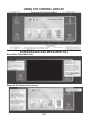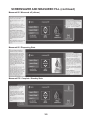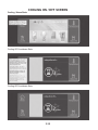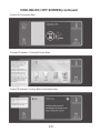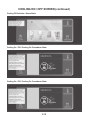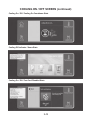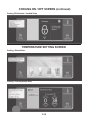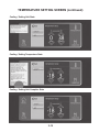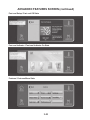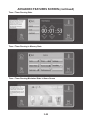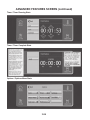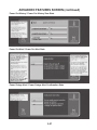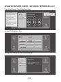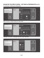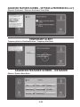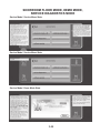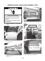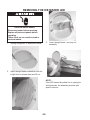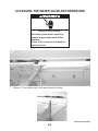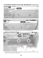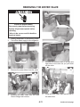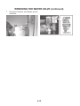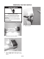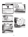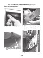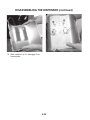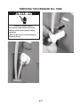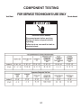
1
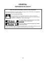
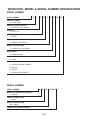
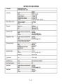
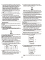
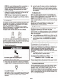
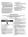
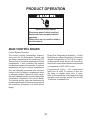
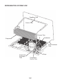
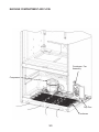
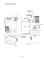
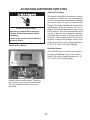
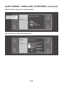
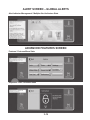
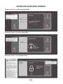
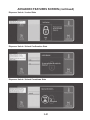
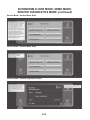
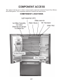
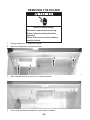
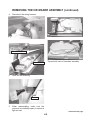
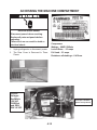
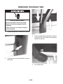
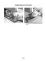
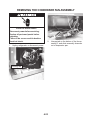
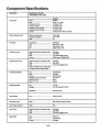
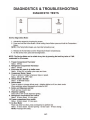
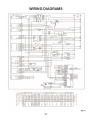
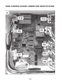
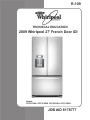
R-109
TECHNICAL EDUCATION
2009 Whirlpool 27' French Door IDI
Models KBFA20ER & KBFA25ER
Models:
GI7FVCXWA GI7FVCXWB GI7FVCXWQ GI7FVCXWY
JOB AID 8178777
FORWARD
This Job Aid, (Part No. 8178777), provides the technician with information on the installation,
operation, and service of the Whirlpool 27' French Door Bottom-Mount Refrigerator. For specific
information on the model being serviced, refer to the “Use and Care Guide,” or “Tech Sheet”
provided with the Whirlpool 27' French Door Bottom-Mount Refrigerator.
The Wiring Diagrams used in this Job Aid are typical and should be used for training purposes
only. Always use the Wiring Diagram supplied with the product when servicing the refrigerator.
GOALS AND OBJECTIVES
The goal of this Job Aid is to provide information that will enable the service technician to properly diagnose malfunctions and repair the Whirlpool 27' French Door Bottom-Mount Refrigerator.
The objectives of this Job Aid are to:
• Understand and follow proper safety precautions.
• Successfully troubleshoot and diagnose malfunctions.
• Successfully perform necessary repairs.
• Successfully return the refrigerator to its proper operational status.
WHIRLPOOL CORPORATION assumes no responsibility for any repairs
made on our products by anyone other than Authorized Service Technicians.
Copyright © 2009, Whirlpool Corporation, Benton Harbor, MI 49022
- ii -
TABLE OF CONTENTS
Page
GENERAL . . . . . . . . . . . . . . . . . . . . . . . . . . . . . . . . . . . . . . . . . . . . . . . . . . . . . . . . . . . . . . . 1-1
Refrigerator Safety . . . . . . . . . . . . . . . . . . . . . . . . . . . . . . . . . . . . . . . . . . . . . . . . . . . . . . . 1-1
Whirlpool Model And Serial Number Designations. . . . . . . . . . . . . . . . . . . . . . . . . . . . . . . 1-2
Model And Serial Number Label And Tech Sheet Locations. . . . . . . . . . . . . . . . . . . . . . . . 1-3
Specifications . . . . . . . . . . . . . . . . . . . . . . . . . . . . . . . . . . . . . . . . . . . . . . . . . . . . . . . . . . . 1-4
Whirlpool Corporation Major Appliance Warranty. . . . . . . . . . . . . . . . . . . . . . . . . . . . . . . . 1-5
INSTALLATION REQUIREMENTS . . . . . . . . . . . . . . . . . . . . . . . . . . . . . . . . . . . . . . . . . . . . 2-1
Installation Instructions . . . . . . . . . . . . . . . . . . . . . . . . . . . . . . . . . . . . . . . . . . . . . . . . . . . . 2-1
PRODUCT OPERATION. . . . . . . . . . . . . . . . . . . . . . . . . . . . . . . . . . . . . . . . . . . . . . . . . . . . . 3-1
Main Control Board. . . . . . . . . . . . . . . . . . . . . . . . . . . . . . . . . . . . . . . . . . . . . . . . . . . . . . . 3-1
Refrigeration System Flow . . . . . . . . . . . . . . . . . . . . . . . . . . . . . . . . . . . . . . . . . . . . . . . . . 3-2
Machine Compartment Air Flow . . . . . . . . . . . . . . . . . . . . . . . . . . . . . . . . . . . . . . . . . . . . . 3-3
Cabinet Air Flow . . . . . . . . . . . . . . . . . . . . . . . . . . . . . . . . . . . . . . . . . . . . . . . . . . . . . . . . . 3-4
Cabinet Water Flow. . . . . . . . . . . . . . . . . . . . . . . . . . . . . . . . . . . . . . . . . . . . . . . . . . . . . . . 3-5
Ice Compartment And Freezer Fan Operation . . . . . . . . . . . . . . . . . . . . . . . . . . . . . . . . . . 3-6
Accessing Dispenser Switches. . . . . . . . . . . . . . . . . . . . . . . . . . . . . . . . . . . . . . . . . . . . . . 3-7
Using The Control Display. . . . . . . . . . . . . . . . . . . . . . . . . . . . . . . . . . . . . . . . . . . . . . . . . . 3-8
COMPONENT ACCESS. . . . . . . . . . . . . . . . . . . . . . . . . . . . . . . . . . . . . . . . . . . . . . . . . . . . . 4-1
Component Locations. . . . . . . . . . . . . . . . . . . . . . . . . . . . . . . . . . . . . . . . . . . . . . . . . . . . . 4-1
Removing The Facade . . . . . . . . . . . . . . . . . . . . . . . . . . . . . . . . . . . . . . . . . . . . . . . . . . . . 4-2
Removing The Ice Maker Assembly. . . . . . . . . . . . . . . . . . . . . . . . . . . . . . . . . . . . . . . . . . 4-4
Removing The Heat Shield And Thermal Fuse. . . . . . . . . . . . . . . . . . . . . . . . . . . . . . . . . . 4-7
Removing The Ice Maker LED . . . . . . . . . . . . . . . . . . . . . . . . . . . . . . . . . . . . . . . . . . . . . . 4-8
Accessing The Water Valve And Reservor. . . . . . . . . . . . . . . . . . . . . . . . . . . . . . . . . . . . . 4-9
Removing The Water Valve. . . . . . . . . . . . . . . . . . . . . . . . . . . . . . . . . . . . . . . . . . . . . . . . 4-11
Removing The Test Switch. . . . . . . . . . . . . . . . . . . . . . . . . . . . . . . . . . . . . . . . . . . . . . . . 4-13
Accessing The Motorized Air Damper. . . . . . . . . . . . . . . . . . . . . . . . . . . . . . . . . . . . . . . . 4-14
Accessing The Machine Compartment. . . . . . . . . . . . . . . . . . . . . . . . . . . . . . . . . . . . . . . 4-15
Removing The Compressor . . . . . . . . . . . . . . . . . . . . . . . . . . . . . . . . . . . . . . . . . . . . . . . 4-16
Accessing The Electronic Boards. . . . . . . . . . . . . . . . . . . . . . . . . . . . . . . . . . . . . . . . . . . 4-17
Removing The Drain Tube . . . . . . . . . . . . . . . . . . . . . . . . . . . . . . . . . . . . . . . . . . . . . . . . 4-18
Leveling Legs . . . . . . . . . . . . . . . . . . . . . . . . . . . . . . . . . . . . . . . . . . . . . . . . . . . . . . . . . . 4-19
Dropping The Machine Compartment Pan. . . . . . . . . . . . . . . . . . . . . . . . . . . . . . . . . . . . 4-20
Removing Left Roller. . . . . . . . . . . . . . . . . . . . . . . . . . . . . . . . . . . . . . . . . . . . . . . . . . . . . 4-21
Removing The Evaporation Pan. . . . . . . . . . . . . . . . . . . . . . . . . . . . . . . . . . . . . . . . . . . . 4-22
Removing The Condenser Fan Assembly. . . . . . . . . . . . . . . . . . . . . . . . . . . . . . . . . . . . . 4-23
Disassembling The Dispenser. . . . . . . . . . . . . . . . . . . . . . . . . . . . . . . . . . . . . . . . . . . . . . 4-24
Accessing The Door Hinges And Water Tubes. . . . . . . . . . . . . . . . . . . . . . . . . . . . . . . . . 4-29
Preparation For Left Door Removal . . . . . . . . . . . . . . . . . . . . . . . . . . . . . . . . . . . . . . . . . 4-30
Removing The Ice Maker Fill Tube. . . . . . . . . . . . . . . . . . . . . . . . . . . . . . . . . . . . . . . . . . 4-31
- iii -
TABLE OF CONTENTS (continued)
COMPONENT TESTING . . . . . . . . . . . . . . . . . . . . . . . . . . . . . . . . . . . . . . . . . . . . . . . . . . . .
For Service Technician's Use Only . . . . . . . . . . . . . . . . . . . . . . . . . . . . . . . . . . . . . . . . . . .
Component Specifications. . . . . . . . . . . . . . . . . . . . . . . . . . . . . . . . . . . . . . . . . . . . . . . . . .
DIAGNOSTICS AND TROUBLESHOOTING . . . . . . . . . . . . . . . . . . . . . . . . . . . . . . . . . . . .
Diagnostic Tests . . . . . . . . . . . . . . . . . . . . . . . . . . . . . . . . . . . . . . . . . . . . . . . . . . . . . . . . .
Troubleshooting. . . . . . . . . . . . . . . . . . . . . . . . . . . . . . . . . . . . . . . . . . . . . . . . . . . . . . . . . .
5-1
5-1
5-2
6-1
6-1
6-3
WIRING DIAGRAMS . . . . . . . . . . . . . . . . . . . . . . . . . . . . . . . . . . . . . . . . . . . . . . . . . . . . . . . 7-1
Main Control Board. . . . . . . . . . . . . . . . . . . . . . . . . . . . . . . . . . . . . . . . . . . . . . . . . . . . . . . 7-2
Main Control Board Connector Identification . . . . . . . . . . . . . . . . . . . . . . . . . . . . . . . . . . . 7-3
- iv -
GENERAL
REFRIGERATOR SAFETY
Your safety and the safety of others is very important.
We have provided many important safety messages in this Job Aid and on the appliance.
Always read and obey all safety messages.
This is the safety alert symbol.
This symbol alerts you to hazards that can kill or hurt you and others.
All safety messages will follow the safety alert symbol and either the word “DANGER” or “WARNING.” These words mean:
DANGER
You can be killed or seriously injured if you don’t
immediately follow instructions.
WARNING
You can be killed or seriously injured if you don’t
follow instructions.
All safety messages will tell you what the potential hazard is, tell you how to reduce the chance
of injury, and tell you what can happen if the instructions are not followed.
1-1
WHIRLPOOL MODEL & SERIAL NUMBER DESIGNATIONS
MODEL NUMBER
MODEL NUMBER
G
I
7
F
V
C
X
PRODUCT GROUP
G = WHIRLPOOL
PRODUCT IDENTIFICATION
I = EXTERNAL ICE & WATER
CAPACITY
7 = 27 CU. FT.
MODEL/SERIES
F = RETAIL
MODEL FEATURE VARIANTS
V = SPECIAL VARIATION
MODEL FEATURE CODE
C = IN DOOR ICE DISPENSER
DOOR SWING
X = FRENCH DOOR
YEAR OF INTRODUCTION
W = 2009
COLOR CODE
A = SATINA ON MONO CABINET
B = BLACK
Q = WHITE
Y = SS ON MONO CABINET
SERIAL NUMBER
SERIAL NUMBER
K
Y
16
MANUFACTURING RESPONSIBILITY
K = AMANA
YEAR OF PRODUCTION
Y = 2009
WEEK OF PRODUCTION
16th = WEEK
PRODUCT SEQUENCE NUMBER
1-2
12345
W
A
MODEL & SERIAL NUMBER
LABEL & TECH SHEET LOCATIONS
The Model & Serial Number label location is shown below.
Model & Serial Number Label
The Tech Sheet location is shown below.
Bottom Grille
Tech Sheet
1-3
SPECIFICATIONS
1-4
WHIRLPOOL CORPORATION MAJOR APPLIANCE WARRANTY
1-5
— NOTES —
1-6
INSTALLATION REQUIREMENTS
INSTALLATION INSTRUCTIONS
LOCATION REQUIREMENTS
ELECTRICAL REQUIREMENTS
2-1
WATER SUPPLY REQUIREMENTS
CONNECT THE WATER SUPPLY
2-2
REFRIGERATOR DOORS AND DRAWER
2-3
2-4
Electrical Shock Hazard
Disconnect power before removing doors.
Failure to do so can result in death or electrical shock.
2-5
REFRIGERATOR USE
OPENING AND CLOSING DOORS
2-6
CRISPER HUMIDITY CONTROL
WATER AND ICE DISPENSER
(on some models)
2-7
2-8
ICE MAKER AND STORAGE BIN
2-9
WATER FILTRATION SYSTEM
REFRIGERATOR CARE
CLEANING
2-10
CHANGING THE LIGHT BULB
TROUBLESHOOTING
REFRIGERATOR OPERATION
2-11
ICE AND WATER
TEMPERATURE AND MOISTURE
2-12
2-13
— NOTES —
2-14
PRODUCT OPERATION
Electrical Shock Hazard
Disconnect power before servicing.
Replace all parts and panels before
operating.
Failure to do so can result in death or
electrical shock.
MAIN CONTROL BOARD
Control System Overview:
The control provides independent temperature control for the Refrigerator, Freezer and
Ice Maker compartments by monitoring NTC
Thermistors for the actual temperature of each
compartment. It also considers the ambient
temperature measured by a sensor. It receives
temperature set points of each compartment
from an externally connected user interface,
except for the Ice Maker compartment which
is internally defined. Based on these inputs,
the control determines the required state of the
Compressor, Evaporator Fan and Air Baffle.
The optimal defrost times are determined by
monitoring the length of time required to defrost
the evaporator compared to an ideal defrost
length.
Board Over Temperature Operation – Control
Board has an onboard thermistor. If thermistor
detects a temperature of 75 C/167F or higher,
all thermostatic loads will turn off. Normal operation will resume when the thermistor senses
a temperature of 60C/140F or less.
Compartment Lights – All compartment
lights turn off after 10 minutes of door being open, no matter which door is open.
Note: In Service Mode, in the diagnostic steps
the lights work normally and will turn off after
10 minutes of elapsed time.
3-1
REFRIGERATION SYSTEM FLOW
Cappillary Tube
Suction Tube
Process Tube
Condenser
Evaporator
Post Condenser
Tube
Compressor
Discharge
Tube
Dryer
Compressor
Suction Tube
3-2
MACHINE COMPARTMENT AIR FLOW
Condenser Fan
Assembly
Compressor
Drip Pan
Condenser
3-3
CABINET AIR FLOW
Ice Bin Air
Return
Refrigerator
Return Air
Tunnel
Refrigerator
Return Air
Tunnel
Freezer Air
Supply Grille
Freezer Return Air
Through Louvers At
Bottom Of Evaporator
3-4
CABINET WATER FLOW
1/4" O.D.
Plastic Tubing
Foamed-in
Conduit
5/16" O.D.
Plastic Tubing
Water Valve
Foamed-in
Conduit
5/16" O.D.
Plastic Tubing
Dispenser
Ice Maker
Fill Tube
Water Filter
1/4" O.D.
Plastic Tubing
5/16" O.D.
Plastic Tubing
Water Tank
Foamed-in
Conduit
Incoming Water Line Connection For
1/4" O.D. Copper tube Compression
Fitting
3-5
ICE COMPARTMENT AND FREEZER FAN OPERATION
Ice Compartment and Freezer Fan Operation
Freezer Compartment Calling For Cooling - Evaporator Fan On 100%, Compressor Speed Varies
Depending On the Freezer Temperature
Refrigerator Compartment Calling For Cooling - Damper Open, IC Fan On 30%, And Evaporator
Fan On 100%
RC Calling for Cooling and Ice Maker in Freeze Cycle - Damper Open, IC Fan On 55%, And
Evaporator Fan On 100%
RC Satisfied and Ice Maker in Freezing Mode - Damper Closed, IC Fan On 55%, And Evaporator Fan On 100%
Ice Maker Harvesting - Damper Open, IC Fan Off, and Evaporator Fan On 100%
Ice Bin Melting 30 degrees or ^ - Damper Closed, IC Fan On 90% And Evaporator Fan On
100%
Defrost Cycle - Damper Closed, IC Fan Off, And Evaporator Fan Off
3-6
ACCESSING DISPENSER SWITCHES
Ambient Thermistor
The ambient thermistor information is used in
an equation to adjust the control temperature
values. As the ambient temperature changes
the control value will shift to correct for the
change. This helps maintain the compartment
temperatures at the set value on the user interface. The ambient temperature may or may
not be used for all of the compartments but it
can be. It depends on a regression equation
calculated from results of testing performed
in the lab. The Humidity sensor is used in an
equation to adjust the Wattage output of the
mullion heater. The mullion heater operates at
0, 30, 70 or 100% of its rated Wattage
Electrical Shock Hazard
Disconnect power before servicing.
Replace all parts and panels before
operating.
Failure to do so can result in death or
electrical shock.
User Interface Board
Humidity Sensor
The Humidity sensor is used in an equation
to adjust the Wattage output of the mullion
heater. The mullion heater operates at 0, 30,
70 or 100% of it's rated Wattage.
Humidity Sensor and Ambient Thermistor
are Located on the User Interface Board.
The user interface board is sold as an
assembly.
3-7
USING THE CONTROL DISPLAY
Overview of UI (home state)
SCREENSAVER AND MEASURED FILL
Sleep Mode / Sleep Mode State
Measured fill / Measured off (=Home)
3-8
SCREENSAVER AND MEASURED FILL (continued)
Measured fill / Measured off (=Home)
Measured fill / Dispensing State
Measured Fill / Complete / Standby State
3-9
Cooling / Home State
COOLING ON / OFF SCREEN
Cooling Off Countdown State
Cooling Off Countdown State
3-10
COOLING ON / OFF SCREEN (continued)
Cooling Off Countdown State
Cooling Off Indicator / Cooling Off Active State
Cooling Off Indicator / Cooling Status Information State
3-11
COOLING ON / OFF SCREEN (continued)
Cooling Off Indicator / Home State
Cooling On / Off / Cooling On Countdown State
Cooling On / Off / Cooling On Countdown State
3-12
COOLING ON / OFF SCREEN (continued)
Cooling On / Off / Cooling On Countdown State
Cooling Off Indicator / Home State
Cooling On / Off / Fast Cool Disabled State
3-13
COOLING ON / OFF SCREEN (continued)
Cooling Off Indicator / Locked State
TEMPERATURE SETTING SCREEN
Cooling / Home State
Cooling / Cooling Setup State
3-14
TEMPERATURE SETTING SCREEN (continued)
Cooling / Setting Unit State
Cooling / Setting Temperature State
Cooling / Setting Unit Complete State
3-15
ALERT SCREEN – DOOR AJAR, FILTER RESET
Door Alarm Indicator / Door Alarm Active State
Door Alarm Indicator / Door Alarm Alert Screen State
Door Alarm Indicator / Door Alarm Snooze State (=Active State)
3-16
ALERT SCREEN – DOOR AJAR, FILTER RESET (continued)
Water Filter Indicator / Water Filter Order State
Water Filter Status / Water Filter Setup State
Water Filter Alert / Water Filter Confirmation State
3-17
ALERT SCREEN – DOOR AJAR, FILTER RESET (continued)
Water Filter Alert / Water Filter Countdown State
Water Filter Status / Water Filter Setup State
3-18
ALERT SCREEN – GLOBAL ALERTS
Alert Indicator Management / Multiple Alert Indicators State
ADVANCED FEATURES SCREEN
Features / Features Menu State
Dispenser Lock / Unlocked State
3-19
ADVANCED FEATURES SCREEN
Dispenser Lock / Lock Confirmation State
Dispenser Lock / Lock Countdown State
Dispenser Lock / Lock Complete State
3-20
ADVANCED FEATURES SCREEN (continued)
Dispenser Unlock / Locked State
Dispenser Unlock / Unlock Confirmation State
Dispenser Unlock / Unlock Countdown State
3-21
ADVANCED FEATURES SCREEN (continued)
Dispenser Unlock / Unlock Complete State
Features / Features Menu State
Fast cool Setup / Fast cool Off State
3-22
ADVANCED FEATURES SCREEN (continued)
Fast cool Setup / Fast cool Off State
Fast cool Indicator / Fast cool Indicator On State
Features / Features Menu State
3-23
ADVANCED FEATURES SCREEN (continued)
Timer / Timer Setup State
Timer / Timer Running State
Timer / Timer Running Maximized State
3-24
ADVANCED FEATURES SCREEN (continued)
Timer / Timer Running State
Timer / Timer Running in Memory State
Timer / Timer Running Minimized State in Home Screen
3-25
ADVANCED FEATURES SCREEN (continued)
Timer / Timer Running State
Timer / Timer Complete State
Options / Options Menu State
3-26
ADVANCED FEATURES SCREEN (continued)
Power Out History / Power Out History View State
Power Out Alert / Power Out Alert State
Power Outage Alert / Power Outage Alert Confirmation State
3-27
ADVANCED FEATURES SCREEN (continued)
Power Out Alert / Power Out Alert Countdown State
ADVANCED FEATURES SCREEN – SETTINGS & PREFERENCES
Home State
Options / Options Menu State
3-28
ADVANCED FEATURES SCREEN – SETTINGS & PREFERENCES (con't)
Brightness Setting / Brightness Setup State
Volume Setting / Volume Setup State
Time & Date Setting / Time & Date Setup State
3-29
ADVANCED FEATURES SCREEN – SETTINGS & PREFERENCES (con't)
Time & Date Setting / Time & Date Setup State
Settings / Settings Menu State
Factory reset Setting / Factory reset Setup State
3-30
ADVANCED FEATURES SCREEN – SETTINGS & PREFERENCES (con't)
Factory reset Setting / Factory reset Setup State
Features / Features Menu State
Preferences / Preferences Menu State
3-31
ADVANCED FEATURES SCREEN – SETTINGS & PREFERENCES (con't)
Ice Preference / Ice Preference Setup State
Water Preference / Water Preference Setup State
Language Preference / Language Preference Setup StateState
3-32
ADVANCED FEATURES SCREEN – SETTINGS & PREFERENCES (con't)
Dispense Preference / Dispense Preference Setup State
TEMPORARY ALERT
Temporary Alert for Disabled Buttons / Temporary Alert State
ADVANCED FEATURES SCREEN – ICE MAKER
Options / Options Menu State
3-33
ADVANCED FEATURES SCREEN – ICE MAKER (continued)
Ice maker Setting / Ice maker Setup State
Ice maker Setting / Ice maker Setup State
3-34
SHOWROOM FLOOR MODE, DEMO MODE,
SERVICE DIAGNOSTICS MODE
Service Mode / Service Menu State
Service Mode / Service Menu State
Service Mode / Demo Mode State
3-35
SHOWROOM FLOOR MODE, DEMO MODE,
SERVICE DIAGNOSTICS MODE (continued)
Service Mode / Service Menu State
Service Mode / Service Menu State
Service Mode / Service Diagnostics State
3-36
SHOWROOM FLOOR MODE, DEMO MODE,
SERVICE DIAGNOSTICS MODE (continued)
Service Mode / Service Diagnostics State
Service Mode / Service Diagnostics State
Service Mode / Service Menu State
3-37
– NOTES –
3-38
COMPONENT ACCESS
This section instructs you on how to service each component inside the French Door BottomMount Refrigerator. The components and their locations are shown below.
COMPONENT LOCATIONS
4-1
REMOVING THE FACADE
Electrical Shock Hazard
Disconnect power before servicing.
Replace all parts and panels before
operating.
Failure to do so can result in death or
electrical shock.
1. Unplug refrigerator or disconnect power.
2. Open the refrigerator compartment door.
3. Tape indicates where to insert tool to release facade.
4. Use a wide flat blade screwdriver or putty knife to release
4-2
REMOVING THE FACADE (continued)
Front Tabs
Rear Tabs
4-3
REMOVING THE ICE MAKER ASSEMBLY
Electrical Shock Hazard
Disconnect power before servicing.
Replace all parts and panels before
operating.
Failure to do so can result in death or
electrical shock.
1. Remove the ¼” hex head screw securing
the ice maker assembly to the cabinet.
3. Rest the assembly on the upper shelf
2. Pull the ice maker assembly out and down
to remove.
4-4
REMOVING THE ICE MAKER ASSEMBLY (continued)
4. Disconnect the wiring harness.
.
Critical Sealing Areas
Top and side view of icemaker assembly.
Foam Air Seal
5. Slide out the assembly.
Grommet
6. When reassembling, make sure the
grommet is installed properly to ensure a
tight air seal.
4-5
Continued next page.
REMOVING THE ICE MAKER ASSEMBLY (continued)
Lip of Ice Maker Air Diffuser Slips
into Channel in Housing
Insert Screw Driver Blade
and Twist
7. Unsnap fasteners securing fan cover and lift
off.
9. Remove the icemaker cover.
Test Switch
8. Roll out the ice maker to disengage lip on
air diverter from ice maker housing and remove
4-6
REMOVING HEAT SHIELD AND THERMAL FUSE
Electrical Shock Hazard
Disconnect power before servicing.
Replace all parts and panels before
operating.
Failure to do so can result in death or
electrical shock.
View of the bottom of the new small cube ice
maker.
1. Unplug refrigerator or disconnect
power.
Depress Locking Tab
and Remove Harness
2. Remove 3 screws securing air difffuser to
ice maker mold.
6 cavity Small cube ice maker core.
3. Unclip the thermal fuse from the ice
maker mold.
4-7
REMOVING THE ICE MAKER LED
Electrical Shock Hazard
Disconnect power before servicing.
Replace all parts and panels before
operating.
Failure to do so can result in death or
electrical shock.
3. Insert straight blade and pop out
assembly.
1. Unplug refrigerator or disconnect power.
2. Insert straight blade screwdriver into slot
in light lens to release tabs and lift out.
NOTE:
If the LED cannot be pulled out to unplug the
wiring harness, the assembly must be split
apart to remove.
4-8
ACCESSING THE WATER VALVE AND RESERVOIR
Electrical Shock Hazard
Disconnect power before servicing.
Replace all parts and panels before
operating.
Failure to do so can result in death or
electrical shock.
1. Remove ¼” hex head screw on left and right side of cover.
4-9
Continued next page.
ACCESSING WATER VALVE AND RESERVOIR (continued)
Release Clip
Release Clip
2. Release the clips on left and right side of the cover as it is pulled downward.
3. Drop the front of the cover and slide cover back. There are two tabs on the rear of the cover
that fit into slots in the rear of the cavity..
4-10
REMOVING THE WATER VALVE
Electrical Shock Hazard
Disconnect power before servicing.
Replace all parts and panels before
operating.
Failure to do so can result in death or
electrical shock.
1. Unplug refrigerator or disconnect power.
2. Turn off the water supply to the refrigerator.
5. Release the retainer tabs on the left and
right side of the valve as you pull down
on the valve.
3. Remove the water tubes from the valve
4. Release the water tubes from the John
Guess fittings and remove.
6. Drop the valve down and remove the inlet water tube.
4-11
Continued next page.
REMOVING THE WATER VALVE (continued)
7. Disconnect harness and chassis ground
connector .
4-12
REMOVING THE TEST SWITCH
Electrical Shock Hazard
Disconnect power before servicing.
Replace all parts and panels before
operating.
Failure to do so can result in death or
electrical shock.
3. Remove switch.
1. Disconnect wires from switch.
2. Use a straight blade screw driver to release locking tab on the side of the
switch.
4-13
ACCESSING THE MOTORIZED AIR DAMPER
Electrical Shock Hazard
Disconnect power before servicing.
Replace all parts and panels before
operating.
Failure to do so can result in death or
electrical shock.
1. Unplug refrigerator or disconnect power.
2. Lift motorized damper from the housing.
View of damper door.
4-14
ACCESSING THE MACHINE COMPARTMENT
Electrical Shock Hazard
Disconnect power before servicing.
Replace all parts and panels before
operating.
Failure to do so can result in death or
electrical shock.
1. Unplug refrigerator or disconnect power.
2. The Rear Cover Is Removed In Three
Pieces
Compressor:
Wattage – 60HZ/113Watts
Locked Rotor – 3.3 amps
Full Load – 3.3 amps
Resistance all windings – 6.4 Ohms
Inverter
Voltages:
Red/White
120 VAC
ORG/Red
and ORG/
WH 3-6 VDC
Embraco variable
speed compressor
4-15
REMOVING THE COMPRESSOR
Electrical Shock Hazard
Disconnect power before servicing.
Replace all parts and panels before
operating.
Failure to do so can result in death or
electrical shock.
1. Unplug refrigerator or disconnect power.
3. Straighten locking tab
2. Turn counterclockwise
4. Lift off dog bone
4-16
ACCESSING THE ELECTRONIC BOARDS
Electrical Shock Hazard
Disconnect power before servicing.
Replace all parts and panels before
operating.
Failure to do so can result in death or
electrical shock.
Main Control Board
1. Unplug refrigerator or disconnect power.
2. Remove 4 screws securing cover.
3. Unsnap and remove plastic cover.
4-17
New Power Supply Board
REMOVING THE DRAIN TUBE
Electrical Shock Hazard
Disconnect power before servicing.
Replace all parts and panels before
operating.
Failure to do so can result in death or
electrical shock.
1. Unplug refrigerator or disconnect power.
3. Insert a straight blade screwdriver vertically from the top of the drain tube opening to
release locking tab.
2. A locking tab must be released to remove
drain tube.
4. Lift off drain tube.
4-18
LEVELING LEGS
Front roller adjustment 3/8” Hex Head Bolt Clockwise raises cabinet Counterclockwise lowers
cabinet.
After leveling unit, adjust brake so rubber foot contacts floor.
4-19
DROPPING THE MACHINE COMPARTMENT PAN
Electrical Shock Hazard
Disconnect power before servicing.
Replace all parts and panels before
operating.
Failure to do so can result in death or
electrical shock.
1. Unplug refrigerator or disconnect power.
2. Tilt condenser fan side of cabinet
2. Remove the 2 Torx screws securing the
base pan to the cabinet and drop the
down the base pan
4-20
REMOVING LEFT ROLLER
1. Slide pin out of bracket and remove the
roller.
4-21
REMOVING THE EVAPORATION PAN
Electrical Shock Hazard
Disconnect power before servicing.
Replace all parts and panels before
operating.
Failure to do so can result in death or
electrical shock.
4. Release the 2 evaporation pan tabs inserted into the cabinet
1. Unplug refrigerator or disconnect power.
2. Lift the condenser line out of the evaporation pan bracket
5. Tabs on the evaporation pan secure the
front of the pan to the base.
3. Release the 2 evaporation pan tabs inserted into the cabinet
4-22
REMOVING THE CONDENSER FAN ASSEMBLY
Electrical Shock Hazard
Disconnect power before servicing.
Replace all parts and panels before
operating.
Failure to do so can result in death or
electrical shock.
1. Unplug refrigerator or disconnect power.
2. Unsnap tab on the bottom of the fan assembly 2 and slide assembly channels
out of evaporator pan.
Locking Tab
4-23
DISASSEMBLING THE DISPENSER
Electrical Shock Hazard
Disconnect power before servicing.
Replace all parts and panels before
operating.
Failure to do so can result in death or
electrical shock.
1. Unplug refrigerator or disconnect power.
2. Remove drip pan and tray.
4-24
DISASSEMBLING THE DISPENSER (continued)
Remove the User Interface Board
3. Remove the User Interface Board
.
4
5. Pull out on the bottom of the user interface board as you pull down. Tabs on the
top of the user interface engage slots in
the dispenser housing.
Release the clips on the left and right
side on the bottom of the user interface
board
6. Disconnect wire harnesses.
4-25
Continued next page.
DISASSEMBLING THE DISPENSER (continued)
7. Unsnap water tube from divider.
10. Remove the divider.
8. Remove the two 1/4” hex head screws.
11. Disconnect the wiring harnesses.
9. Release the clips on the left and right
side of the dispenser divider.
4-26
DISASSEMBLING THE DISPENSER (continued)
12. Remove the two 1/4” hex head screws securing the lower pan to the housing.
13. Remove the pan.
15. Disengage the facade tabs from the slots
in the housing.
14. Depress the rear of the dispenser facade
and and lift.
4-27
Continued next page.
DISASSEMBLING THE DISPENSER (continued)
16. Slide switches up to disengage from
housing tabs.
4-28
ACCESSING THE DOOR HINGES AND WATER TUBES
Electrical Shock Hazard
Disconnect power before servicing.
Replace all parts and panels before
operating.
Failure to do so can result in death or
electrical shock.
Figure 3
3. Remove the Phillips head screw securing the “T” shaped cover to the top of the
cabinet, see figure 4.
1. Unplug refrigerator or disconnect power.
Figure 1
Figure 4
4. Remove the cover to expose the water
tubes and wiring harness, see figure 5.
Figure 2
2. Remove the right and left hand hinge
cover, see figures 1,2 and 3.
Figure 5
4-29
PREPARATION FOR LEFT DOOR REMOVAL
Electrical Shock Hazard
Disconnect power before servicing.
Replace all parts and panels before
operating.
Failure to do so can result in death or
electrical shock.
1. Unplug refrigerator or disconnect power.
2. Disconnect John Guess Fitting, see figure 1.
3. Unplug Wire Harness, see figure 2.
Figure 2
Figure 1
4-30
REMOVING THE ICEMAKER FILL TUBE
Electrical Shock Hazard
Disconnect power before servicing.
Replace all parts and panels before
operating.
Failure to do so can result in death or
electrical shock.
4-31
– NOTES –
4-32
COMPONENT TESTING
Electrical Shock Hazard
Disconnect power before servicing.
Replace all parts and panels before
operating.
Failure to do so can result in death or
electrical shock.
5-1
5-2
DIAGNOSTICS & TROUBLESHOOTING
DIAGNOSTIC TESTS
6-1
DIAGNOSTIC TESTS (continued)
6-2
WIRING DIAGRAMS
7-1
MAIN CONTROL BOARD CONNECTOR IDENTIFICATION
7-2
PRODUCT SPECIFICATIONS
AND
WARRANTY INFORMATION SOURCES
IN THE UNITED STATES:
FOR PRODUCT SPECIFICATIONS AND WARANTY INFORMATION CALL:
FOR WHIRLPOOL PRODUCTS: 1-800-253-1301
FOR KITCHENAID PRODUCTS: 1-800-422-1230
FOR ROPER PRODUCTS: 1-800-447-6737
FOR TECHNICAL ASSISTANCE WHILE AT THE CUSTOMER’S HOME CALL:
THE TECHNICAL ASSISTANCE LINE: 1-800-253-2870
HAVE YOUR STORE NUMBER READY TO IDENTIFY YOU AS AN
AUTHORIZED SERVICER
FOR LITERATURE ORDERS:
PHONE: 1-800-851-4605
FOR TECHNICAL INFORMATION AND SERVICE POINTERS:
www.servicematters.com
IN CANADA:
FOR PRODUCT SPECIFICATIONS AND WARRANTY INFORMATION CALL:
1-800-461-5681
FOR TECHNICAL ASSISTANCE WHILE AT THE CUSTOMER’S HOME CALL:
THE TECHNICAL ASSISTANCE LINE: 1-800-488-4791
HAVE YOUR STORE NUMBER READY TO IDENTIFY YOU AS AN
AUTHORIZED SERVICER