1
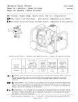
SEARS
OWNER'S
MANUAL
MODEL NO.
390.252158
CRAFTSMAN °
CAUTION:
Read and Follow
All Safety Rulesand
Operating Instructions
Before FirstUse of
ThisProduct.
Save This Manual For
Future Reference.
PROFESSIONAL
112 HP SHALLOW WELL
WATER SYSTEM
• Safety Instructions
• Installation
• Electrical
• Maintenance
• Repair Parts
Sears, Roebuck and Co., Hoffman
PRINTED
IN
U.S.A.
Estates, IL 60179
U.S.A.
Form No.
F642-9823
(9/2S/98)
CONTENTS
INTRODUCTION/WARRANTY
INTRODUCTION
..........................................
2
PUMP PERFORMANCE .......................................................
3
MAJOR COMPONENTS
......................................................
INSTALLATION ................................................................
3
4-5
ELECTRICAL .....................................................................
5_6
OPERATION
........................................................................
MAINTENANCE
7
...............................................................
7-9
HELPFUL HINTS ...............................................................
10
TROUBLESHOOTING
11
GUIDE ...........................................
REPAIR PARTS .............................................................
FULL
ONE YEAR
For one year from the date Of purchase,
LIMITED
WARRANTY
ON
ON
CRAFTSMAN*
This x,_arTanty does not cover repairs or replacement
according
to the instructions
in the owners manual
replace
ff deft:cOve
PROFESSIONAL
Sears will fumL_,
FIVE YEAR WARRANTY
date of purch___e, Sears will repair-or
CRAFTSMAN*
well pump, free of charge,
three years from the date of purchase,
FULL
For rive years from
12-14
Sears will repair or replace
WARRANTY
After one year and through
Please read our instructions
before installing and using your
shallow Well Water System. This will help you obtain the
full benefits of the quality and convenience
built into this
equipment.
It will also help you avoid any needless service
expense resulting from causes beyond our control which are
not _:overed by our warranty.
states do not allow the exclusion
his
SERVICE
LS"A VAILABLE
or limitation
BY SIMPLY
wan'anty applies only while this product
of incidental
or consequential
CONTACTING
inclttding
PUMP
part. You pay labor.
AIR TANK
or workmanship.
faiinre
to install, adjust and operate
this pump
OF LIABILITY
SEARS WILL NOT BE LIABLE FOR LOSS OR DAMAGE TO PROPERTY
OR ANY INCIDENTAL
D_LIIAGE DUE DIRECTLY OR INDIRECTLY FROM THE USE OF THIS PRODUCT.
WARRANTY
in material
° WELL
part for any d_fective
_ CAPTIVE
if defective
becaus¢_ of abuse or negligence,
LIMITATION
Some
a replacement
ON CRAFTSMAN
parts necessary
PUMP
or workmanship.
HYDRO-GLASS
free of charge,
the tank, free of chaPge,
WELL
in material
THE NEAREST
damages,
OR CONSEQUENTIAL
LOSS OR EXPENSE
so the above limitation or exclusion
SEARS SERVICE
CENTER/DEPARTMENT
FROM PROPERTY
may not apply to you.
IN THE UNITED STA TEX
is in the Unite,J States.
This warranty gives you specific legal rights, and you may also have other rights which ,ra_ from state to state.
Sears, Roebuck and Co., Dept. 817WA, Hoffman Estates, IL 60179
READ AND
Carefully
read and follow
manual
or on pump.
FOLLOW
all safety
instructions
SAFETY
in this
,_
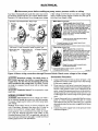
This is the safety alert symbol.
When you see this
symbol on your pump or in this manual, look for one
of the following signal words and be alert to the potential
for personal injury!
warns
personal
injury,
death
about
hazards
that wiil
or major property
cause
damage
F[_, CAUTION]7Motor normally operates
at high temperature
and will be too hot to touch. It is protected
from heat damage during operation
by an automatic internal cutoffswitch.
Before handling
pump or motor, stop motor and allow to
cool for 20 minutes.
1.
serious
if ignored.
2.
[_WARNING ]w ares abou t hazard stha t will or ca n cause serious personal
nored.
injury,
& CAUTION ]warns
minor
personal
The word
important
]
injury
death
about
or major property
hazards
or property
that will
damage
damage
or can
.
rtm-pump
cause
if ignored.
NOTICE indicates special instructions
but not related to hazards.
CAUTION ] Never
if ig-
dry. Running
which
pi_np
are
¢
without
water may cause pump to overheat,
damaging seal and possibly causing burns to persons
handling
pump. Fill pump
with water before starting.
[AWARNING]Never
run pump
against
closed
discharge.
To do so can boll water inside pump, causing hazardous
pressure
in unit, risk of explosion
and possibly
scalding
persons
handling
pump.
INSTRUCTIONS!
To avoid risk of serious bodily injury and property damage, read safety instructions
carefnily before installing
pump.
Follow local and/or
national plumbing
and electrical
codes when installing pump,
3.
Keep well covered while installing
pump to prevent
leaves and other debris from falling into well, contaminating well and possibly damaging pump.
4.
Protect pump and piping system from freezing. Allowing
pump or water system to freeze could severely damage
pump and voids warranty.
LAWARNINGJTo avoid
serious
injury'and
equipment damage, limit system pressure
to 100 pounds
per square
inch (PSI) or below
at all times. Overpressure
can cause tank blowup;
install relief valve
capable
of passing
full pump volume
at 100 PSI.
5. With a new well, test well for purity before
local Health Department
for procedure.
[AWARNING] Haz._u'dous voltage,
cause death, or start fires.
Can
use. Consult
shock,
burn,
SAFETY INSTRUCTIONS
6. Disconnect
electrical
working on pump.
power
source
before
installing
8. Line voltage and frequency
of electrical power supply
must agree with motor nameplate.
9. Use of fuses or wire smaller than size recommended
in
owner's
manual can cause overheating,
possible fires,
and will void warranty.
or
7. Ground pump with a ground wire run from grounding
lug on motor to a grounded
lead in the service panel.
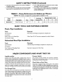
TABLE
I - Pump Performance
NOTE:
Pump
Model
(In Gallons per Minute)
This system is designed for pumping depths of 20 feet or less.
Description
390.252158
(Continued)
112 HP S.W. Jet
BASIC
TOOLS
Suct.
Disch.
Discharge
Pressure PSI
1-1/4"
1"
40
AND
MATERIALS
Pumping Depth in Feet
5'
10'
15'
20'
8.2
7.3
6.2
5.0
NEEDED
Plastic Pipe Installation
Tools
Materials
Pipe Wrenches
Plastic Pipe and Fittings (as required to complete job).
Screwdriver
Knife or Saw to Cut Plastic
Tire Pressure
Teflon
Pipe
Tape
(DO NOT use joint compound
on plastic
fittings).
Gauge
Galvanized
Steel Pipe Installation
Tools
Materials
Pipe Wrenches
Galvanized
Pipe and Fittings (as required
to complete
job).
Screwdriver
Pipe Cutting
and Threading
Tire Pressure
Tools
Compound
or Teflon Tape
Gauge
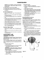
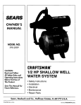
MAJOR
Impeller
Pipe Joint
COMPONENTS
AND
WHAT
Pressure
and Jet
THEY
DO
Switch
Impeller turns with motor shaft, causing water to fly out
from its rim by centrifugal
force. Impeller rotation creates a
vacuum which pulls in more water. Part of the water is diverted back to the jet where it passes through the nozzle and
venturi. This creates more vacuum to draw in more water.
The pressure
switch
provides
for automatic
operation.
Pump starts when pressnre
drops to 40 pounds and stops
when pressure reaches 60 pounds.
In shallow wells (less than 20 feet deep), the vacuum created at the pump is_enough
to pull water to toe pump.
Therefore,
for shallow _-ell use the jet is built into the pump.
This pump is equipped
with a built-in check valve. Install a
check valve as close to well as possible
o_ well point installations. A foot valve must be installed in the well on dug
or cased wells. See Figures ZA and 2B, Page 4. For long horizontal pipe runs, install check valve as close to well as possible (all types of wells).
Pre-Charged
Check
Tank
The tank serves two functions,
it provides
a reservoir
of
water under pressure
and maintains
a cushion
of air pressure to prevent
pipe hammering
and possible
damage to
plumbing
components.
When water is drawn off through
the house fixtures, the pressure
in the tank is lowered and
the pump starts.
3
Valve or Foot Valve
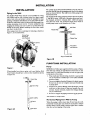
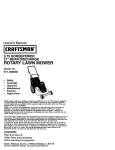
INSTALLATION
INSTALLATION
For a pump at sea level mounted
directly over the well, be
sure the total lift from the pumping water level to the pump
does not exceed 20 feet. This will be less ff the pump is offset from the well.
Piping in the Well
The Shallow Well Water System can be installed on a dug
well, drilled well or with a driven point. In a dug or cased
well, a foot valve and strainer
should be installed for easy
priming. It should be installed five to ten feet below the lowest level to which the water will drop while the pump is operating
(pumping
water
level). To keep sediment
from
clogging the strainer, be sure it is five to ten feet above the
bottom
of the well. Before installing
the foot valve, make
sure that it works freely.
When using a foot valve, a priming
Figure l, are recommended.
tee and plug as shown
The maximum lift of any pump decreases at the rate of about
1" less lift for every 1,000 feet of elevation above sea level.
For example,
at Denver, Colorado (Elev. 5,000') the pump
loses five feet of lift. The maximum
depth from which it
would pump water would therefore
be 15 feet.
Well Seal
Plastic Pilse
in
PrimingPlug,
Priming Tee
(User Supplied)
\
Pipe "
From
Well
and Strainer
5111293
Dug or Cased Well
Figure 2B
PUMP/TANK
INSTALLATION
Pump
Figure
I
When installed on a driven point well, your Shallow Well
Water System should have a check valve installed as shown
in Figure 2A.
NOTICE: Use Teflon tape supplied with the pump or PlastoJoint Stik' for making
all pipe-thread
connections
to the
pump itself. To avoid stress-cracking,
do not use pipe joint
compot_nds
on the pump.
1. Wrap male pipe threads being attached
to pump with
one or two layers of Teflon tape. Cover entire threaded
portion of pipe.
[_eck
Valve
2. Do not overtighten
threaded fittings in the plastic pump.
Be sure you do not try to tighten joint past thread stop
in pump port!
3. If leaks occur, remove fittings, clean offold tape, rewrap
with two to three layers of tape and remake the connection.
If joint still leaks, replace the fittings (fittings
may be undersized).
I
Steel Drive Pipe
4. Be sure to support
_Lake Chemical
Drive coupling
Well
Liven
Figure 2A
point
poi!It
Horizontal
Co., Chicago,
all piping
corlnected
to.,,th.€ System.
Illinois
Piping from
Well
to Pump
When the pump is offset more than 25 feet from the well,
horizontal
suction pipe size should be increased
to reduce
friction losses. Never install a suction pipe that is smaller
than the suction tapping of the pump.
INSTALLATION
1-1/4"
1-1/2"
2"
Up to 25 Ft.
25 to 50 Ft.
50 to 200 Ft.
quired on new installations,
pumps
pumps that have been disassembled
fonows:
1. Open
erate.
Discharge
When the pump is some distance from the house or point
of water use, the discharge pipe size should be increased to
reduce pressure losses caused by friction.
1-114"
1-1/2"
Up to 25 Ft.
25 to 100 Ft.
100 to 800 Ft.
furthest
from tank and allow pump
3. Open and close faucets
air has been removed.
repeatedly
until you are sure all
4. If stream does not become steady, air may be leaking into
the system; check for leaks in the piping on the suction
side of the pump.
NOTICE:
annually.
To prevent
waterlogging,
check
Tank
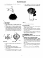
To Check Tank Air Charge
Tanks are pre-charged
with 40 PSI air pressure at the factory.
Your tank requires
an air ch.arge of 40 pounds per square
inch (PSI) for proper
operation;
check tank pressure
with
tire gauge to determine
flair charge needs adjustment.
Tank
pre-charge
should be checked
annually; see instructions
at
right.
If drawdown
(amount
of water available
creases significantly,
check as follows:
1
2
- air expands
Water begins to enter tank - air is compressed
separator as it fills with water.
3.
Pump-up
cycle
completed
- air now
4
cut off setting
4.
Water
forces
5.
Separator
begin.
above
compressed
to
4. Use soap or liquid detergent to check for air leaks around
air valve. Continuous
bubbling indicates a leak. If necessary, install new core in air valve. This is the same as
those used for automobile
tubeless tires.
area above
2.
de-
3. If the air pressure
is below 40 PSI, add air to the tank.
Use an air compressor
or a portable air storage tank.
3
filling
per cycle),
2. At the air valve in top of tank, check air pressure with
standard tire gauge. Air pressure should be the same as
pump pressure switch cut-in setting (40 PSI).
It is necessary
to flush all air out of the piping system and
water reservoir
portion of the pre-charged
tank. This is re-
Tank nearly empty
vinyl separator.
tank air charge
1. To check air charge in tank, shut off electric power
pump, open faucet near tank, and drain completely.
In areas where the temperature
is high for long periods of
time, the tank pre-charge
pressure
may increase. This may
reduce the tank drawdown
(amount of water available per
cycle). If this occurs, reduce the pre-charge pressure to two
PSI below the pump cut-in setting of the pressure
switch
(normally to 38 PSI).
1.
to op-
2. Air in the system will cause a sputtering
flow; allow
faucets to run until you have a steady, air free stream.
Pipe Sizes
1"
faucets
requiring repriming and
for service. Do this as
to
5
of pressure
switch.
being drawn from tank - compressed
water out of separator.
completely
empty
- new
cycle
tank
air
ready
to
Figure 3
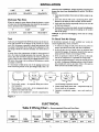
ELECTRICAL
Table II Wiring
Chart
-
Recommended
Wire
and Fuse Sizes
Distance in FeetfromMotorto
Motor
Horsepower
1/2
Volts
115/230
Max. Load
Branch
Fuse*
Amps.
8.8/4.4
Rating Amps
1_15
0'to
100'
101'to
200'
201'to
300'
Meter
301'to
400'
401'to
500'
8/14
8/12
Wire Size
14/14
12/14
10/14
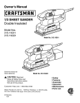
ELECTRICAL
Disconnect
power
before
working
on pump,
Your Motor Terminal
Board (under the motor end cover)
and Pressure Switch look like one of those shown below,
Convert to 115 Volts as shown. Do not change motor wiring
_
switch,
or wiring.
- Motor wires connect here.
Power supply wires connecthere,
230 Volt: Connect 2 hot wires (black and red)
here and cap the white(neutral) wire. It does
not matter whichwire goes to whichscrew.
115 Volt: Connect one hot wire (black or red)
to one of these screws (it doesn'tmatter
which one). Connect the white (neutral)wire
to the other screw. Cap any remaining
black or red wires.
2. Plug in again
Ground
with arrow
.;.'.'.'.'.'.'.'.'._/^
on plug
/'/_'_iI_ crew
pointing to
_._'_'
'115 Volts'.
pressure
if line voltage is 230 Volts or if you have a single voltage
motor: Connect
power
supply as shown for your type of
switch and your supply voltage.
230 Volt to 115 Volt Conversion, Plug-in Type:
1. Pullplug
straight
out from
terminal
board.
motor,
_
Clamp the power cable to prevent strain
on the terminal screws.
green (or bare copper) ground wire
to the green ground screw.
Motor wires connect here,
230 Volt to 115 Volt Conversion, Spade Connector Type:
2. Move white wire
3. Change Complete:
with black tracer
from B to A.
-Power supply wires connecthere.
230 Volt: Connect 2 hot wires (black and red)
here and cap the white (neutral)wire. It does
not matter whichwire goes to whichscrew.
115 Volt: Connect one hot wire (black or red)
to one of these screws (it doesn't matter
which one), Connect the white (neutral)wire
to the other screw. Cap any remaining
black or red wires,
1. Move black wire
from A to L1.
'Gcr
r°eLwnd
2
prevent strain
on the terminal
screws.
green (or bare copper) ground wire
to the green ground screw.
Figure 4: Motor
wiring connections
{_'WARNINGI Hazardous
kill. Connect
ground
supply
wires. Use the
wire) specified
in the
the pnmp to a separate
ances on it.
voltage.
shock,
Pressure Switch. Match motor
born,
Connection
or
wire before
connecting
power
wire size (including
the ground
wiring
chart.
If possible, connect
branch circtdt with no other appll-
[,_WARNING] Explosion
supply
Can
through
hazard.
Do not ground
1.
2.
CONNECTIONS
I_'WARNING ] Fire
hazard.
Incorrect
voltage
can cause
a
Install, ground, wire, and maintain
your pump in compliance with the National
Electrical
Code (NEC) or the
Canadian Electrical Code (CEC), as applicable,
and with all
local codes and ordinances
that apply. Consult your local
building inspector
for code information.
Procedure:
Connect the grotmd wire first as shown in Figure 4. The
ground wire must be a solid copper wire at least as large
as the power supply wires.
There must be a solid metal connection
between
the
3.
Connect thc ground wire to a grounded lead in a service
panel, to a metal underground
water pipe, to a metal
well casing at least ten feet (3M) long, 9,$"to a ground
electrode provided by the power company or the hydro
authority.
4.
Connect the power supply
as shown in Figure 4.
fire or seriously damage the motor and voids the warranty.
The supply voltage must be within _+10% of the motor name*
plate voltage.
- _
;.
NOTICE:
Dual-voltage
motors are factory wired for 230
volts. If necessary,
reconnect
the motor for 115 volts, as
shown. Do not alter the wiring in single voltage motors.
voltage to line voltage.
pressure switch and the motor for motor grounding
protection. If the pressure
switch is not connected
to the
motor, connect the green ground screw in the switch to
the green ground screw under the motor end cover. Use
a solid copper wire at least as large as the power supply
wires.
to a gas
line.
WIRING
31870398
wires to the pressure
switch
OPERATION
Priming
the
will probably
prime the first time after
steps 1 through 4 above.
Pump
NOTICE: To properly
prime the pump, install a pipe tee in
the discharge
piping (see Figure 1, Page 4).
To prevent damage to internal-parts,
pump has been filled with water.
To prime pump:
1. Remove priming
Page 4).
plug
do not start motor
From 10 to 20 foot depths, you might have to shut off
the pump and repeat steps 1, 2 and 3 several times.
until
If, after
pumped,
5.
(Purchase
separately;
2.
Fill pump
3.
Replace priming plug, using Teflon
Stik 2 on plug threads; tighten plug.
4.
Start the pump. Water should be pumped
If not, repeat steps 1, 2 and 3.
Figure
1,
depths
to water
tape or Plasto-Joint
times,
A. Be sure suction
pipe is in the water.
B. Be sure suction
pipe does not leak.
no
water
is
too high
D. As long as foot valve and check valve function correctly and suction pipe does not develop leaks, pump
should not need repriming
in normal service.
in 1-2 minutes.
(10 feet or less), the pump
priming
pump
several
check the following:
C. Be sure that pump is not trying to lift water
(see "Piping in the Well", Page 4).
with water.
On shallow
the following
-"Lake
Chemical
Co., Chicago,
Illinois
MAINTENANCE
Lubrication
C. Remove
It is not necessary
to lubricate
the pump or its motor. The
motor bearings are lubricated
for life. The mechanical
shaft
seal in the pump is water lubricated
and self-adjusting.
Draining
shock.
and relieve
Disconnect
it is disconnected
all pressure
on system
from
Open faucet
proceeding.
3.
Disconnect
pressure
switch tube (Key No. 17, Page 12)
at barbed elbow on pressure
switch (Key No. 28) and
allow tube to drain.
(Key No. 22, Page 12) on pump
to drain.
before
body
5.
Remove priming plug to vent pump; disconnect
(Key No. 6, Page 14) at tank end and drain pressure
and all piping to a point below the frost line.
6.
Be sure to drain any piping that may be cut off from normal system drain due to check valve installation.
hose
tank
Bag Removal
[AWARNING] Risk of electric
shock. Disconnect
before
working
on unit.
1. DISCONNECT
POWER TO PUMP.
power
closest
B. Open
body.
draincock
No.
22, Page
12) on
pump
or fatal
injury,
released
from
be
tank
tank inlet flange (Key
to break seal. Remove
7. Clean and dry inside of tank.
8. Place replacement
bag on a clean
up. Flatten bag and force air out.
9. Tightly
10.
roll bag towards
center
surface
with opening
opening.
Before center opening is covered up, force air out of remaining portion of bag. Finish rolling bag.
11. To make bag easier to insert
of bag with talcum powder.
into tank,
sprinkle
outside
12. Being careful not to break valve, stand tank on end. Push
tightly rolled bag into tank.
14. Clean center
opening
out sidewalls.
You need
not
ring on bag and lip on tank.
15. Pufl ring on bag through tank opening and fit over tank
lip. BE SURE it seats properly in groove on tank lip.
16. Clean sealing
surface
Tighten
A. Hand tighten
of inlet flange and"pla'ce
on studs.
nuts as follows:
all nuts.
one nut snug.
C. Tighten opposite nut snug.
D. Proceed, tightening opposite
to tank.
(Key
serious
6. Wherever convenient,
hold bag with pliers and cut with
single-edge razor blade or sharp knife. Bag will not come
out in one piece. Continue pulling and cutting until bag
is removed.
B. Tighten
as follows:
faucet
by removing
from tank and pump.
5. Remove nuts and washers from
No. 2, Page 14). Tap inlet flange
flange.
17. NOTICE:
A. Open
piping
13. Reach into bag and push
remove all wrinkles.
[,I_WARNING] Be sure ALL air pressure
has been released
from tank before
removing
nuts from flange.
Failure to do this may result in serious
or fatal injury.
Do not attempt
to .open tank unless
all pressure
has
been relieved!
2. Drain system
outside
in system
sure all air pressure
has been
before proceeding
to step 5.
power
2.
Open draincock
and allow pump
ALL air pressure
[&WARNING] To avoid
Pump should be drained whenever
service or is in danger of freezing.
1. DISCONNECT
POWER.
Vinyl
4. Disconnect
for Winter
La' _AMNtr_ta j Risk of electric
before
working
on unit.
4.
hose (Key No. 6, Page 14) from tank flange.
3. Relieve (expel)
valve core.
pairs to a snug fit.
E. Recheck all nuts, using same pattern.
are tight and you have a good seal.
Be sure all nuts
MAINTENANCE
2. Reassembly
NOTICE: DO not overtighten; you may twist studs off of
tank. If you have a torque wrench,
tighten to 85 inchpounds torque.
18. Stand tank on feet and reconnect
19. Recharge
tank to proper
20. Reconnect
hoses
(see Page 6).
switch
1 through
=O" rings with petroleum
jelly, and place in
(see Page 5).
C. Slide pump
tube; prime pump
D. Clean inside of clamp. Place clamp around pump
halves. Alternately tighten clamp screw and tap clamp
around outside with plastic mallet. This will insure
proper seating of "O" ring and clamp.
Air Valve Replacement
1. Follow steps
Page 7.
of pump.
=O" rings and "O" ring grooves.
B. Lubricate
grooves.
piping.
air pressure
and pressure
A. Clean
E. Assemble
base mounting
bolts. Connect
switch tubing and close drain cock.
5 under _Vinyl Bag Removal",
2. Cut valve off as close to tank as possible.
portion back into tank.
3. Tip tank on end and BE SURE all water
bag.
pressure
F. Prime pump and turn on power.
G. Check for leaks.
Push remaining
is drained
halves together.
from
Removing
Motor
for Service
and Replacing Shaft Seal
4. Carefully remove bag ring from lip on tank opening and
push bag ring back into tank; reach in around it and remove cut off portion of valve from tank.
valve
If it is he4:_essary to separate motor and seal plate, always replace the shaft seal. We suggest you purchase
this item,
UlO94SA, and have it on hand for future use.
6. Pull valve through hole with pliers or a valve tool (available at your local filling station or Automotive
Center).
NOTICE: The seal consists of two parts, a rotating member
and a ceramic seat. The surfaces of the seal are easily damaged. Read instructions
carefully.
5. Wipe a thin film of soapy solution on replacement
and from inside tank insert in hole in top of tank.
7. Follow steps 14 through 20 under
Page 7, to reinstall bag in tank.
Testing
"Vinyl Bag Removal",
1. Disassemble
for Bag Leakage
1. Follow steps
Page 7.
2. Tip tank
valve!
1 through
on end,
vane
A. Remove
4 under
down.
"Vinyl Bag Removal",
Be careful
shock.
Ground
unit
holding
screws
C. Place 7/16" open
D. Turn impeller
bag
above.
as follows
(Key Nos. 8 and
diffuser.
and remove
end wrench
counterclockwise
motor
canopy
on motor shaft flat.
when
facing it.
and
disconnect
power
before
attempting
any work
on
pomp
or motor.
Your Sears pump is designed
for ease in servicing. Should
repair or replacement
of the motor or seal be needed, the
pump and piping do not need to be disconnected
or distuthed.
1. Disassemble
pump
A. Disconnect
as follows:
power.
B. Drain pump by opening drain cock. Remove
switch tubing from fitting on top of pump.
_WARNING]To
avoid
pressure
fi'om system
clamp from pump.
C. Remove
clamp,
serious
before
injory,release
attempting
pressure
all
to remove
4750194
Key No. 10, Page 12.
Figure 5
D. Remove pump base motmting bolts. Motor assembly
and back half assembly of pump can he pulled away
from front half.
E. Remove
from
3. Remove pump back half from motor by unscrewing
four
(4) nuts. Pry back half off motor by inserting
two (2)
screwdrivers
between the back pump half and the motor
flange. This will force rotating portion of seal off shaft.
See Figure 5.
DISASSEMBLY
AND
ASSEMBLY
OF PUMP
of electric
per instructions
screws
B. Loosen two
motor.
not to break
3. If bag leaks, water will run out of valve. If so, replace
as instructed
above.
I
I_.WARNING JRtsk
pump
2. Remove diffuser and impeller
9, Page 12).
"O" rings.
8
MAINTENANCE
4. Place back half of pump on flat surface
ramic seat. See Figure 6.
and tap out ce-
I. Screw impeller on shaft (clockwise)
while holding
shaft with 7/16" open end wrench on shaft flats. This
will automatically
locate seal in place. See Figure 8.
478 0194
4790t94
Figure 6
Figure 8
5. Clean seal cavity.
6. Install new seal.
A. Clean
cloth.
polished
surface
of ceramic
seat with
B. Wet outer edge of "O" Ring with detergent
J. Remount
clean
Cleaning
solution.
E. Clean motor
F. Reassemble
washer
G. Apply detergent
ing seal member.
solution
Cleaning
Shallow
To remove
lows:
debris
from
Well
per
and
Jet
venturi
or nozzle,
proceed
as fol-
socket wrench is not available, insert an ice pick or similar pointed tool carefully into the nozzle. This will dislodge debris.
and clean
surface
3. Flush out the debris by running water through the nozzle in the same direction
as the dislodging tool was inserted.
of
4. Reinstall nozzle
to motor.
to inside
and
1. Disassemble
pump per instructions
on Page 8.
2. Turn venturi counterclockwise
and remove it. The nozzle is now exposed. Remove it using a 5/8" hex socket
wrench
with extension.
Turn counterclockwise.
If
shaft.
back half of pump
"Disassembly
3. Clean impeller and reassemble
impeller and diffuser
instructions
under "Removing
Motor for Service
Replacing Shaft Seal" on Pages 8 and 9.
Figure 7B
of cardboard
Impeller
2. Remove diffuser and impeller from pump per instructions under "Removing Motor for Service and Replacing
Shaft Seal" on Page 8.
483 0194
D. Dispose
seat.
on seal plate.
1. Follow steps 1A through
1E under
Assembly of Pump _ on Page 8.
C. With finger pressure
press seat firmly and squarely
into cavity. See Figure 7A. Polished face of seat faces
inside of pump. If seat will not locate properly, place
cardboard
washer over polished face and use piece of
3/4" standard pipe for pressing purposes.
See Figure
7B.
Figure 7A
diffuser
diameter
5. Reassemble
of rotat-
H. Slide rotating member on shaft tmtil rubber drive ring
hits shaft shoulder. NOTICE: BE SURE you do not chip
or scratch seal face on shaft shoulder or seal will leak!
9
and venturi.
pump
Do not ove.rtighten_
per instructions
on Pages 8 and 9.
HELPFUL
How
to Handle
a Gaseous
HINTS
Well
In some areas well water contains gases which must be allowed to escape before the water is used. This can be done
as shown in Figure 9.
Gases
rise to
suflace
A good way of delivering gas-free water is to suspend a pipe,
closed at the bottom and open at the top, surrounding
the
suction pipe. Since the gases rise in the well casing, the
water sucked down through
the pipe and into the suction
pipe is free of gas, This type of wen must be vented to the
outside of any enclosure.
pipes_eeve
Not
to
pipe
valve
Scale
2_03_
sleeve
cap
Figure 9
lO
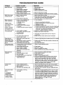
TROUBLESHOOTING
TROUBLE
POSSIBLE
Motor will not run
1.
2.
3.
4,
CAUSES
GUIDE
REMEDIES
Disconnect switch is off
Fuse is blown
Starting switch is defective
Wires at motor are loose,
disconnected, or wired incorrectly
*5. Motor is wired incorrectly
6. Pressure switch contacts are dirty
1.
2.
3.
4.
Motor runs hot and
overload kicks off
"1. Motor is wired incorrectly
2. Voltage is too low
Motor runs but no
water is delivered
"1. Pump in a new installation did
not pick up prime through:
a. Improper priming
b. Air leaks
c. Leaking foot valve
*2. Pump has lost its prime through:
a. Air leaks
b. Water level below suction of pump
1, Refer to instructions on wiring
2. Check with power company. Install heavier wiring
if wire size is too small. See wiring instructions
3. See section below on too frequent cycling
1. In new installation:
5. Refer to instructions on wiring
6. Clean by sliding piece of plain paper between contacts
3. Pump cycles too frequently
(*Note: Check
prime before looking for other
z:auses. Unscrew
priming plug and
see if there is water
in priming hole)
3. Jet or impeller is plugged
4. Check valve or foot valve is stuck
in closed position
5. Pipes are frozen
1. Water level in well is lower than
estimated
2. Steel piping (if used) is corroded or
limed, causing excess friction
3, Offset piping is too small in size
Pump pumps water
but does not shut off
1. Pressure switch is out of adjustment
or contacts are "frozen"
2. Faucets have been left open
3. Jet or impeller is clogged
4. Motor is wired incorrectly
5. Water level in well is lower than
estimated
a.
b.
c.
2. In
a.
b.
Re-prime according to instructions
Check all connections on suction line and jet
Replace foot valve
installation already in use:
Check all connections on suction line, jet and shaft seal
Lower suction line into water and re-prime. If receding
water level in a shallow well operation exceeds
suction lift, a deep well pump is needed
3. Clean jet or impeller according to instructions
4. Replace check valve or foot valve
5. Thaw pipes. Bury pipes below frost line. Heat pit or
pump house
6. Raise foot valve and/or strainer above well bottom
6. Foot valve and/or strainer are
buried in sand or mud
Pump does not
deliver water to full
capacity (also check
point 3 immediately
above)
Be sure switch is on
Replace fuse
Replace starting switch
Refer to instructions on wiring
1. A deep well jet pump may be needed (over 20 ft. to water
2. Replace with Plastic Pipe where possible, otherwise with
new steel pipe
3. Use larger offset piping
1. Adjust or replace pressure switch
2.
3.
4.
5.
Close faucets
Clean jet or impeller
Refer to instructions on wiring
Check possibility of using a deep well jet pump
Pump cycles too
frequently
1. Pipes leak
2. Faucets or valves are open
3. Foot valve leaks
4. Pressure switch is out of adjustment
5. Air charge too low in
Captive Air_ Tank
1. Check connections, replace pipe fittings
2. Close faucets or valves
3. Replace foot valve
4. Adjust or replace pressure switch
5. Disconnect electrical power and open faucets until all
pressure is relieved. Using automobile tire pressure
gauge, check air pressure in tank at the valve stem
located at top of tank. If less than 40 pounds, pump air
into tank from outside source, until 40 pounds pressure
is reached. Check air valve for leaks, using soapy
solution, and replace core if necessary
Air spurts from
faucets
1. Pump is picking up prime
2. Leak in suction side of pump
3. Well is gaseous
4. Intermittent over-pumping of well
1.
2.
3.
4.
Leaks at the metal
clamp
1. Loose clamps or "O" ring
not sealed
1. First check the clamp tightening screw to see if it is tight.
If it is tight and slight leakage still occurs, place a piece
of wood on the periphery of the clamp and firmly tap the
wood with a hammer. Repeat this operation.around the
edge of the clamp and retighten the clamp screw. If leak
continues, disassemble clamp and pump halves and
check to see that "O" ring is propedy seated and no
foreign material is on "O" ring or "O" seat.
Reassemble pump.
[J_WARNING]
Release all pressure
in system before
working on clamp!
]]
As soon as pump picks up prime, all air will be ejected
Check suction piping, make sure joints are not sucking air
Change installation as described in manual
Lower foot valve if possible, otherwise res_ct..discharge
side of pump
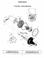
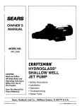
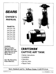
REPAIR PARTS
Pump Only - Model 390.252158
1c
2
29
28
30
3
4
8
I
9
lO
24
11
16 17
\
23
19
2O
22
To Order Parts in the U.S.A., Call
Sears Product Service, 1-800-366-7278
.
21
TO Order Parts outside the U.S.A., Call
Your local Sears Service Center or Store
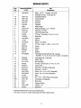
REPAIR PARTS
Key
No.
Model 390.252158
1/2 HP
Part
Description
1"*
J218-953C
Motor- 1/2 HP - 115/230V - 60 Cycle
1A
U18-1103
1B
U18-1180
(Includes Key Nos. 1A through 1E)
Overload Protector
Terminal Board
1C
U18-1098
Contactor
1D
U18-128
Governor
1E
U18-526
Capacitor
2
C69-2
Water Slinger
3*
U78-107PT
4
WC78-41T
Reducer Bushing -_1/2" x 1/8" NPT
Pipe Plug - 1/8" NPT
5
L176-47P
Tank Body (Back Half)
6
U9-399
7
U109-6A
"O" Ring - Tank Body - 9-1/2" x 9" x 1/4"
Shaft Seal
8
J105-40PE
9
J1-39P
Impeller
Diffuser
10
C19-54SS
Clamp - Tank Body
11
U9-201
12
N32P-66
"O" Ring - Venturi - 1-3/8" x 1-1/8" x 1/8"
Venturi
13
N34P-19
Nozzle
14
N76-29P
Insert
15
J20-18
Gasket
16
N176-28PB
Tank Body Assembly (Front Half - Includes
Key No's. 11, 12, 13, 14, 15, 16, 19, 20, 21,23 and 24)
16
N76-28P
17
U37-673P
Tank Body Only - Front Half
Switch Tube
18
U111-212T
90 ° Hose Barb
19
U9-226
20
N166-5P
"O" Ring - Check Valve - 2-1/4" x 2" x 1/8"
Check Valve
2:1"
WC78-41T
22
U212-68T
Pipe Plug - 1/8" NPT (2 Required)
Draincock - 1/4" NPT
23
U30-742SS
Screw - #10 - 16 x 1-1/8 ° (4 Required)
24
U30-542SS
25
C4-42P
Screw - #8 - 32 x 7/8" (5 Required)
Base
26*
U36-37ZP
Nut - 5/16" - 18 Hex Head (4 Required)
26A
U43-11ZP
27
C35-11
Lockwasher (4 Required)
Motor Pad
28
2782
Pressure Switch
29
U36-112ZP
3O
L43-5C
Locknut - 1/2"
"Connector
* Standard hardware item, may be purchased locally.
** For repair or service to motors, always give the motor model number.
13
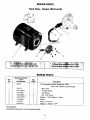
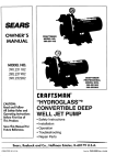
REPAIR PARTS
Tank Only - Model 390.252158
7
REPAIR PARTS
Key
No.
Model 390.252158
1/2 HP
Part Number
1
Qty.
Used
Description
29135
1
U20-13
1
Bag - Vinyl
U212-160 t
U31-446P
1
Air Valve w/Cap
1
6
Inlet Flange
N_ - 5/16-18 Hex
5
U36-2.02BT 1
U78-777PA 1"
U19-55SS
6
U74-37H
7
U78-777P
Tank Assembly (Includes Diaphragm, Elbow,
Valve, Nuts, Washers, & Inlet Flange)
2
3
4
1
Adapter - 1" NPT (Male) x 1° Insert
2
1
Clamp
Hose - 1" x 24-1/2"
1
Adapter - 1" Pipe to 1" NPT
• Not illustrated.
t Standard hardware item, may be purchased locally.
14
15
SEARS
OWNER'S
MANUAL
Model No.
390.252158
CRRFTJ;MRN°
PROFESSIONAL
1/2 HP SHALLOW WELL
WATER SYSTEM
Forthe repair or replacementpartsyouneed
Call7 am - 7 pro, 7 daysa week
1-800-366-PART
(1-800-366-7278)
Forin-homemajorbrandrepair service
Call24 hoursa day, 7 days a week
1-800-4-REPAIR
(1-800-473-7247)
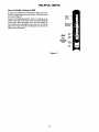
The model number of
your Shallow Well Water
Systemwill be found on
the pump body.
When requesting service
or ordering parts, always
give the following
information:
• Product Type
• Model Number
• Part Number
Forthe locationof a
SearsRepairServiceCenterin yourarea
Call24 hours a day,7 daysa week
1-800-488-1222
Forinformationon purchasinga Sears
MaintenanceAgreementor to inquire
aboutan existingAgreement
call g am - 5 pro,Monday-Saturday
1-800-827-6655
-
SEARS
• Part Description
Amenca_
Repair SpecialisLs
Sears, Roebuck and Co., Hoffman Estates, IL 60179
U.S.A.