1
6.1 Channel
Home Theatre Receiver
OWNER S MANUAL
CAUTION
RI SK OF ELECTRI C SHOCK
DO NOT OPEN
CAUTION: TO REDUCE THE RISK OF ELECTRICAL SHOCK, DO NOT
REMOVE COVER (OR BACK). NO USER-SERVICEABLE PARTS
INSIDE. REFER SERVICING TO QUALIFIED SERVICE
The lightning flash with arrowhead symbol, within an equilateral triangle, is intended to alert the user to the
presence of uninsulated dangerous voltage within the product s enclosure that may be of sufficient
magnitude to constitute a risk of electric shock to persons.
The exclamation point within an equilateral triangle is intended to alert the user to the presence of
important operating and maintenance (servicing) instructions in the literature accompanying the
appliance.
WARNING: TO PREVENT FIRE OR SHOCK HAZARD, DO NOT EXPOSE
THIS APPLIANCE TO RAIN OR MOISTURE.
01
IMPORTANT SAFETY INSTRUCTIONS
FOREWORD
This section must be read before any connection is
made to the mains supply.
WARNINGS
Do not expose the equipment to rain or moisture.
Do not remove the cover from the equipment.
Do not push anything inside the equipment through
the ventilation holes.
Do not handle the mains lead with wet hands.
EQUI PMENT MAI NS WORKI NG SETTI NG
Your ELTAX product has been prepared to
comply w it h t he household pow er and saf et y
requirements that exist in your area.
AVR-800 can be powered by 230 V AC only.
I MPORTANT:( FOR UK VERSI ON)
This apparatus is fitted with an approved moulded
13 Amp plug.
To change a fuse in this type of plug proceed as
follows:
1. Remove fuse cover and fuse.
2. Fix new f use w hich should be a BS1362
13A,A.S.T.A or BSI approved type.
3. Refit the fuse cover.
I f the fitt ed plug is not suit able for your socket
outlets, it should be cut off and an appropriate plug
fitted in its place.
If the mains plug contains a fuse. this should have a
value of 13A.
I f a plug without a fuse is used. the fuse at the
distribution board should not be greater than 5A.
ABOUT THI S USER GUI DE
Refer to the figures on page 2 of this user guide. All
references to the controls that are printed in BOLD
type are as they appear on the unit.
PRECAUTIONS
The following precaut ions should be t aken when
operating the equipment.
GENERAL PRECAUTI ONS
When siting the equipment ensure that:
-The ventilation holes are not covered;
-Air is allowed to circulate freely around the euipment
-It is on a vibration free-surface;
-It will not be exposed to interference from an external
source;
-I t will not be exposed t o excessive heat , cold,
moisture or dust;
-It will not be exposed to direct sunlight;
-It will not be exposed to electrostatic discharges
Never place heavy objects on the equipment.
If a foreign body or water does enter the equipment,
contact your nearest dealer or service centre.
Do not pull out the plug by pulling on the mains lead,
hold the plug.
I t is advisable when leaving the house, or during a
thunderstorm. to disconnect the equipment from the
mains supply.
The equipment draws nominal
nonoperating power from the AC outlet
with its POWER switch in the STANDBY
position.
Note:
The severed plug must be destroyed to avoid a
possible shock hazard should it be inserted into a
13A socket elsewhere.
HOW TO CONNECT A PLUG
The w ir es in t he mains lead ar e colour ed in
accordance with the following code.
BLUE-"NEUTRAL"("N")
BROWN-"LIVE"("L")
1. The BLUE wire must be connected to the terminal
which is marked with the letter "N" or coloured
BLACK.
2. The BROWN wire must be connect ed t o t he
t erminal which is marked wit h t he let t er "L" or
colourde, RED.
3. Do not connect either wires to the earth terminal in
the plug which is marked by the letter "E" or by the
safety earth symbol or coloured green-and-yellow.
Before replacing the plug cover. make certain that
the cord grip is clamped over the sheath of the
lead-not simply over the two wires.
COPYRIGHT
Recording and playback of any material may require
consent. For further information refer to the following:
-Copyright Act 1956
-Dramatic and Musical Performers Act 1958
-Performers Protection Acts 1963 and 1972
-any subsequent statutory enactments and orders.
02
Contents
WARNING:
TO PREVENT FI RE OR SHOCK
HAZARD, DO NOT EXPOSE THI S
APPLIANCE TO RAIN OR MOISTURE.
This symbol means that the
product is double insulat ed
and you do not need an earth
connection
Before Use..................................................................................4
Description .................................................................................5
Connection .................................................................................6
Remote Control Unit ....................................................................12
Basic Operations.........................................................................13
Radio Reception .........................................................................15
RDS Operations ..........................................................................17
Video Operations........................................................................18
This symbol means that this
product keeps to the European
saf et y
and
elect rical
interference directives
Playing Video Sources............................................................18
Tape Dubbing........................................................................18
S.A.V.E System Function.........................................................18
Available Surround Modes...........................................................19
CAUTION Regarding
Speaker Configuration.................................................................22
Placement
Delay Time.................................................................................23
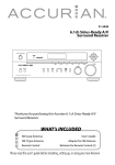
To maintain proper ventilation, be
sure t o leave a space around t he
unit (from the largest outer
dimensions including projections)
equal t o, or great ed t han, shown
below :
Test Tone ...................................................................................24
Troubleshooting...........................................................................25
Specifications ..............................................................................26
Left and right Panels : 10cm
Rear Panel
: 10cm
Top Panel
: 50cm
INTRODUCTION
This instruction manual is important to you. Please read it. In a short time it shows exactly how to connect, operate and adjust
this unit for best performance.
It can save you money. It shows simple things to do and check before you call for help and can save the cost of unnecessary
service or call out charge.
WARNING: TO REDUCE THE RISK OF FIRE OR ELECTRIC SHOCK, DO NOT EXPOSE THIS APPLINACE TO RAIN OR MOISTURE.
DANGEROUS HIGH VOLTAGES ARE PRESENT INSIDE THE ENCLOSURE. DO NOT OPEN THE CABINET. REFER
SERVICING TO QUALIFIED PERSONNEL ONLY.
03
Before Use
Read this before operation
Before Connection
Read this before operation
CAUTION
< Choose the installation location of your unit carefully.
Avoid placing it in direct sunlight or close to a source of
heat. Also avoid locations subj ect to vibrations and
excessive dust, heat, cold or moisture.
< The ventilation holes should not be covered. Make sure
t here is enough space above and beside t he
amplifier/ receiver (about 4 inches). Do not place a CD
player or other equipment on top of the amplifier/ receiver.
< Do not open the cabinet as this might result in damage to
the circuitry or electrical shock. If a foreign object should
get into the set, contact your dealer.
< When removing the power plug from the wall outlet,
always pull directly on the plug, never yank the cord.
< Do not attempt to clean the unit with chemical solvents
as this might damage the finish. Use a clean, dry cloth.
< Keep this manual in a safe place for future reference.
Turn off the power of all the equipment before making
connections.
Read instructions of each component you intend to use
with this unit.
< Be sure to insert each plug securely. To prevent hum
and noise, do not bundle the connection cords with the
power cord or speaker cord.
Speaker Connections
Caution:
To avoid damaging the speakers with a sudden high-level
signal, be sure to switch the power off before connecting
the speakers.
Back-up Memory Function
< Check the impedance of your speakers.
Connect speaker with an impedance of 8 ohms or more.
The amplif ier's red speaker t erminals are t he +
(positive) terminals and the black terminals are the _
(negative) terminals.
< The + side of the speaker cable is marked to make it
distinguishable from the _ side of the cable. Connect
this marked side to the red + terminal and the unmarked
side to the black terminal.
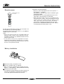
< Prepare the speaker cords for connection by stripping
off approximately 10 mm or less (no more as this could
cause a short-circuit) of the outer insulation.
Twist the wires tightly together so that they are not
straggly :
This is the function which preserves the preset memory and
most-recent memory functions. I n the event of a power
failure, or if the power cord of this unit is disconnected from
the electric outlet, the back-up memory will preserve the
preset memory and most-recent memory functions for as
long as approximately 3 days.
If the power supply is interrupted for 3 days or longer, the
memory settings will be erased.
When to Use RESET Switch
< When this system is subjected to an electrical shock.
< When the power is irregular.
In these cases, try the following
Press the TUNING MODE button for more than 5 seconds.
Note:
If the TUNING MODE button is pressed for more than 5
seconds Standby mode, all the memory will be erased.
How to connect
Press the lever, insert the stripped and twisted end
(approx. 3/ 8") of the cord, then release the lever :
Make sure it is fastened securely by pulling the cord
lightly.
04
DESCRIPTION
DTS was introduced in 1994 to provide 5.1 channels of
discrete digital audio into home theater systems.
DTS brings you premium quality discrete multi-channel
digital sound to both movies and music.
DTS is a multi-channel sound system designed to create full
range digital sound reproduction.
The no compromise DTS digital process sets the standard
of quality for cinema sound by delivering an exact copy
of the studio master recordings to neighborhood and home
theaters.
Now,every moviegoer can hear the sound exactly as the
moviemaker intended.
DTS can be enjoyed in the home for either movies or music
on of DVD's, LD's, and CD's.
DTS-ES Extended Surround is a new multi-channel digital
signal format developed by Digital Theater Systems I nc.
While offering high compatibility with the conventional
DTS Digital Surroud format, DTS-ES Extended Surround
greatly improves the 360-degree surround impression and
space expression thanks to further expanded surround
signals. This format has been used professionally in movie
theaters since 1999.
In addition to the 5.1surround channels (FL, FR, C, SL, SR
and LFE), DTS-ES Extended Surround also offers the SB
(Surround Back) channel for surround playback with a total
of 6.1 channels. DTS-ES Extended Surround includes two
signal format s with different surround signal recording
methods, as DTS-ES Discrete 6.1 and DTS-ES Matrix 6.1.
"DTS"and "DTS Digital Surround" are registered trademarks
of Digital Theater Systems, Inc.
" DTS" , " DTS-ES Ext ended Sur round" and " Neo: 6" are
trademarks of Digital Theater Systems, Inc.
The advantages of discrete multichannel systems over
matrix are well known.
But even in homes equipped for discrete multichannel,
there remains a need for high-quality matrix decoding. This
is because of the large library of matrix surround motion
pictures available on disc and on VHS tape; and analog
television broadcasts.
The t ypical mat rix decoder of t oday derives a cent er
channel and a mono surround channel from two-channel
matrix stereo material. I t is better than a simple matrix in
that it includes steering logic to improve separation, but
because of it s mono, band-limit ed surround it can be
disappoint ing t o user s accust omed t o discret e
multichannel.
Dolby Digital identifies the use of Dolby Digital (AC-3) audio
coding for such consumer formats as DVD and DTV. As with
film sound, Dolby Digital can provide up to five full-range
channels for lef t , cent er, and right screen channels,
independent left and right surround channels, and a sixth (
".1") channel for low-frequency effects.
Dolby Surround Pro Logic I I is an improved matrix decoding
technology that provides better spatiality and directionality
on Dolby Surround program material; provides a convincing
three-dimensional soundfield on conventional stereo music
recordings; and is ideally suit ed t o bring t he surround
experience t o aut omot ive sound. While convent ional
surround programming is fully compat ible wit h Dolby
Surround Pro Logic II decoders, soundtracks will be able to
be encoded specifically to take full advantage of Pro-Logic
I I playback, including separat e left and right surround
channels. ( Such mat erial is also compat ible wit h
conventional Pro Logic decoders. )
Neo6 offers several important improvements as follow.
< Neo 6 provides up to six full-band channels of matrix
decoding from stereo matrix material. Users with 6.1 and
5.1 systems will derive six and five separate channels,
respect ively. corresponding t o t he st andard hometheater speaker layouts.
Dolby Digital EX creates six full-bandwidth output channels
from 5.1-channel sources. This is done using a mat rix
decoder that derives three surround channels from the two
in the original recording. For best results, Dolby Digital EX
should be used with movies soundtracks recorded with
Dolby Digital Surround EX.
< Neo 6 technology allows various sound elements within
a channel or channels to be steered separately, and in a
way which follows nat urally f rom t he or iginal
presentation.
< Neo 6 offers a music mode to expand stereo nonmatrix
recordings into the five-or six-chnnel layout, in a way
which does not diminish the subtlety and integrity of the
original stereo recording.
Manufact ured under license from Dolby Laborat ories.
"Dolby", "ProLogic", and the double-D symbol are trademarks
of Dolby Laboratories.
05
Connection
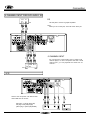
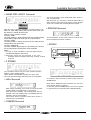
SPEAKERS, PRE OUT, AC OUTLETS
(OPTIONAL)
POWERED
SUBWOOFER
SURROUND
BACK
SURROUND
SURROUND
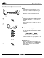
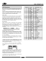
Power cord (AC)
AC OUTLETS (SWITCHED)
Be sure to connect the power cord to an AC outlet
which supplies the correct voltage.
Hold the power plug when plugging or unplugging the
power cord.
These out let s are only act ive when t he receiver is
turned on.
Caution:
Make sure t hat t he t ot al power consumpt ion of all
equipment connected to the outlets on the receiver does
not exceed 100 watts.
PRE OUT ( SUB WOOFER ) jack
Use t his j ack t o connect a powered sub-woofer or
passive sub-woofer with a power amplifier (OPTIONAL) .
06
Connection
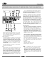
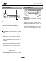
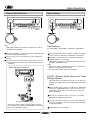
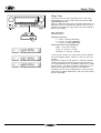
6 CHANNEL INPUT FOR DVD AUDIO, EQ
OUT
EQ
IN
Use this jack to connect a graphic equalizer.
EQ
Note:
When you do not the jack, You must insert "short pin".
6 CHANNEL INPUT
SR SL
DVD
By connect iong a DVD Audio player, SACD mult i
channel player, or other component that has a multi
channel port , you can playback t he audio wit h 5.1
channel.
SW C
6CH OUT
VCR
Connect the component with RCA to RCA
cords. Make sure to connect :
white plug to white jack(L:left)
red plug to red jack(R:right)
yellow plug to yellow jack(VIDEO)
07
Connection
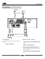
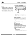
DVD PLAYER, CABLE BOX, SATELLITE RECEIVER (DSS), TELEVISION (MONITOR)
S-VIDEO
IN
VIDEO
IN
I f you use both S-Video and RCA composite cables to
connect different video components to the AVR-800, you
must also use both S-Video and RCA composite cables to
connect the TV monitor to the AVR-800.
For example, if you connect a DVD player to the AVR-800
using S-Video cable and a VCR using an RCA t o RCA
composite cable, you must also connect the TV to t he
AVR-800 using both types of cables. This requires an SVideo cable from the S-Video monitor out jack on the AVR800 to an S-Video input on the TV (ie. Video 1). In addition,
you must use an RCA composite cable from the composite
video monit or out j ack on t he AVR- 800 t o an RCA
composite video input on the TV but not the same input used
for the S-Video cable(ie: Video 2). Using this type of dual
cable video connection. you will need to switch the TV
video input source from TV to Video 1 to Video 2 depending
on the video source being played-TV, DVD or VCR.
Audio connections:
Some video component s are equipped wit h special
digital audio outputs (ie: DVD players). I f your video
component is equipped with a digital audio output, it is
recommended that you connect to the AVR-800 using a
digital cable. Digital audio cables are required to use the
DTS and Dolby Digital surround sound modes. If you do
not use digital connections, the AVR-800 will only
operate in Dolby Pro LogicII, Dolby 3 Stereo, Hall, Theater
and Stadium surround modes.
When connect ing video component s such as DVD
players, cable boxes, satellite receivers and televisions,
you can use different types of cables depending on how
the video component is equipped.
There are two types of digital cables - coaxial (75 ohm) and
optical. The AVR-800 i s equipped with both types of digital
inputs. These inputs are labeled DIGITAL/DTS/PCM on the
rear of the unit. Connect the video component outputs to any
one of the three digital inputs on theAVR-800.
Video connections:
If the video component is equipped with S-VIDEO jacks,
it is recommended that it be connected to the AVR-800
or directly to the television monitor using an S-VI DEO
cable. S-Video cables provide better picture clarity and
resolution. If the video component is not equipped with
an S-VI DEO j ack, use a convent ional RCA t o RCA
composite cable to connect to the AVR-800 or directly
to the television.
If the video component is not equipped with a digital output,
use a dual RCA to RCA composite audio cable to connect to
the AVR-800.
Make sure to connect:
White plug to white jack ( L : left )
Red plug to red jack ( R : right )
The above illust rat ion shows how to connect video
components to the AVR-800.
Note:
When an optical cable is used, remove the protection
caps f rom t he component and AVR- 800 before
attempting to insert the optical cable. I f not using an
optical cable or if the cable is removed, always re-install
t he prot ect ion caps t o prevent dirt and dust f rom
entering the inputs. If using a coaxial digital cable, leave
the protection caps in both the video component and
AVR-800.
Note:
When connection more than one video component to the
AVR-800 (ie: VCR and DVD player) it is easier to use
either all S-Video cables or all RCA to RCA composite
cables. This allows both video signals (DVD and VCR) to
be sent through the AVR-800 to the TV monitor using
j ust one video input on t he TV ( S-Video or RCA) .
Regardless of the video component being played DVD or
VCR, the picture will always appear on the same video
input of the monitor.
08
Connection
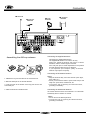
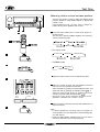
CD, TAPE Jacks
CD, TAPE jacks
DIGITAL IN/ OUT terminals
Connect the component with RCA to RCA cords. Make sure
to connect :
I f t he CD player or t ape player has digit al out put s,
connect the component with coaxial cables or optical
cables.
white plug to white jack(L:left)
red plug to red jack(R:right)
DIGITAL IN to DIGITAL OUT(CD, etc.)
DIGITAL OUT to DIGITAL IN( MD, etc.)
< Connect to any one of the DIGITAL IN terminals.
< When using DIGITAL OPTICAL IN terminals, remove the
caps from the terminals. When you do not use them,
leave the caps in place.
< To record digitally, connect the source(CD player, etc.)
to DI GI TAL I N and the recorder(MD, etc.) to DI GI TAL
OUT.
09
Connection
FM antenna
FM external
antenna
AM loop
antenna
AM external
antenna
Connecting the supplied antennas
Assembling the AM loop antenna
Connecting the supplied FM antenna
The supplied FM antenna is for indoor use only.
During use, extend the antenna and move it in various
directions until the clearest signal is received.
Fix it with push pins or similar implements in the position
that will cause the least amount of distortion.
I f you experience poor reception quality, an external
antenna may improve the quality.
Connecting an FM external antenna
Notes:
< Keep the antenna away from noise sources (neon signs,
busy roads, etc.)
< Do not put the antenna close to power lines. keep it well
away from power lines, transformers, etc.
< To avoid t he risk of light ning and elect rical shock,
grounding is necessary.
1. Release the vinyl tie and take out the connection line.
2. Bend the base part in the reverse direction.
3. Insert the hook at the bottom of the loop part into the slot
at the base par.
Connecting an AM external antenna
4. Place the antenna on stable surface.
An external antenna will be more effective if it is stretched
horizontally above a window or outside.
Notes:
< Do not remove the AM loop antenna.
< To avoid t he risk of lightning and electrical shock,
grounding is necessary.
10
Connection
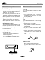
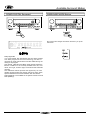
Speaker layout example when using SURROUND MODE or 3 STEREO
SURROUND
3 STEREO
B
A
A
C
B
E (OPTIONAL)
A
A
E (OPTIONAL)
C
D
Positioning of the Speakers
C Surround speakers
The positioning of speakers differs according to the size
and acoustics of the listening room. While actually
list ening t o a program source, t ry various speaker
positions to determine which layout provides the best
surround effect.
I nstall these speakers above the level of the listener's
ears, to the left and right.
Do not install the Surround speakers too far behind the
listening position. I t might be effective to direct the
Surround speakers towards a wall or ceiling to further
disperse the sound.
Place the speakers connected to "L" to your left, and "R"
to your right.
D SURR. BACK SPEAKER
A Front speakers
Use magnetic shielded speakers, if you are using it near
your TV.
Place the front speakers in front of the listening position,
to the left and right of a TV.
Front speakers are required for all surround modes.
Set the distance from a surround back speaker to your
normal listening position between 1 and 30 feet in 1.0foot Intervals (0.3 to 9 meters In 0.3-meter Intervals).
Placce the speaker behind of the listening position.
E Subwoofer (Optional)
Reproduces powerful and deep bass sounds.
Use a subwoofer with built-in amplifier.
A Subwoofer is not required but may be added as an
option.
B Center speaker
Use magnetic shielded speaker, if you are using it near
your TV.
Place a center speaker between the front speakers, on
or below the TV.
This speaker improves sonic imaging and depth of field.
Be sure to connect a center speaker when using the 3
STEREO mode.
11
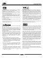
Remote Control Unit
Precautions concerning batteries
Remote sensor
REMOTE
SENSOR
< Be sure to insert the batteries with correct positive " + "
and negative " _ " polarities.
< Use batteries of the same type. Never use different types
of batteries together.
< Rechargeable and non-rechargeable batteries can be
used. Refer to the precautions on their labels.
< When the remote control unit is not to be used for a long
time (more than a month), remove the batteries from the
remote control unit to prevent them from leaking. If they
leak, wipe away t he liquid inside t he bat t ery
compartment and replace the batteries with new ones.
< Do not heat or disassemble batteries and never dispose
of old batteries by throwing them in a fire.
REMOTE SENSOR window
of the receiver
By using the provided remote control unit, the receiver can
be controlled from your listening position.
To use the remote control unit, point it at the REMOTE
SENSOR window of the receiver.
Notes:
< Even if the remote control unit is operated within the
ef fect ive range, remot e cont rol operat ion may be
impossible if there are any obstacles between the unit
and the remote control.
< I f t he remot e cont rol unit is operat ed near ot her
appliances which generate infrared rays, or if other
remote control devices using infrared rays are used near
the unit, it may operate incorrectly.
Battery lnstallation
1 Remove the battery compartment cover.
2 Insert two "AA(UM-3, R6)" dry batteries.
Make sure t hat t he batt eries are insert ed wit h t heir
positive "+ " and negative_" " poles positioned correctly.
3 Close the cover until it clicks.
< If the distance required between the remote control unit
and main unit decreases, the batteries are exhausted.
In this case replace the batteries with new ones.
12
Basic Operations
Basic Operations (1)
3
Basic Operations (2)
4
5
A
2 1
STANDBY/ON Button
When the POWER button is "ON", Press this button to
turn the power on.
Press it again to turn the system off (power standby
mode).
The STANDBY indicator lights up in power standby mode
and goes out when this unit is turned on.
1 Press the POWER button to ON.
2 Press the STANDBY/ ON button to ON.
3 Select the desired source with the FUNCTION (source)
selector.
B
VCR/ VID 1
TV/ VID 2 (OPT 1, OPT 2, COAX)
AUX/ VID 3 (OPT 1, OPT 2, COAX)
DVD/ CD (OPT 1, OPT 2, COAX)
TAPE
CD/ (OPT 1, OPT 2, COAX)
TUNER (frequency)
6CH IN
SPEAKER Select Button
With the unit in the STEREO mode or the SURROUND
MODEs (DTS, DOLBY DI GI TAL, DOLBY PRO LOGI CI I , 3
STEREO, other SURROUND MODES) SPEAKERS A and B
can be selected simultaneously.
Notes:
When the speaker A and B is selected simultaneously,
You must connect certainly speaker both A and B.
4 When TV, DVD, AUX or CD is select ed, press t he
Otherwise speaker is not operate.
DI GI TAL I NPUT but t on and select " OPTI CAL- 1" ,
"OPTI CAL-2", "COAXI AL" or "ANALOG" in accordance
with your connection.
C
If "DIGITAL" blinks on the display:
A digital input souce(OPT 1, 2, COAX) has been selected,
but the source isn't connected or is not switched on.
In that case, connect and switch the source on, or select
ANALOG by pressing the DIGITAL INPUT button.
Bass Control
This control is used for adjusting the level of the low
frequency sound range.
D
Treble Control
This control is used for adjusting the level of the high
frequency sound range.
E
5 Play the source, and gradually turn up the volume to the
required level with the MASTER VOLUME control.
BALANCE Control
This control is used to adjust the balance of the front
speakers.
Normally set to the center position.
Recording a Source
F
You can record a source such as a Compact Disc onto a
cassette tape connected to the TAPE REC jacks.
BASS BOOST Switch
Bass frequencies (lows) can be increased by pressing
the bass boost switch. However, do not use the bass
boost feat ure at high volume levels or permanent
damage may occur to your speakers.
1 Turn the FUNCTI ON (source) selector corresponding to
the source to be recorded.
2 Start recording.
13
Basic Operations
Basic Operations (3)
G
Muting
To mut e t he sound t emporarily, press t he MUTI NG
button. Press the MUTI NG button again to restore the
sound. If you change the volume during the muting, the
muting will be canceled.
While muting is engaged, the MUTI NG indicator will
flicker.
H
H PHONES jack
For privat e list ening, insert opt ional ( not included)
headphones (1/ 4-inch plug) into the PHONES jack, and press
t he SPEAKER ON/ OFF but t on t o cut t he sound f rom
speakers.
G
Note:
Change the Surround mode to STEREO when using the
headphones.
H
I Sleep Timer Function
This function allows you to preprogram the receiver to
switch its own power off automatically. You can then enjoy
the audio/ video system for a specified amount of time
without having to worry about turning the unit off later.
Each press of the SLEEP button changes the time indication
by 10 minutes.
I
J
G
To let the remaining time (until power off ) appear on the
display while the sleep timer is engaged, press the SLEEP
button once.
J NIGHT MODE function
When very dynamic movie soundtracks are played at low
volume, such as late at night, you can use Night Mode to
apply appropriate compression so that low-level program
content is not lost and high level effects are restrained.
(DOLBY DIGITAL only)
J
14
Radio Reception
Radio Reception (1)
Radio Reception (2)
2
1
A
A FM MODE Button
Pressing this button alternates between Stereo mode
and Mono mode.
3 4
1 Select the TUNER mode by turning the FUNCTION selector.
Stereo
FM stereo broadcasts are received in stereo and the
STEREO indicat or light s in t he display. I f FM
broadcasts with weak signal strength are received, the
FM muting function works automatically to cut the
signals, eliminating loud noise.
Mono
To compensate for weak FM stereo reception, select
this mode. Reception will now be forced monaural,
reducing unwanted noise.
2 Select the AM or FM by pressing the BAND button.
3 Press the MODE (TUNI NG) button to change to TUNI NG
mode.
The "PRESET" indicator disappears from the display.
< This button is used to select Tuning or Preset scan mode.
4 Select the station you want to listen to (auto selection).
Hold down the TUNING button for 0.5 to 2 seconds.
When a station is tuned in, the tuning process will stop
automatically.
Press the TUNING button to stop the auto selection.
< Selecting stations which cannot be tuned automatically
(manual selection)
Press the TUNI NG button repeatedly or hold it down and
release it when the station you want to listen to is found.
When t he TUNI NG button is pressed moment arily (0.5
second or less), the frequency changes by a fixed step.
FM: 50 kHz steps
AM: 9 kHz steps
< "STEREO" is displayed when a stereo broadcast is tuned in.
< "TUNED" is displayed when a broadcast is correctly tuned
in.
15
Radio Reception
Radio Reception (3)
1
Manual Memory Presetting
1
2
2
3 4 6
4 3
5 6
1 Select t he TUNER mode by t urning t he FUNCTI ON
Preset Tuning
selector.
This facility is used to st ore FM, AM broadcast ing from
Channel 1 to 30 respectively.
2 Select the AM or FM by pressing the BAND selector
Automatic Memory Prestting
button.
1 Select the TUNER mode by turning the FUNCTION selector.
3 Press the MODE(TUNI NG) button to change the tuning
2 Select t he AM or FM by pressing t he BAND select or
mode from preset to manual.
button.
The PRESET indicator disappears from the display.
3 Press the MEMORY button for more than 1.5 second.
4 Select the frequency you want to preset by pressing the
Up to 30 of the best received stations in your area will be
automatically stored.
PRESET button.
4 Press the TUNI NG/ PRESET button to change to preset
5 Press the MEMORY button briefly.
channel.
6 While the "
" indicator is lit, select a preset
channel to store the station using the PRESET buttons,
and then press the MEMORY button.
To store more stations, repeat steps 4 to 6 .
16
RDS OPERATION
RDS Operation
NUMBER
1
2
3
4
5
6
7
8
9
10
11
12
13
14
15
16
17
18
19
20
21
22
23
24
25
26
27
28
29
30
31
Now in use in many countries, RDS (Radio Data System) is a
description of the station's programming hidden space in the
FM signal.
Your new receiver is equipped wit h RDS t o assist in t he
selection of FM stations using station and network names,
rather than broadcast frequencies. Additional RDS functions
include the ability to search for programme types.
RADIO TEXT
Some RDS stations broadcast RADIO TEXT, which is additional
information on the station and programme being broadcast.
RADI O TEXT information appears as 'running' text in the
display. RADIO TEXT is transmitted character-by-character by
the radio station. As a result of that it may take some time until
the entire text has been completely received.
RDS DISPLAY
When a receiver is tuned to an FM station that is transmitting
RDS dat a. t he Front Panel I nformat ion Display will
automatically show the station name or RDS TEXT in place of
the typical display of the station's broadcast frequency.
To change the display, press the RDS button on the remote
control unit.
PROGRAMME TYPE(PTY) DISPLAY
The RDS system categorizes programmes according to their
genre into different programme type(PTY)groups. To display
the programme type information of the current station, press
the PTY button in the TUNER MODE on the remote control unit.
PTY AUTO SEARCH
Your receiver is equipped to automatically search for stations
transmitting any of 29 different programme types. To search
for a PTY, follow these procedures.
1. Press the PTY button in the TUNER MODE on the remote
controller, The current station's PTY will be displayed, or the
currently selected PTY group will be displayed in blinking if no
station or RDS data is present.
2. To change t o a new PTY t ype, press t he PRESET
CALL( or ) button until the desired PTY is shown in the
display.
3. Once the desired PTY group or type has been selected.
press t he PTY but t on while t he display blink ( approx. 5
seconds). The PTY Auto search will start and the tuner will
pause at each station broadcasting RDS PTY information
corresponding to the selected choice.
4. To advance to the next RDS station with the desired PTY,
press the PTY button again within 5 seconds.
17
DISPLAY
NEWS
AFFAIRS
INFO
SPORT
EDUCATE
DRAMA
CULTURE
SCIENCE
VARIED
POP M
ROCK M
EASY M
LIGHT M
CLASSICS
OTHER M
WEATHER
FI NANCE
CHILDREN
SOCIAL
RELIGION
PHONE IN
TRAVEL
LEI SURE
JAZZ
COUNTRY
NATION M
OLDIES
FOLK M
DOCUMENT
TEST
ALARM
PROGRAMME TYPE
News
Current Affairs
Information
Sport
Education
Drama
Culture
Science
Varied
Pop Music
Rock Music
Easy Listening Music
Light classical
Serious classical
Other Music
Weather
Finance
Children's programmes
Social Affairs
Religion
Phone In
Travel
Leisure
Jazz Music
Country Music
National Music
Oldies Music
Folk Music
Documentary
Alarm test
Alarm
Video Operations
Playing Video Sources
Tape dubbing
Note:
Tape Dubbing
When playing videos that feature surround sound, refer to
"Available Surround Modes".
(from TV/VIDEO 2, AUX/VIDEO 3 or DVD/CD to VCR/VIDEO 1)
1 Select the VCR/ VID 1, TV/ VID 2, AUX/ VID 3 or DVD/ CD mode
1 Turn the FUNCTION (source) selector to select the VIDEO
by turning the FUNCTION selector.
source (TV/ VID 2, AUX/ VID 3 or DVD/ CD) to be recorded.
2 Play t he component corresponding t o t he FUNCTI ON
2 Play back the source (TV/ VID 2, AUX/ VID 3 or DVD/ CD).
selected.
3 Operate VCR/ VID 1 for recording.
3 The picture from the video source can be seen on the TV
Video/ audio signals from the selected VIDEO source can be
dubbed to VCR/ VIDEO 1 only.
and the sound from the video source will be heard from the
speakers.
Note:
< When tape dubbing is performed, be sure to connect the
VCR/ VID 1 OUT (analog audio output).
Video Camera Connections
< You cannot record video tapes from DVD discs.
S.A.V.E. (Second Audio Source for Video
Editing) System
This feature lets you replace the sound from a VCR with
sound from an AUDIO source such as CD during video signal
dubbing.
1 Select the video source (TV/ VID 2, AUX/ VID 3 or DVD/ CD) by
t urning t he FUNCTI ON select or. Wait for more than 5
seconds and t hen select t he audio source wit h t he
FUNCTION selector.
2 Operat e t he select ed video component and audio
component for playback, respectively.
3 Now you can watch the picture from the video component
VCR, Video Camera Recorder, etc.
on the TV, and listen to the sound from the audio component
through the speakers.
Connect the video camera recorder's AUDI O OUTPUT
to the AUDIO (L)/ (R) jacks and VIDEO OUT to the VIDEO
jack of the AUX/ VIDEO 3 INPUT.
4 Operate VCR/ VID 1 for recording.
18
A vailable Surround Modes
The surround functions create a live atmosphere such as
that experienced in movie theaters, stadiums and concert halls.
This unit is provided with the following surround modes.
DTS (Digital Theater System)
Select t he appropriat e surround mode according t o t he
program source.
< Note that surround speakers are needed for DTS/ DOLBY
DIGITAL/ Dolby Pro LogicII Surround mode to function, and a
center speaker is needed for the 3 Stereo mode to function.
< It is recommended to use a center speaker when operating
unit in DTS/ DOLBY DI GI TAL/ Dolby Pro LogicI I Surround
modes.
< When a Dolby Digital format signal is input, the surround
mode automatically switches to the DOLBY DIGITAL mode.
HI-FI
VCR
L DUAL R TITLE TRK
VCD MP3
DVD A
PRGM
REC P.SCAN
EX
CHP
SLP
Tuned
ALL
A B PRESET
dB
kHz
5 3 STEREO PCM DIGITAL
MHz
ANALOG
DTS MODE
(dts, Neo:6 Cinema, Neo:6 Music)
This mode is for DTS encoded source materials such as LASER
DISC, CD, and DVD. Neo:6 is to some 2 channel signal source.
dts : This mode is enabled when playing source materials
encoded in dts multi channel.
Playing mult i-channel encoded 5.1 - channel dts sources
provides five main audio channels (left, center, right, surround
left and surround right ) and Low Frequency Effect channel.
dts-ES decoding is not available in this mode.
The DTS mode cannot use when an analog input has been
selected.
Neo: 6 Cinema, Neo:6 Music
This mode decodes 2-channel signals into 6-channel signals
using high-accuracy digital matrix technology.
The DTS NEO:6 decoder has near-discrete properties in the
frequency characteristics of the channels as well as in channel
separation.
According to the signals to by played back, DTS NEO:6 uses
either the NEO:6 CINEMA mode optimized for movie playback or
the NEO:6 MUSIC mode optimized for music playback.
Notes:
< Neo:6 mode is available to 2ch input signal which is encoded
Dolby Digital or PCM format.
< PCM-audio signals can be subj ect ed t o Pro Logic
processing when the sampling frequency is 32kHz, 44.1 kHz
or 48 kHz.
19
A vailable Surround Modes
DOLBY DIGITAL Surround
HI-FI
VCR
L DUAL R TITLE TRK
CHP
SURROUND MODE Button
S L P Tuned
ALL
Surround mode changes as follows whenever you press
this button.
AB
VCD MP3
DVD A
PRGM
REC P.SCAN
EX
5 3 STEREO PCM DIGITAL
Dolby Digital EX
In a movie theater, film soundtracks that have been encoded
wit h Dolby Digit al surround EX t echnology are able t o
reproduce an extra channel which has been added during the
mixing of the program.
This channel, called Surround Back, places sounds behind the
listener in addition to the currently available front left, front
center, front right, surround right, surround left and subwoofer
channels.
This additional channel provides the opportunity for more
detailed imaging behind the listener and brings more depth,
spacious ambience and sound localization than ever before.
Dolby Digital EX is not available in the system without surround
back speaker(s).
20
A vailable Surround Modes
> DOLBY PRO LOGICII Surround
HI-FI
VCR
L DUAL R TITLE TRK
CHP
S L P Tuned
ALL
VCD MP3
DVD A
PRGM
REC P.SCAN
A B PRESET RD
dB ST
kHz
5 3 STEREO PCM DIGITAL
EX
This mode provides a three dimensional effect similar to
that of movie theater.
With this mode, you can enjoy a surround effect similer to
Dolby Surround sound even when playing a video program
which is not encoded with the Dolby Surround system.
MHz
ANALOG
S U R R O U N D
> STADIUM Surround
Dolby Pro Logic II brings the excitement of surround sound to any
stereo mix, while making existing Dolby Surround mixes sound more
like discrete 5.1 channels Surround sound.
Dolby Pro Logic II has below 3 modes.
Pro Logic II MUSIC
This mode provides 5.1 channel surround sound from conventional stereo
sources, analog or digital, such as CD, tape, FM, TV, stereo VCR, etc.
Pro Logic II MOVIE
This mode provides 5.1 channel surround sound from Dolby surround
encoded stereo movie sound tracks.
Pro Logic II EMULATION
This mode emulated original Dolby Pro Logic decoding.(3/1 surround)
suit for Dolby Surround encoded stereo movie soundtracks.
VCR
HI-FI
L DUAL R TITLE TRK
CHP
SLP
A B PRESET RDS TA
dB STEREO
kHz MUTE
RANDOM
MHz COPY
5 3 STEREO PCM DIGITAL ANALOG SLEEPBL BC BR
VCD MP3
DVD A
PRGM
REC P.SCAN
EX
Tuned
ALL
The reverberation of this mode produces a sound field
which recreates the sound of a stadium.
> STEREO
Notes:
< Pro Logic I I mode is available to 2ch input signal which is
encoded Dolby Digital or PCM format.
< PCM-audio signals can be subj ect ed t o Pro Logic
processing when the sampling frequency is 32kHz, 44.1kHz
or 48 kHz.
> 3 STEREO
HI-FI
VCR
L DUAL R TITLE TRK
CHP
S L P Tuned
VCD MP3
DVD A
PRGM
REC P.SCAN
ALL
A B PRESET R
dB S
kHz
MHz
5 3 STEREO PCM DIGITAL ANALOG
EX
HI-FI
REC P.SCAN
L DUAL R TITLE TRK
CHP
VCD MP3
DVD A
PRGM
REC P.SCAN
EX
SLP
Tuned
ALL
A B PRESET RDS TA
dB STEREO
kHz MUTE
RANDOM
MHz COPY
5 3 STEREO PCM DIGITAL ANALOG SLEEPBL BC BR
> THEATER Surround
VCR
L DUAL R TITLE TRK
VCD MP3
DVD A
PRGM
REC P.SCAN
EX
S L P Tuned
ALL
A B PRESET
dB
kHz
MHz
5 3 STEREO PCM DIGITAL ANALOG
When DTS or DOLBY DI GI TAL is selected, the surround
sound is down mixed to 2 channel.
In this case, press the STEREO button once more to go back
to the previous surround mode (DTS or DOLBY DIGITAL)..
When playing recordings of live music, this mode provides
a feeling similar to actually being in a concert hall.
When this mode is selected, the normal program source is
directed to the main speakers and a reverberated sound is
directed to the surround speakers.
This mode is suited to program sources which contain a
large amount of reverberation.
HI-FI
EX
CHP
To switch the surround mode to stereo mode, press the
STEREO button.
> HALL Surround
VCR
L DUAL R TITLE TRK
VCD MP3
DVD A
PRGM
Front speakers receive rear (surround) speaker signals in
addition to front speakers signals.
Center speaker works similarly to Dolby Pro LogicII mode.
This mode improves imaging without the use of rear speakers.
HI-FI
VCR
CHP
SLP
Tuned
ALL
A B PRESET RDS TA
dB STEREO
kHz MUTE
RANDOM
MHz COPY
5 3 STEREO PCM DIGITAL ANALOG SLEEPBL BC BR
21
Speaker Configuration
FRONT SPEAKER Mode:
< FNT-LARGE: The mode t o choose if a large speaker is
installed. Front channels output is full range.
< FNT-SMALL: The mode to choose when using compact
speakers. When using small compact front speakers, it is
recommended to connect a powered subwoofer to play the
LFE/ Bass out channel.
1
2
3
CENTER SPEAKER Mode:
It is important to perform speaker configuration prior to using
the surround sound decoder.
This allows the unit to sense t he available speakers and
automatically select decoding modes. It is possible to receive
multi-channel surround sound without a center speaker, but
for best result s wit h Dolby Pro LogicI I and Dolby Digit al
decoding, at least 5 speakers (Left, Center, Right, Left Rear and
Right Rear) should be used.
< CNT-LARGE: Use this mode with a large center speaker. The
center channel s output is full range.
< CNT-SMALL: Use this mode with a small center speaker.
Bass frequencies below 90 Hz are output from the speaker
selected by LFE/ Bass Out.
< CNT-NONE (DTS/ DOLBY DI GI TAL/ DOLBY PRO LOGI CI I , 3
STEREO mode only):
Use this mode if there is no center speaker. The center
channel signal will be divided between the main L and R
speakers.
1 Each press of the SPEAKER CONFIGURATION
butt on will change t he desired Speaker Configurat ion
shown on the display. (ex.: FNT-LARGE", "FNT-SMALL",
"CNT-LARGE", "CNT-NONE", "SUR-SMALL etc.)
SURROUND SPEAKER Mode:
< SUR-LARGE: The mode to choose if a large speaker is used
or if a subwoofer is connected in parallel. The rear channels
output is full range.
< SUR-SMALL:The modeto choose if small speakers are used.
Frequencies of 90Hz and below are output to the speaker
selected by LFE/Bass Out.
< SUR-NONE: Select if no surround left and right speakers are
connected.
When no action is taken for 5 seconds, the display returns
to the normal mode.
2 Use the ADJUST (
/
) buttons to set the appropriate
status.
3 SUBWOOFER OUTPUT
< SUB-ON : Choose if a subwoofer is used.
Low frequencies of 90Hz and below in the LFE channel and
other selected channels are output to the subwoofer.
< SUB-OFF : Choose if no subwoofer is used.
Low frequencies of 90Hz and below in the LFE channel and
other selected channels are distributed between the front L
and R speakers.
SURROUND BACK SPEAKER Mode:
< BAC-LARGE: Select if the surround back speakers are large
sized.
< BAC-SMALL: Select if the surround back speakers are small
sized.
< BAC-NONE: Select if the surround back center speakers are
connected. (DTS/ DOLBY DIGITAL mode only)
Caution :
I f the subwoofer selector is set to off, the LFE/ Bass out
frequencies are sent to the front speakers.
This can cause damage to small compact speakers when
played at high volume
When the front speaker mode is selected small, You must
selecte SUB-ON.
22
Delay Time
Delay Time
The delay t ime can be individually set for t he Dolby
Digit al/ Dolby Pro LogicI I modes using t he DELAY TI ME
(CENTER/ REAR) buttons.
When you adjust the delay time in the Dolby Digital mode, an
addit ional 15 ms is aut omat ically added t o t he surround
channels in the Dolby Pro LogicII mode. The current setting is
shown on the display.
Delay Time Setting
Adjustable Range
DOLBY DIGITAL Mode:
0 ~ 5 ms in 1 ms step (CNT-Delay)
0 ~ 15 ms in 1 ms step (SUR-Delay)
0 ~ 20 ms in 1 ms step (BSR-Delay)
DOLBY PRO LOGICII Mode(SUR-Delay)
HI-FI
VCR
L DUAL R TITLE TRK
CHP
VCD MP3
DVD A
PRGM
REC P.SCAN
HI-FI
VCR
EX
L DUAL R TITLE TRK
HI-FI
VCR
L DUAL R TITLE TRK
REC P.SCAN
EX
Music: 0 ~ 15 ms in 1 ms step
ALL
A B PRESET RDS TA
dB STEREO
kHz MUTE
RANDOM
MHz COPY
5 3 STEREO PCM DIGITAL ANALOG SLEEPBL BC BR
SLP
Tuned
ALL
CHP
SLP
Tuned
ALL
EX
VCD MP3
DVD A
PRGM
Tuned
CHP
VCD MP3
DVD A
PRGM
REC P.SCAN
SLP
Movie: 10 ~ 25 ms in 1 ms step
Emulation: 10 ~ 25 ms in 1 ms step
I n the surround modes, the sound from the rear speakers
should be delayed slight ly, relative to t hat from t he front
speakers.
The optimum delay time will depend on acoustic properties,
whether the walls and furnishings reflect or absorb sound, etc.
It is recommended that you try different delay times to obtain
the best effect. The delay is digitally synthesized, for the
highest sound quality with minimum noise and distortion.
The delay time can be set independently for each surround
mode using the DELAY TIME buttons, with the current setting
shown in the display.
A B PRESET RDS TA
dB STEREO
kHz MUTE
RANDOM
MHz COPY
5 3 STEREO PCM DIGITAL ANALOG SLEEPBL BC BR
A B PRESET RDS TA
dB STEREO
kHz MUTE
RANDOM
MHz COPY
5 3 STEREO PCM DIGITAL ANALOG SLEEPBL BC BR
23
Test Tone
Balancing relative volume between speakers
The test tone function is useful to adjust the relative volume
between speakers in DTS, DOLBY DIGI TAL or DOLBY PRO
LOGICII mode.
Once the balance is set, you don't have to change the
balance as long as the speakers aren't moved.
1
4
3
2
1 Press t he TEST TONE but t on in DTS, Dolby Digit al or
Surround mode.
The test tone is emitted from
each speakerin the following
order at 2-second intervals.
1 4
CNT
BC
(Back center)
2
< Pro LogicII mode.
FL(Front Left)
1
CNT(Center)
FR(Front Right)
< 3-STEREO mode.
2
FL(Front Left)
CNT(Center)
FR(Front Right)
2 Adjust the master volume to the normal listening level.
3
3 Adjust the volume of center and rear speakers so that the
test tone from each speakers sounds same.
LEVEL
SELECT
Select a speaker by pressing the LEVEL SELECT button, and
adjust the level by pressing the ADJUST button( / ), or
adjust the channel level directly by pressing the remote
contral unit (Center, Rear, Subwoofer, Back : / ).
< The level of rear, cent er, subwoofer and Back can be
adjusted in 1 dB steps from -10 dB to + 10 dB.
ADJUST
4 When the setting is finished, press the TEST TONE button to
stop the test tone.
4
Note :
< I f certain speakers are not being used, (for example, no
center speaker) the noise sequencer will automatically skip
over that channel.
< Press the LEVEL SELECT, ADJUST button for more than 5
seconds to reset the level to its original setting.
24
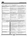
TROUBLESHOOTING
To determine any problem with your receiver, always check the most obvious possible causes first. If any problem still
remains after your have checked the items below, consult your nearest Eltax dealer.
Problem
Probable Cause
Remedy
Amplifier
When listening to the music in stereo,
left/right speakers sounds reversed.
Speakers are connected wrong.
After checking, if needed, reconnect.
Low hum or buzzer sound.
Power line of a fluorescent light is installed
near this product.
Place this product as far away as possible
from electric devices with interference.
Sound is only heard from one channel.
One of the input cords is disconnected.
Connect the input cords securely.
The BALANCE control is set to one side.
Adjust the BALANCE control.
Sound cuts off during listening to the
music or no sound even though power is
ON.
Speaker impedance is less than prescribed
for this unit.
Aft er t urning off t he power and t hen
turning it on again, reduce the volume or
change to the correct 8 ohm speakers.
No sound.
A/B Speaker selectors are turned off.
Press the A or B speaker selector as applicable.
Low bass response.
Speaker polarity (+ / ) is reversed.
Check all speakers for correct polarity.
Tuner
An unusual hissing noise is heard when
listening to the broadcast in stereo, but not
heard when listening monaurally.
A slight noise may be heard because the
method used for modulation of FM stereo
broadcasts is different than that used for
monaural broadcasts.
Noise is excessive in bot h stereo and
monaural broadcasts.
Poor locat ion and/ or direct ion of t he
antenna.
Transmitting station is too far away.
Sound is distorted and/or the volume level
becomes low.
Broadcast signals are being disturbed.
Excessive distortion in the sound of stereo
broadcasts.
Speaker syst em connect ions are not
correct.
Try reducing the treble sound by turning
the treble controls.
Try changing the location, height and/or
direction of the antenna.
Set t he FM mode t o monaural by
pressing t he STEREO/ MONO button.
(Note that the broadcast will then be
heard as monaural sound).
I f an indoor ant enna is being used,
change to an outdoor antenna.
Try using an ant enna wit h more
elements.
Surround Effects < Important :>
The center and rear speakers only operate when the unit is set on a Surround Sound mode and
the source material being played is recorded or broadcast in Dolby Digital EX, DTS/ ES, Dolby Pro LogicII
surround sound. Stereo broadcasts or recordings will produce some rear channel effects when played in a
surround mode. However, mono sources will not produce any sound from the rear speakers.
No sound from the Surround speakers.
SURROUND ON/OFF button is set to OFF.
Set the button to the desired surround
mode position.
Source being played is not recorded or
broadcast in surround sound or stereo.
Use surround or stereo source.
One or more rear speaker wires is not
making good contact.
Check all rear speaker wires for good
connection.
No sound from the center speaker.
SURROUND mode button is not set to DOLBY
DIGITAL, DTS, DOLBY PRO LOGICII or 3 STEREO.
Set the button to Dolby Digital EX, DTS/ES,
Dolby Pro LogicII or 3 STEREO.
No sound from the surround back speaker
The surround back speaker cable
connection is incomplete Surround mode
is not EX/ES mode.
Surround back = NONE has been selected
in SPEAKERS Configuration.
Connect the cable correctly.
'Short pin's not insert EQ jack
When speaker A and B is selected
Simult aneously, but speaker B is Not
connection.
Insert the 'short pin' Connect the speaker
both A and B.
The batteries are exhausted.
Replace with new batteries.
The remote control unit is too far from the
receiver or out of the effective range.
Operate the remote control unit
within the effective range.
No suond from the front speaker.
Set surround mode EX/ ES Make t he
correct setting.
Select speaker A only
Remote Control Unit
Remote control not working.
25
Specifications
Amplifier Section
AM Tuner Section
Output Power
Tuning Range:
522 kHz
Stereo Mode :
120W/ CH
(1% THD 1KHz 8ohm DIN)
Surround Mode : 92W/ CH
(1% THD 1KHz 8ohm DIN)
1,620 kHz (9 kHz steps)
Usable Sensitivity:55 dB/ m
Total Harmonic Distortion: 0.8% at 85 dB/ m
Signal-to-Noise Ratio: 45 dB at 85 dB/ m
Video Section
THD : 0.01%
Input Sensitivity/ Impedance: 1.0 Vp-p/ 75 ohms
Output Level/ Impedance: 1.0 Vp-p/ 75 ohms
DOLBY DIGITAL Mode:
Surround : 0 ~ 15 ms
Center : 0 ~ 5 ms
Back surround : 0 ~ 20 ms
General
Power Requirements:
230 V AC, 50 Hz
DOLBY PRO LOGIC Mode (Surround):
Power Consumption:
Music : 0~ 5 ms
Movie : 10~ 25 ms
Emulation : 10~ 25 ms
320W
AC Outlets:
Switched x 1, 100 W max.
Frequency Response:
* LINE: 10 Hz 70 kHz, + 1/ 3 dB
Signal-to-Noise Ratio:
* LINE: 100dB (IHF-A)
Tone Control:
Dimensions (W x H x D)
435 x 165 x 350 mm (17-1/ 8" x 6-1/ 2" x 13-3/ 4")
Weight (net):12Kg
Standard Accessories:
BASS: ± 10 dB at 100 Hz
TREBLE: ± 10 dB at 10 kHz
AM Loop Antenna x 1
FM Antenna x 1
Remote Control Unit x 1
Ower s Manual x 1
Digital Audio Section
Sampling Frequency: 32 kHz, 44.1 kHz, 48 kHz, 96 kHz
DIGITAL Input Level/ Impedance:
DIGITAL 1, 2 (OPTICAL): 15 dBm
21 dBm
DIGITAL 3 (COAXIAL): 0.5 Vp-p / 75 ohms
* LINE means CD, TAPE, VCR/ VID 1, TV/ VID 2, AUX/ VID 3 and
DVD/CD.
FM Tuner Section
(Without notes 100.1 MHz, 65 dBf)
Tuning Range:
87.5 MHz
108.0 MHz (50 kHz steps)
Usable Sensitivity (IHF):
< I mprovements may result in specifications and features
changing without notice.
< Illustrations may differ slightly from production models.
Mono: 11.2 dBf
50 dB Quieting Sensitivity:
Mono: 15.3 dBf
Stereo: 38.5 dBf
Capture Ratio:2.0 dB
Image Rejection Ratio: 45 dB
AM Suppression Ratio: 55 dB
Total Harmonic Distortion (1 kHz):
Mono: 0.2%
Stereo: 0.3%
Frequency Response:30 Hz 15 kHz, + 1/ 1.5 dB
Stereo Separation (1 kHz): 40 dB
Signal-to-Noise Ratio:
Mono: 70 dB
Stereo: 65 dB
26