1
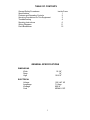
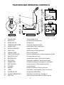
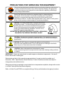
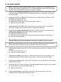
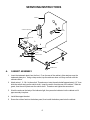
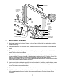
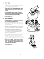
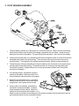
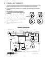
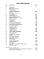
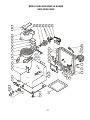
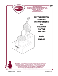
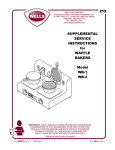
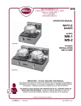
211
WELLS MANUFACTURING COMPANY
2 ERIK CIRCLE, P. O. Box 280
Verdi, NV 89439
Customer Service (775) 345-0444 Ext.502
fax: (775) 345-0569
www.wellsbloomfield.com
SERVICE
INSTRUCTIONS
for
BELGIAN
WAFFLE
BAKERS
Model
BWB-1S
IMPORTANT: WELLS MFG. PROPRIETARY INFORMATION
TECHNICAL CONTENT OF THIS MANUAL IS DESIGNED FOR
USE BY QUALIFIED PROFESSIONAL TECHNICIANS ONLY
Part No. 502972 Rev. A
S211 111000 cps
GENERAL SAFETY PROCEDURES
Knowledge of proper procedures is essential to the safe operation of electrically energized
equipment. In accordance with generally accepted product safety labeling guidelines for
potential hazards, the following signal words and symbols are used throughout this manual.
DANGER
DANGER - Danger is used to indicate the presence of a hazard which will
cause severe personal injury, death, or substantial property damage in the
event the statement is ignored.
WARNING - Warning is used to indicate the presence of a hazard which can cause
personal injury and possibly death, or major property damage, in the event the statement is ignored.
CAUTION - Caution is used to indicate the presence of a hazard which will or can
cause minor personal injury, or property damage in the event the statement is ignored.
CAUTION - Used to indicate the presence of an electrical hazard which will or can
cause personal injury, or property damage in the event the statement is ignored.
NOTE - Note is used to notify personnel of installation, operation or maintenance information which is important, but not hazard related.
WAFFLE BAKER PRECAUTIONS
AND GENERAL INFORMATION
1.
This waffle baker is intended for use to bake food products for human consumption. No other use is
recommended or authorized by the manufacturer or its agents.
2.
Service technicians must be familiar with the appliance use, limitations and associated hazards.
Operating instructions and warnings must be read and understood by all service personnel.
3.
This piece of equipment is made in the USA and has American sizes on hardware.
4.
This manual supplements the Installation, Operation and Maintenance (IOM) manual p/n 45257 for
this equipment. Refer to the IOM for normal operational procedures. Any trouble shooting guides,
component views, wiring diagrams or parts lists included in this manual are intended for use by
qualified technical personnel only.
xi
TABLE OF CONTENTS
General Safety Procedures
Specifications
Features and Operating Controls
Servicing Precautions for This Equipment
Troubleshooting
Servicing Instructions
Wiring Diagrams
Parts Breakdown
Inside Cover
1
2
3
4
6
11
12
GENERAL SPECIFICATIONS
DIMENSIONS
Wide
Deep
High
10-1/8”
14”
10-9/16”
ELECTRICAL
Voltage
Amperage
Wattage
Cord
120 VAC 1Ø
7.5 Amp
900 W
NEMA 5-15P
1
FEATURES AND OPERATING CONTROLS
17
BACK VIEW
48
19
9
43
3
2
4
1
5
.1
6
20
73
40
42
39
16
10
28
18
47
27
75
48
66
8
41
BOTTOM GRID
RIGHT SIDE VIEW
INTERIOR VIEW
wiring cover removed
shown in “open”position
back panel removed
8.
POWER CORD
115VAC NEMA 5-15P
9.
DATA PLATE
Specifies power requirements
10.
MICRO SWITCH
Initiates timer
16.
TEMPERATURE PROBE
Thermistor temperature sensor
17.
HANDLE ASSY
Used to raise / lower / rotate grids
18.
SUPPORT BRACKET
Supports front of grids
19.
HOLE PLUG
Allows access to timer adjustment
20.
WIRING COVER
Protect wiring in grids
27.
TEMP. CONTROLLER
In concert with thermistor, controls temperature of grids
28.
INDICATOR LIGHT
Lit during timed cook cycle
39.
BEARING ASSY
Supports back of grids; allows grids to rotate
40.
PIVOT ASSY
Holds grids in alignment; allows grids to rotate
41.
RUBBER FEET
Provide necessary non-slip support for waffle baker
42.
BOTTOM GRID
Cooking element; holds temperature probe
43.
TOP GRID
Cooking element
47.
BUZZER
Sounds momentarily at end of cook cycle
48.
TIMER
Audio alarm - warns operator of end of cook cycle
66.
POWER SWITCH
Energizes the Waffle Baker
(73.)
(HI-LIMIT THERMOSTAT)
Eliminated on later models. See page 11.
75.
DRIP TRAY
Catches excess waffle batter for easier clean-up
2
PRECAUTIONS FOR SERVICING THIS EQUIPMENT
Disconnect electrical power to equipment prior to performing cleaning or other service.
In order to avoid electrical shock, injury and/or equipment damage, use appropriate
precautions whenever electrical power must be restored for adjusting, calibrating or
taking voltage measurements.
Ensure that input power matches the nameplate data for voltage and phase.
Input power circuit must meet or exceed the nameplate power requirements.
Equipment is equipped with the proper electrical plug for the specific power
requirements of the unit. DO NOT alter the power cord or plug. Never cut off a ground
prong, or twist a prong, to allow the plug to fit an existing receptacle.
CAUTION: This Wells Waffle Baker is equipped with a threeprong electrical plug. The three-prong plug is part of a system
that will protect you in the event of an electrical wiring failure.
Be sure the three-prong plug is plugged into a matching and
properly grounded three-prong receptacle. DO NOT cut or
break off the ground prong of this plug.
OPERATING AN APPLIANCE WITHOUT PROPER GROUNDING
CAN RESULT IN SERIOUS PERSONAL INJURY
GROUND
PRONG
CAUTION: Test electrical receptacle for proper polarity. For the safety of personnel,
it is important that electrical ground and electrical neutral are maintained as designed
by the factory.
CAUTION: DO NOT plug in or energize this appliance until Installation
Instructions are read and followed. Injury to the operator and damage to the Waffle
Baker may occur if these instructions are not followed.
CAUTION: Never submerge electrical equipment in water.
Avoid contaminating electrical components with water when cleaning cooking surfaces
or cabinet.
IMPORTANT: Never use a wire brush or metal scraper on aluminum components. Use a soft
bristle, fiber brush to clean grids.
Data sheets and text in this manual are representative of current production models as of
November, 2000. Specifications, Model Numbers, Product Numbers and data are subject to
change at any time without notice.
Whenever servicing is required to correct electrical or temperature complaints, always refer service
to a Wells Factory Authorized Service Agency.
Refer to Wells Form #37000 for a complete listing of factory authorized service agency locations.
3
TROUBLE SHOOTING
CAUTION: ELECTRIC SHOCK HAZARD
Live electrical circuits are exposed
during troubleshooting procedures
CAUTION: BURN HAZARD
Equipment surfaces will be hot
during troubleshooting procedures
B. TEMPERATURE CHECKS
1.
Desired baking temperature is 390ºF ±5ºF (200ºC ±3ºC).
2.
Turn the power switch ON and allow the Waffle Baker to heat for
a minimum of 30 minutes. Insert a pyrometer of known accuracy
betwen the grids and allow the readings to stabilize.
3.
390ºF
CALIBRATION
POINT
Temperature may be adjusted by removing the back panel,
and turning the dial on the temp controller:
CW to decrease temperature; CCW to increase temperature.
NOTE: Manufacturer’s calibration point (390ºF) is indicated by a black dot on the face of the dial.
A. ELECTRICAL TEST POINTS
TP1
TP2
TP3
TP4
ELEMENT / GRID
bottom shown - top similar
TEMPERATURE CONTROLLER
test points are terminals
TIMER MODULE
test points are terminals
B. AMPERAGE AND RESISTANCE CHECKS
1.
Amperage may be checked with an inductive amperage tester (Amprobe™ or similar) by encircling
wire #4 at temperature controller terminal 2. Total amperage is 7.5 Amps with the waffle baker in
the pre-heat mode.
2.
The heating element is integral with the Grid casting.
Disconnect wire #7 to #8 from temperature controller to check resistance of both grids at once.
Resistance from # 7 to #8 is 16Ω (cold) ± 1Ω. A reading of 32.0Ω indicates one defective element
or a broken element jumper wire.
Data for one element: 450 Watts, 3.8 Amps
Resistance of one element TP1 to TP2, (wires disconnected) is 32.0Ω (cold) ± 1Ω.
4
D. VOLTAGE CHECKS
NOTE: Resistance of the temperature probe is typically 5 megohm at room temperature, with
resistance decreasing as temperature rises. A shorted temperature probe will cause a runaway
condition, and an open probe will cause a continuous OFF condition.
1.
Voltage between temperature controller terminals 2 & 3 will be 120V any time the power switch
(item 66) is turned ON. Absence of 120V indicates power switch OFF or defective, or a wiring or
connector problem.
2.
Voltage between TP1 and TP2 will be 120V when the unit is calling for heat. Absence of 120V,
when heating is required, indicates:
a.) Power switch defective or OFF; or,
b.) Temperature controller defective or open temperature probe; or,
c.) Wiring or connector problem
3.
Voltage between TP1 and TP2 will be 120V when the unit is calling for heat. Failure to heat
when 120V is present indicates that the element being tested is defective.
4.
Voltage between temperature controller terminals 1 & 3 will be 120V when the thermostat is
calling for heat. Absence of 120V, when heating is required, indicates:
a.) Power switch defective or OFF; or,
b.) Temperature controller defective, or
c.) Shorted temperature probe or probe wiring shorted (check between terminals 4 & 5); or,
d.) Wiring or connector problem
5.
TP3 and TP4 are found only on waffle bakers equipped with a hi-limit thermostat. The hi-limit
thermostat should be removed and bypassed to increase the reliability of the waffle baker.
NOTE: Newer waffle bakers do not use a hi-limit thermostat. Existing hi-limit thermostats may
be safely removed and bypassed without affecting the UL approval. See page 11.
6.
Voltage between timer terminals 2 & 3 is 120V any time the power switch is ON. Absence of 120V
indicates:
a.) power switch defective or OFF; or,
b.) a wiring or connector problem
7.
Voltage between timer terminals 5 & 6 is 0V when the microswitch (item 10) is activated. Any
voltage other than 0V indicates a defective microswitch, or a wiring or connector problem.
8.
Voltage between timer terminals 1 & 2 is 120V during the cook cycle. Absence of 120V indicates
a defective timer module.
9.
An indicator light NOT lit when reading a voltage between timer terminals 1 & 2 is 120V indicates:
a.) loose or defective wiring to the indicator light; or,
b.) defective indicator light
10.
Voltage between timer terminals 2 & 4 is momentarily 120V at the end of the cook cycle.
Absence of 120V indicates a defective timer module.
5
SERVICING INSTRUCTIONS
CABINET
SEAL
SUPPORT BRACKET
INDICATOR
TRADEMARK PLATE
RETAINER
SWITCH
SEAL
GUARD
ON/OFF PLATE
BOTTOM
PANEL
RUBBER FOOT
A.
CABINET ASSEMBLY
1.
Insert the trademark plate from the front. From the rear of the cabinet, slide retainers over the
trademark plate pins. Using a deep socket, tap the retainers down until they are flush with the
cabinet surface.
2.
Attach wires 1, 2, 3 & 4 to the switch. Thread one nut onto the switch shaft approximately 1/2”, then
slide the switch seal over the switch shaft. Insert the switch from the rear of the cabinet. Slide the
guard, then the on/off plate over the switch shaft. Thread on and tighten the second nut.
3.
Work the seal over the body of the indicator light, then press the indicator into the cabinet until it
pops securely into place.
4.
Install the support bracket.
5.
Screw four rubber feet into the bottom panel, then install the bottom panel onto the cabinet.
6
HOLE PLUG
ASSEMBLY
ALL GROUND
WIRES
CONNECT TO
THIS STUD
BUZZER
POWER
CORD
STRAIN
RELIEF
THERMAL
MASTIC
HEAT SINK
BACK
PANEL
B.
TIMER
FOAM
TAPE
TIMER BRACKET
PC BOARD STANDOFF
TEMPERATURE
CONTROLLER
ADJUSTMENT
MODULE
BACK PANEL ASSEMBLY
1.
Apply foam tape to the back panel flange - inside surfaces for the right, left and bottom; outside
surface for the top.
2.
Insert the power cord into the strain relief, then install the strain relief from the outside of the back
panel.
3.
From the outside, thread the ground wire of the hole plug assembly thru the large hole in the back
panel. Tap the hole plug into place.
4.
Press the adjustment module onto pin 6 of the temperature controller and secure it with a dab of
silicone sealant. Press the wire lead of the adjustment module onto pin 2. Coat both faces of the
heat sink with thermal mastic (heat transfer compound). Slide the heat sink, then the
temperature controller over the stud closest to the data plate embossing. The adjustment module
should be oriented down and toward the outside.
5.
Insert four printed circuit board standoffs into the timer bracket. Push them until the button head is
flush against the inside surface. Slide the bracket over the stud closest to the large hole, then
secure with two screws from the bottom.
6.
Slide the buzzer over the same stud as the timer bracket.
7.
Lightly thread the nut onto the stud to retain the buzzer. Upon wiring the unit, after all ground wires
have been attached to this stud, tighten the nut securely to ensure a positive chassis ground
connection.
7
C.
TOP GRID
1.
Prepare grid casting by applying a small amount of
anti-sieze paste to all threaded holes.
2.
Feed wires 5, 6 & 20 thru the right feed-thru hole.
Attach wires 5 & 6 to the element terminals. Attach
wire 20 to the center-most boss at the front of the
casting.
3.
Pull the wires back until they have only a small
amount of slack. Seal both sides of both feed-thru
holes with hi-temperature silicone sealant.
4.
Install the grid cover.
D.
BOTTOM GRID
1.
Prepare grid casting by applying a small amount of
anti-sieze paste to all threaded holes.
2.
Set the grids waffle-side down, and with the rear
portions touching. This positions the grids properly
for later assembly.
3.
Feed the temperature probe leads and wire 10 thru
the hi-temp tubing, then thru the left feed-thru hole.
4.
Feed wires 5, 6, & 20 (from top grid) and wires
7 & 8 thru the right feed-thru hole. Attach wires
5 & 8 to one element terminal, and wires 6 & 7
to the other element terminal.
5.
6.
7.
Set the temperature probe between the two screw
bosseswith its round nose pointing to the right.
Slide the retainer over the probe. Install the screws
with wires 10 & 20 attached to the center-most screw
boss.
Route wires as shown. Pull the wires and hi-temp
tubing back until they have only a small amount of
slack. Seal both sides of both feed-thru holes with
hi-temperaturesilicone sealant.
see page 11
8
5
HITEMP
TUBING
7
6
20
10
TEMP
PROBE
Install the grid cover.
PROBE
RETAINER
GRID
8
E.
GRID ASSEMBLY
1.
Turn and position the grids so that the waffle-sides are facing each other. Thread the hi-temp tubing
thru the shaft of the pivot housing. Attach the pivot housing to the bottom grid with screws (bottom
hole) and screws with washers (middle hole). Use anti-sieze paste on the screw threads, but do
not tighten the screws yet.
2.
Insert the pivot shaft thru the pivot housing and top
grid, making sure wires 5, 6 & 20 are routed between
the pivot shaft and the body of the top grid casting.
Secure the pivot shaft with “C”clips on each end.
3.
Verify that the top and bottom grids match at the
mating surfaces, then tighten the screws securing
the pivot housing to the bottom grid.
4.
Thread the brass bushing over hi-temp tubing and the
shaft of the pivot housing. Press the bushing all the
way against the face of the pivot housing.
5.
Install the handle asembly in the top grid. Use
Loctite on the screw threads
6.
Install the top grid wiring cover, then the teflon drip
guide and bottom grid wiring cover. Use anti-sieze
paste on the screw threads.
7.
The top grid should pivot smoothly. Gently bend the
upper lip of the bottom grid wiring cover until the gap
between wiring covers is maintained thru the entire
swing of the top grid, and the top grid closes
completely on the bottom grid.
HANDLE
ASSEMBLY
TOP GRID HINGE
WIRING COVER
BOTTOM GRID HINGE
WIRING COVER
9
TEFLON DRIP GUIDE
F. PIVOT BEARING ASSEMBLY
1.
The pivot bearing may be out of alignment as it comes from the box. Tap the collar of the bearing
with a plastic hammer until the axis of the bearing is perpendicular to the base. Attach the pivot
bearing to the inside of the cabinet. The zerk fitting points downward. Use Loctite on the threads.
2.
Looking into the back panel, turn the bearing until the set screws are at the 10:00 and 2:00 position.
Assemble the actuator to the pivot bearing. The set screws will protrude thru the holes on the
actuator halves. The long arm of the actuator should point down, with the screws pointing left.
3.
Thread the wires of the grid assembly thru the pivot bearing from the outside, then insert the pivot
housing shaft into the pivot bearing. Thread the actuator nut on the pivot housing shaft using
Loctite on the threads. Tighten the pivot nut until the grid assembly rotates freely, but latches
securely into the detent.
4.
If not already present, assemble the support
bracket to the cabinet. Make sure the front of
the grid assembly rides smoothly in the support.
4.
Rotate the grid assembly to the COOK position.
Make sure the long arm of the actuator points
straight down, then tighten the set screws.
5.
Using Loctite on the threads, assemble the
microswitch to the switch saddle. Install the
switch assembly into the cabinet. Adjust the
position of the microswitch until a single CLICK is
heard from the microswitch as the long arm of the actuator contacts the microswitch arm and the
grid assembly rotates into the cook position detent.
10
G.
BYPASS HI-LIMIT THERMOSTAT
1.
The hi-limit thermostat in this Belgian Waffle Baker has been found to be unnecessary. Wells
BWB-1S has been tested and approved by UL for use without the hi-limit thermosat.
2.
All units requiring service, whether in or out of warranty, should have the hi-limit thermostat
bypassed.
3.
With the power cord unplugged, remove wires
7 & 19 from the hi-limit thermostat (located in the
bottom grid).
7
7
19
19
Cut the push-on terminals from wires 7 & 19, as
close to the terminals as possible.
HI-LIMIT
THERMOSTAT
5.
Remove 1/2”of insulation from the ends of wires
7 & 19. Connect the wires together using a ceramic
wire nut of the appropriate size.
6.
Plug the waffle baker in, and test for proper
operation.
CERAMIC
WIRE NUT
WIRING DIAGRAM
CONNECTOR (2)
POWER
SWITCH
L2
2
green
TEMPERATURE
CONTROLLER
3
10
3
black
4
L1
1
2
white
4
5
1
4.
7
17
8
POWER CORD
INDICATOR
LIGHT
LOWER
HEATING
ELEMENT
TEMP.
SENSOR
TIMER
20
11
1
2
3
4
5
6
13
6
14
5
MICRO
SWITCH
BUZZER
N.C.
COM
15
16
N.O.
9
VOLTS AMPS 1Ø
120
7.5
50/60 Hz
UPPER
HEATING
ELEMENT
p/n 44867 Rev.D
11
12
PARTS BREAKDOWN
REF
#
1
2
3
5
6
7
8
9
10
12
15
16
17
18
19
20
21
22
23
24
25
27
28
31
32
39
40
41
42
43
44
45
46
47
48
50
62
64
65
66
67
75
76
77
78
79
DESCRIPTION
PART
#
BOTTOM PANEL
BACK PANEL
WRAP, CABINET ASSEMBLY
SWITCH SADDLE
TRADEMARK PLATE
RETAINER, TRADEMARK (pk 10)
CORD, 125v 15a NEMA 5-15p
DATA PLATE
SWITCH MICRO 120V 15A
STRAIN RELIEF
RETAINER RING (pk 10)
PROBE, THERMISTOR, BWB-1S
HANDLE ASSY BWB-1S
BRACKET, FRONT SUPPORT BWB-1S
HOLE PLUG ASSY
COVER, BWB-1S
ACTUATOR
SPACER, BWB-1S
PIN PIVOT UPPER HINGE, BWB-1S
COVER, WIRING, UPPER BWB-1S
COVER, WIRING, LOWER BWB-1S
CONTROLLER,TEMPERATURE BWB-1S
LIGHT, INDICATOR RED
POP RIVET, 1/16 1/8
SLEEVING, HI-TEMP (8.5")
BEARING, BWB-1S
HOUSING ASSY, PIVOT
RUBBER FEET, (pk 4)
GRID & ELEMENT, LOWER BWB-1S
GRID & ELEMENT, UPPER BWB-1S
NUT, PIVOT HOUSING
TIMER BRACKET
STANDOFF, PC BOARD BWB-1S
BUZZER
TIMER, ELECTRONIC, BWB-1S
LABEL, DO NOT IMMERSE
SEAL, O-RING, SIGNAL LIGHT
ON-OFF PLATE
SWITCH GUARD
SWITCH, TOGGLE W/SEAL
HOLDER, PROBE BWB-1S
DRIP TRAY, BWB-1S
FOAM TAPE
HEAT TRANSFER COMPOUND (THERMAL MASTIC)
HEAT SINK
TEFLON DRIP GUIDE
NOT SHOWN:
WIRING DIAGRAM BWB-1S
WIRESET BWB-1S (OVER HEATED OR RUNAWAY TEMP DAMAGE)
ELEMENT JUMPER WIRESET ONLY
12
51038
55539
64887
51217
50222
64872
62257
62028
61064
62029
62035
62018
62023
62031
64276
60758
64201
62232
62006
21657
62007
62008
63565
60529
63179
64890
53192
64904
64885
21107
66160
502900
503523
44876
64917
502863
BWB-1S BELGIAN WAFFLE BAKER
EXPLODED VIEW
32
20
39
22
21
44
5
10
67
16
42
79
25
19
24
40
43
23
17
15
2
12
76
8
47
50
45
48
20
31
18
9
3
62
28
7
76
46
27
77
6
65
64
66
1
75
41
13
78
IMPORTANT: WELLS MFG. PROPRIETARY INFORMATION
TECHNICAL CONTENT OF THIS MANUAL IS DESIGNED FOR
USE BY QUALIFIED PROFESSIONAL TECHNICIANS ONLY
WELLS MANUFACTURING COMPANY
2 ERIK CIRCLE, P. O. Box 280
Verdi, NV 89439
Service Parts Dept. (888) 492-2782
fax: (888) 492-2783
[email protected]