1
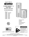
MAAG
Series
Twelve
ELECTRIC
WATE R HEATER
USER'S GUIDE
Model
Numbers
_0°_
HE21250S
HE31250S
HE21250T
HE31250T
HE21282T
HE31282T
®
LISTED
FOR POTABLE WATER
HEATING ONLY
Io 11
electric water heaters with capacities of 20 to
120 Gallons. Input rating of 12 Kw or less at a
applies
to all residential
voltage certification
no greater than
250 V.
AWARNING
COVER AND THEN THIS ENTIRE MANUAL BEFORE INSTALLING OR
READ THE GENERAL
SAFETY
SECTION BEGINNING ON INSIDE
OPERATING
THIS WATER
HEATER.
Save this Manual
for Future
Reference.
NOT
SUITABLE
FOR
SPACEHEATING
J
Caution:
Read and Follow All
I
Operating Instructions
Safety
andof
Before Rules
First Use
This Product.
Safety Instructions
_WARNING
AWARNING
Improper installation, adjustment, alteration, service
or maintenance can cause DEATH, SERIOUS BODILY
INJURY, OR PROPERTY DAMAGE. Refer to this manual for assistance consult your local utility or call
Maytac_ Customer Service at %800-788-8899 for an
authorized servicer for further information,
At the time of manufacture this water heater was provided with a combination tamperature-pressures relief
valve certified by a nationally recognized testing laboratory that maintains periodic inspection of production
of listed equipment or materials, as meeting the
requirements for Relief Valves and Automatic Gas I
Shutoff Devices for Hot Water Supply Systems, and I
the latest edition of ANSI Z21.22 and the code require- I
ments of ASME. If replaced, the valve must meet the J
requirements of local codes, but not lessthan a combination temperature and pressure relief valve certified
as meeting the requirements for Relief Valves and
Automatic Gas Shutoff Devices for Hot Water Supply
iystems, ANSI Z21.22 b_/a nationally recognized testng laboratory that maintains periodic inspection of
_roduction of listed equipment or materials.
the valve must be marked with a maximum set pres- I
sure not to exceed the marked hydrostatic working
)ressure of the water heater (150 Ibs./sq. in.) and a ]
lischarge capacity not less than the water heater [
nput rate as shown on the model rating plate, I
iElectricheaters - watts divided by 1000 x 3415 equal I
3TU/Hr. rate.)
[
Your local jurisdictional authority, while mandating the
use of a temperature-pressure relief valve complying
with ANSI Z21.22 and ASME, may require a valve model
different from the one furnished with the water heater,
Compliance with such local requirements must be satisfied by the installer or end user of the water heater
with a locally prescribed temperature-pressure relief
valve installed in the designated opening in the water
heater in place of the factory furnished valve.
For safe operation of the water heater, the relief valve
must not be removed from it's designated opening or
plugged.
The temperature-pressure
relief valve must be
installed directly into the fitting of the water heater
designated for the relief valve. Position the valve
downward and provide tubing so that any discharge
will exit only within 6 inches above, or at any distance
below the structural floor. Be certain that no contact is
AWARNING
HAZARD OF ELECTRICAL SHOCK! Before removing
any access panels or servicing the water heater,
make sure the electrical supply to the water heater
is turned "OFF". Failure to do this could result in
DEATH, SERIOUS BODILY INJURY, OR PROPERTY
DAMAGE.
AWARNING
]
HOTTER WATER CAN SCALD: Water heaters are|
intended to produce hot water. Water heated to a|
temperature
which will satisfy clothes washing,[
dish washing, and other sanitizing needs can scald|
and permanently injure you upon contact, Some/
people are more likely to be permanently injured by
hot water than others, These include the elderly,
children, the infirm, or physically/mentally
handicapped. If anyone using hot water in your home fits
into one of these groups or if there is a local code or
state law requiring a certain temperature water at
the hot water tap, then you must take special precautions. In addition to usmcj the lowest possible
temperature settingthat
satisfies your hot water
needs, a means such as a mixing valve, should be
used at the hot water taps used by these people or
at the water heater. Mixing valves are available at
plumbing supply or hardware stores. Follow manufacturers instructions for installation of the valves,
Before changing the factory setting on the thermostat, read the "_remperature Regulation" section in
this manual,
AWARNING
made with any live electrical pert, The discharge openmg must not be blocked or reduced in size under any
circumstances. Excessivelength, over 30 feet, or use of
more than four elbows can cause restriction and
reduce the discharge capacity of the valve.
No valve or other obstruction is to be placed between
the re ief vave and the tank Do not connect tubing
directly to discharge drain unless a 6" air gap is provid- t
ed. To prevent bodily injury, hazard to life, or property
damage, the re ief valve must be a owed to discharge
water in quantities should circumstances demand. If !
the discharge pipe is not connected to a drain or other
suitable means, the water flow may cause property
damage.
The Discharge Pipe:
Must notbe smaller in size than the outlet pipe size
of the valve, or have any reducing couplings or
other restrictions,
Must not be plugged or blocked.
Must be of material listed for hot water distribution,
Must be installed so as to allow complete drainage
of both the temperature-pressure relief valve, and
the discharge pipe.
Must terminate at an adequate drain.
I
INSULATING JACKETS: When installing an external
water heater insulation jacket on an electric water
heater:
• DO NOT cover the temperature-pressure relief valve,
• DO NOT put insulation over the access covers or
any access areas,
• DO NOT cover or remove operating instructions,
and safety related warning labels and materials
affixed to the water heater,
AWARNING
i
I
Do not use this appliance if any part of it has been
under water. An electrical short or malfunction could
occur. The water heater should be replaced.
2
Must
not have any valve between
and tank.
the relief valve
Safety Instructions (cont'd)
_,WARNING
]
WATER HEATERS_OR
ONE VOLTAGE/
ONLY: This water heater is equipped for one type /
voltage only. Check the rating plate near the bot-|
tom access panel for the correct voltage. DO NOTI
use this water heater with any voltage other than I
the one shown on the model rating plate. Failure to
use the correct voltage can cause problems which I
can result in DEATH, SERIOUS BODILY INJURY, OR I
PROPERTY DAMAGE. If you have any questions or J
doubts consult your electric company.
ACAUTION
WATER HEATERS EVENTUALLY LEAK: Installation of
the water heater must be accomplished in such a
manner that if the tank or any connections should
leak, the flow of water will not cause damage to the
structure. For this reason, it is not advisable to install
the water heater in an attic or upper floor. When
such locations cannot be avoided, a suitable drain
pan should be installed under the water heater.
Drain pans are available at your local hardware
store. Such a drain pan must have a minimum diameter of at least 1% inches greater than the water
heater diameter and must be piped to an adequate
drain. Under no circumstances is the manufacturer or
Maytag to be held liable for any water damage in
connection with this water heater.
J
Table of Contents
Safety Instructions .............................................................................................
2-3
Table of Contents ...............................................................................................
4
Customer Information .......................................................................
..............................................
s
Product Specifications .......................................................................................
s
Accessories and Tools Needed .........................................................................
6
Accessories ............................................................................................................................................................................
6
Tools .....................................................................................................................................................................................
6
Instructions for Installation ..............................................................................
7-16
Removing the Old Water Heater ..........................................................................................................................................
Locating the New Water Heater ..........................................................................................................................................
Typical Installation ................................................................................................................................................................
The Convertible Lower Element ..........................................................................................................................................
Water Piping .......................................................................................................................................................................
Temperature-Pressure Relief Valve .....................................................................................................................................
Filling the Water Heater .....................................................................................................................................................
Converting the Lower Element .....................................................................................................................................
Wiring Diagrams ................................................................................................................................................................
Wiring ................................................................................................................................................................................
Installation Checklist ..........................................................................................................................................................
7
8
8
9
10
11
12
12-14
15
16
17
Service and Maintenance .................................................................................
18-23
Temperature Regulation ......................................................................................................................................................
Thermos tats ........................................................................................................................................................................
Thermostat Settings ............................................................................................................................................................
Thermostat Adjustment ......................................................................................................................................................
Temperature-Pressure Relief Valve Operation ....................................................................................................................
Draining ..............................................................................................................................................................................
Element Cleaning and Replacement .............................................................................................................................
Drain Valve Washer Replacement ......................................................................................................................................
Service .................................................................................................................................................................................
Troubleshooting
18
18
18
19
19
20
20-23
23
23
......................................................................................................................................
Start Up Conditions ............................................................................................................................................................
Thermal Expansion ........................................................................................................................................................
Strange Sounds ...............................................................................................................................................................
Operational Conditions ......................................................................................................................................................
Smelly Water ..................................................................................................................................................................
Air in Hot Water Faucets ...............................................................................................................................................
24-26
24
24
24
24
24
24
Rumbling Noise .............................................................................................................................................................
High Temperature Shut Off System ........................................................................................................................
Not Enough Hot Water .................................................................................................................................................
Water is Too Hot ...........................................................................................................................................................
24
24, 25
25
25
Leakage Checkpoints .....................................................................................................................................................
26
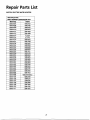
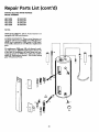
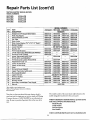
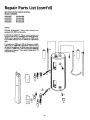
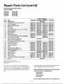
Repair Parts List .................................................................................................
28-31
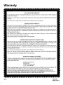
Warranty ..............................................................................................................
32
4
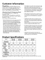
Customer Information
Thank You for purchasing
a Maytag water heater.
Properly installed and maintained, it should give you years of
trouble free service. It is strongly suggested that this new
° The installation must conform with the instructions in this
manual; electric company rules; and Local Codes, or in the
absence of Local Codes, with the latest edition of the
National Electrical Code. This publication is available from
water heater be professionally installed, call Maytag Customer
Service at 1-800-788-8899 for recommended installers,
Abbreviations
Found
In This
Instruction
your local government or punic library or electric company
or by writing Underwriters Laboratories, 333 Pfingsten
Manual
Road, Northbrook, IL 60062.
U.L.- Underwriters Laboratories, 333 Pfingsten Rd.,
Northbrook, IL 60062
National Electrical Code-This
• If after reading this manual you have any questions or do
publication is available from
not understand a W portion of the instructions, call Maytag
Customer Service at 1-800-788-8899 for an authorized
servicer.
your local government or public library or electric company or
by writing to U.L. above.
ANSI-American National Standards Institute
• Carefully plan the place where you are going to put the
• Read the "Safety Instructions" section, pages 2 and 3 of this
water heater. Correct electrical wiring and connections are
very important in preventing death from possible electrical
shock and fires.
manual first and then the entire manual carefully. If you
don't follow the safety rules, the water heater will not operate properly. It could cause DEATH, SERIOUS BODILY
INJURY AND/OR PROPERTY DAMAGE.
Examine the location to ensure the water heater complies
with the "Locating the New Water Heater" section.
This manual contains instructions for the installation, operation, and maintenance of this electric water heater. It also
• For California installation this water heater must be braced,
anchored, or strapped to avoid falling or moving during an
contains warnings throughout the manual that you must
read and be aware o£ All warnings and all instructions are
earthquake. See instructions for correct installation proce-
essential to the proper operation of the water heater and
dures. Instructions may be obtained from the California
office of the State Architect, 400 P Street, Sacramento, CA
95814.
your safety. Since we cannot put everything on the first few
pages, READ THIS ENTIRE MANUAL BEFORE
ATTEMPTING
TO INSTALL OR OPERATE THE
WATER HEATER.
• Massachusetts Code requires this water heater to be
installed in accordance with Massachusetts 248-CMR 2.00:
State Plumbing Code and 248-CMR 5.00.
Product Specifications
Model
HE21240S
HE31240S
Tank Capacity
In Gal (Liters)
Element
Wattage
Upper
HE21250S
HE31250S
HE21250T
HE31250T
HE21282T
HE31282T
40
50
50
80
3800
3800
3800
3800
.,240voi,
Lower
3800
155003800
15 003800
I
Recovery Rate
In Gals
Per Hr.
@ 90OFRise
Upper
Lower
17.3
17.3
17.3
25
17.3
38®
I 5500
17.3
25
17.3
17.3
25
17.3
25
Diameter
22"
24"
22"
26.25"
Height
Maximum Fuse or
Circuit Breaker Size
48.5"
48"
58.5"
62"
20
30
20
30
20
30
20
30
Minimum
Wire Size (Gauge)
12
10
12
10
12
10
12
10
•Wiring size based on standard 60°C copper wire. If dlstance from fuse box to water heater is more than 90 feet, refer to your local
electrical code.
5
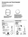
Accessories and Tools Needed
Accessories
To simplify the installation Maytag has available the installation parts shown below. You may or may not need all of these
accessories depending on your type of installation. Call
Maytag Customer Service at 1-800-788-8899 for an authorized installer.
DRAIN PANS AVAILABLE IN 22" DIAMETER
EXPANSION TANKS FOR THERMAL EXPANSION
CONDITIONS AVAILABLE IN 2 GALLON (PART
NUMBER 66001013) AND S GALLON (PART
NUMBER 66001014) CAPACITY
(PART NUMBER 66001011) FOR WATER
HEATERS HAVING A DIAMETER 20 _ OR LESS,
24" DIAMETER (PART NUMBER 66001105) FOR
WATER HEATERS HAVING A DIAMETER 22" OR
LESS AND AVAILABLE IN 28" DIAMETER (PART
NUMBER 66001012) FOR WATER HEATERS
HAVING A DIAMETER 26.2S" OR LESS
TOOLS
ADDITIONAL TOOLS NEEDED
WHEN SWEAT SOLDERING
You may or may not need all of these tools, depending on your
ty_0eof installation. These tools can be purchased at your local
lVtaytag store.
•
•
•
•
•
•
•
•
•
•
•
•
Pipe Wrenches (2) 14"
Screwdriver
6 Foot Tape of Folding Rule
Garden Hose
Drill
Pipe dope or Teflon Tape
Tubing Cutters or Hacksaw
Propane Torch
Soft Solder
Solder Flux
Emery Cloth
Wire Brushes
6 FOOT TAPE
GARDEN HOSE
3/4" WIRE BRUSH
-_
SLOT-HEAD SCREW DRIVER
PIPE
WRENCH
1/2" WIRE BRUSH
PHILLIPS SCREWDRIVER
PROPANE TORCH
(SOUEEZETUBE,
PIPEDOPE
ROLL OF TEFLON TAPE
(Use only on water connections)
ROLLOELEADEREE
SO SOLOER
DRILL
ROLL OF EMERY
CLOTH
6
SOLDER FLUX
TUBING CUTTER
Installation Instructions
Removing the Old Water Heater
Turn "OFF" electrical supply to the water heater.
(_
a.
If you have copper piping tO the water heater, the two
copper water pipes can be cut with a hacksaw approxithe water heater. This will avoid cutting off the pipes
too short. Additional cuts can be made later if necessary. Disconnect the temperature-pressure relief valve
drain line. When the water heater is drained, disconnect the hose from the drain valve. Close the drain
valve. The water heater is now completely disconnected
and ready
to be removed.
mately
four inches
away from where they connect to
@__
@
Turn
the
water "OFF"
heater atthe
thewater
water supply
shutoff tovalve
or water meter.
,
]_ @
_,_=
I ]
Attach a hose to the water heater drain
valve and put the other end in a floor
_[_-- --- I_
('_)b.
If you have galvanized pipe to the water
heater drain valve. Open a nearby hot
water
which will
relieve
drain faucet
or outdoors.
Open
thepressure
water
in the water heater and speed draining,
U
_
with a pipe wrench at the union in each
line.
disconnect
piping remainheater,Also
loosen
the twothegalvanized
pipes
ing to the water heater. These pieces
should be saved since they may be needed
Disconnect
the temperature-pressure
relief valve drain line. When the water
heater is drained, disconnect the hose
from the drain valve. Close the drain
valve.
water heater
nowwater
completely
when The
reconnecting
the is
new
heater.
__
II'-
valve may
avoid being
connections
water flow
any person.
- [[
be extremely
hot. To
scalded, make sure all
are tight and that the
is directed away from
disconnected and ready to be removed.
,_
Check again to make sure the electrical supply is turned
"OFF" to the water heater. Then disconnect the electriThe water _'passingWARNINGout
of the drain
__1
t1__
cal supply connection from the water heater junction
box.
Mineral buildup or sediment may have accumulated ]
in the old water heater. This causes the water /
residue, if spilled out, could cause staining.
]
heater to be much heavier than normal and this|
__1_._
7
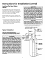
Instructions for Installation (cont'd)
Locating The New Water
Heater
_CAUTION
WATER HEATERS EVENTUALLY LEAK: Installation of
the water heater must be accomplished in such a
manner that if the tank or any connections
should
_leak, the flow of water will not cause damage to the
structure. For this reason, it is not advisable to install
the water heater in an attic or upper floor. When
such locations cannot be avoided, a suitab e drain
pan should be installed under the water heater.
I DraJn pans are available at your local hardware
store. Such a drain pan must have a minimum diameter of at least 13/4 inches greater than the water
heater diameter and must be piped to an adequate
drain. Under no circumstances is the manufacturer or
[ Maytag to be held liable for any water damage in
connection with this water heater.
Yon should carefully choose an indoor location for the new
water heater, because the placement is a very important considerafion for the safety of the occupantsin the building and
for the most economical use of the appliance. This water
heater is not intended for outdoor installation,
Whether replacing an old water heater or putting the water
heater in a new location, the following critical points must be
observed.
1. The location selected should be indoors as close to and as
A CAUTION
centralized with the water piping system as possible. This
water heater, as well as all water heaters, will eventually
leak, Do not install without adequatedrainage provisions
where water flow will cause damage,
INSTALLATIONIN RESIDENTIAL GARAGES: The water ]
heater must be located and/or protected so it is not I
subject to phys ca damage by a mov ng veh cle.
]
2. The location selection must provide adequate clearances for
servicing and proper operation of the water heater.
VACUUMRELIEF
REQUIRED
BYSOMECODES
(REFER
TOLOCALCODES)_
_
SHUTOFF
VALVE
COLDWATERINLET
CHECK ALL CONNECTIONS FOR LEAKS.
CONSULT THE LOCAL UTILITY COMPANY TO EXAMTypical
_nstaHation
INE INSTALLATION FOR PROPRIETY AND SAFETY.
HOTTER WATER CAN SCALD: Water heaters are
intended to produce hot water. Water heated to a
temperature
which will satisfy clothes washing,
dish permanently
washing, and injure
other sanitizing
can Some
scald
and
you upon needs
contact.
people are more likely to be permanently injured by
hot water than others. These include the elderly,
children, the infirm, or physically/mentally
handicapped. If anyone using hot water in your home fits
into one of these groups or if there is a local code or
state law requiring a certain temperature water at
the hot water tap, then you must take special precautions. In addition to using the lowest possible
temperature settingthat
satisfies your hot water
needs, a means such as a mixing valve, should be
used at the hot water taps used by these people or
at the water heater. Mixing valves are available at
_alUmbing supply or hardware stores, Follow manucturers instructions for installation of the valves.
Before changing the factory setting on the thermostat, read the "q'emperature Regulation" section in
this manual.
_TLWT_
_
_
TEMPERED\_'i_'/'
WATER _
OUTLET*MIXINGVALVE
PIPEINSULATION
/
ELBOW
_
_/_
_
I-
_,,_q_
_
_
Ill
,
_=_
[
_
.L_-
,
_/"
_/
_
I'
PIPEINSULATION
_i
TEMPERATUREPRESSURE
RELIEF
VALVE
I
i
,
I
8
_
--
DISCHARGE
PIPE
(Donot
plug) capor
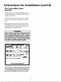
Instructions for Installation (cont'd)
The Convertible
Element
Lower
The Upper Element, is a conventional 3800 watt element
which only operates at its rated wattage on 240 volts. (See rating plate on water heater).
The Lower Element of the water heater can be converted
from operation at 3800 watts to 5500 watts on a 240 volt
system.
Read and follow water heater warnings and instructions.If
after reading these instructions in this manual, if you do not
understand any portion, call Maytag Customer Service at 1800-788-8899 for an authorized servicer.
&,WARNING
Before making the conversion to 5500 watts, check
the (1) power supply...must
be 240 volts,.(2)
wiring...10 gauge AWG @ Type TW, 60°C or equtvalent, and (3) Circuit breakers or fusing...capable of
30 amp loading. Also, the installation must conform
with this manual, local codes and electric utility
rules. Failure to comply can result in DEATH, SERIOUS BODILY INJURY, OR PROPERTY DAMAGE.
® Maytag is a Trademarkof MaytagCorporatiooand
is used under Uconse to State Indusb_ies,Inc
NOTE: Whether or not the element conversion is made the
model rating plate must be marked. Using a hard point ink
pen, check the appropriate block within the model rating
plate, which is located adjacent to the lower access panel.
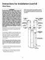
Instructions for Installation (cont'd)
Water Piping
A WARNING
NOTE:Yourwaterheateris superinsulatedto minimize
HOTTER WATER CAN SCALD: Water heaters
a re
intended to produce hot water. Water heated to a
temperature
which will satisfy clothes washing,
dish washing, and other sanitizing needs can scald
and permanently injure you upon contact. Some
people are more likely to be permanently injured by
not water than others. These include the elderly,
children, the infirm, or physically/mentally
handicapped. If anyone using hot water in your home fits
into one of these groups or if there is a local code or
state law requiring a certain temperature water at
the hot water tap, then you must take special p.re-
heat loss from the tank. Further reduction in heat loss can
be accomplished by insulating the hot waterlines from the
water heater.
HOTOUTLET
TO
HOUSE
cautions. In addition to usincj the lowest possible
needs, a means such as a mixing valve, should be
'_
temperaturesettingthatsat,sfiesyourhotwater
at the water heater. Mixing valves are available at
plumbing supply or hardware stores. Follow manutacturers instructions for installation of the valves.
Before changing the factory setting on the thermoused at the hot water
taps used by these
people
or
stat,
read the "Temperature
Regulation" section
in
this manual.
I1_]
_-_
SWEATCOU--
PiPE
_
THREADED_T
INSULATION
J
[_
NIPPLE
_
I_'-_
_>_----_
[_
I I THREADEDTO
( _EAT
I
I_
314"THREADED
the
heater. shows
The water
heater is equipped
with piping
% inchto
The water
illustration
the attachment
of' the water
water
SHUT-OFF COLDINLET
VALVE _
WATERLINE
I
[
_
_
I
[
_
I_
_--
COUPUNG
_ PIPE
INSULATION
3/4"THREADED
_
conncctions.
NIPPLE
"_-]-
If a water heater is installed in a closed water supply system;
such as one having a back-flow preventer, check valve, water
meter with a check valve, etc. in the cold water supply;
means shall be provided to control thermal expansion.
Contact the local utility or call Maytag Customer Service at
1-800-788-8899 for an authorized servicer on how to control this situation.
-
r_
j/PRESSURE
TEMPERATURERELIEF
VALVE
'5
--DISCHARGE PIPE
(Do not cap or plug)
NOTE: If using copper tubing, solder tubing to an adapter
before attaching the adaptor to the cold water inlet connection. Do not solder the cold water supply line directly to the
cold water inlet. It will harm the dip tube and damage the
tank.
'
1. Look at the top cover of the water heater. The water outlet
is marked hot. Connect the hot water pipe to the hot water
outlet of the water heater.
--
_'_
2, Look at the top cover of the water heater. The cold water
inlet is marked cold. Connect the cold water pipe to the
cold water inlet of the water heater.
10
_
"AIR
FLOOR DRAIN
GAP
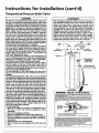
Instructions for Installation (cont'd)
Temperature-Pressure
Relief Valve
•,WARNING
_, WARNING
At the time of manufacture this water heater was provided with a combination temperature-pressuresrelief valve
certified by a nationally recognizedtesting laboratory that
maintains periodic inspectton of production of listed
equipment or materials, as meeting the requirements for
Relief Valves and Automatic Gas Shutoff Devicesfor Hot
Water Supply Systems. and the latest edition of ANSI
Z21.22 and the code requirements of ASME. If replaced.
the valve must meet the requirements of local codes, but
not less than a combination temperature and pressure
relief valve certified as meeting the requirements for
Relief Valves and Automatic Gas Shutoff Devicesfor Hot
Water Supply Systems.ANSI Z21.22 by a nationally recog-
The temperature-pressure relief valve must be manually operated at least once a year. Caution should be
taken to ensure that (1) no one is in front of or
around the outlet of the temperature-pressuro relief
valve discharge line. and (2) the water manually discharged will not cause any bodily injury or property
damage because the water may be extremely hot.
If after manually operating the valve, it fails to completely reset and continues to release water, immediateiy close the cold water inlet to the water heater.
follow the draining instructions, and replace the
temperature-pressure relief valve with a new one.
HOT
)__T
"
_
PIPE_
INSULATION
of production of listed equipment or materials.
The valve must be marked with a maximum set pressure
nized
laboratory
that
maintainsperiodicpressureof
inspection
not
totesting
exceedthe
marked
hydrostaticworking
the water heater (150 Ibs./sq. in.) and a dischargecapacity
not lessthan the water heater input rate as shown on the
model rating plate. (Electric heaters - watts divided by
1000 x 3415 equal BTU/Hr.rate.)
Your local jurisdictional authority, while mandating the
useof a temperature-pressure relief valve complying with
ANSI Z21.22 and ASME. may require a valve model different from the one furnished with the water heater.
Compliancewith suchlocal requirements must foesatisfied
by the installer or end user of the water heater with a
locally prescribed temperature-pressure relief valve
installed in the designated opening in the water heater in
placeof the factory furnished valve.
For safe operation of the water heater, the relief valve
must not be removed from it's designated opening or
plugged.
The temperature-pressure relief valve must be installed
directly into the fitting of the water heater designatedfor
the relief valve. Positionthe valve downward and provide
tubing so that any dischargewill exit only within 6 inches
above, or at any distance below the structural floor. Be
certain that no contact is made with any live electrical
to
life, or property damage,
the
SHUT-OFF
__
_
_
-- PIPE
INSULATION
_
CONDUIT
I
]
_
/TEMPERATURE-PRESSURE
RELIEF
VALVE
¢-- DISCHARGE
PIPE
_(Do notcapor plug)
(
part. The
discharge
opening
must notExcessive
be blocked
or
r_luced
in size
under any
circumstances.
length,
over 30 feet, or use of more than four elbows can cause
restriction and reducethe dischargecapacity of the valve.
No valve or other obstruction is to be placed between the
relief valve and the tank. Do not connecttubing directly to
discharge drain unless a 6" air gap is provided. To prevent
bodilyinjury,hazard
COLD
_
_
_
_
FLOOR
DRAIN
]
6'_AIRGAP
r
ml
WARNING
"RELIEF VALVE OPENING"
T_._ _._o_._T_P_
for RelCfVak_s andAutoma_c
Gas ShUtOff
DevicesforHot_v_
WaterSupPlySy_i_s_,_1
andlt_codereo_rementsofASME,
Ibe sta_
relief
._
22
Yo_ANSI_
localunsctct_w,aJ
122 andASME,may
_
wr_lerna_Ung
requirearave rnc_
_ useof
dC_ferent
aTer_ture-Pressule
trc_nthe c_efurnished
ReliefVaIW
wilhthe water
complying
heate_
valve must be allowed to discharge water in quantities
should circumstances demand. If the dischargepipe is not
connected to a drain or other suitable means, the water
flow may causeproperty damage.
C_rn_ianc_i1hsuch_a_r_qu_rementsr_ustbes_tis_edby1be_ta_re
a
locallypcescribedTerrperature-Pressure
Relief VaJveinsialJedin the bes_g
hatedopeningi_ 1hewater
_r
TANK,
%', _" JACKET
TANK
FnT_G
• l-
BRASS
COUPLING
VALVE PROBE
MUST EXTEND
• Must notbe smaller in size than the outlet pipe size of
theDischargePipe:
valve, or have any reducing couplings or other
The
restrictions.
• Must not be plugged or blocked.
• Must be of material listedfor hot water distribution.
• iust
be installed so as to allow cornplete drainage of
both the temperature-pressure relief valve, and the discharge pipe.
• Must terminate at an adequate drain,
• Must not have any valve between the relief valve and
INTO TANK
T&P RELIEF
TEMPERATUREPRESSURE
i_, _t
'
SHANK
_
[_ _ _GTH
RELIEF VALVE
_i&_
• If a short shank (Jessthan 2') temperature-pressurereliefvalve is to be instated
(as
shown),a
nippleand
coupling
mustbeused
• if a longs_lank(2" or longer) is to be installed,do not usethe nippleand coupling.
",r,_ Temperatule-Pressure
Temperalure.Pressure
protective
equipment
required
by localcodes,
b_t notlessthan
a combination
Relief
Valve
Cedriiedas
meetingthe
requbemenlS
for Relief Valves
and
A_o_=_ Gas ShttoffDevicesforHot-Wat0rSupplySystems,AN_ Z2_22 bya nJt_nallyrecognLzed
test-
must
be
c_ented.pmv_edwi_tubing,
or0the_iseinstabeds01hatdischa_ecan
ex_onFf
wii_in
6incbes
above,
ofatanydlstancebdowtbestrdcturaJflcot,
a_dcannotcontactanyflveei_icalpa,."
For safe0bera_n of thewsle_heater,b_eReliefVaJvemustnotbe lem0vedorp_u ed.
See manual heading- "Ternperatule-Pr
e_sure Relief Valve"for installabonan_gmeaintenance
of Relief
VaJv_,discharge
pipeandothersafetywecautJ0ns
tank,
11
Instructions for Installation (cont'd)
Filling the Water Heater
To fill the water heater with water:
_k
WARNING
1. Close the water heater drain valve by turning the handle to
the right (clockwise). The drain valve is on the lower front
of the water heater,
Before making the conversion to 5500 watts, check
the (1) power
supply..,
must be 240 volts, .(2)
wiring..,10 gauge AWG @ Type TW, 600C or eqmva-
2. Open the cold water supply valve to the water heater,
NOTE:Thecoldwatersupplyvalvemustbeleftopen
when the water heater is in use.
lent,
andloading.
(3) Circuit
or fusing...capable
of
30 amp
Also,breakers
the installation
must conform
with this manual, local codes and electric utility
rules. Failure to comply can result in DEATH, SERI-
3. To insure complete fdling of the tank, allow air to exit by
OUS BODILY INJURY, OR PROPERTY DAMAGE.
opening the nearest hot water faucet. Allow water to run
until a constant flow is obtained. This wiU let air out of the
water heater and the piping.
&CAUTION
Never use this water heater unless it is completely
full of water. To prevent damage to the tank and
heating element, the tank must be filled with I
water. Water must flow from the hot water faucet
before turn ng "ON" power.
_
_
=_=u= _,_
o_mEml_#l
4. Check all new water piping for leaks. Repair as needed,
immuca_
Converting the Lower
Element
®Maytag,s,TradQmarkofMaytagCorpoca_c_and
is used u_ck3r
uc_n_e to Sta_ IndUsti_es,
Inc.
These instructions only cover the conversion of the convert-
NOTE: Whether or not the element conversion is made the
ible element, read this entire manual before attempting to
install or operate the water heater. The water heater is factory
set to operate at 3800 watts. The lower element can be convetted to operate at 5500 watts. Refer to "The Convertible
model rating plate must be marked. Using a hard point ink
pen, check the appropriate block within the model rating
plate, which is located adjacent to the lower access panel.
Lower Element" section.
Necessary element conversion parts are located in a small bag
contained within the large plastic manual envelope attached
to the side of the water heater.
The Upper Element is a conventional 3800 watt element
which only operates at its rated wattage on 240 volts. (See rating plate on water heater).
CONVERSION
PARTS
The Lower Element of the water heater can be converted
from operation at 3800 watts to 5500 watts on a 240 volt sys-
/_
If after reading these instructions and this manual, if you do
tern.
not understand any portion, call Maytag Customer Service at
1-800-788-8899 for an authorized servicer.
BUSSBAR
12
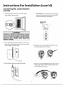
Instructions for Installation
Converting
(cont'd)
l.
(cont'd)
the Lower Element
Before beginning the conversion turn "OFF" electric
power supply to the water heater,
4.
Lower Element: Lift out the tab as shown to unclip the
terminal cover from the thermostat. The terminal cover
can now be removed from the thermostat.
i
'm
_WARNING
%
G
HAZARD OF ELECTRICAL SHOCK! Before removing
any access panels or servicing the water heater,
make sure the electrical supply to the water heater
is turned "OFF". FAILURE TO DO THIS COULD
RESULT IN DEATH, SERIOUS BODILY INJURY, OR
PROPERTY DAMAGE.
_'_
2. The convertible element is located behind the lower access
panel of the water heater. Remove the two screws securing
the access panel, and remove panel.
5. Remove the screws from terminal 2 of the element, and
move the looped end of the wire aside.
3. Open the flap of insulation to expose the opening.
6. The buss bar is labeled 5500 W. Place the buss bar over terminals 2 and 3 with the 5500 W visible, Install the extra
_
screw provided into terminal 3.
OI
13
Instructions for Installation (cont'd)
Converting
(cont'd)
the Lower Element
7. The wire removed from terminal 2 has a looped end. It
must remain looped and now be placed (as shown) on top
11. Replace the access panel.
of
the the
bussremaining
bar, over the
opening of terminal 2, and secured
using
screw.
_
8. Tighten terminals 2 and 3 to ensure proper electrical connection.
_1[
__
_i
12. Complete wiring to the water heater, or if completed, turn
"ON" elech'ic power to the water heater after filling the
_WARNING
Failure to tighten terminal screws can cause a fire I
which can result in DEATH. SERIOUS BODILY INJURY,
OR PROPERTY DAMAGE.
tank with water,
9. Replace terminal cover on thermostat and fold insulation
back over the element making sure that the locking tabs on
the terminal cover are in place.
AWARNING
Make sure the thermostat is flush against the tank, I
the terminal cover is in place, and the insulation is I
replaced. Failure to do so can result in DEATH, SERIOUS BOD LY NJURY, OR PROPERTY DAMAGE.
_, CAUTION
J
Never use this water heater unless it is completely I
full of water. To prevent damage to the tank and I
heating element, the tank must be filled with water, [
10. Fold the insulation back in place so that it completely coyers the thermostat and element,
turning
"ON" flow
power.
Water must
from the hot water faucet before
14
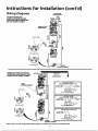
Instructions for Installation (cont'd)
Wiring
Diagrams
,oELE_R,C
POWER SUPPLY
STANDARD
2
WIRE LEADWIRING
WATER FOR
HEATERS
BLACK
NON-SIMULTANEOUS
OPERATION
240VOLTDOUBLE
ELEMENT
r
, .__
D
[
SS BAR_
ELEMENT
_=_
FOR 5500 WATFS
f_
UPPER
= eJ
FOR 3800 WATTS
WIRING FOR 3 WIRE LEAD WATER
HEATERSNON-SIMULTANEOUS
OPERATION 240 VOLT DOUBLE ELEMENT
LOWER
YELLOW
--
THREETYPES
OF FIELD
CONNECTIONS
YOU MAY HAVE
1.
UPPER
HEATING ELEMENT
TO ELECTRIC•
_
POWERSUPPLY L1 L2 L2 L2
YELLO
'W_:LA
BUSSBAR
2.
__
-OFF PEAK.METER
OPERATES
BOTTOMELEMENTONLY
TO ELECTRIC
L1 L2-'_TO "OFF PEAK
BOX
YELLO
_
3.
___
FOR3800WATTS_l_llml_
switches
_
m_y have
CK
_Ol TWO WIRE CONNECTION
TO ELECTRIC. t
POWERSUPPLY kl
*Note:Some LowerHi-Temp L'xn_t
TO TIME
CLOCKSWITCH
CK
NCT'ON
x
FORSS00WATTS
U
lIME CLOCXswmtcH
OPERATES
BOTTOMELEMENTONLY
POWERSUPPLY'_'I
_'EllO J_J
LOWER
HEATING ELEMENT
Ii2
L2'
4terminals. Useonly the 2tem_inalson left.
15
NCTION
BoxMETER
JW_BLA
cKNCTIONBox
Instructions for Installation (cont'd)
Wiring
A CAUTION
C. Flexible metal conduit or 3 metallic tubing shall be per-
Never use this water heater unless it is completely
full of water. To prevent damage to the tank and
heating element, the tank must be filled with
water. Water must flow from the hot water faucet
before turning on power.
mitred for grounding if all the following conditions are
met:
1. The length in any ground return path doesnot exceed
6 feet.
2. The circuit conductors contained therein are protected
by overcurrent devices rated at 20 amperes or less.
3. The conduit or tubing is terminated in fittings
approved for grounding.
For complete grounding details and all allowable exceptions,
refer to the latest edition of the National Electrical Code.
You must provide all wiring of the proper size outside of the
water heater. You must obey local codes and electric company
requirements when you install this wiring.
If you are not familiar with electric codes and practices, or if
you have any doubt, even the slightest doubt, in your ability to
connect the wiring to this water heater, obtain the service of a
4. A standard 1/2"conduit opening has been made in the water
heater junction box for the conduit connection.
competent electrician. Call Maytag Customer Service at
1-800-788-8899 for an authorized servicer,
5. Wiring Diagrams (See "Wiring Diagrams" Section) have
been supplied showing the two most common types of connections between the water heater and the power supply.
A WARNING
YOUcan easily see which type connection you have by
removing the junction box cover on top of the water heater.
A. TwoWire Connection Diagrams: is the most common
WATER
HEATERS
EQUIPPED
FOR ONE
ONLY: This
water heater
is equipped
for VOLTAGE
one type
voltage only. Check the rating plate near the bottom access panel for the correct voltage. DO NOT
use this water heater with any voltage other than
the one shown on the model rating plate. Failure to
use the correct voltage can cause problems which
can result in DEATH, SERIOUS BODILY INJURY, OR
PROPERTY DAMAGE. If you have any questions or
doubts consult your electric company,
requiring you to simply connect red to red, black to black,
and the ground wire to the green ground screwin thejunction box of the water heater.
B. Three Wire Connection Diagram: is used when you are
connecting the water heater to power a
"Time Clock" or "OffPeak" Meter. To
tions refer to block 1 or 2 in this wiring
of system you have.
NOTE: If you have purchased a three
& CAUTION
If wiring from your fuse box or circuit breaker box
was aluminum for your old water beater, replace it
with copper wire. If you wish to reuse the existing
aluminum wire, have the connection at the water
heater made by a competent
electrician.
Call
Maytac_ Customer Service at 1-800-788-8899 for an
authortzed servicer.
wire connection
water heater but you are not on a"Time Clock" or"Off
Peak" meter and have a standard two wire connection
power supply, simply follow the connection diagram in
block 3 of the Three Wire Connection Diagram.
6. Use wire nuts and connect the power supply wiring to the
wires inside the water heater's junction box,
1. Provide a way to easily shut offthe electric power when
working on the water heater. This could be with a circuit
breaker or fuse block in the entrance box or a separate disconnect switch,
7, The water heater must be electrically "grounded" by the
installer. A green ground screw has been provided on the
water heater's junction box. Connect ground wire to this
location.
2. Install and connect a circuit directly from the main fuse or
circuit breaker box. This circuit must be the right size and
have its own fuse or circuit breaker. Refer to the chart in
8. Replace the wiring junction cover using the screw provided.
the "Product Specifications" section for the correct size
_
wire and fuse or circuit breaker.
3. If metal conduit is used for the grounding conductor:
aluminum, or copperclad aluminum. The material shall
be of one continuous length without a splice or joint.
B. Rigid metal conduit, intermediate metal conduit, or
electrical metallic tubing may be used for the grounding
means if conduit or tubing is terminated in fittings
A. The grourtding electrode conductor shall be of copper,
approved for grounding.
supply that has a
make these connecdiagram for the type
/
_,h
CONDUIT _
16
_65GR_
WIRF_'-.._
7"rS
/
_x
_
Instructions for Installation (cont'd)
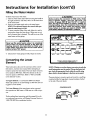
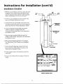
Installation
1. Whether
Checklist
or not the element conversion is made, the model
HOT
rating
plateappropriate
must be marked.
Using the
a hard
point
ink pen,
check the
block within
model
rating
plate,
which is located adjacent to the lower access panel.
___._[_
.
_
COLD
2. Is the fuse or circuit breaker size correct as shown in the
chart in the "Product Specifications" section?
CONDUIT _
v
3. Are the wires from the circuit breaker or fuse service to the
water heater's junction box on the correct wire size (gauge) as
J_
TEMPERATUREPRE!;URE
RELIEI
_
J
_
shown in the chart in the "Product Specifications" section?
q
/
4. Is the new temperature-pressure relief valve properly
installed, and piped to an adequate drain? See
"Temperature-Pressure Refief Valve" in the "Instructions
--DISCHARG
(Donot c Ip or
for Installation" section,
plug
5. Is the water heater completely fdled with water? See
"Filling the Water Heater" instructions in the "Instructions
for Installation" section.
6. Will a water leak damage anything? See "Locating the
/
New Water Heater" in the "Instructions for Installation"
section.
[
- ['-'6"AIRG¢
_
i
7. Are the cold and hot water fines connected to the water
heater correctly? See "Water Piping" instructions in the
"Instructions for Installation" section.
x_ _"
_
r
_
FLOORDRAIN
8. Is there adequate clearance for maintenance around the
water heater?
m ogwmwcm_
9. Do you need to call your electric company to check your
,_,,_,_
wiring?
ELEC'FRIC
WATERHEATER
_
_
(_
I
]
I
I I I
® Maytsgis a Tr=:bonerk of_
ksusedI_
L_
to S_
Co'potation and
Irl_str k_, Inc
MODEL RATING PLATE
17
_o
Ik1"rAl.LE¢
Service and Maintenance
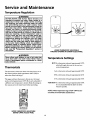
Temperature
Regulation
AWARNING
HOTTER WATER CAN SCALD: Water heaters are
intended to produce hot water. Water heated to a
temperature
which will satisfy clothes washing,
dish washing, and other sanitizing needs can scald
ind permanently injure you upon contact. Some
people are more likely to be permanently injured by
lOt water than others. These include the elderly,
children, the infirm, or physically/mentally
handi-.
capped. If anyone using hot water in your home fits
into one of these groups or if there is a local code or I
state law requiring a certain temperature water at I
the hot water tap, then you must take special pre- I
cautions. In addition to using the lowest possible
temperature setting that satisfies your hot water I
needs, a means such as a mixing valve, should be I
used at the hot water taps used by these people or
at the water heater. Mixing valves are available at
_alumbing supply or hardware stores. Follow manucturers instructions for installation of the valves.
Before changing the factory setting on the thermostat, read the "Temperature Regulation" section in
this manual.
@
_
^_
_
/
ne
_/
LOWER THERMOSTAT ADJUSTABLE
THROUGH OPENING IN LOWER ACCESS PANEL
_,WARNING
Never allow small children to use a hot water tap,
or to draw their own bath water. Never leave a
child or handicapped person unattended in a bathtub or shower.
C
4-_-" N
,=mt,=raLure eL,nus
HOT-Is a thermostat setting of approximately 120°F,
which will supply hot water at the most eco-
Thermostats
nomical temperatures.
The thermostats of this water heater have been factory set at
their lowest position which approximates 120°F (Hot) to
reduce the risk of scald injury.
A-Is a thermostat setting of approximately 130°F.
The upper and lower thermostat is factory set at its lowest
position which approximates 120°F (Hot) and is adjustable if
a different water temperature is desired. Read all warnings in
C-Is a thermostat
B-Is a thermostat setting of approximately 140°E
VERY HOT-Is
this manual and on the water heater before proceeding.
setting of approximately 150°E
a thermostat setting of approximately 160°E
It is recommended that the dial be set lower
whenever possible.
NOTE: Water temperature range of 120°-140°F recommended by most dishwasher manufacturers.
UPPER THERMOSTAT ADJUSTABLE
BEHIND UPPER ACCESS PANEL
18
Service and Maintenance
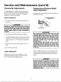
Thermostat
Adjustments
(cont'd)
Temperature-Pressure
Valve Operation
If the upper thermostat is adjusted above the factory preset
point of 1200F (Hot), it cannot be set higher than the lower
The temperature-pressure
ated at least once a year.
thermostat setting. Read all warnings in the "Temperature
Regulation" section before proceeding.
Relief
relief valve must be manually oper-
UPPER THERMOSTAT
/TEMPERATURE-PRESSURE
•
1. Turn "OFF" the electric power to the water heater at the
junction box.
/
/
_
RELIEF
VALVE
__
AWARNING
HAZARD OF ELECTRICAL SHOCK! Before removin(
any access panels or servicing the water heater
make sure the electrical supply to the water heate
is turned "OFF". Failure to do this could result in
DEATH, SERIOUS BODILY INJURY, OR PROPERTY
DISCHARGE
PIPE
DAMAGE,
AWARNING
The temperature-pressure
relief valve must be
manually operatedat
least once a year. Caution
should be taken to ensure that (1) no one is in front
of or around the outlet of the temperature-pressure relief valve discharge line, and (2) the water
manually discharged will not cause any property
damage
or bodi y njury The water may be
extremely hot.
'
If after manually operating the valve, it fails to
completely reset and continues to release water,
immediately close the cold water inlet to the water
heater, follow the draining
instructions,
and
replace the temperature-pressure
relief valve with
a new one.
2. Take offthe access panel and fold away the insulation.
3. The slotted adjustment (using a screwdriver) can be turned
clockwise (/'_"0
to increase the temperature setting or
counter clockwise
setting,
(¢f_
to decrease the temperature
4. Fold the insulation back in place and replace the access
panel,
5. Turn "ON" the power supply,
LOWER THERMOSTAT
Failure to install and maintain a new properly listed temperature-pressure relief valve will release the manufacturer from
The adjustment dial can be turned clockwise (_)
to
increase the temperature setting or counter clockwise
(_"_)
to decrease the temperature setting.
any claim which might result from excessive temperature
pressure.
AWARNING
or
]
If the temperature-pressure
relief valve on the
appliance weeps or discharges periodically, this[
may be due to thermal expansion.
Your water I
heater may have a check valve installed in the
water line or a water meter with a check valve. Call [
Maytacj Customer Service at 1-800-788-8899 for an F
authorized servicer. Do not plug the temperaturepressure relief valve.
19
I
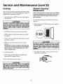
Service and Maintenance
Draining
(cont'd)
Element
Cleaning/
B
RI
_
nep,acement
The water heater should be drained if being shut down during
freezing temperatures. Also periodic draining and cleaning of
sediment from the tank may be necessary,
NOTE: These insttnctions are written for element cleaning
and element replacement for the lower element. If it is neeessary to dean or replace the upper element, then repeat
these instructions.
1. Before beginning turn "OFF" the electric power supply to
the water heater.
To remove the element from your tank in order to clean or
a_ WARNING
replace it:
HAZARD OF ELECTRICAL SHOCK! Before removing
any access panels or servicing the water heater,
make sure the electrical supply to the water heater
is turned "OFF". Failure to do this could result in
1, Before beginning turn "OFF" the electric power supply to
the water heater.
DEATH, SERIOUS BODILY INJURY, OR PROPERTY
DAMAGE.
2. CLOSE the cold water inlet valve to the water heater.
3. OPEN a nearby hot water faucet and leave open to allow
for draining.
4. Connect a hose to the drain valve and terminate to an adequate drain or outdoors.
A WARNING
HAZARD OF ELECTRICAL SHOCK! Before removing !
any access panels or servicing the water heater,
make sure the electrical supply to the water heater
IS turned "OFF". Failure to do this could result in
DEATH, SERIOUS BODILY INJURY, OR PROPERTY
DAMAGE.
5. OPEN the water heater drain valve to allow for tank
draining,
NOTE: If the water heater is going to be shut down and
drainad for an extended period, the drain valve should be
left open with hose connected allowing water to termihate to an adequate drain.
6. Close the drain valve.
2. Turn offthe water supply to the water heater at the water
shutoffvalve or water meter.
7. Follow "Filling the Water Heater" instructions in the
Instructions for Installation section.
8. Turn "ON" power to the water heater.
A CAUTION
Never use this water heater unless it is completely
full water, To prevent damage to the tank and heating element, the tank must be filled with water.
Water must flow from the hot water faucet before
turning "ON" power.
I
2O
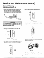
Service and Maintenance (cont'd)
Element Cleaning/
Replacement (cont'd)
3. Attach a hose to the water heater drain valve and put the
6. Open the flap of insulation to expose the opening.
other end in a floor drain or outdoors. Open the water
heater drain valve. Open a nearby hot water faucet which
will relieve pressure in the water heater and speed draining.
•,WARNING
II
IlJ
_
[
The water passing out of the drain valve may be
extremely
hot. To avoid I_ingscalded,
make sure all [
connections are tight and that the water flow is
7. Lift out the tab as shown to unclip the terminal cover from
the thermostat. The terminal cover can now be removed from
the thermostat.
directed away from any person,
4. Remove the two screws securing the access panel, and
remove panel.
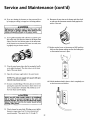
8. Disconnect the two wires on the element and unscrew the
old element from the tank.
5. After you have removed the lower access panel, remove the
adjustment dial from the thermostat by gently pulling it
directly away from the thermostat.
/
_
Q
_Po__
"_0_*'
9.
21
Clean the area around the element opening. Remove any
sediment from or around the element opening and inside
the tank.
Service and Maintenance (cont'd)
10. If you are cleaning the element you have removed, do so
16. Reconnect the two wires to the element and then check
by scraping or soaking in vinegar or a de-liming solution,
to make sure the thermostat remains firmly against the
surface of the tank.
Replacement elements must (1) be the same voltage and (2) no greater wattage than listed on the
model rating plate affixed to the water heater.
11. A new gasket should be used in all cases to prevent a possible water leak. (See Element Gasket in the Repair Parts
Chart). Place the new element gasket on the thread side
of the cleaned or new
•,WARNING
element and screw into tank, secur-
I
[_
ing tightly using an element wrench.
17. Replace terminal cover on thermostat and fold insulation
on the terminal cover are in place.
back over the element making sure that the locking tabs
12. Close the water heater drain valve by turning the handle
Q
to the right (clockwise). The drain valve is on the lower
front of the water heater.
T,._,
13. Open the cold water supply valve to the water heater.
NOTE: The cold water supply valve must be left open
when the water heater is in use.
18. Fold the insulation back in place so that it completely cov14. To insure complete filling of the tank, allow air to exit by
opening the nearest hot water faucet. Allow water to run
until a constant flow is obtained. This will let air out of
ers the thermostat and element.
the water heater and the piping.
OI
CAUTION
_j
Never use this water heater unless it is completely
full of water. To prevent damage to the tank and
heating element, the tank must be filled with water,
Water must flow from the hot water faucet before
turning nON" power.
_-_
15. Check element for water leaks. If leakage occurs, tighten
element or repeat steps 2 and 3, remove element and
reposition gasket. Then repeat steps 11 through 15.
_.-_._.
22
Service and Maintenance (cont'd)
Element Cleaning/
Replacement
(cont'd)
Drain Valve Washer
Replacement
19. The adjustment dial has a "D" shaped opening that match-
NOTE:
es a "D" shaped shaft on the thermostat. Align the opening
in the dial to the shaft and gently push the dial onto the
shaft.
For replacement, use a v/,,x 13/_"x 1/8'!thickwasher
available at your nearest hardware store. For ordering a
replacement washer, refer to the "Repair Parts" section.
1. Before beginning turn "OFF" the electrical power supply
_f_
to the water heater.
_WARNING
HAZARD OF ELECTRICAL SHOCK! Before removing
any access panels or servicing the water heater,
Q
make
the electrical
supply
to theORwater
heater
DEATH,sure
SERIOUS
BODILY
INJURY,
PROPERTY
is turned "OFF". Failure to do this could result in
DAMAGE.
_
2. Follow "Draining" instructions in the "Service and
ro ¢IKI_
_*_
Maintenance" section.
3. Turning counter clockwise, remove the hex cap below the
screw handle.
20. Replace access panel.
4. Remove the washer and put the new one in place.
21. Turn "ON" electric power to water heater.
5. Screw the handle and cap assembly back into the drain
valve and retighten using a wrench. DO NOT OVER
TIGHTEN.
"Instructions for Installation" section.
7. Check for leaks.
!
8. Turn "ON" electric power to the water heater.
HA.OLEA.O
CAP ASSEMBW
_
WASHER
Service
Before calling for repair service, read the "Start Up
Conditions" and "Operational Conditions" found in the
"Troubleshooting" section of this manual.
Ifa condition persists or you are uncertain about the operation of the water heater, let a qualified person check it out.
Call Maytag Customer Service at 1-800-788-8899.
23
Troubleshooting
Start Up Conditions
THERMAL
EXPANSION
Smelly water may be eliminated or reduced in some water heater
models by replacing the anode(s) with one of less active material,
and then chlorinating the water heater tank and all hot water
lines. Call Mayrag Customer Service at 1-800-788-8899 for an
authorized servicer for further information concerning an Anode
Replacement Kit #66001068 and this Chlorination Treatment.
Water supply systems may, because of such events as high line
pressure, frequent cut-offs, the effects of water hammer
among others, have installed devices such as pressure reducing
valves, check valves, back flow preventers, etc...to control
these types of problems. When these devices are not equipped
with an internal by-pass, and no other measures are taken, the
devices cause the water system to be closed. As water is heated, it expands (thermal expansion) and closed systems do not
allow for the expansion of heated water,
If the smelly water persists after the anode replacement and chlorination treatment, we can only suggest that continuous chlorination and fdteting conditioning equipment be considered to eliminate the water problem.
The water within the water heater tank expands as it is heated
and increases the pressure of the water system. If the relieving
point of the water heater's temperature-pressure relief valve is
Do not remove the anode leaving the tank unprotected. By
doing so, all warranty on the water heater tank is voided.
reached,thevalvewillrelievetheexcesspressure.Thetemper-
"AIR"IN HOT WATER FAUCETS
ature-pressure relief valve is not intended for the constant
A WARNING
refiefofthermal expansion. This is an unacceptable condition
and must be corrected.
HYDROGEN GAS: Hydrogen gas can be produced in
a hot water system that has not been used for a
long period of time (generally two weeks or more).
Hydrogen gas is extremely flammable and explosive. To prevent the possib_ity of injury under these
conditions, we recommend the hot water faucet be
opened for several minutes at the kitchen sink
before any electrical appliances which are connected to the hot water system are used (such as a dishwasher or washing machine). If hydrogen gas is present, there will probably be an unusual sound similar to air escaping through the pipe as the hot
water faucet is opened. There must be no smoking
or open flame near the faucet at the time it is open.
It is recommended that any devices installed which could create
a closed system, have a by-pass and/or the system have an
expansion tank to relieve the pressure built by thermal expansion in the water system. Expansion tanks are available for
ordering through the Maytag Customer Service. Contact the
local water supplier and/or call Maytag Customer Service at
1-800-788-8899 for an authorized servicer for assistance in
controlling these situations,
STRANGE SOUNDS
RUMBLING
Possible noises due to expansion and contraction of some
metal parts during periods of heat-up and cool-down do not
represent harmfifl or dangerous conditions.
"-'uperavona=
"'
NOISE
In some water areas, scale or mineral deposits will build up on
your heating dements. This buildup will cause a rumbling
noise. Follow "Element Cleaning/Replacement"
instructions
Conditions
to clean and replace the elements.
SMELLYWATER
HIGH TEMPERATURE SHUT OFF SYSTEM
In each glasslined water heater there is installed at least one anode
rod (see parts section) for corrosion protection of the tank.
Certain water conditions will cause a reaction between this rod
The water heater has a high limit shut off system with a reset
burton located on the thermostat.
and the water.The most common complaint associated with the
anode rod is one of a "rotten egg smell". This odor is derived from
hydrogen sulfide gas dissolved in the water. The smell is the result
Follow the resetting instructions which refer to the high limit
of four factors which must all be present for the odor to develop:
NOTE:
behind the access panel.
If your water heater is connected to an "OFF
a. a concentration of sulfate in the supply water.
b. little or no dissolved oxygen in the water,
c. a sulfate reducing bacteria within the water heater. (This
harmless bacteria is non-toxic to humans.)
PEAK" clock, and uses the "3 wire lead" wiring diagram in
the "WiringDiagram" section, then thewaterheaterwill
have a M-limit on both the upper and lower thermostats.
Follow the instructions to reset the hi-limit behind the
d. an excess of active hy&ogen in the tank. This is caused by
the corrosion protective action of the anode.
upper and lowex access panels.
24
Troubleshooting (cont'd)
1. Before beginning, turn "OFF" electrical power supply to
the water heater.
NOT
ENOUGH
OR NO
HOT WATER
1.
In a new installation, the water heater may not be properly connected. Make sure the cold water supply valve is
open. Review and check piping installation. Make sure
that the cold water line is connected to the cold water
inlet to the water heater and the hot water line to the hot
water outlet on the water beater.
2.
Make sure the electrical supply to your water heater is
"ON".
3.
Check for loose or blown fuses in your water heater circuit. Circuit breakers weaken with age and may not han-
&WARNING
dle their rated load and should be replaced.
HAZARD OF ELECTRICAL SHOCK! Before removing
any access panels or servicing the water heater,
make sure the electrical supply to the water heater
is turned "OFF". Failure to do this could result in
DEATH, SERIOUS BODILY INJURY, OR PROPERTY
4.
Make certain the disconnect switch, if used, is in the
"ON" position.
DAMAGE.
5.
Check to see the electric service to your house has not
been interrupted. If this is the case, contact the electric
2. Remove the two screws securing the access panel and
remove panel,
company.
6.
Are the thermostats set to the desired temperature? See
"Temperature Regulation" section.
7.
If you had experienced very hot water and now no hot
water, the problem may be due to the high temperature
3. Open the flap of insulation to expose the opening.
4. Reset the high limit by pushing in the red button marked
"RESET".
System" in the "Troubleshooting"
,
Q _ I
RESET
BuI-rON
8.
I
section.
During very cold weather, the incoming water will also be
colder and it will require a longer time to become heated.
i
,
9.
_
5. Fold the insulation back in place so that it completely covers the thermostat and element.
The hot water usage may exceed the capacity of the water
heater. If so, wait for water heater to recover after abnorshut
off system.
Seeexamine
"High Temperature
Shut for
Offpossible
mal demand.
Also
pipes and faucets
water leaks.
10. If you can not determine the problem, then call the
Maytag Service Department.
6. Replace the access panel.
WATER
IS TOO
HOT
7. Turn "ON" electric power to the water heater.
Adjust the thermostat to a lower setting. See the
"Temperature Regulation" section.
_i CAUTION
If the high limit m_again,
call Maytag
Customer Service at 1-800-788-8899 for an authorized servicer to find out why the high limit turned
"OFF" the electric power.
25
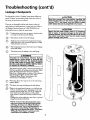
Troubleshooting (cont'd)
Leakage
Checkpoints
If you are not thoroughly familiar with electric codes, the
[
_kCAUTION
1
] Read this manual_efore
checkingthe
I
I water heater make sure the electric supply hasbeen I
]turned "OFF", and never turn the electric supplyJ
before the tank is completely full of water.
]
water heater, and safety practices, contact your local utility or
call Maytag Customer Service at 1-800-788-8899 for an
[
authorized servicerto check the water heater,
IiNever use this wat_ssA'
CAUTION
Use this guide to check a "Leaking" water heater. Many suspected "Leakers" are not leaking tanks. Often the source of
the water can be found and corrected.
L"°N"
1
it is completely _[
(_)
* Condensation may be seen on pipes in humid weather or pipe connections may be leaking.
| full of water. To prevent damage to the tank and I
/ heating element, the tank must be filled with water. I
/The water must flow from the hot water faucetl
@
* The primary anode rod may be leaking.
[ before turning "ON" power,
(_)
_
Small amounts of water from temperature-pressure
relief valve may. be due to thermal expansion or high
water pressure in your area.
* The temperature-pressure
at the tafik fitting.
relief valve may be leaking
The elements may be leaking
at
the tank fitting.
HAZARD OF ELECTRICAL SHOCK! Before
removing any access panels or servicing the
water heater, make sure the electrical supply
AWARNING
to the water heater
is turned "OFF". Failure to
do this could result in DEATH, SERIOUS BODILY INJURY, OR PROPERTY DAMAGE.
Turn electrica/power "OFF", remove access panels and
fold back insulation. If leaking around elements, follow
proper draining instructions and remove element.
t<.eposition or tel?lace gasket on element. Place element
into opening and tighten securely. Then follow
"Filling the Water Heater" instructions in the
"Instructions for Installation" section.
(_)
Water
drain valve may be due to the valve being
opened from
slightly.
(_)
*The drain valve may be leaking at the tank fitting.
r_-_c_
l
i
('-_
•Water in the water heater bottom or on the floor may
be from condensation, loose connections or the temperature-pressure refief valve. DO NOT replace the
water heater until a full inspection of all possible
water sources is made and necessary corrective steps
taken.
Leakage from other appliances, water lines, or ground
seepage should also be checked.
•NOTE: To check where threaded portion enters
tank, insert cotton swab between jacket opening
and fitting. If cotton is wet, follow"Drainlng"
instructions in the "Service and Maintenance" section and then remove fitting. Put pipe dope or
teflon tape on the threads and replace. Tlien follow
"Filling the Water Heater" instructions in the
_Instructions for Installation" section.
26
]
Repair Parts List
MAYTAG ELECTRICWATER HEATERS
MAYTAG/STATE
PART NUMBER CONVERSION KEY
MAYTAG
66001007
66001008
66001009
66001010
STATE
9002437
9002436
9002435
9002403
66001011
66001012
66001013
66001014
9001609
9001608
ETC2X
ETC5X
66001016
9002402
66001021
66001034
66001052
66001053
9001584
9002445
9002059
9000308
66001054
66001055
66001056
66001057
9000309
9001591
9002439
9002404
66001058
9002405
66001059
66001061
66001063
66001064
9002406
9002408
9002409
9002438
66001065
66001066
66001067
66001068
66001088
66001105
66001106
66001107
66001108
66001109
66001110
66001111
9002432
9002416
9002058
9001453
0002916160-2
9002769
9000225
9000396
9002988
9001830
9001792
9001672
27
Repair Parts List (cont'd)
MAYTAG ELECTRICWATER HEATERS
MODEL NUMBERS
HE21240S
HE31240S
HE21250S
HE31250S
40
40
50
50
GALLON
GALLON
GALLON
GALLON
NOTE:
UPPER ELEMENT:
These water
equipped with 3800 watt elements.
heaters
are
LOWER ELEMENT:
These water heaters are
equipped with factory installed convertible elements,
whic]i can be operated at 3800 watts or 5500 watts.
Convertible elements are not offered as replacement
parts.
r ..................................
L
If a replacement 3800 watt, 240 volt element is needed, order part no. 66001106 replacement element. If,
at the time of installation, the water heater was con66001107
replacement
plate "If Converted
box).element.
_--_
/
I
IF............
I
Ii
26
(See model rating
I
i t--,
......
]
i
I
li
I
Ii
_
]
25
4
verted to operate at 5500 watts, order part number
19
_
i
21
_
18
14-
28
_
2
[_
_3
I
Repair Parts List (cont'd)
MAYTAG ELECTRICWATER HEATERS
MODEL NUMBERS
HE212405
HE312405
HE212505
HE31250S
KEY
NO.
40
40
50
50
GALLON
GALLON
GALLON
GALLON
MODEL NUMBERS
HE312405
HE212505
NUMBERS
PART
DESCRIPTION
HE212405
1.
2.
3.
4.
5.
6.
7.
8.
9.
10.
Temperature-Pressure Relief Valve
Heat Trap Nipple
Pipe Insulation (2 each)
Dip Tube
Drain Valve
Drain Valve Washer (%f'x'3/_"x ¼"thick)*
Element Gasket
Lower Element
BussBar Kit
Thermostat Bracket
66001010
66001108
66001034
66001052
66001016
66001021
66001053
11.
12.
13.
66001007
66001056
--
--66001008
66001007
66001056
--
--66001008
14.
2 Pole Thermostat (Two Wire Lead Modeis)t
Terminal Cover (Lower)
Lower Thermostat w/Hi Limit
(Three Wire Lead Models)t
Terminal Cover (Lower Three Wire)
--
66001064
--
66001064
15.
16.
Adjustment Knob 1'/,"
Lower Access Panel
66001057
66001058
66001057
66001058
66001057
66001058
66001057
66001058
17.
18.
Upper Access Panel
Panel
66001059
66001060
66001059
66001060
66001059
66001060
66001059
66001060
19.
20.
21.
Terminal Cover (Upper)
UpperThermostatw/Hi
Limit
Thermostat Bracket
66001064
66001009
66001054
66001064
66001009
66001054
66001064
66001009
66001054
66001064
66001009
66001054
22.
23.
24.
Upper Element
Element Gasket
Drain Cover
66001053
66001063
SEE NOTE ON PAGE 28
66001053
66001053
66001063
66001063
66001053
66001063
25.
26.
#
Primary Anode
Secondary Anode/Heat Trap Nipple
Manual
66001055
66001054
66001109
66001110
66001010
66001010
66001108
66001108
66001034
66001034
66001052
66001065
66001016
66001016
66001021
66001021
66001053
66001053
SEE NOTE ON PAGE 28
66001055
66001055
66001054
66001054
66001109
66001109
66001110
66001110
66001088
HE312505
66001010
66001108
66001034
66001065
66001016
66001021
66001053
66001055
66001054
66001109
66001110
*Alsoavailableat mosthardwarestores.
_Referto WiringDiagramSectionforverification.
#Not Illustrated
Now that you have purchased this water heater, should a
need ever exist for repair parts or service, simply call Maytag
Customer Service at 1-800-788-8899 for an authorized ser-
The model number of the water heater will be found on the
model rating plate located above the access panel.
vicer. Be sure to provide all pertinent facts when you call or
visit.
WHEN ORDERING
THE FOLLOWING
Model Number
Serial Number
REPAIR PARTS, ALWAYS GIVE
INFORMATION:
Part Description
Part Number
THIS 1SA REPAIR PARTS LIST, NOTA
29
PACKING LIST.
Repair Parts List (cont'd)
MAY'rAG ELECTRICWATER HEATERS
MODEL NUMBERS
HE21250T
HE31250T
HE21282T
HE31282T
50
50
80
80
GALLON
GALLON
GALLON
GALLON
NOTE:
UPPER
ELEMENT:
These water
equipped with 3800 watt elements.
heaters
are
LOWER ELEMENT:
These water heaters are
equipped with factory installed convertible elements,
whi_l_ can be operated at 3800 watts or 5500 watts.
Convertible ele;nents are not offered as replacement
parts.
•..................................
If a replacement 3800 watt, 240 volt element is needed,
order part no. 66001106 replacement element. If, at
the time of installation, the water heater was converted
to operate at 5500 watts, order part number 66001107
..............
Converted" box).
- ........
repl-acement element
" (See m°del rating plate _If
_
12
!
1oIf'8
_I
. .
26_
14
!
_- 5
_
!
6_
?
3O
]
_
U
25
1
Repair Parts List (cont'd)
MAYTAG ELECTRICWATER HEATERS
MODEL NUMBERS
HE21250T
HE31250T
HE21282T
HE31282T
KEY
NO.
50
50
80
80
GALLON
GALLON
GALLON
GALLON
PART
DESCRIPTION
HE21250T
1.
2.
3.
4.
5.
6.
7.
8.
9.
10.
Temperature-Pressure Relief Valve
HeatTrapNipple
Pipe Insulation (2 each)
Dip Tube
Drain Valve
Drain Valve Washer ('½2"x 'Y_"x ¼"thick)*
Element Gasket
Lower Element
BussBar Kit
Thermostat Bracket
66001010
66001108
66001034
66001066
66001016
66001021
66001053
11.
12.
13.
MODEL NUMBERS
HE31250T
HE21282T
NUMBERS
HE31282T
66001010
66001108
66001034
66001067
66001016
66001021
66001053
66001055
66001054
66001010
66001010
66001108
66001108
66001034
66001034
66001066
66001067
66001016
66001016
66001021
66001021
66001053
66001053
SEE NOTE ON PAGE 30
66001055
66001055
66001054
66001054
66001007
66001056
--
--66001008
66001007
66001056
--
--66001008
14.
2 Pole Thermostat (Two Wire Lead Models)t
Terminal Cover (Lower)
Lower Thermostat w/Hi Limit
(Three Wire Lead Models)t
Terminal Cover (Lower Three Wire)
--
66001064
--
66001064
15.
16.
Adjustment Knob 1¼"
Lower AccessPanel
66001057
66001058
66001057
66001058
66001057
66001058
66001057
66001058
17.
18.
Upper AccessPanel
Panel
66001059
66001061
66001059
66001061
66001059
66001061
66001059
66001061
19.
20.
21.
Terminal Cover (Upper)
Upper Thermostat w/Hi Limit
Thermostat Bracket
66001056
66001009
66001054
66001056
66001009
66001054
66001056
66001009
66001054
66001056
66001009
66001054
22.
23.
24.
Upper Element
Element Gasket
Drain Cover
66001053
66001063
SEE NOTE ON PAGE 30
66001053
66001053
66001063
66001063
66001053
66001063
25.
26.
#
Primary Anode
Secondary Anode/Heat Trap Nipple
Manual
66001111
66001110
66001111
66001111
66001110
66001110
66001088
66001055
66001054
66001111
66001110
*Also available at most hardware stores.
tRefer to Wiring
#Not Illustrated
Diagram Section for verification.
Now that you have purchased this water heater, should a
need ever exist for repair parts or service, simply call Maytag
Customer Service at 1-800-788-8899 for an authorized ser-
The model number of the water heater will be found on the
model rating plate located above the access panel.
vicer. Be sure to provide all pertinent facts when you call or
visit.
WHEN ORDERING
THE FOLLOWING
Model Number
Serial Number
REPAIR PARTS, ALWAYS GIVE
INFORMATION:
Part Description
Part Number
THIS IS A REPAIR PARTS LIST, NOT A PACKING LIST.
31
Warranty
FULL ONE YEAR WARRANTY
For One Year from the date of Otiginal Retail Purchase, any part which fails in normal home use will be repaired or
replaced free of charge.
If a leak occurs in the Tank, a new water heater of the closest capacity and quality then available, will be replaced free
of charge.
The warranty of the replacement is the balance of the original water heater's Warranty.
LIMITED
PARTS WARRANTY
After the First year and through the Twelfth Year from the date of Original Retail Purchase, any Parts which fail due
to a defect in materials or workmanship, will be replaced or repaired free of charge for the part itself, with the owner
paying all other costs, including labor, mileage and transportation.
If the water heater is subjected to commercial, institutional, industrial or non-residential use, the above warranty coverage for parts that are proved to be defective in material or workmanship is effective for one year from the date of
the Original Retail Purchase.
The warranty of the replacement is the balance of the original water heater's Warranty, or twelve months from the
date of the part(s) purchase, whichever comes first.
The warranty is limited to the original owner of the water heater.
LIMITED
TANK WARRANTYAGAINST
LEAKS
After the First Year and through the Twelfth Year from the date of Original Retail Purchase, if a leak occurs in the
Tank, a new water heater of the closest capacity and quality then available, will be replaced free of charge for the
water heater, with the owner paying all other costs, including labor, mileage and transportation.
If the water heater is subjected to commercial, institutional, industrial or non-residential use, the above warranty coverage for tanks that are proven to be defective in material or workmanship is effective for two years from the date of
the Original Retail Purchase.
The warranty of the replacement is the balance of the original water heater's Warranty.
Please note: The Full and Limited Warranty appfies only while this water heater is used in the United States of America.
The warranty is limited to the original owner of the water heater.
TO RECEIVE WARRANTY
SERVICE
To locate an authorized service company in your area contact the Maytag dealer from whom your appfiance was purchased; or call Maytag Customer Service at the number fisted below. Should you not receive satisfactory warranty
service, please call or write:
Maytag Customer Service
p.o. Box 2370
Cleveland, TN 37320-2370
U.S.A. 1-800-788-8899
When contacting Maytag Customer Service be sure to provide the Modal and Serial Number of your appfiance, The
Name and Address of the Dealer from whom you purchased the appfiance and the Date of Purchase.
MAYTAG WATER HEATERS ARE MANUFACTURED
AND THIS WARRANTY PROVIDED BY
STATE INDUSTRIES, INC., ASHLAND CITY, TN. MAYTAG IS A TRADEMARK OF MAYTAG CORPORATION AND IS USED UNDER LICENSE TO STATE INDUSTRIES, INC.
09-01
66001088
0002916160-2