1
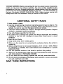
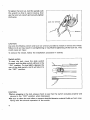
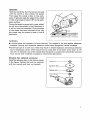
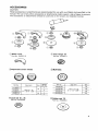
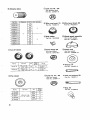
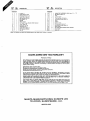
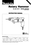
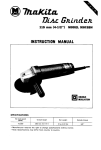
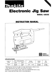
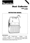
Angle Grinder
100 mm (4”) MODEL N900
INSTRUCTION MANUAL
No load speed
(RPM)
10,000
Overall length
1
255 mm (10”)
Net weight
1
1.5 kg (3.3lbs)
Spindle thread
1
Manufacturer reserves the right to change specifications without notice.
Note: Specifications may differ from country to country.
WARNING: For your personal safety, READ and UNDERSTAND before using.
SAVE THESE INSTRUCTIONS FOR FUTURE REFERENCE.
M l O x 1.25
IMPORTANT
SAFETY INSTRUCTIONS
(For All Tools)
WARNING: WHEN USING ELECTRIC TOOLS, BASIC SAFETY
PRECAUTIONS SHOULD ALWAYS BE FOLLOWED TO REDUCE
THE RISK OF FIRE, ELECTRIC SHOCK, AND PERSONAL
INJURY, INCLUDING THE FOLLOWING:
READ ALL INSTRUCTIONS.
1. KEEP WORK AREA CLEAN. Cluttered areas and benches invite injuries.
2. CONSIDER WORK AREA ENVIRONMENT. Don't use power tools in damp
or wet locations. Keep work area well lit. Don't expose power tools t o rain.
Don't use tool in presence of flammable liquids or gases.
3. KEEP CHILDREN AWAY. All visitors should be kept away from work area.
Don't let visitors contact tool or extension cord.
4. STORE IDLE TOOLS. When not in use, tools should be stored in dry, and high
or locked-up place - out of reach of children.
5. DON'T FORCE TOOL. It will do the job better and safer at the rate for which
it was intended.
6. USE RIGHT TOOL. Don't force small tool or attachment t o do the job of a
heavy-duty tool. Don't use tool for purpose not intended; for example, don't
use circular saw for cutting tree limbs or logs.
7. DRESS PROPERLY. Don't wear loose clothing or jewelry. They can be caught
in moving parts. Rubber gloves and non-skid footwear are recommended
when working outdoors. Wear protective hair covering t o contain long hair.
8. USE SAFETY GLASSES. Also use face or dust mask if cutting operation is
dusty.
9. DON'T ABUSE CORD. Never carry tool by cord or yank it t o disconnect from
receptacle. Keep cord from heat, oil, and sharp edges.
IO. SECURE WORK. Use clamps or a vise t o hold work. It's safer than using
your hand and it frees both hands t o operate tool.
11. DON'T OVERREACH. Keep proper footing and balance at all times.
12. MAINTAIN TOOLS WITH CARE. Keep tools sharp and clean for better and
safer performance. Follow instructions for lubricating and changing accessories. Inspect tool cords periodically and if damaged, have repaired by authorized service facility. Inspect extension cords periodically and replace if
damaged. Keep handles dry, clean, and free from oil and grease.
13. DISCONNECT TOOLS. When not in use, before servicing, and when changing accessories, such as blades, bits, cutters.
2
14. REMOVE ADJUSTING KEYS AND WRENCHES. Form habit of checking t o
see that keys and adjusting wrenches are removed from tool before turning
it on.
15. AVOID UNINTENTIONAL STARTING. Don't carry tool with finger on switch.
Be sure switch is OFF when plugging in.
16. EXTENSION CORDS. Make sure your extension cord is in good condition.
When using an extension cord, be sure to use one heavy enough t o carry
the current your product will draw. An undersized cord will cause a drop
in line voltage resulting in loss of power and overheating. Table 1 shows the
correct size to use depending on cord length and nameplate ampere rating.
If in doubt, use the next heavier gage. The smaller the gage number, the
heavier the cord.
TABLE 1
MINIMUM GAGE FOR CORD SETS
Total Length of Cord in Feet
0 - 25
26 - 50
Ampere Rating
More
Not More
Than
Than
0
6
-
10
-
12
-
-
100
101
-
150
AWG
6
10
18
12
16
16
14
~______
51
16
16
16
12
18
;:
1
14
12
14
12
Not Recommended
~
17. OUTDOOR USE EXTENSION CORDS. When tool is used outdoors, use only
extension cords intended for use outdoors and so marked.
18. STAY ALERT. Watch what you are doing, use common sense. Don't operate
tool when you are tired.
19. CHECK DAMAGED PARTS. Before further use of the tool, a guard or other
part that is damaged should be carefully checked to determine that it will
operate properly and perform its intended function. Check for alignment of
moving parts, binding of moving parts, breakage of parts, mounting, and any
other conditions that may affect its operation. A guard or other part that
is damaged should be properly repaired or replaced by an authorized service center unless otherwise indicated elsewhere in this instruction manual.
Have defective switches replaced by authorized service center. Don't use
tool if switch does not turn it on and off.
20. GUARD AGAINST ELECTRIC SHOCK. Prevent body contact with grounded
surfaces. For example; pipes, radiators, ranges, refrigerator enclosures.
21. REPLACEMENT PARTS. When servicing, use only identical replacement parts.
22. POLARIZED PLUGS. To reduce the risk of electric shock, this equipment has
a polarized plug (one blade is wider than the other). This plug will fit in a
polarized outlet only one way. If the plug does not fit fully in the outlet,
reverse the plug. If it still does not fit, contact a qualified electrician to install
the proper outlet. Do not change the plug in any way.
3
VOLTAGE WARNING: Before connecting the tool to a power source (receptacle,
outlet, etc.) be sure the voltage supplied is the same as that specified on the
nameplate of the tool. A power source with voltage greater than that specified
for the tool can result in SERIOUS INJURY to the user - as well as damage to
the tool. If in doubt, DO NOT PLUG IN THE TOOL. Using a power source with
voltage less than the nameplate rating is harmful to the motor.
ADDITIONAL SAFETY RULES
1. Keep guards in place.
2. Use only wheels having a maximum operating speed at least as high as "No
Load RPM" marked on the tool's nameplate. When using depressed center
wheels, be sure to use only fiberglass-reinforced wheels.
3.Check the wheel carefully for cracks or damage before operation. Replace
cracked or damaged wheel immediately.
4. Use only flanges specified for this tool.
5. Be careful not to damage the spindle, the flange (especially the installing
surface) or the lock nut. Damage to these parts could result in wheel
breakage.
6. Hold the tool firmly.
7. Keep hands away from rotating parts.
8. Make sure the wheel is not contacting the workpiece before the switch is
turned on.
9. Before using the tool on an actual workpiece, let it run for a while. Watch
for vibration or wobbling that could indicate poor installation or a poorly
balanced wheel.
IO. Use the specified surface of the wheel to perform the grinding.
11. Watch out for flying sparks. Hold the tool so that sparks fly away from you
and other persons or flammable materials.
12.Do not leave the tool running. Operate the tool only when hand-held.
13.Do not touch the workpiece immediately after operation; it may be extremely
hot and could burn your skin.
SAVE THESE INSTRUCTIONS.
4
Installing side grip (auxiliary handle)
Screw the same grip on the tool securely.
Installing or removing depressed center wheel
CAUTION:
Always be sure that the tool is switched off and unplugged before installing or removing
the wheel.
Screw the inner flange onto the spindle. Fit
the wheel on over the inner flange and screw
the lock nut onto the spindle.
Lock nut
Depressed
center wheel
CAUTION:
When installing the depressed center wheel,
screw the inner flange onto the spindle so
that the side with hub 16 mm (5/8") in outer diameter faces toward the depressed
center wheel.
When installing the diamond wheel or
abrasive disc, screw the inner flange onto the
spindle so that the side with hub 2 0 mm
(25/32") in outer diameter faces toward the
diamond wheel or abrasive disc.
5
To tighten the lock nut, hold the spindle with
the wrench so that it cannot revolve, then
use the lock nut wrench and securely tighten
clockwise.
Lock nut w e n c
If
\-wrench
CAUTION:
Use only the Makita wrench and lock nut wrench provided to install or remove the wheel.
Failure to do so may result in overtightening or insufficient tightening of the lock nut. This
could cause an injury.
To remove the wheel, follow the installation procedure in reverse.
Switch action
To start the tool, move the slide switch
forward, and the slide switch will lock in the
"ON" position. To stop lightly depress the
rear of the slide switch, and it will return t o
the "OFF" position.
Slide switch
I
0
I
CAUTION:
Before plugging in the tool, always check to see that the switch actuates properly and
returns to the "OFF" position when depressed.
Be sure to clean the tool often to prevent dust/dirt/abrasive material build-up from interfering with the smooth operation of the swtich.
6
Operation
Hold the tool firmly. Turn the tool on and wait
until the wheel or disc attains full speed.
Then apply the wheel or disc to the workpiece. In general, keep the edge of the wheel
or disc at an angle of about 15' to the workpiece surface.
During the break-in period with a new wheel,
do not work the grinder in the B direction or
it will cut into the workpiece. Once the edge
of the wheel has been rounded off by use,
the wheel may be worked in both A and B
directions.
I
I
-
WARNING:
It should never be necessary to force the tool. The weight of the tool applies adequate
pressure. Forcing and excessive pressure could cause dangerous wheel breakage.
Continued use of a worn-out wheel may result in wheel explosion and serious personal
injury. Depressed center wheel should not be used after it has been worn down t o 75
mm (3")in diameter. Use of the wheel after this point is unsafe and it should be removed
from service and rendered unusable by intentional destruction.
Abrasive disc (optional accessory)
Install the abrasive disc on the tool as shown
in the figure. Tighten the lock nut securely
with the wrench and lock nut wrench.
Lock nut
Abrasive disc
Rubber pad
1
Inner flange
----a
-&
7
MAINTENANCE
CAUTION:
Always be sure that the tool is switched off and unplugged before attempting to perform
inspection or maintenance.
To maintain product SAFETY and RELIABILITY, repairs, carbon brush inspection and replacement, any other maintenance or adjustment should be performed by Makita Authorized or
Factory Service Centers, always using Makita replacement parts.
8
ACCESSORIES
CAUTION:
These accessories or attachments are recommended for use with your Makita tool specified in this
manual. The use of any other accessories or attachments might present a risk of injury to persons.
The accessories or attachments should be used only in the proper and intended manner.
@Wheel cover
P a r t No. 344257-6
@Inner flange 35
P a r t No. 224291-1
@Depressed center wheels
@Multi-disc
Part No.
Size fmm)
1 0 0 x 4 ~1 6
Grit
Wheels
per pkg.
742038-00
@Lock nut 10-35
Part
No. 224545-6
I
100
@Rubber pad 76
P a r t No. 743009-6
9
@Lock nut 10 - 30
(For abrasive disc)
Part No. 224501-6
@Abrasive discs
742036-0-3
742037-8-3
742038-6-3
@Cut-off wheel
@ W i r e cup brush 75
Part No. 743201-4
@Wire bevel brush 85
Part No. 743203-0
@Grip holder
Part No. 164329-9
@Wheel guard assembly
(For cut-off wheel)
Part No. 122363-5
@Inner flange 30
(For flex wheel)
Part No. 224278-3
@Plastic pad
(For flex wheel)
Part No. 743009-1A
0
Wrench 14
Part No. 781007-2
@Lock nut 10 - 30
(For flex wheel)
Part No. 224541-4
@Flex wheel
Lock nut wrench 20
Part No. 782401-1
@ p Part No.
741404-OBP
Size lmm)
Wheels
per Pkg.
10
Grit
AC46
741404-OCP
10
741 404-ODP
ACE0
741404-OFP
AC120
I
10
10
Grip 36
Part No. 273506-3
100 mm (4")
ANGLE GRINDER
Model N900
Note: The switch and other part configurations
may differ from country to country.
11
MACHINE
~
1
2
3
4
5
6
7
8
9
10
11
12
13
14
15
1
1
1
1
1
1
1
1
2
1
1
1
1
1
1
0 Ring 11
Needle Bearing 810
Rstainmg Ring S- 12
Spiral Bevel Gear 36
Ball Bearing 6201LB
Flat Washer 12
Spindle
Wheel Cover
Pan Head Screw M5x20 IWith Washer)
Inner Flange 30
Lock Nut 10-30
Woodruff Key 3
Spiral Bevel Gear 11
Ball Bearing 6WOLB
Fan 52
16
17
18
19
20
21
22
24
25
26
27
28
29
E02
E03
1
1
1
2
1
1
1
1
1
1
1
1
6
1
1
ARMATURE ASSEMBLY lWlth Item 14 . 171
Ball Bearing 627LL8
Field
Carbon Brush
Terminal Base Complete
Housing Set IWith Item 271
Cord
Switch
Switch Lever
Compression Spring 6
Housing Set (With Item 211
Name Plate
Pan Head Screw M4x30 (With Washer)
Grip Holder
Grip 36
Note: The switch and other part specifications may differ from country t o country
MAKKA LIMITED ONE YEAR WARRANTY
Warranty Policy
Every Makrta tool is thoroughly inspected and tested before leaving the factory. It is warranted t o
be free of defects from w o r k m d p and materials for the period of ONE YEAR from the date of
on@
purchase. Should any trouble develop during this one-year period, return the COMPLETE
t w l , freight prepaid, to one of Makita’s Factory or Authorized Service Centers. If inspeetion shows
the trouble is caused by defective workmanship or material, Makita will repair (or at our option,
replaee) without charge.
This Wananty does not apply where:
repairs have been made or attempted by others:
repairs are required becauw of normal wear and tear:
The tool has been abused, misused or improperly maintained;
alterations have been made t o the tool.
IN NO EVENT SHALL MAKITA BE LIABLE FOR ANY INDIRECT, INCIDENTAL OR CONSEQUENTIAL DAMAGES FROM THE SALE OR USE O F THE PRODUCT. THIS DISCLAIMER
APPLIES BOTH DURING AND AFTER THE TERM O F THIS WARRANTY,
MAKITA DISCLAIMS LIABILITY FOR ANY IMPLIED WARRANTIES, INCLUDING IMPLIED
WARRANTIES O F “MERCHANTABILITY” AND “FITNESS FOR A SPECIFIC PURPOSE.”
AFTER THE ONE-YEAR TERM O F THIS WARRANTY.
This Wananty gives you specific legal rights, and you may also have other rights which vary from
state to state. Some s u t a d o not Puow the exclusion or limitation of incidental or c o n q u e n t i a l
damages, so the above limitation or excluaion m y not apply t o you. Some states d o not allow
limitation o n how long an implied WU~M(Yh t a , so the above limitation may not apply to you,
MAKITA MANUFACTURING EUROPE LTD
TELFORD, SHROPSHIRE, U.K.
883729-063