1
GMLN1040
EN
Hands-free Digital Car Kit
User Guide
GMLN1040
Hands-free Digital Car Kit
User Guide
INTRODUCTION
The Digital Car Kit provides additional operating convenience when
using the MTP700 TETRA radio in a vehicular environment. This User
Guide provides instructions for using the Digital Car Kit.
Before using the Digital Car Kit refer to the
Important Safety Instructions at the back of this user
guide. In addition read the Product Safety and RF
Exposure Booklet supplied with your portable
radio.
In addition to providing duplex hands-free communication, the Digital
Car Kit provides the following key features:
•
Whenever the radio is mounted in the cradle, the radio battery will
be charged automatically, within the temperature charging limits.
•
Phone and dispatch call types.
•
Entertainment mute, if enabled by your service provider, means
that the in-car Entertainment System will be muted if a call is
placed or received.
•
Auxiliary alert, if enabled by your service provider, allows external
indication of an incoming private call.
Note: The Auxiliary Alert feature must not be activated while
driving. If installed properly, the ignition signal will disable this
feature while the vehicle motor is running.
•
Data capabilities.
1
The Digital Car Kit with Digital Signal Processing (DSP), provides
enhanced audio quality even when driving at high speeds due to the
following features:
•
Full duplex operation permits two way audio to occur in Phone
mode. For more information refer to radio user manual.
•
Noise cancellation filters out ambient vehicle and road noise.
•
Echo cancellation minimises echo from your own voice in the system.
This Digital Car Kit is comprised of the following parts:
Radio cradle including battery charger, keys and interface cable
(GMLN1038). The Mounting Bracket is part of the cradle.
1.
RF Antenna Adapter with Mounting Tool (GMLX1037)
2.
Junction Box incl. mounting screws (GMLN1031).
3.
Power Cable (GMKN4135).
4.
Remote Directional Microphone (GMMN4065).
5.
Accessory Mounting Bracket (GMLN1039)
6.
Accessory Connector Kit (GMBN1021)
7.
Radio side connector Dust Cover (1586499Z01)
8.
Installation Manual (6866535D10).
9.
User Guide (6866535D09).
10. Passive Remote Speaker 5W (GMSN4078) or 10W (GMSN4066).
11. Remote PTT (RLN4857) or Footswitch with Remote PTT
(RLN4856) or Gooseneck with Remote PTT (RLN4858).
12. External antenna (FAE5521, FAE6003 or HAF4002).
Other available accessories are:
13. Handset (GMUN1006)
14. Fist Microphone (GMN4063)
15. TELCO Cable Extension (GMKN4106). This cable extension is
required to connect a Handset or a Fist Microphone.
16. Emergency Footswitch (RLN4836)
17. External Alarm Relay (GKN6272)
2
EUROPEAN UNION DIRECTIVE OF CONFORMANCE
STATEMENT
This product is in conformance with the requirements of the applicable
Council Directive 95/54/EC.
BATTERY VOLTAGE
The product is suitable for motor vehicles with a 12 volts electrical
system having negative earth only. For use in a 24 volts system an
approved separate 24V/12V DC/DC converter must be connected
between the vehicle battery and the digital car kit. For installation refer
to the separate installation instructions of the DC/DC converter. The
equipment must be installed according to the recommendations of the
Installation Manual and the vehicle manufacturer.
PREPARING THE PORTABLE RADIO FOR USING IN
THE VEHICLE ADAPTER
Before the radio can be used in the Vehicle Adapter it must be fitted with
an RF Switch adapter to allow for the automatic switching from integral
to external antenna. The RF Switch adapter fits between the portable
radio antenna socket and the portable radio antenna.
When the radio with the RF Switch adapter fitted is placed into the
Vehicle Adapter, the resulting combination operates as a mobile radio.
The following functions occur automatically:
•
The radio antenna is electrically disconnected and the vehicle
antenna is connected for use.
•
The radio internal microphone is electrically disconnected and the
Vehicle Adapter mobile microphone is connected for use.
•
The Vehicle Adapter charger is connected to the radio battery.
•
The Vehicle Adapter will automatically mute the radio internal
speaker and route received audio to the external speaker. The audio
level of the speaker is set by the radio volume control setting.
When using an external speaker, turn the volume
control up slowly to the desired audio level to avoid
damage from high audio pressures.
3
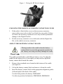
FITTING THE RF SWITCH ADAPTER
Never rotate the antenna or the black upper plastic
part of the adapter to fasten or unfasten the adapter
while in the radio's antenna socket. Doing so will
damage the adapter or the radio's antenna socket.
Always use the mounting tool supplied to rotate the
serrated metal wheel while holding the radio with
the other hand.
1.
Unscrew the radio antenna from the radio.
2.
Screw the antenna to the RF Switch Adapter. Hold the black upper
plastic part of the adapter with your fingers and rotate the antenna
until it sits fixed on the adapter.
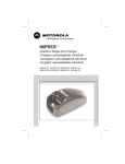
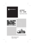
3.
Position the nose on the downside of the adapter so that it fits into
the slot of the radio's antenna socket (see figure 1).
4.
Hold the antenna or the black upper part of the adapter with your
fingers and turn the serrated metal wheel to screw the adapter into
the antenna socket. To fasten the adapter with the delivered
mounting tool, hold the radio with one hand, position the nose of
the mounting tool into one of the holes on the serrated metal wheel
and rotate the serrated metal wheel until it sits firmly on the radio's
antenna socket.
Note: With the RF Switch fitted there may be some degradation in radio
performance (up to 1.5dB). When the portable radio is operated in the
Vehicle Adapter, the vehicle antenna compensates for this degradation
and improves the overall radio performance.
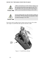
Figure 1. Fitting the RF Switch Adapter
4
Figure 1. Fitting the RF Switch Adapter
CHANGING THE RADIO'S ACCESSORY CONNECTOR COVER
1.
If the radio is fitted with a cover on the accessory connector,
remove this cover (refer to the User Guide for your radio). Failure
to remove the accessory connector cover may result in permanent
damage to the Digital Car Kit.
2.
Fit the accessory connector cover, delivered with the Digital Car
Kit, on the radio's accessory connector.
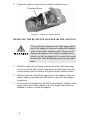
ADJUST THE BATTERY CONTACT BLOCK
Placing a radio in the cradle when the battery
contact block is not at the appropriate position for
the battery size being used may damage the cradle.
The cradle can hold radios with different battery sizes. To adapt the
cradle for the battery size of your radio you may need to adjust the
battery contact block inside the cradle.
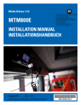
1.
Remove the crosshead screw located at the bottom of the cradle
(see figure 2).
2.
Lift up the battery contact block and remove it from the cradle.
3.
Insert the battery contact block in the appropriate alignment guides
(left and right) at the back of the cradle.
Use the front position for battery: PMNN4047
Use the rear position for batteries: PMNN4048, PMNN4049
5
4.
Fasten the battery contact block with the crosshead screw.
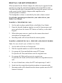
Crosshead Screw
Figure 2. Battery Contact Block
REMOVING THE RF SWITCH ADAPTER OR THE ANTENNA
Never rotate the antenna or the black upper plastic
part of the adapter to fasten or unfasten the adapter
while in the radio's antenna socket. Doing so will
damage the adapter or the radio's antenna socket.
Always use the mounting tool to rotate the serrated
metal wheel while holding the radio with the other
hand.
1.
Hold the radio with one hand, position the nose of the mounting
tool in one of the holes on the serrated metal wheel and rotate the
serrated metal wheel to loosen it from the radio's antenna socket.
2.
Hold the antenna or the black upper part of the adapter with your
fingers and turn the serrated metal wheel to unscrew the adapter
completely.
3.
To unscrew the antenna from the RF Switch Adapter, hold the black
upper plastic part of the adapter with your fingers and rotate the
antenna to remove it from the adapter.
6
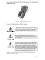
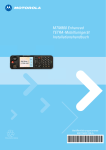
PLACING AND REMOVING THE RADIO TO AND FROM
THE CRADLE
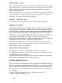
Figure 3. Digital Car Kit Cradle
PLACING THE RADIO IN THE CRADLE
DO NOT fit the battery alone into the cradle as it
will not be locked in place and may injure any
vehicle occupants in the event of a collision.
Remove locking key on the right side of the
VA cradle before driving, to avoid injury in case
of an accident.
To ensure correct fit of the radio into the cradle,
remove non-standard labels from the radio and
battery that are not shipped with the standard
product. Non-standard labels may be peeled off by
the action of installing the radio in the Cradle and
may also interfere with proper Digital Car Kit
operation or may damage the Digital Car Kit.
Note: For optimal operation, always turn the radio OFF before
inserting it into the cradle.
7
Make sure that the lock of the Vehicle Adapter is in
the open position before inserting or removing the
radio, otherwise the radio cannot be pushed back to
the correct position. The key should not be in the
lock while inserting or removing the radio to
prevent permanent damage to the cradle.
1.
Slide the radio with the battery attached into the cradle so that the
speaker grille faces outward and the controls are accessible.
2.
Push the radio backwards until it locks into place.
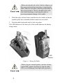
The LED indicator at the front side of the cradle indicates the battery
charge status.
LED
indicator
Figure 4. Fitting the Radio
When using an external speaker, turn the volume
control fully counter clockwise to turn the radio
OFF, to avoid damage from high audio pressures.
8
The radio can now be turned ON by slowly turning the volume control
knob clockwise until an acceptable volume level is reached. When the
radio detects the Vehicle Adapter, a signal is audible and the radio
display shows "Car Kit Connected". Once the radio is in the cradle and
is turned ON and has detected the Vehicle Adapter, it is automatically in
the Hands-free mode and ready for use.
WHEN MOUNTED IN THE VEHICLE ADAPTER THE
FOLLOWING OCCURS:
1.
The radio antenna is automatically disconnected and connection is
made from the radio via the Vehicle Adapter to the external vehicle
antenna.
2.
The radio's microphone and speaker are automatically disconnected
and connection is made to the externally connected microphone and
speaker (if hardware is connected and the radio recognized the
Vehicle Adapter).
3.
The radio battery is automatically connected to the battery charger
and charging commences.
The Vehicle Adaptor is permanently connected to
the vehicle battery. Be careful not to discharge the
vehicle battery by leaving the radio inserted or
allowing the radio to operate for extended periods of
time with the vehicle engine turned off.
Any radio and battery inserted in the Vehicle
Adapter is always actively connected to the
charging circuit regardless of whether the radio is
switched on or off.
9
REMOVING THE RADIO FROM THE CRADLE
Make sure that the lock of the Vehicle Adapter is in
the open position before removing the radio. The
key should not be in the lock while removing the
radio to prevent permanent damage to the cradle.
Do not pull the radio out of the Cradle by pulling on
the antenna. This may damage the antenna or cause
permanent damage to the radio.
Press down on the cradle release button on the left side of the cradle
(See Figure 5) and lift the radio upwards from the cradle.
Cradle
Release
Button
Figure 5. Cradle Release Button
10
DIGITAL CAR KIT OPERATION
When mounted in the Vehicle Adapter the radio may be operated in the
normal way using the external microphone and external PTT switch.
The radio internal audio is automatically disconnected and the received
audio routed via the Vehicle Adapter audio amplifier to the
external speaker or handset.
The loudspeaker volume is controlled by the radio volume control.
For all other operating procedures for your radio refer to your
Radio User Manual.
MAKING A TELEPHONE CALL
1.
Set the radio to phone mode (Refer to the Radio User Guide).
2.
Enter the desired telephone number or recall it from memory and
press and release the remote PTT button or Send key on the radio
keypad.
3.
When other party answers, speak into the remote directional
microphone to transmit audio.
4.
Incoming audio will be heard from the remote speaker.
MAKING A DISPATCH CALL - PRIVATE AND GROUP MODES
Note: For more details refer to Radio User Guide
1.
Set the radio to Private or Group mode.
2.
Dial the required number or recall it from the memory.
3.
For group call: Press and hold the remote PTT button.
For private call: Press and release wait for ring back tone.
4.
For group call: Wait until you receive a grant tone.
For private call: Audio will be heard, when receiving radio answers
call.
5.
In case of denial tone, release the PTT and repeat steps 3 and 4.
6.
Speak into the remote directional microphone to transmit audio.
7.
Incoming audio will be heard from the remote speaker once the PTT
button is released.
11
RECEIVING A CALL
When a private phone call is received, you will hear the ring tones via
the remote speaker. To answer the call press and release the remote PTT
button or Send key on the radio keypad and speak into the remote
directional microphone.
When a dispatch call is received, you will hear the callers voice from the
remote speaker. To answer the call, press the remote PTT button and
speak into the remote directional microphone.
ENDING A PHONE CALL
To end a phone call, press the End button on the radio keypad.
PERSONAL CALLS
Connecting a Handset to the Vehicle Adapter allows the user to make a
call in private. Picking up the Handset from its cradle causes the audio to
be routed from the remote speaker and remote directional microphone to
the speaker and the microphone of the Handset. The remote speaker is
muted. The user can enable and disable the remote speaker with the two
side buttons on the Handset. Placing a call or receiving a call is
performed as detailed above, with the exception that the PTT button on
the Handset is used in place of the remote PTT button.
Placing the Handset back into its cradle enables the remote speaker
again, however it does not end a phone call. To end a phone call, press
the End button on the radio keypad.
ADJUSTING THE VOLUME
Placing the radio into the cradle disables the radio´s internal
microphone and speaker and routes the audio to the remote directional
microphone and remote speaker.
Use the volume control knob located on top of the radio to control the
audio level of the Digital Car Kit remote speaker.
ENTERTAINMENT MUTE
If your in-vehicle entertainment system supports this capability and this
feature is connected at installation and enabled by your service provider,
the in-vehicle entertainment system will be muted if a call is placed or
received. To activate the Entertainment Mute feature, access the radio's
Car Kit Menu.
Press the ‘Menu’ Button then select ‘Battery/Accessory’ (9),
‘Car Kit’ (4) and ‘Ent Mute’ (1).
12
AUXILIARY ALERT
If this feature is connected at installation and enabled by your service
provider, it allows the user to be alerted to an incoming private call by
flashing the vehicle's headlights or sounding the horn. To activate the
Auxiliary Alert, access the radio's Car Kit Menu.
Press the ‘Menu’ Button then select Battery/Accessory’ (9),
‘Car Kit’ (4) and ‘Aux Alert’ (2).
Note: When the Vehicle Adapter is correctly installed the Auxiliary Alert
is disabled as long as the ignition switch is turned on.
13
CHARGING THE RADIO BATTERY
The Digital Car Kit is designed to operate with the appropriate TETRA
radio with Motorola-approved battery packs.
DO NOT fit the battery alone into the cradle as it
will not be locked in place and may injure any
vehicle occupants in the event of a collision.
When the radio is placed in the cradle, battery charging automatically
takes place regardless of whether the vehicle ignition is ON or OFF.
The charger will charge a completely discharged battery, to 90% of its
full capacity, within two hours when the radio is turned off. In case of a
completely flat radio battery, the Digital Car Kit will provide full
operation to the radio within two minutes of being placed in the cradle,
within the charging temperature limits.
Battery charging status can be determined by referring to the radio
display.
To ensure maximum battery life and accurate battery capacity
indication ensure, that before using a radio in the Digital Car Kit for the
first time, the battery has been fully charged in an IMPRES desktop
charger within the last month and that the battery is fully charged in an
IMPRES desktop charger at least once every month thereafter.
The ignition switch is bypassed and the Digital Car
Kit charges the radio battery from the vehicle
battery. Be careful not to discharge the vehicle
battery by leaving the radio inserted or allowing the
radio to operate for extended periods of time with
the vehicle engine turned off.
14
<=>$
?+@
Q?@
Y>
Q?[[[@
<>
Q##
Y=>$
Q\?][^#@
Q?#@
<_`{
Q|
Y_`{
Q#?}~+<@
Q#?[~<@
-
*
+
//
*+
!#$&*
+#;
!"#$%&
'*+
USING THE STANDARD DATA CABLE
Note: A data application program, installed on the computer is required
to be able to conduct a data session.
Connect the data cable (not supplied) from the data port on the Digital
Car Kit Junction Box to the serial communication port of the computer.
CLEANING OF CONNECTORS AND CONTACTS
Clean all connector pin and battery charge contact surfaces of the
Vehicle Adapter every three months, the RF contact surfaces of the
antenna adapter and the bottom connector contact surfaces of the
MTP700 Portable radio.
Note: Always use a fresh supply of alcohol and a clean container to
prevent contamination by dissolved material from previous use.
16
TROUBLESHOOTING
This section provides typical malfunctions that can occur during the
operation of the Digital Car Kit, and suggests corrective actions.
Prior to troubleshooting the malfunction, verify the following:
1.
Your radio functions properly outside the cradle.
2.
All cables to the junction box are connected and fastened properly.
Identify the malfunction in accordance to Table 2 below. If the
malfunction does not appear in Table 2, refer to your Service Provider.
Follow Table 2 steps after inserting the radio into the cradle .
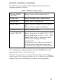
Table 2: Troubleshooting Procedures
No.
1
2
3
Malfunction
Radio inserted in
cradle does not
recognize car kit
Corrective Action
1.
Verify that the radio is properly inserted into
the cradle of the car kit.
2.
If malfunction persists, refer to your
service provider .
Display messsage
1.
‘Car Kit Connected’
is not displayed.
2.
Remove the radio from the cradle and install
it again.
Verify that the cradle connector is properly
connected to the junction box.
3.
If the malfunction persists, refer to your
Service Provider.
Charging Indication 1.
(LED) is not
illuminated, when a
2.
portable radio is in
the cradle.
3.
Remove the handset from the cradle and
install it again.
4.
Verify that the cradle connector is properly
connected to the junction box.
If the malfunction persists, refer to your
Service Provider.
Battery charging temperature below -30°C,
increase temperature.
17
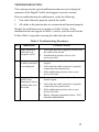
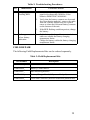
Table 2: Troubleshooting Procedures
No.
4
5
6
7
Malfunction
No sound is heard
from the remote
speaker.
Corrective Action
1.
Turn the radio on and set a medium volume.
When the radio detects the car kit, some ring
tones should be audible from the speaker.
2.
Verify that the remote speaker is properly
connected to the junction box.
3.
Remove the radio from the cradle and install
it again.
4.
If the malfunction persists, refer to your
Service Provider.
The other party in a 1.
phone call (Radio in
phone mode) does 2.
not hear your voice,
or, you do not get a 3.
response after a few
attempts.
A dispatch call
cannot be made.
Poor
communication.
18
Verify that the radio is ON and an active call
is present.
Verify that the remote directional
microphone is adjusted to your direction.
Verify that the remote directional
microphone is properly connected to the
junction box.
4.
Remove the radio from the cradle and install
it again.
5.
If the malfunction persists, refer to your
Service Provider.
1.
Verify that the remote PTT is properly
connected to the junction box.
2.
Verify that the cradle connector is properly
connected to the junction box.
3.
Remove the radio from the cradle and install
it again.
4.
If the malfunction persists, refer to your
Service Provider.
1.
Remove the radio from the cradle and install
it again.
2.
Verify that the car roof antenna is not
damaged or broken.
3.
Verify that the RF connector on the cradle is
not damaged or broken.
4.
Verify that the RF antenna adapter on the
radio is not damaged or broken.
5.
If the malfunction persists, refer to your
Service Provider.
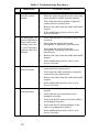
Table 2: Troubleshooting Procedures
No.
8
9
Malfunction
Corrective Action
Charging Indication 1.
Flashing RED.
Verify that the battery is one of the Motorola
approved rechargeable NiMH or LiIon
batteries PMNN 4047/4048/4049
2.
Verify that the battery contacts are clean and
free from foreign material - remove the radio
from the Vehicle Adapter and use a pencil
eraser to clean the four metal battery contacts
on the bottom of the unit.
3.
If the RED flashing condition persists, change
the battery.
Radio appears dead 1.
or low battery
indication.
Radio battery discharged due to extended
radio use outside the battery charging
temperature limits.
Charge the battery within the battery charging
temperature limits.
FIELD REPAIR
The following Field Replacements Kits can be ordered separately.
Table 3: Field Replacement Kits
Kit Number
Description
GMEN4095_
Radio Contact Block
GMEN4096_
Battery Contact Block
GMEN4097_
Ball Mounting Bracket
GMEN4098_
Battery Charger Board (fully assembled pcb)
GMEN4099_
Cable and Connector (between cradle and junction box)
19
IMPORTANT SAFETY INSTRUCTIONS
DO NOT fit the battery alone into the cradle as it will not
be locked in place and may injure any vehicle occupants in
the event of a collision.
1.To reduce risk of injury, use the Digital Car Kit only
with radios fitted with the authorized rechargeable
Motorola batteries. Other batteries may explode,
causing personal injury and damage.
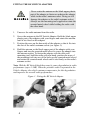
2. Do not place your Digital Car Kit and/or portable
radio in the area over an air bag or in the air bag
deployment area. Air bags inflate with great force. If a
portable radio is placed in the air bag deployment area
and the air bag inflates, the radio may be propelled
with great force and cause serious injury to occupants
of the vehicle.
3. Do not install or remove your radio in a potentially
explosive atmosphere. It is rare, but contact sparking
may occur while installing or removing the radio.
Sparks in such areas could cause an explosion or fire,
resulting in bodily injury or even death.
Note: Areas with potentially explosive atmospheres
include fuelling areas, areas where the air contains
chemicals or particles such as grain dust or metal
powders and any area where you would normally be
advised to turn off a vehicle engine. Areas with
potentially explosive atmosphere are often, but not
always, posted.
4. Do not transport or store flammable gas, flammable
liquids or explosives in the compartment of your
vehicle that contains your Digital Car Kit or
accessories.
5. To avoid possible interference with blasting
operations, turn your radio off before entering an area
where you may be close to electrical blasting caps, in
a "blasting area" or in areas posted "Turn off two-way
radios". Obey all signs and instructions.
20
OPERATIONAL CAUTIONS
1. Most modern electronic equipment, typically
equipment in ambulances and navigation equipment
are shielded from RF energy. RF energy from your
radio may however interfere with some equipment.
Consult your physician, or the manufacturer of any
personal medical devices (such as pacemakers, hearing aids etc.) to determine if they are shielded from
external RF energy.
2. Turn your radio OFF in any health care facilities
when any regulations posted in these areas instruct
you to do so. Always request permission before using
your radio or Digital Car Kit near to medical equipment.
OPERATIONAL SAFETY GUIDELINES
1.
This equipment is not suitable for outdoor use. Use only in dry
locations. Ensure that rain or snow cannot reach the Digital Car Kit
through an open vehicle window.
2.
Replacement fuses fitted in the Digital Car Kit installation must
comply with the type and rating specified in the equipment
instructions.
3.
Maximum ambient temperature around the Digital Car Kit must not
exceed 60°C (140°F).
4.
Prevent foreign objects or fluids from falling into the Digital Car
Kit.
21
COMPLIANCE WITH RF ENERGY EXPOSURE STANDARDS
Your Motorola radio is designed and tested to comply with a number of
national and international standards and guidelines regarding human
exposure to radio frequency electromagnetic energy including:
•
Institute of Electrical and Electronic Engineers (IEEE) C95.1-1999
Edition
•
International Commission on Non-Ionizing Radiation Protection
(ICNIRP) 1998
•
United States Federal Communications Commission, Code of Federal Regulations; 47 CFR part 2 sub-part J
•
American National Standards Institute (ANSI) / Institute of Electrical and Electronic Engineers (IEEE) C95. 1-1992
•
Ministry of Health (Canada) Safety Code 6. Limits of Human Exposure to Radiofrequency Electromagnetic Fields in the Frequency
Range from 3 kHz to 300 GHz, 1999
•
Australian Communications Authority Radiocommunications
(Electromagnetic Radiation - Human Exposure) Standard 2001
•
ANATEL, Brasil Regulatory Authority, Resolution 256 (April 11,
2001) "additional requirements for SMR, cellular and PCS product
certification."
22
OPERATIONAL INSTRUCTIONS
Transmit and Receive
•
To transmit (talk), push the remote Push-To-Talk (PTT) button; to
receive, release the remote PTT button.
•
Transmit only when people outside the vehicle are at least the
minimum lateral distance away , as shown in Table 3, from a
properly installed, externally-mounted antenna.
Note: Table 1 lists the minimum lateral distance for bystanders in an
uncontrolled environment from the transmitting types of antennas,
(i.e. monopoles over a ground plane, or dipoles) at several different
ranges of rated radio power for mobile radios installed in a vehicle.
Table 4: Rated Power and Lateral Distance
Rated Power of Radio
(and external Antenna)
Minimum lateral distance from
Transmitting Antenna
Less than 7 watts
20 cm (8 inches)
7 to 15 watts
30 cm (1 foot)
23
24
© 2003 by Motorola, Inc.
, Motorola are trademarks of Motorola, Inc.
All other trademarks mentioned in this user guide are trademarks of their respective
companies.
All Rights Reserved
6866535D09
@6866535D09@