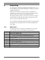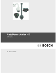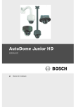
1
IP-54 In-ceiling Mount
VJR-A3-IC54
en
Mounting Guide
AutoDome Junior
Table of Contents | en
3
Table of Contents
1
Important Safety Instructions
4
2
Unpacking
6
2.1
Parts List
6
3
Installing a Recessed Mount
7
3.1
Description
7
3.1.1
Additional Requirements
9
3.1.2
Preparing the Ceiling for Installation
9
3.1.3
Installing the Camera to the Mounting Plate
Bosch Security Systems, Inc.
Mounting Guide
15
F.01U.201.538 | 1.0 | 2010.12
4
1
en | Important Safety Instructions
AutoDome Junior
Important Safety Instructions
Read, follow, and retain all of the following safety instructions.
Heed all warnings on the unit and in the operating instructions
before operation.
1.
Clean only with a dry cloth. Do not use liquid cleaners or
aerosol cleaners.
2.
Do not install unit near any heat sources such as radiators,
heaters, stoves, or other equipment (including amplifiers)
that produce heat.
3.
Do not block any ventilation openings.
4.
Do not use the unit near water or expose to rain or
5.
Unplug the unit during lightning storms or when unused for
moisture. Never spill liquid of any kind on the unit.
long periods.
6.
Adjust only those controls specified in the operating
instructions.
7.
Do not overload outlets and extension cords, as this can
8.
Protect the plug and power cord from foot traffic or
9.
Operate the unit only from the type of power source
cause fire or electrical shock.
pinching, at electrical outlets, and at its exit from the unit.
indicated on the label.
10. Unless qualified, do not attempt to service a damaged unit
yourself. Refer all servicing to qualified service personnel.
11. Use only replacement parts specified by the manufacturer.
12. Install in accordance with the manufacturer's instructions
in accordance with applicable local codes. Use only
attachments/accessories specified by the manufacturer.
Equipment change or modification could void the user's
guarantee or authorization agreement.
F.01U.201.538 | 1.0 | 2010.12
Mounting Guide
Bosch Security Systems, Inc.
AutoDome Junior
Important Safety Instructions | en
5
DANGER!
High risk: This symbol indicates an imminently hazardous
situation such as “Dangerous Voltage” inside the product.
If not avoided, this will result in an electrical shock, serious
bodily injury, or death.
WARNING!
Medium risk: Indicates a potentially hazardous situation.
If not avoided, this could result in minor or moderate bodily
injury.
CAUTION!
Low risk: Indicates a potentially hazardous situation.
if not avoided, this could result in property damage or risk of
damage to the unit.
You can view and print the full version of this Installation
Manual with Adobe Acrobat Reader, both provided on the
enclosed CD-ROM. This user guide is the intellectual property
of Bosch Security Systems; protected by copyright. Contact:
www.BoschSecurity.com
Bosch Security Systems, Inc.
Mounting Guide
F.01U.201.538 | 1.0 | 2010.12
6
en | Unpacking
2
AutoDome Junior
Unpacking
This equipment should be unpacked and handled with care. If
an item appears to have been damaged in shipment, notify the
shipper immediately.
Verify that all the parts listed in the Parts List below are
included. If any items are missing, notify your Bosch Security
Systems Sales or Customer Service Representative.
The original packing carton is the safest container in which to
transport the unit and must be used if returning the unit for
service. Save it for possible future use.
This installation should be made by qualified service personnel
and conform to the National Electrical Code and applicable
local codes.
2.1
Parts List
The following table lists the parts included with the VJR-A3IC54 AutoDome Junior IP54-rated In-ceiling mount kit:
Quantity
3
1
Part
VJR-A3-JW Junction Box
–
M4–.7 x 8 Phillips Pan Head Machine Screws
–
#10–32 x 3/8 Phillips Pan Head Machine Screw
1
4
4
4
1
1
1
VJR-A3-IC54BK
–
IP54-rated Mounting Bracket with Clamp Plate
–
M4 x 16 Phillips Pan Head Machine Screws
–
M3 x 10 Torx Screws
–
O-rings, 3.97 mm I.D. by Ø1.78 mm
–
White trim ring with 2 (two) M3 captive screws
–
Black trim ring with 2 (two) M3 captive screws
–
Mounting Guide
F.01U.201.538 | 1.0 | 2010.12
Mounting Guide
Bosch Security Systems, Inc.
AutoDome Junior
Installing a Recessed Mount | en
3
Installing a Recessed Mount
3.1
Description
7
This chapter details how to recess mount the AutoDome Junior.
NOTICE!
The image sensors in modern cameras are highly sensitive and
require special care for proper performance and extended
lifetime. Follow the guidelines for optimum results with your
camera:
–
Do not expose to direct sunlight or bright spotlights in
operating and nonoperating conditions.
–
Avoid bright lights in the field of view of the camera. Bright
lights cause a “smearing” effect, which is visible as white
lines above and below the highlight. Prolonged exposure to
bright lights may cause bleaching of the sensor's color
filters. This will be visible as colored spots in the picture
and is irreversible.
Bosch Security Systems, Inc.
Mounting Guide
F.01U.201.538 | 1.0 | 2010.12
8
en | Installing a Recessed Mount
AutoDome Junior
Mounting Assembly
The following illustrations shows the components of the recess
mount:
Figure 3.1
1
2
3
4
AutoDome Junior with IP54-rated In-ceiling Mount
VJR-A3-JW Junction Box
Mounting Bracket
AutoDome Junior Camera
Trim Skirt
F.01U.201.538 | 1.0 | 2010.12
Mounting Guide
Bosch Security Systems, Inc.
AutoDome Junior
3.1.1
Installing a Recessed Mount | en
9
Additional Requirements
–
Appropriate straight slot screwdrivers
–
No. 2 Phillips screwdriver
–
Appropriate tool for cutting a hole in drywall or ceiling tile
(if applicable)
–
T-10 Torx wrench
–
Retaining ring with gasket
(supplied with AutoDome Junior camera kit)
–
Three (3) M3 – .5 x 6 Phillips flat head machine screws for
use with the retaining ring
(supplied with AutoDome Junior camera kit)
–
VJR-A3-SP, support kit for VJR-A3-IC54 mounting kit, if
mounting to a drop ceiling
3.1.2
Preparing the Ceiling for Installation
To mount to a recess mount, do the following:
1.
Determine a secure location for the recessed mount.
145
(5.7)
70
(2.8)
mm
(in.)
229
(9.0)
Figure 3.2 Recess Mount Dimensions
Bosch Security Systems, Inc.
Mounting Guide
F.01U.201.538 | 1.0 | 2010.12
10
en | Installing a Recessed Mount
2.
AutoDome Junior
Drill or cut a 200 mm hole with a tolerance of 2.2 mm ( 7.9
in. ± 1/8).
3.
Optional: if installing the AutoDome Junior to a suspended
ceiling tile or any other surface where additional support is
required, the VJR-A3-SP mounting kit is recommended
(supplied separately).
4.
Ensure that the gasket is attached to the retaining ring. If
the gasket and the retaining ring are separate:
a.
Locate the flat side of the gasket and the recessed
side of the retaining ring.
b.
Thread the flat side of the gasket (item 1, below) onto
the recessed side of the retaining ring (item 2). The
illustration below shows a cross-section of the gasket
on the retaining ring.
CAUTION!
You must ensure that the gasket is attached to the retaining
ring as shown above to ensure an environmentally tight seal.
F.01U.201.538 | 1.0 | 2010.12
Mounting Guide
Bosch Security Systems, Inc.
AutoDome Junior
5.
Installing a Recessed Mount | en
11
Attach the retaining ring with gasket (item 2, below) to the
VJR-A3-JW. These parts are supplied with the AutoDome
Junior Camera. Ensure that the side of the retaining ring
with the counter-sunk screw holes is facing you.
Figure 3.3 O-ring and retaining ring placement for outdoor installation
1
M3 – .5 x 6 Phillips flat head machine screws
2
(supplied with AutoDome Junior Camera)
Retaining ring with gasket
(supplied with AutoDome Junior Camera)
6.
Determine the side of the VJR-A3-JW in which the external
wires are to be routed and remove the plug from the
knockout.
7.
Apply a 1/2-in. (15-mm) NPS fitting to the chosen
knockout. Ensure a water-tight fitting to maintain the IP
Environmental Protection Rating for the unit.
8.
Align the holes of the VJR-A3-JW with the mounting
bracket. Ensure that the VJR-A3-JW knockouts are not
covered by the bracket arms.
9.
Thread the four (4) 3.97 mm I.D. by Ø1.78 mm O-rings
(item 1, Figure 3.4) onto the four (4) M4 x 16 Phillips Pan
Head Machine Screws.
Bosch Security Systems, Inc.
Mounting Guide
F.01U.201.538 | 1.0 | 2010.12
12
en | Installing a Recessed Mount
AutoDome Junior
10. Attach the VJR-A3-JW to the mounting bracket using the
four (4) M4 x 16 Phillips Pan Head Machine Screws (item
2, below).
Figure 3.4
Attach VJR-A3-JW to Mounting Bracket
11. Align the holes of mounting plate with the VJR-A3-JW
junction box and attach with the three (3) M4–.7 x 8
Phillips Pan Head Machine Screws.
F.01U.201.538 | 1.0 | 2010.12
Mounting Guide
Bosch Security Systems, Inc.
AutoDome Junior
Installing a Recessed Mount | en
13
Figure 3.5 Attach Mounting Plate to VJR-A3-JW
12. Loosen the two clamp drive screws (item 1, below) so that
the clamping plates (item 2) move freely.
Figure 3.6 Clamp Drive Screws and Plates
13. Insert the bracket through the hole in the ceiling. Slide
clamps out and down so that the ceiling/drywall is
captured in between the clamps and the bracket flange.
The ceiling/drywall must have a maximum thickness of
41.7 mm (1.64 in.) and a minimum thickness of 12.7 mm
(0.50 in.).
Bosch Security Systems, Inc.
Mounting Guide
F.01U.201.538 | 1.0 | 2010.12
14
en | Installing a Recessed Mount
Figure 3.7
AutoDome Junior
Attach Recess Mount to Ceiling
14. Tighten both clamps using the clamp drive screws
(installed on the assembly) and a #2 Phillips screwdriver.
Figure 3.8
Tighten Mounting Clamps
NOTICE!
Over-torquing the ceiling clamps can damage the clamp or
ceiling. Only tighten the clamp until it contacts the ceiling and
you start to feel some resistance. If using a power screwdriver,
set the torque level to the lowest setting.
F.01U.201.538 | 1.0 | 2010.12
Mounting Guide
Bosch Security Systems, Inc.
AutoDome Junior
Installing a Recessed Mount | en
15
NOTICE!
If you need to install the VJR-A3-SP Support Bracket, refer to
the guide included with the bracket. Once the bracket is
installed, continue with the next section.
3.1.3
Installing the Camera to the Mounting Plate
To install the base to a surface or suspended ceiling using the
supplied mounting plate, do the following:
1.
Loosen the single safety locking screw on the base of the
unit using the user-supplied T-10 Torx wrench.
Figure 3.9 Unlock Safety Locking Screw
CAUTION!
All wires for installation applications must be routed through a
grounded conduit.
2.
Remove the screw from the Earth ground (
)on the
inside of the VJR-A3-JW.
3.
Attach a user-supplied ground wire to the Earth ground
(
) screw hole on the VJR-A3-JW and secure with the
screw.
4.
Attach the green grounding wire from the unit to the
grounded (
) screw hole on the VJR-A3-JW using the
attached captive screw washer.
5.
Route wires through the knockout on the VJR-A3-JW.
Bosch Security Systems, Inc.
Mounting Guide
F.01U.201.538 | 1.0 | 2010.12
16
en | Installing a Recessed Mount
6.
AutoDome Junior
Connect the mating connectors (supplied in the VJR
AutoDome accessory kit) with the flying leads to the user
supplied wiring (see the AutoDome Junior Installation
Manual for complete wiring information).
7.
Plug the matching connectors from the camera into the
8.
Attach the camera to the mounting plate by inserting the
mating connectors from the ceiling.
vertical tab on the plate (item 1, below) into the recessed
slot on the top of the camera dome (Item 3) to the right of
the safety locking screw (item 2).
Note: Do not loosen the three brass buttons. These brass
buttons engage the slotted tabs on the mounting plate.
Figure 3.10
1
2
3
Tab/Slot Alignment Detail
Vertical Tab (on mounting plate)
Locking Screw
Recessed Slot (on dome housing)
F.01U.201.538 | 1.0 | 2010.12
Mounting Guide
Bosch Security Systems, Inc.
AutoDome Junior
9.
Installing a Recessed Mount | en
17
Rotate the camera approximately 15 degrees in the
clockwise direction. Then, lock firmly into place, as shown
in the next illustration.
Figure 3.11
10.
Attach Dome to Mounting Plate
Ensure unit is centered.
NOTICE!
The recessed mounting bracket is provided with an additional
safety tether point (item 1, Figure 3.11). To prevent injury,
attach a safety wire from a secure anchor point above the
ceiling to this tether point.
Bosch Security Systems, Inc.
Mounting Guide
F.01U.201.538 | 1.0 | 2010.12
18
en | Installing a Recessed Mount
AutoDome Junior
11. Align trim ring so the four alignment posts (item 1, below)
align with the recesses in the camera housing (item 2) and
so the two safety screws align with the off center holes
(item 3) on the locking clamps.
Note: The two (2) sets of raised stand-off tabs (item 4) on
each side of the trim ring align with the locking clamps.
Figure 3.12
1
2
3
4
Align Trim Ring
Alignment Tabs (four)
Align tabs to the recessed areas on the housing
Align safety locking screws to these connections
Stand-off Tabs (two)
12. Snap trim ring into place. Ensure snaps are secure by
attempting to lightly turn unit. Note: Unit should not turn.
13. Use the supplied T-10 Torx wrench to secure the trim
ring’s two (2) safety locking screws to the mounting
bracket.
F.01U.201.538 | 1.0 | 2010.12
Mounting Guide
Bosch Security Systems, Inc.
Bosch Security Systems, Inc.
850 Greenfield Road
Lancaster, PA 17601
U.S.A.
www.boschsecurity.com
© Bosch Security Systems, Inc., 2010