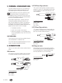
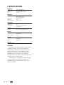
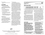
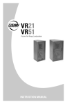
1
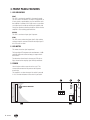
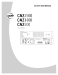
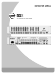
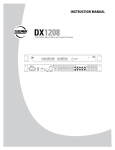
INSTRUCTION MANUAL
CXA240
Power Amplifier
DC
CXA240 - AMPLIFIER
24V
OUTPUT
DC POWER
115VAC/230VAC~ 60Hz/50Hz
115
ON
OFF
COM
CAUTION
RISK OF ELECTRIC SHOCK
DO NOT OPEN
100V
PUSH
WARNING
TO REDUCE THE RISK
OF FIRE OR ELECTRIC
SHOCK, DO NOT EXPOSE
THIS APPARATUS TO
RAIN OR MOISTURE.
RISK OF HAZARDOUS
ENERGY! MAKE PROPER
SPEAKER CONNECTION.
SEE INSTRUCTIONS
BEFORE USING!
F
E
US
FUSE
PUSH
E
FUSE
70V
IV/10K BAL.
LEVEL
ADJUST
FUS
115VAC/230VAC~ 60Hz/50Hz
COM
LINE
DC FUSE
6.3AL 250V
4
INPUT
CAUTION : SHOCK HAZARD-DO NOT OPEN
RISK OF FIRE-REPLACE FUSE AS MARKED.
GND
MANUFACTURED IN CHINA © 2004 LOUD TECHNOLOGIES INC.
"EAW" IS A REGISTERED TRADEMARK OF LOUD TECHNOLOGIES INC.
OUTPUT
CXA240 - AMPLIFIER
PROT
SIGNAL
PEAK
POWER
CAUTION
AVIS
RISK OF ELECTRIC SHOCK • DO NOT OPEN
RISQUE DE CHOC ELECTRIQUE
NE PAS OUVRIR
CAUTION: TO REDUCE THE RISK OF ELECTRIC SHOCK
DO NOT REMOVE COVER (OR BACK)
NO USER-SERVICEABLE PARTS INSIDE
REFER SERVICING TO QUALIFIED PERSONNEL
ATTENTION: POUR EVITER LES RISQUES DE CHOC
ELECTRIQUE, NE PAS ENLEVER LE COUVERCLE. AUCUN
ENTRETIEN DE PIECES INTERIEURES PAR L'USAGER. CONFIER
L'ENTRETIEN AU PERSONNEL QUALIFIE.
AVIS: POUR EVITER LES RISQUES D'INCENDIE OU
D'ELECTROCUTION, N'EXPOSEZ PAS CET ARTICLE
A LA PLUIE OU A L'HUMIDITE
The lightning flash with arrowhead symbol within an equilateral triangle is
intended to alert the user to the presence of uninsulated "dangerous voltage"
within the product's enclosure, that may be of sufficient magnitude to constitute
a risk of electric shock to persons.
Le symbole éclair avec point de flèche à l'intérieur d'un triangle équilatéral est
utilisé pour alerter l'utilisateur de la présence à l'intérieur du coffret de "voltage
dangereux" non isolé d'ampleur suffisante pour constituer un risque d'éléctrocution.
The exclamation point within an equilateral triangle is intended to alert the user
of the presence of important operating and maintenance (servicing) instructions
in the literature accompanying the appliance.
Le point d'exclamation à l'intérieur d'un triangle équilatéral est employé pour
alerter les utilisateurs de la présence d'instructions importantes pour le fonctionnement et l'entretien (service) dans le livret d'instruction accompagnant l'appareil.
1. SAFETY INSTRUCTIONS
1.
2.
3.
4.
5.
6.
7.
8.
9.
10.
11.
12.
Read these instructions.
Keep these instructions.
Heed all warnings.
Follow all instructions.
Do not use this apparatus near water.
Clean only with dry cloth.
Do not block any ventilation openings. Install in
accordance with the manufacturer’s instructions.
Do not install near any heat sources such as radiators,
heat registers, stoves, or other apparatus (including
amplifiers) that produce heat.
Do not defeat the safety purpose of the polarized or
grounding-type plug. A polarized plug has two blades with
one wider than the other. A grounding type plug has two
blades and a third grounding prong. The wide blade or the
third prong are provided for your safety. If the provided
plug does not fit into your outlet, consult an electrician for
replacement of the obsolete outlet.
Protect the power cord from being walked on or pinched
particularly at plugs, convenience receptacles, and the
point where they exit from the apparatus.
Only use attachments/accessories specified by the
manufacturer.
Use only with the cart, stand, tripod,
bracket, or table specified by the
manufacturer, or sold with the
apparatus. When a cart is used, use
caution when moving the cart/
apparatus combination to avoid injury
from tip-over.
13. Unplug this apparatus during lightning storms or when
unused for long periods of time.
14. Refer all servicing to qualified service personnel. Servicing
is required when the apparatus has been damaged in any
way, such as power-supply cord or plug is damaged, liquid
has been spilled or objects have fallen into the apparatus,
the apparatus has been exposed to rain or moisture, does
not operate normally, or has been dropped.
15. This apparatus must be connected to a mains socket outlet
with a protective earthing connection (the third grounding
prong).
16. This apparatus has been equipped with an all-pole, rockerstyle AC mains power switch. This switch is located on the
front panel and should remain readily accessible to the user.
WARNING: To reduce the risk of fire or electric shock, do
not expose this apparatus to rain or moisture.
WARNING: The 70 V and 100 V output terminals are
potentially HAZARDOUS and any external wiring connected
to these terminals requires installation by an INSTRUCTED
PERSON or the use of ready-made leads or cords.
WARNING: This equipment has been designed to be
installed by qualified professionals only! There are many
factors to be considered when installing professional
sound reinforcement systems, including mechanical and
electrical considerations, as well as acoustic coverage and
performance. EAW Commercial strongly recommends that
this equipment be installed only by a professional sound
installer or contractor.
TABLE OF CONTENTS
1. SAFETY INSTRUCTIONS ...................................................2
2. INTRODUCTION..................................................................3
KEY FEATURES............................................................3
APPLICATIONS ...........................................................3
3. FRONT PANEL FEATURES .................................................4
4. REAR PANEL FEATURES....................................................5
5. THERMAL CONSIDERATIONS ..........................................8
6. CONNECTIONS ...................................................................8
7. TYPICAL HOOKUP DIAGRAM...........................................9
8. SPECIFICATIONS..............................................................10
BLOCK DIAGRAM .....................................................11
9. SERVICE INFORMATION .................................................11
10. EAW COMMERCIAL WARRANTY ................................11
Part No. 0010172 Rev. A 05/04
© 2004 LOUD Technologies Inc. All Rights Reserved. Printed in China.
2 – CXA240
2. INTRODUCTION
The CXA240 is designed for continuous duty in speech,
music, paging and sound reinforcement applications in
churches, schools, offices, arenas, hotel meeting rooms,
convention centers, recreation facilities and other venues
demanding high performance, flexible features, and rugged
dependability.
The CXA240 has a 240 watt power amplifier, with an
internal output transformer. The outputs are screw terminals
that accept bare wire or spade terminals.
There are four inputs: two unbalanced RCA, and two
combination inputs, capable of accepting balanced XLR,
1/4" TRS, or unbalanced 1/4" TS connections from line-level
sources. A rear panel level control allows adjustment of the
input signals.
Output modes include 4Ω low impedance, and 70 V
and 100 V constant voltage. The smart output stage is fully
protected against permanent damage caused by overloading,
shorts, and extreme temperatures.
The CXA240 operates on either 115 or 230 VAC, 50/60Hz,
determined by a rear panel voltage select switch, and is
supplied by a detachable IEC power cord.
A rear panel terminal strip connection is provided for
connecting an external 24 VDC backup battery, with a rear
panel DC power switch.
KEY FEATURES
• Two balanced/unbalanced XLR/TRS combination inputs
• Two RCA unbalanced inputs
• Adjustable rear panel level control
• 240 watt rms power output
• Fan cooled
• 4-ohm low-impedance screw-terminal outputs
• 70 V and 100 V constant voltage screw-terminal
outputs
• Discrete component high-power amplifier
• Switchable 24 VDC Backup Power Input
• 3 RU Rack-Mounting
• Front panel handles
APPLICATIONS
• Foreground/Background Music Systems
• Sound Reinforcement Systems
• Paging Systems
• Continuous-Duty Applications
The front panel provides a meter that indicates output
signal strength, ranging from –20 dB to 0 dB and clipping.
Three status LEDs on the front panel show when the
amplifier has a signal present, when the amplifier is in
protection mode, and when the peak output is reached.
The front panel incorporates holes for rack mounting, and it
will take up three rack spaces. There are two handles fitted on
the front panel.
CXA240 – 3
3. FRONT PANEL FEATURES
1. LED INDICATORS
PROT
This LED is on when the amplifier is in protection mode.
This can occur if the volume is too high for long periods, or
if heavy loads, a speaker defect, or poor ventilation cause
the amplifier to overheat. If this light comes on, turn down
your input signal to avoid over-working the amplifier, and
check your speakers and wiring for defects. Check that the
amplifier is also receiving good ventilation.
SIGNAL
This LED is on when an input signal is present.
PEAK
This LED comes on when the input signal is high and the
maximum output is reached. Turn down the input signal if
this LED comes on often.
2. LED METER
This meter shows the signal output level.
The lower eight LEDs represent the area between –20 dB
and 0 dB. Adjust the volume to keep your output within
these levels.
Turn down the volume level so the top two LEDs do not
CXA240 - AMPLIFIER
light, otherwise
the outgoing signal will clip and distort.
115
3. POWER
DC
24V
OUTPUT
DC POWER
115VAC/230VAC~ 60Hz/50Hz
ON
OFF
COM
CAUTION
RISK OF ELECTRIC SHOCK
DO NOT OPEN
100V
PUSH
GND
115VAC/230VAC~ 60Hz/50Hz
The amplifier is on when the top of the switch is pressed
in. It is off when the bottom of the switch is pressed in.
WARNING
TO REDUCE THE RISK
OF FIRE OR ELECTRIC
SHOCK, DO NOT EXPOSE
THIS APPARATUS TO
RAIN OR MOISTURE.
RISK OF HAZARDOUS
ENERGY! MAKE PROPER
SPEAKER CONNECTION.
SEE INSTRUCTIONS
BEFORE USING!
E
US
FUSE
PUSH
LEVEL
ADJUST
FUS
F
FUSE
70V
IV/10K BAL.
LINE
DC FUSE
E
Use this rocker switch to turn the unit on or off. This
connects/disconnects the AC power to the AC power
transformer.
6.3AL 250V
COM
4
INPUT
CAUTION : SHOCK HAZARD-DO NOT OPEN
RISK OF FIRE-REPLACE FUSE AS MARKED.
MANUFACTURED IN CHINA © 2004 LOUD TECHNOLOGIES INC.
"EAW" IS A REGISTERED TRADEMARK OF LOUD TECHNOLOGIES INC.
2
1
OUTPUT
CXA240 - AMPLIFIER
PROT
SIGNAL
PEAK
POWER
4 – CXA240
3
4. REAR PANEL FEATURES
9. DC POWER SWITCH
If this switch is pressed in, the unit will automatically
switch to external DC battery power whenever (or if-ever)
your local AC power fails. You will need to connect an
external 24-volt battery to the DC battery terminals (11).
4. COOLING FAN
These vents should not be obstructed, or this may
cause overheating.
If the switch is out, the battery will not power up the unit.
5. VOLTAGE CONVERSION
10. DC FUSE
The unit can be configured to operate at 115 VAC or 230 VAC.
The DC fuse resides inside this fuseholder. The fuse offers
protection to the DC rail supply to the power amplifier.
Be sure this switch is set to the correct position for
the AC power supply being used, before plugging in
the power cord. The switch can be moved with a small flat
screwdriver, once the protective cover is removed. Replace
the cover afterwards.
Make sure that the AC supply is turned off before
removing the fuse. When you are sure that all is safe,
press in the fuse cover and turn it counter-clockwise.
Replace the fuse only with the same type and rating as
marked on your unit.
6. IEC AC INPUT
The supplied power cord connects here. Check that
the voltage setting of the VOLTAGE CONVERSION (5)
switch is the same as your local AC Mains voltage before
plugging in the power cord. Make sure that your local AC
Mains is capable of supplying adequate current, and has a
protective earthing connection.
11. DC BATTERY TERMINALS
These two screw terminals are used to connect an optional
external 24 VDC battery.
Make absolutely sure
the positive post of your
battery goes to the positive
terminal, and the negative
post connects to the negative
terminal. To minimize the
voltage drop across the wires
and prevent overheating, use at
least 14 AWG wire.
7. AC FUSE
The fuse resides inside a little cover just below the AC
input.
Make sure that the power cord is unplugged before
removing the AC fuse. When you are sure that all is
safe, pry off the fuse cover with a flat screwdriver, taking
care not to damage the cover or fuse. Replace the fuse only
with the same type and rating as marked on your unit.
The chassis connects to ground via the AC ground, and
normally does not need any extra ground connection.
Connections, if required, should be made by experienced,
qualified electricians.
5
9
115VAC/230VAC~ 60Hz/50Hz
DC POWER
115
ON
100V
-
24VDC
24V
OUTPUT
OFF
COM
CAUTION
4
COM
70V
100V
INPUT
CAUTION : SHOCK HAZARD-DO NOT OPEN
RISK OF FIRE-REPLACE FUSE AS MARKED.
LEVEL
ADJUST
E
US
GND
115VAC/230VAC~ 60Hz/50Hz
6 7 8
PUSH
WARNING
TO REDUCE THE RISK
OF FIRE OR ELECTRIC
SHOCK, DO NOT EXPOSE
THIS APPARATUS TO
RAIN OR MOISTURE.
RISK OF HAZARDOUS
ENERGY! MAKE PROPER
SPEAKER CONNECTION.
SEE INSTRUCTIONS
BEFORE USING!
F
FUSE
PUSH
E
FUS
IV/10K BAL.
LINE
DC FUSE
FUSE
70V
11
RISK OF ELECTRIC SHOCK
DO NOT OPEN
6.3AL 250V
+
COM
Note: The unit will not charge the battery, so you
should have a dedicated charging system. Note also,
that when running on DC power, the output is lower than
when running on AC power.
DC
CXA240 - AMPLIFIER
4
The unit can be powered using a 24 VDC power supply
(if the rear panel DC POWER SWITCH is pressed in). This
serves as a backup supply in case of an AC power failure.
The unit seamlessly switches to the backup supply if
there's a power loss, allowing safety instructions and
emergency communications to continue. When both AC
power and 24 VDC power are connected, the AC power is
used and no current is drawn from the DC supply.
8. GROUND (EARTH) SCREW
4
COM
MANUFACTURED IN CHINA © 2004 LOUD TECHNOLOGIES INC.
"EAW" IS A REGISTERED TRADEMARK OF LOUD TECHNOLOGIES INC.
10
CXA240 – 5
OUTPUT
OUTPUT TERMINALS (12 and 13):
CAUTION: To prevent the risk of electric shock,
never touch the bare wires coming from the OUTPUT
TERMINALS of the amplifier when it is switched on.
When the connections have been made, insulate the
70 V and 100 V terminals of the amplifier using the
protective cover supplied.
This terminal block is normally covered by a protective
cover. Remove the two screws and the cover while making
or undoing connections. Securely refit the cover when you
have finished making the connections.
The five output terminals are labeled COM, 4 Ω, COM,
70 V, and 100 V.
COM and 70 V are used to connect 70 V speakers.
Use Class I wiring:
12. LOW IMPEDANCE
To connect a speaker directly,
connect the COM terminal
to the negative post of your
speaker, and connect the 4 Ω
terminal to the positive post.
COM
COM
4
COM
70V
4
COM
70V
100V
100V
70V
0
Make sure that your average
speaker impedance is not
less than 4 Ω, as this may
overload the amplifier.
-
70V
0
0
+
COM and 100V are used to connect 100V speakers
Use Class I wiring:
The speaker output connectors are screw terminals. Use
16 or 18 gauge wire for connecting the amplifier outputs to
the speakers. Strip the wire back about 3/8" inch, loosen
the screw enough to loop the wire around the shaft of
the screw (clockwise), and tighten down the screw with a
screwdriver.
COM
4
COM
70V
100V
100V
0
13. CONSTANT VOLTAGE
100V 0
0
If you are using a constant-voltage distributed speaker
system, connect either the 70 V, or 100 V output terminal to
the "+" side of the speaker system, and connect the "COM"
output terminal to the "–" side of the speaker system.
Each speaker must be equipped with a line transformer
with an input voltage equal to that of the line (70 V or
100 V).
Make sure that the sum of the power capacities of the
speakers does not exceed 90% of the amplifier's rated
output power (216 W).
12 13
DC
CXA240 - AMPLIFIER
115
ON
COM
4
COM
70V
100V
INPUT
CAUTION : SHOCK HAZARD-DO NOT OPEN
RISK OF FIRE-REPLACE FUSE AS MARKED.
LINE
DC FUSE
LEVEL
ADJUST
PUSH
WARNING
TO REDUCE THE RISK
OF FIRE OR ELECTRIC
SHOCK, DO NOT EXPOSE
THIS APPARATUS TO
RAIN OR MOISTURE.
RISK OF HAZARDOUS
ENERGY! MAKE PROPER
SPEAKER CONNECTION.
SEE INSTRUCTIONS
BEFORE USING!
F
E
US
FUSE
IV/10K BAL.
PUSH
E
FUS
FUSE
OUTPUT
OFF
CAUTION
RISK OF ELECTRIC SHOCK
DO NOT OPEN
115VAC/230VAC~ 60Hz/50Hz
24V
DC POWER
115VAC/230VAC~ 60Hz/50Hz
6.3AL 250V
70V
GND
MANUFACTURED IN CHINA © 2004 LOUD TECHNOLOGIES INC.
"EAW" IS A REGISTERED TRADEMARK OF LOUD TECHNOLOGIES INC.
6 – CXA240
OUTPUT
100V
DC
24V
OUTPUT
OFF
14
15
COM
4
COM
16
70V
100V
INPUT
LINE
IV/10K BAL.
PUSH
LEVEL
ADJUST
WARNING
PUSH
TO REDUCE THE RISK
OF FIRE OR ELECTRIC
SHOCK, DO NOT EXPOSE
THIS APPARATUS TO
RAIN OR MOISTURE.
RISK OF HAZARDOUS
ENERGY! MAKE PROPER
SPEAKER CONNECTION.
SEE INSTRUCTIONS
BEFORE USING!
MANUFACTURED IN CHINA © 2004 LOUD TECHNOLOGIES INC.
"EAW" IS A REGISTERED TRADEMARK OF LOUD TECHNOLOGIES INC.
14. LEVEL ADJUSTMENT
This control allows you to adjust the input signal level.
15. RCA INPUTS
These unbalanced RCA inputs allow you to connect audio
sources, such as tuner, CD player, DVD audio, tape deck
etc. They accept line-level input signals, and are summed
to mono. This input is suitable for connecting most common
line-level sources. Use high-quality, two-conductor shielded
cable for the connections.
16. COMBINATION INPUTS
OUTPUT
These inputs allow you to connect balanced XLR plugs
or 1/4" TRS or TS plugs from line-level sources. The two
inputs are summed to mono.
Use balanced connections where possible (instead of RCA
PROT asSIGNAL
PEAK better rejection of
unbalanced connections),
these offer
noise.
Use high-quality, three-conductor shielded cable for
balanced connections. The better the shield, the better the
audio signal is protected from induced EMI and RFI.
POWER
CXA240 – 7
5. THERMAL CONSIDERATIONS
The power amplifier within the unit is fan cooled. Heat is
drawn away from the amplifier heatsink by the fan and
exhausted through the cooling vents in the top cover.
When installing, be sure to allow sufficient air space
around the top and rear of the amplifier to allow
adequate cooling for the heatsink. Leave at least one
rack space above and below, and at least 6 inches behind
the chassis to allow proper ventilation.
If the amplifier should overheat, a thermal switch turns
off the power amplifier, allowing the heatsink to cool
down. Once the amplifier has cooled to a safe operating
temperature, the thermal switch resets and reactivates
the amplifier. If this should occur, identify the cause of the
problem and take corrective action. For example:
• Provide better ventilation
• Install a fan in the rack to move more air
• Make sure the amplifier is not overloaded with too
low of a load impedance or by a short circuit on the
speaker line
1/4" TRS Phone Plugs and Jacks
“TRS” stands for Tip-Ring-Sleeve, the three connections
available on a stereo 1/4" or balanced phone jack or plug.
TRS jacks and plugs are used for balanced signals and
stereo headphones.
RING SLEEVE
TIP
RING
TIP
SLEEVE
1/4" TRS Balanced wiring
Sleeve = Shield
Tip = Hot (+)
Ring = Cold (–)
1/4" TS Phone Plugs and Jacks
“TS” stands for Tip-Sleeve (famous Olympic hurdler), the
two connections available on a mono 1/4" phone jack or
plug. They are used for unbalanced signals.
SLEEVE
RACK MOUNTING
6. CONNECTIONS
SLEEVE
1/4" TS Unbalanced Wiring
Sleeve = Shield
Tip = Hot (+)
RCA Plugs and Jacks
Here are some common audio connectors and their internal
wiring.
XLR Connectors
RCA-type plugs (also known as phono plugs) and jacks
are often used in home stereo and video equipment and
in many other applications. They are unbalanced and
electrically equivalent to a 1/4" TS phone plug.
XLR connectors are commonly wired as follows (according
to standards specified by the Audio Engineering Society):
2
SHIELD
COLD
SHIELD
COLD 3
HOT
1
3
Sleeve = Shield
Tip = Hot (+)
1
3
1
2
SHIELD
COLD
2
SLEEVE
RCA Unbalanced Wiring
HOT
8 – CXA240
TIP
TIP
The unit still needs to be supported underneath, due to the
weight of the power and output transformers.
Pin 1 = Shield
Pin 2 = Hot (+)
Pin 3 = Cold (–)
SLEEVE
TIP
The front panel has rack mount holes provided to allow the
unit to be fitted within a standard 19" rack.
XLR Balanced Wiring
SLEEVE RING TIP
HOT
TIP SLEEVE
TIP
�������
������������������������
����
����������������������������������
������������������������������������
����������������������
�����������
���
��
FUS
�������
��������
���
�����
������
�������
������������������
F
MIXER AMPLIFIER (EAW CAM150)
�������
����������
������������������������
FUSE
���
E
E
US
CXA240 - AMPLIFIER
��������������
������
����������
���������������������������������������������������������������
���
���
�
���
����
�����
������
����
�����������
���
�������
������������������
�������������������
��������������������
������������������
������������������
������������������
��������������������
��������������������
�����������������
�������������
������������������
����
MIXER OR PREAMPLIFIER (EAW DX810)
������������� ��� ������ � � �� ����� ������������������ ����
������ ��� �� ��������������������� ��� ������������������ ����
����
��
��� � ���������������
�����������������������
����������������������
7. TYPICAL HOOKUP DIAGRAM
CXA240 – 9
8. SPECIFICATIONS
Performance
Amplifier Power:
Frequency Response:
Distortion:
Noise:
240 W, nominal, 330 W peak
50 Hz–18 kHz ± 3 dB
< 1 % THD at 1 kHz nominal power
>70 dB
Audio Inputs
Input Type:
Input Sensitivity:
Impedance:
Input Level Adjustment:
Two balanced/unbalanced combination 1/4-inch
TRS/TS and XLR connectors
Two unbalanced RCA inputs
1 V, (1.4 V for RCA)
10 kΩ
-12 dB to 0 dB (1 V)
Audio Outputs
Number of Channels:
Low Impedance:
Constant Voltage:
One
4Ω
70 V, 100 V screw-terminal connectors
(20.4 Ω, 41.8 Ω)
Controls
Front Panel:
Rear Panel:
Power switch
Main Level Control, 24 VDC on/off switch
AC Power
Power supply:
Power Consumption:
115/230 VAC (±5%), 50/60 Hz
24 VDC (battery)
486 W
Physical
Dimensions (HxWxD):
Weight:
6.1 in/156 mm x 19.0 in/483 mm x 14.5 in/368 mm
(Including Feet)
34.1 lb/15.5 kg
Warranty
5 years, parts and labor
DISCLAIMER
EAW Commercial continually engages in research related
to product improvement, new materials, and production
methods. Design refinements are introduced into existing
products without notice as a routine expression of that
philosophy. For this reason, any current EAW Commercial
product may differ in some respect from its published
description, but will always equal or exceed the original design
specifications unless otherwise stated.
“EAW Commercial” is a trademark of LOUD Technologies
Inc. All other brand names mentioned are trademarks or
registered trademarks of their respective holders, and are
hereby acknowledged.
10 – CXA240
9. SERVICE INFORMATION
10. EAW COMMERCIAL
WARRANTY
In the event that your CXA240 should require servicing,
please follow these instructions:
Warranty: LOUD Technologies Inc. requires its authorized
EAW Commercial distributors to abide by the following
warranty terms for all EAW Commercial brand products
(all dates are from the date of delivery from an Authorized
EAW Commercial Distributor to the end user/installation
site): Loudspeakers – 5 years; Active Electronics – 5 years;
Accessories – 2 years.
1. Call EAW Commercial Tech Support at 1-888-337-7404,
7 am to 5 pm PST (Monday-Friday), to verify the problem
and obtain a Return Authorization (RA) Number. Be sure to
have the serial number of the unit when you call. You must
have a Return Authorization Number in order to obtain
warranty service at the factory or at an authorized service
center. You can also email EAW Commercial Tech Support
at: [email protected]
What Is Covered: Defects in workmanship and materials
and against malfunctions. EAW Commercial distributors
must remedy all such defects and malfunctions without
charge for parts or labor if the warranty applies. Final
determination of warranty coverage lies solely with each
authorized EAW Commercial distributor.
2. Pack the unit in its original packaging. THIS IS VERY
IMPORTANT. EAW Commercial is not responsible for
any damage that occurs during shipping due to nonconventional packaging. Original packaging helps to
minimize the possibility of shipping damage.
3. Include a legible note stating your name, (no P.O. boxes),
daytime phone number, Return Authorization Number, and
a detailed description of the problem, including how we
can duplicate it.
4. Write the Return Authorization Number in BIG BOLD PRINT
on the top of the box.
5. Tech Support will tell you where to ship the unit when you
call for an RA Number. We suggest insurance for all forms
of cartage.
What Is Not Covered: This warranty does not extend
to damage or malfunctions resulting from, but not limited
to, shipment, improper installation, misuse, neglect,
abuse, normal wear, accident, or to any product on
which the serial number has been modified or removed.
Exterior defects in or damage to the exterior appearance
are specifically excluded from this warranty. EAW
Commercial distributors shall not be liable for incidental
or consequential damages resulting from the use of EAW
Commercial products. Repairs and/or modifications by
other than an Authorized EAW Commercial Distributor
automatically voids this warranty.
CXA240 BLOCK DIAGRAM
MAIN
POWER
AMPLIFIER
INPUT 1
100V
INPUT
LEVEL
70V
COM
4 ohm
COM
INPUT 2
OUTPUT
TRANSFORMER
L
LED
METER
RCA INPUT
R
CXA240 – 11
EAW Commercial A LOUD Technologies Inc. Company
EAW Commercial | One Main Street | Whitinsville, MA 01588 USA | TEL toll free within US/Canada 888.337.7404
TEL outside US 425.892.6503 | FAX 425.485.1152 | www.eawcommercial.com
© 2004 LOUD Technologies Inc. All Rights Reserved.