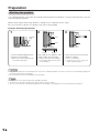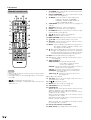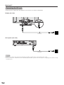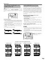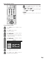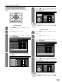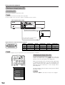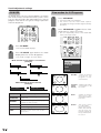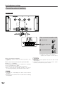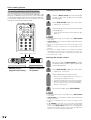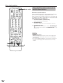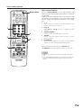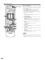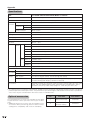
1
SHARP CORPORATION
Printed on post-consumer recycled paper.
Imprimé sur du papier recyclé.
Impreso en papel reciclado.
Impresso em papel reciclado pós utilização.
Printed in Japan
Imprimé au Japon
Impreso en Japón
Impresso no Japão
TINS-A529WJZZ A
03P02-JKG
MODE D’EMPLOI
MANUAL DE OPERAÇÃO
Sharp Plaza, Mahwah, New Jersey 07430-2135
OPERATION MANUAL
MODE D’EMPLOI
MANUAL DE OPERACIÓN
MANUAL DE OPERAÇÃO
ESPAÑOL
PORTUGUÊS
OPERATION MANUAL
MANUAL DE OPERACIÓN
SHARP ELECTRONICS CORPORATION
LIQUID CRYSTAL TELEVISION
TÉLÉVISEUR ACL
TELEVISOR CON PANTALLA DE
CRISTAL LIQUIDO
TELEVISOR DE CRISTAL LÍQUIDO
FRANÇAIS
ENGLISH
LC-37HV4U
LC-37HV4U
LIQUID CRYSTAL TELEVISION
ENGLISH
OPERATION MANUAL
IMPORTANT:
To aid reporting in case of loss or theft, please record
the TV’s model and serial numbers in the space
provided. The numbers are located at the rear of the
TV.
Model No.:
Serial No.:
IMPORTANT INFORMATION
WARNING: TO REDUCE THE RISK OF FIRE OR ELECTRIC SHOCK, DO
NOT EXPOSE THIS PRODUCT TO RAIN OR MOISTURE.
CAUTION
RISK OF ELECTRIC SHOCK
DO NOT OPEN
CAUTION: TO REDUCE THE RISK OF ELECTRIC SHOCK,
DO NOT REMOVE COVER (OR BACK).
NO USER-SERVICEABLE PARTS INSIDE.
REFER SERVICING TO QUALIFIED SERVICE
PERSONNEL.
The lightning flash with arrow-head
symbol, within an equilateral
triangle, is intended to alert the user
to the presence of uninsulated
“dangerous voltage” within the
product’s enclosure that may be of
sufficient magnitude to constitute a
risk of electric shock to persons.
The exclamation point within a
triangle is intended to alert the user
to the presence of important
operating and maintenance
(servicing) instructions in the
literature accompanying the product.
CAUTION:
This product satisfies FCC regulations when shielded cables and connectors are used to connect the unit to other
equipment. To prevent electromagnetic interference with electric appliances such as radios and televisions, use
shielded cables and connectors for connections.
ENGLISH
LC-37HV4U
IMPORTANT INFORMATION
CAUTION: TO PREVENT ELECTRIC SHOCK, MATCH WIDE BLADE OF PLUG TO
WIDE SLOT, FULLY INSERT.
CAUTION:
DO NOT PLACE THIS PRODUCT ON AN UNSTABLE CART, STAND, TRIPOD, BRACKET, OR
TABLE. THE PRODUCT MAY FALL CAUSING SERIOUS PERSONAL INJURY AND SERIOUS
DAMAGE TO THE PRODUCT. USE ONLY WITH A CART, STAND, TRIPOD, BRACKET, OR TABLE
RECOMMENDED BY THE MANUFACTURER OR SOLD WITH THE PRODUCT. FOLLOW THE
MANUFACTURER’S INSTRUCTIONS WHEN INSTALLING THE PRODUCT AND USE MOUNTING
ACCESSORIES RECOMMENDED BY THE MANUFACTURER. A PRODUCT AND CART
COMBINATION SHOULD BE MOVED WITH CARE. QUICK STOPS, EXCESSIVE FORCE, AND
UNEVEN SURFACES MAY CAUSE THE PRODUCT AND CART COMBINATION TO OVERTURN.
WARNING: FCC Regulations state that any unauthorized changes or modifications to this equipment not expressly
approved by the manufacturer could void the user’s authority to operate this equipment.
DECLARATION OF CONFORMITY
SHARP LIQUID CRYSTAL TELEVISION, MODEL LC-37HV4U.
This device complies with Part 15 of the FCC Rules. Operation is subject to the following two conditions:
(1) This device may not cause harmful interference, and (2) this device must accept any interference
received, including interference that may cause undesired operation.
RESPONSIBLE PARTY:
SHARP ELECTRONICS CORPORATION
Sharp Plaza, Mahwah, New Jersey 07430-2135
TEL: 1-800-BE-SHARP
For Business Customers: URL http://www. sharpusa. com
INFORMATION:
This equipment has been tested and found to comply with the limits for a Class B digital device, pursuant to
Part 15 of the FCC Rules. These limits are designed to provide reasonable protection against harmful
interference in a residential installation. This equipment generates, uses and can radiate radio frequency
energy and, if not installed and used in accordance with the instructions, may cause harmful interference to
radio communications. However, there is no guarantee that interference will not occur in a particular
installation. If this equipment does cause harmful interference to radio or television reception, which can be
determined by turning the equipment off and on, the user is encouraged to try to correct the interference by
one or more of the following measures:
—Reorient or relocate the receiving antenna.
—Increase the separation between the equipment and receiver.
—Connect the equipment into an outlet on a circuit different from that to which the receiver is connected.
—Consult the dealer or an experienced radio/TV technician for help.
“Note to CATV system installer: This reminder is provided to call the CATV system installer’s attention to Article 820-40 of the
National Electrical Code that provides guidelines for proper grounding and, in particular, specifies that the cable ground shall be
connected to the grounding system of the building, as close to the point of cable entry as practical.”
This product utilizes tin-lead solder, and fluorescent lamp containing a small amount of mercury. Disposal of these
materials may be regulated due to environmental considerations. For disposal or recycling information, please contact
your local authorities or the Electronic Industries Alliance: www.eia.org
2
DEAR SHARP CUSTOMER
Thank you for your purchase of the Sharp Liquid Crystal Television. To ensure safety and many years
of trouble-free operation of your product, please read the Important Safety Precautions carefully
before using this product.
IMPORTANT SAFETY PRECAUTIONS
Electricity is used to perform many useful functions, but it can also cause personal injuries and property damage if
improperly handled. This product has been engineered and manufactured with the highest priority on safety. However,
improper use can result in electric shock and/or fire. In order to prevent potential danger, please observe the following
instructions when installing, operating and cleaning the product. To ensure your safety and prolong the service life of
your Liquid Crystal Television, please read the following precautions carefully before using the product.
•
•
•
•
•
•
•
•
•
•
•
•
•
•
•
•
Read Instructions — All the safety and operating instructions should be read before the product is operated.
Retain Instructions — The safety and operating instructions should be retained for future reference.
Heed Warnings — All warnings on the product and in the operating instructions should be adhered to.
Follow Instructions — All operating and use instructions should be followed.
Attachments — Do not use attachments not recommended by the product manufacturer as they may cause
hazards.
Power Sources — This product should be operated only from the type of power source indicated on the marking
label. If you are not sure of the type of power supply to your home, consult your product dealer or local power
company. For products intended to operate from battery power, or other sources, refer to the operating
instructions.
AC Cord Protection — AC cords should be routed so that they are not likely to be walked on or pinched by items
placed upon or against them, paying particular attention to cords at plugs, convenience receptacles, and the
point where they exit from the product.
Overloading — Do not overload wall outlets, extension cords, or integral convenience receptacles as this can
result in a risk of fire or electric shock.
Object and Liquid Entry — Never push objects of any kind into this product through openings as they may touch
dangerous voltage points or short-out parts that could result in a fire or electric shock. Never spill liquid of any
kind on the product.
Servicing — Do not attempt to service this product yourself as opening or removing covers may expose you to
dangerous voltage or other hazards. Refer all servicing to qualified service personnel.
Damage Requiring Service — Unplug this product from the wall outlet and refer servicing to qualified service
personnel under the following conditions:
a) When the AC cord or plug is damaged,
b) If liquid has been spilled, or objects have fallen into the product,
c) If the product has been exposed to rain or water,
d) If the product does not operate normally by following the operating instructions.
Adjust only those controls that are covered by the operating instructions as an improper adjustment of
other controls may result in damage and will often require extensive work by a qualified technician to
restore the product to its normal operation,
e) If the product has been dropped or damaged in any way, and
f) When the product exhibits a distinct change in performance – this indicates a need for service.
Replacement Parts — When replacement parts are required, be sure the service technician has used
replacement parts specified by the manufacturer or have the same characteristics as the original part.
Unauthorized substitutions may result in fire, electric shock, or other hazards.
Safety Check — Upon completion of any service or repairs to this product, ask the service technician to perform
safety checks to determine that the product is in proper operating condition.
Wall or ceiling mounting — When mounting the product on a wall or ceiling, be sure to install the product
according to the method recommended by the manufacturer.
Polarization — The product may be equipped with a polarized alternating current line plug (a plug having one
blade wider than the other). This plug will fit into the AC outlet only one way.
This is a safety feature. If you are unable to insert the plug fully into the outlet, try reversing the plug. If the plug
should still fail to fit, contact your electrician to replace your obsolete outlet.
Do not defeat the safety purpose of the polarized plug.
Unplug the AC cord from the AC outlet before installing the speakers.
3
IMPORTANT SAFETY PRECAUTIONS
• Cleaning — Unplug this product from the wall outlet before cleaning. Do not use liquid cleaners
or aerosol cleaners. Use a damp cloth for cleaning.
• Water and Moisture — Do not use this product near water – for example, near a bath tub,
wash bowl, kitchen sink, or laundry tub; in a wet basement; or near a swimming pool; and the
like.
• Stand — Do not place the product on an unstable cart, stand, tripod or table. Placing the
product on an unstable base can cause the product to fall, resulting in serious personal
injuries as well as damage to the product. Use only a cart, stand, tripod, bracket or table
recommended by the manufacturer or sold with the product. When mounting the product on
a wall, be sure to follow the manufacturer’s instructions. Use only the mounting hardware
recommended by the manufacturer.
• A product and cart combination should be moved with care. Quick stops, excessive force,
and uneven surfaces may cause the product and cart combination to overturn.
• Ventilation — The vents and other openings in the cabinet are designed for ventilation. Do
not cover or block these vents and openings since insufficient ventilation can cause
overheating and/or shorten the life of the product. Do not place the product on a bed, sofa,
rug or other similar surface, since they can block ventilation openings. This product is not
designed for built-in installation; do not place the product in an enclosed place such as a
bookcase or rack, unless proper ventilation is provided or the manufacturer’s instructions are
followed.
• The Liquid Crystal panel used in this product is made of glass. Therefore, it can break when
the product is dropped or applied with impact. Be careful not to be injured by broken glass
pieces in case the panel breaks.
• Heat — The product should be situated away from heat sources such as radiators, heat
registers, stoves, or other products (including amplifiers) that produce heat.
• The Liquid Crystal panel is a very high technology product with 3,147,264 thin film transistors, giving you fine picture
details.
Occasionally, a few non-active pixels may appear on the screen as a fixed point of blue, green or red. Please note
that this does not affect the performance of your product.
Precautions when transporting the display
When transporting the display, never carry it by holding onto the speakers. Be sure to always carry the display by two
people holding it with two hands-one hand on each side of the display.
4
IMPORTANT SAFETY PRECAUTIONS
• Outdoor Antenna Grounding — If an outside antenna is connected to the television equipment, be sure the antenna
system is grounded so as to provide some protection against voltage surges and built-up static charges.
Article 810 of the National Electrical Code, ANSI/NFPA 70, provides information with regard to proper grounding of
the mast and supporting structure, grounding of the lead-in wire to an antenna discharge unit, size of grounding
conductors, Iocation of antenna-discharge unit, connection to grounding electrodes, and requirements for the
grounding electrode.
EXAMPLE OF ANTENNA GROUNDING AS PER
NATIONAL ELECTRICAL CODE, ANSI/NFPA 70
ANTENNA
LEAD IN
WIRE
GROUND
CLAMP
ELECTRIC
SERVICE
EQUIPMENT
NEC —NATIONAL ELECTRICAL CODE
ANTENNA
DISCHARGE UNIT
(NEC SECTION 810-20)
GROUNDING CONDUCTORS
(NEC SECTION 810-21)
GROUND CLAMPS
POWER SERVICE GROUNDING
ELECTRODE SYSTEM
(NEC ART 250, PART H)
• Lighting — For added protection for this television equipment during a lightning
storm, or when it is left unattended and unused for long periods of time, unplug it
from the wall outlet and disconnect the antenna. This will prevent damage to the
equipment due to lightning and power-line surges.
• Power Lines — An outside antenna system should not be located in the vicinity of
overhead power lines or other electric light or power circuits, or where it can fall
into such power lines or circuits. When installing an outside antenna system, extreme
care should be taken to keep from touching such power lines or circuits as contact
with them might be fatal.
5
Contents
IMPORTANT INFORMATION ……………………… 1
DEAR SHARP CUSTOMER ………………………… 3
IMPORTANT SAFETY PRECAUTIONS …………… 3
Contents ……………………………………………… 6
Supplied accessories ……………………………… 7
Preparation …………………………………………… 8
Attaching the speakers ………………………… 8
Where to place the System ……………………… 9
Setting the System …………………………… 10
Setting the Display on the wall ……………… 12
Setting the AVC System with the stand ……… 12
Inserting the batteries ………………………… 13
Using the remote control unit ………………… 13
Cautions regarding remote control unit … 13
Part names ………………………………………… 14
Display ………………………………………… 14
AVC System …………………………………… 15
Remote control unit …………………………… 16
Watching TV ……………………………………… 17
Antennas ……………………………………… 17
Cable converter/VCR connection …………… 17
Outdoor antenna connection ………………… 19
Connecting the AC cord ……………………… 20
Turning on the power ………………………… 21
Turning off the power ………………………… 21
Initial setup ……………………………………… 22
Simple button operations
for changing channels …………………… 23
Simple button operations
for changing volume/sound ……………… 24
Using FRONT SURROUND
on the remote control unit ………………… 25
Setting MTS/SAP stereo mode ……………… 25
Basic adjustment settings ……………………… 26
AV input mode menu items …………………… 26
PC input mode menu items …………………… 26
EZ setup ………………………………………… 27
Channel setup ………………………………… 28
Language setting ……………………………… 31
Picture adjustments …………………………… 32
C.M.S. (Color Management System) …… 33
Color temperature ………………………… 34
Black ……………………………………… 34
3D-Y/C ……………………………………… 35
Monochrome ……………………………… 35
Film mode (3:2 pull-down) ……………… 36
I/P Setting ………………………………… 36
Sound adjustment ……………………………… 37
Power control …………………………………… 38
Power control for AV source ……………… 38
Power control for PC source ……………… 40
6
Using external equipment ………………………
Watching a DVD image ………………………
Connecting a DVD player …………………
Displaying a DVD image …………………
Watching a VCR image ………………………
Connecting a VCR …………………………
Displaying a VCR image …………………
Watching broadcasts via a Digital TV tuner …
Connecting a Digital TV tuner ……………
Displaying broadcasts
via a Digital TV tuner …………………
Enjoying a game console
or viewing camcorder images ……………
Connecting a game console
or camcorder …………………………
Displaying an image of the game
console or camcorder ………………
Viewing an image from a PC …………………
Connecting a PC …………………………
Displaying an image from a PC …………
Useful adjustment settings ………………………
Image position (AV input mode only) ………
Moving the picture on the screen ……………
Auto Sync. adjustment (PC input mode only) …
Fine Sync. adjustment (PC input mode only) …
Input signal source ……………………………
Picture flip ………………………………………
AV MODE ………………………………………
View modes for 4:3 Programs …………………
View mode (for PC input mode) ………………
Input signal (for PC input mode) ……………
Noise clean ……………………………………
Sleep timer ………………………………………
Audio out ………………………………………
Connecting external speakers ………………
Selecting speakers ………………………
Cool climate ……………………………………
Closed caption …………………………………
Secret number setting for parental control
(AV input mode only) ………………………
Parental control (setting V-CHIP level) ………
How to temporarily release
the V-CHIP BLOCK ………………………
Reactivating the temporarily released
V-CHIP BLOCK ……………………………
Other viewing options ……………………………
Twin picture functions …………………………
Learning remote control function ……………
Using the TV remote control unit
to control other devices ……………………
Appendix …………………………………………
Troubleshooting …………………………………
PC compatibility chart …………………………
RS-232C port specifications …………………
Specifications …………………………………
Optional accessories …………………………
Dimensional drawings ……………………………
41
42
42
42
43
43
43
44
44
44
45
45
45
46
46
46
47
47
48
49
49
50
51
52
52
53
54
54
55
55
56
57
58
59
60
62
66
66
67
67
68
70
76
76
77
78
80
80
81
Supplied accessories
Make sure the following accessories are provided with the product.
“AA” size Alkaline battery (g2)
Cable clamp (Large g1, Small g2)
RRMCGA037WJSA
Page 13
UBATA0018CEZZ
Page 13
LHLDW0110CEZZ (Large)
LHLDZ0139CEZZ (Small)
Page 11
Stand unit (for AVC System) (g1)
Speaker unit (g1)
System cable (g1)
Remote control unit (g1)
TV
TV
CBL VCR DVD
/SAT
/LD
/DTV
POWER
ANT-A/B
AV
FRONT
MODE
SURROUND
INPUT
MTS
CC
TWIN
PICTURE
SELECT
MODE
FREEZE
INPUT
DISPLAY
SLEEP
SUB
VIEW
TWIN CH
EDIT/
LEARN
1
2
4
5
7
8
9
0
100
ⴐ
3
6
VOL
CH
ⴑ
MENU
ENT
FLASHBACK
MUTE
TV/SAT/DVD
RETURN
DTV/DVD TOP
MENU
MENU
SOURCE
DTV/SAT
POWER
GUIDE
SET/
ENTER
DTV/SAT
INFO
VCR REC
FAVORITE CH
A
B
POWER
INPUT
C
D
VOLⴑ
VOLⴐ
RECEIVER
GDAI-A059WJSA
QCNW-6117CEZZ
Page 10
PSPAHA101WJZZ
RSP-ZA027WJN1 (Left)
RSP-ZA027WJN2 (Right)
AC cord (g2)
GLEGGA013WJZZ
XBBSF40P25000
XBPSN40P14JS0
Stand (g1)
Stand cushion (g4)
Stand spacer (g4)
Stand screw (g2)
Speaker (Lg1, Rg1)
Speaker screw (g4)
Page 12
Page 8
Operation manual (g1)
RF cable (g1)
LC-37HV4U
TINS-A529WJZZ
QCNW-A342WJZZ
Pages 18 and 19
(for Display)
QACCDA019WJPZ
(for AVC System)
QACCD3097CEPZ
Page 10
NOTE
• Always use the AC cord supplied with
the Liquid Crystal Television and the
one supplied with the AVC System for
each respective unit.
• AC cords enclosed in this product are
for 110-125V. In using it on the 125240V AC, please consult to the
following.
SHARP ELECTRONICS
CORPORATION
1300 Naperville Drive, Romeoville,
Illinois 60446-1091, U.S.A. TEL: 630226-2400
7
Preparation
Attaching the speakers
The supplied speaker unit can be attached to or detached from the Display. It must be attached unless you use
external amplifier/speakers.
Before attaching (or detaching) speakers, unplug the AC cord from the AC outlet.
Be sure to attach or detach the speakers with two or more people.
Example: Attaching right speaker.
1
2
3
Speaker
plug
Hole
Hole
Bulge
Bulge
Insert the speaker plug into the
terminal on the Display.
Take hold of the speaker and
slowly slide it to the Display.
Fasten the screws to secure the
speaker in place.
• Make sure that the speaker plug
is inserted completely.
• Make sure that the two bulges of
the speaker align with the holes
on the Display.
• Use a screwdriver.
• Perform the same steps for
attaching left speaker.
CAUTION
• The speaker terminals on the Display are only for the supplied speaker unit. Do not connect any third party plug to the
terminal or speaker to the Display.
• Do not handle or move the Display by the speakers.
NOTE
• Perform the same steps for both left and right speakers.
• To detach the speakers, perform the above steps in reverse order.
• You can connect your own amplifier/speakers to the Display. See page 56 for connecting external speakers.
8
Preparation
Where to place the System
“System” means the Display and AVC System. First select the location where to place the System.
1
Selecting the location of the System
• Select a place with no direct sunlight and good ventilation.
• The Display and the AVC System are connected by the system cable.
(See page 10 for details.)
System cable
Display
2
If you want to keep a longer distance between
the Display and AVC System, please purchase
the optional system cable AN-07SC1 (about 23
feet/7 meters). (See page 80.)
AVC System
Setting the System in place
Handling the Display
CAUTION
• The Display is very heavy. Move it with two or more people.
• Do not remove the stand from the Display unless using an
optional bracket to mount it.
• When moving, put your hands on the Display, but never on the
Display speakers.
• Keep enough space above and behind the Display.
Handling the AVC System
CAUTION
CAUTION
• Do not put a VCR or other device on the AVC System.
• Keep enough space above and on the sides of the AVC System.
• Do not block the ventilation openings on the top and left side,
and the exhaust fan on the right side.
• Do not spread a thick cloth beneath the AVC System, or cover it
with one, as this can cause overheating and result in malfunction.
Adjust the screen with both
hands. Put one hand on the
Display and tilt the screen
while steadying the stand
with your other hand.
You can adjust the screen
vertically up to 4 degrees
forward or 6 degrees backward, or rotate 10 degrees
horizontally.
4 inches
10 cm)
cm
(10
or more
Keep enough space
inches
(5
52cm
or more
cm) or more
2 inches (5
cm) or more
5 cm
orsides
more
on
both
There is an exhaust
fan on the right side.
9
Preparation
Setting the System
After putting the Display and the AVC System in place, connect the system cables and AC cords. Use the
cable clamps for bundling the cables.
1
Removing the terminal cover
Display (rear view)
Press the two hooks
toward the center of the
Display and remove the
cover toward you.
Press down the two
upper hooks to remove
the cover toward you.
2
Connecting the system cable and the AC cord to the Display
DISPLAY INPUT1
AC cord
3
DISPLAY INPUT2
(WHITE)
Connect the plug into
the terminal and secure System cable
it by tightening the
thumb screws.
(GRAY)
Connect the plug firmly
until the hooks on both
sides click.
Connecting the system cable and the AC cord to the AVC System
System cable
(GRAY)
(WHITE)
AVC System (rear view)
AC cord
CAUTION
10
• TO PREVENT RISK OF ELECTRIC SHOCK, DO NOT TOUCH UN-INSULATED PARTS OF ANY CABLES WITH THE
AC CORD CONNECTED.
Preparation
4
Attaching the clamps and bundling the cables with the clamp
Cable clamp (Large)
Cable clamp (Small)
Insert the cable
clamp in the hole
on the Display leg
as shown.
Peel off the seal
on the back and
attach as shown.
Display (rear view)
NOTE
• The small clamp on the right is used for
bundling external speakers. (See page 56.)
5
Closing the terminal cover
Cables come
out from the
small opening.
11
Preparation
Setting the Display on the wall
Using an optional bracket to mount the Display
• You can ask a qualified service personnel about using an optional AN-37AG1 bracket to mount the Display
to the wall.
• Carefully read the instructions that come with the bracket before beginning work.
Hanging on the wall
AN-37AG1 wall mount bracket. (See the bracket instructions for details.)
Vertical mounting
Angular mounting
CAUTION
• Installing the Liquid Crystal Television requires special skill that should only be performed by qualified service personnel.
Customers should not attempt to do the work themselves. SHARP bears no responsibility for improper mounting or
mounting that results in accident or injury.
Setting the AVC System with the stand
How to install the AVC System vertically using the stand unit.
• Use the supplied stand unit for installing the AVC System vertically in an upright position.
1
Stick each spacer to the
stand as shown.
Peel each spacer
away from the
paper and attach
to the four bulging
areas on the stand.
Stand
spacer
Bulge
Bulge
4
2
Attach each cushion to
the stand as shown.
Peel each cushion
away from the
paper and attach
to the four areas at
the bottom.
Stand cushion
Attaching point
Attaching point
Attach the stand using the
stand screws as shown.
3
Fit the stand to the AVC
System.
Insert the stand into the AVC
System, making sure that the
thick and thin bulges of the
stand align with the big and
small holes on the AVC
System.
Thin bulge
Small
hole
Big hole
Thick
bulge
The AVC System installed
vertically with the stand.
Stand screw
NOTE
• When mounting the AVC System vertically, always use the supplied stand. Be careful not to block vent holes when
standing up directly on the floor or a flat surface as this can result in equipment failure.
12
Preparation
Inserting the batteries
If the remote control fails to operate Liquid Crystal Television functions, replace the batteries in the remote
control unit.
1 Open the battery cover.
2 Insert two “AA” size Alkaline 3 Close the battery cover.
batteries (supplied with the
product).
_
+
+
_
• Place the batteries with their terminals
corresponding to the (e) and (f)
indications in the battery compartment.
CAUTION
Improper use of batteries can result in chemical leakage or explosion. Be sure to follow the instructions below.
• Do not use manganese batteries. When you replace the batteries, use alkaline ones.
• Place the batteries with their terminals corresponding to the (e) and (f) indications.
• Do not mix batteries of different types. Different types of batteries have different characteristics.
• Do not mix old and new batteries. Mixing old and new batteries can shorten the life of new batteries or cause
chemical leakage in old batteries.
• Remove batteries as soon as they are worn out. Chemicals that leak from batteries can cause a rash. If you
find any chemical leakage, wipe thoroughly with a cloth.
• The batteries supplied with this product may have a shorter life expectancy due to storage conditions.
• If you will not be using the remote control unit for an extended period of time, remove batteries from it.
Using the remote control unit
Use the remote control unit by pointing it towards the remote control sensor on
the Display. Objects between the remote control unit and the remote control
sensor may prevent proper operation.
Cautions regarding remote control unit
• Do not expose the remote control unit to shock.
In addition, do not expose the remote control unit to liquids, and do not place
in an area with high humidity.
• Do not install or place the remote control unit under direct sunlight.
The heat may cause deformation of the remote control unit.
• The remote control unit may not work properly if the remote control sensor on
the Display is under direct sunlight or strong lighting. In such cases, change
the angle of the lighting or the Display, or operate the remote control unit
closer to the remote control sensor.
13
Part names
Display
INPUT
button
VOLUME buttons
(VOLl/k )
CHANNEL buttons
(CHs/r)
MAIN POWER
button
POWER button
Remote control sensor
OPC sensor
OPC indicator*
POWER indicator
14
*OPC: Optical Picture Control
(See pages 38 and 40.)
Part names
AVC System
PC INPUT terminal (AUDIO)
PC INPUT terminal (ANALOG RGB)
Front view
Headphone
(When connecting headphones, the sound from the
speakers is muted.)
How to open the door.
INPUT 4 terminals (AUDIO L/R)
STANDBY/ON indicator
MAIN POWER button
INPUT 4 terminal (VIDEO)
CLEAR*
INPUT 4 terminal (S-VIDEO)
* If the AVC System is switched on but it does not appear to be operating correctly, it may need resetting. In this
case, press CLEAR, shown in the diagram, lightly with the end of a ballpoint pen or other pointed object.
This will reset the System as shown below.
•
•
•
•
•
•
AV MODE resets to USER
TV channel returns to initial channel setting (Air:2ch, Cable:1 or 2ch)
Twin picture resets to normal
Audio setting initializes
SRS resets to off
Image position initializes
NOTE
• Pressing CLEAR will not work if the System is in standby mode (indicator lights red).
• Pressing CLEAR will not delete channel preset or secret number. See page 61 for clearing the secret number when you
know it. See page 83 for initializing to the factory preset values when you forget your secret number.
DC OUTPUT terminal
(Terminal for expanded functionality in
the near future.)
Rear view
Antenna (A) input terminal
Antenna (A) output
terminal
Antenna (B)
input terminal
DVI-DIGITAL
INPUT
terminal
INPUT 1 terminal (S-VIDEO)
INPUT 1 COMPONENT
video terminals (Y, PB, PR)
INPUT 1 terminal
(VIDEO)
INPUT 1 terminals
(AUDIO L/R)
INPUT 2 terminals
(AUDIO L/R)
INPUT 2 terminal (VIDEO)
INPUT 2 terminal (S-VIDEO)
DISPLAY OUTPUT 2 terminal
DISPLAY OUTPUT 1 terminal
RS-232C
terminal
AC INPUT terminal
INPUT 3 COMPONENT
video terminals (Y, PB, PR)
INPUT 3 terminals (AUDIO L/R)
INPUT 3 terminal (S-VIDEO)
INPUT 3 terminal (VIDEO)
MONITOR OUTPUT terminal
(S-VIDEO)
MONITOR OUTPUT
terminal (VIDEO)
MONITOR OUTPUT terminals (AUDIO L/R)
15
Part names
Remote control unit
1
2
24
25
1 12 13
14
2
3
TV
TV
15
CBL VCR DVD
/SAT
/LD
/DTV
POWER
ANT-A/B
AV
FRONT
MODE
SURROUND
3
INPUT
CC
16
TWIN CH
17
MTS
4
TWIN
4
5
PICTURE
SELECT
MODE
FREEZE
INPUT
DISPLAY
SLEEP
VIEW
6
7
8
9
10
SUB
EDIT/
LEARN
1
2
3
4
5
6
7
8
9
0
100
ⴐ
18
ENT
19
5
6
7
8
9
10
11
12
FLASHBACK
VOL
CH
ⴑ
MUTE
20
13
21
MENU
TV/SAT/DVD
DTV/DVD TOP
RETURN
MENU
MENU
SOURCE
DTV/SAT
POWER
GUIDE
11
SET/
ENTER
DTV/SAT
14
22
INFO
FAVORITE CH
A
B
POWER
INPUT
VCR REC
C
D
VOLⴑ
VOLⴐ
23
15
16
RECEIVER
17
NOTE
• When using the remote control unit, point it at the Liquid
Crystal Television.
• See pages 68 to 75 for operating buttons not listed on
this page.
*
is a trademark of SRS Labs, Inc.
FOCUS technology is incorporated under license from
SRS Labs, Inc.
18
19
20
21
22
23
TV POWER: Switch the Liquid Crystal Television power
on or off. (See page 21.)
FRONT SURROUND: Set SRS* and FOCUS* Sound
System mode. (See page 25.)
AV MODE: Select an audio or video setting. (See
page 52.) (AV mode: STANDARD,
DYNAMIC, MOVIE, GAME, USER. PC
mode: STANDARD, USER.)
VIEW MODE: Select the screen size. (See pages 52
and 53.)
DISPLAY: Display the channel information.
SLEEP: Set the sleep timer. (See page 55.)
FLASHBACK: Return to the previous channel or input
external mode. (See page 23.)
l: Set the volume. (See page 24.)
VOL k/l
MENU: Display the menu screen.
MENU RETURN: Return to the previous menu screen.
a/b/c/d: Select a desired item on the screen.
ANT-A/B: Select between ANT-A and B to watch
broadcasts via the two tuners.
INPUT: Select a Liquid Crystal Television input source.
(TV, INPUT 1, INPUT 2, INPUT 3, INPUT 4, PC)
(See pages 42–46 and 50.)
: When pressed all buttons on the remote control unit
will light. The lighting will turn off if no operations
are performed within about 5 seconds. This button
is used for performing operations in dark places.
MTS: Select the MTS/SAP. (See page 25.)
CC: Display captions during closed-caption source.
(See page 59.)
TWIN CH buttons
TWIN PICTURE: Set the twin picture mode.
Press again to return to normal
screen. (See page 67.)
FREEZE: Set the still image. Press again to return to
normal screen. (See page 67.)
SELECT: Select the active screen. (See page 67.)
SUB INPUT: Select an input source of sub screen.
(See page 67.)
TWIN CH a/b: Select the channel of sub screen.
(See page 67.)
0 – 9: Set the channel.
100 ENT: Select the three digit mode. Execute a
command of the channel.
b: Select the channel.
CH a/b
MUTE: Mute the sound. (See page 24.)
SET/ENTER: Execute a command.
FAVORITE CH
A, B, C, D: Select four preset favorite channels in four
different categories. (See page 30 for details.)
When viewing via ANT-A: up to 16 channels can be
assigned in A, B, C and D.
When viewing via ANT-B: up to 16 channels can be
assigned in A, B, C and D.
With ANT-A and B combined, you can preset up to 32
favorite channels in advance.
While watching, you can toggle the selected channels
by pressing A, B, C and D.
24 LED for transmission confirmation
25 Mode switch: (See pages 68 to 75 for details.)
16
Watching TV
Simple operations for watching a TV program
Antennas
To enjoy a clearer picture, use an outdoor antenna. The following is a brief explanation of the types of connections
that are used for a coaxial cable. If your outdoor antenna uses a 75-ohm coaxial cable with an F-type connector,
plug it into the antenna terminal at the rear of the AVC System.
NOTE
• The antenna and the cable converter cannot be connected at the same time.
F-type connector
1. A 75-ohm system is generally a round cable with F-type
connector that can easily be attached to a terminal without
tools (not supplied).
75-ohm coaxial cable (round)
2. A 300-ohm system is a flat “twin-lead” cable that can be
attached to a 75-ohm terminal through a 300/75-ohm
adapter (not supplied).
300-ohm twin-lead cable (flat)
Cable converter/VCR connection
• Be sure to connect the antenna or the cable converter as follows. Signal reception may fail if improperly connected.
• Be sure to remember what kind of connection is made with your System.
• The connection type will determine whether to select “Air” or “Cable” for both ANT-A and B when configuring “Air/Cable”
settings.
A-1. Connecting with Converter/Descrambler Box and VCR
Coaxial Antenna Cable (commercially available)
Coaxial Antenna Cable (commercially available)
Rear Terminals
OUT
2-way
signal
splitter
(not
supplied) Cable lead-in
IN
Cable TV converter
(not supplied)
Coaxial Antenna Cable (commercially available)
VCR
S-VIDEO VIDEO AUDIO
OUT
IN
Video Cable (commercially available)
Audio Cable (commercially available)
S-video Cable (commercially available)
NOTE
• Be sure to remember what kind of connection is made with your System.
• Shown here is the preferred method of connecting a VCR and CATV Converter to your TV if you are in an area with good
signal reception. This way you can view either TV programs or VCR tapes and not be concerned about the position of the
VCR’s TV/VCR switch and you can enjoy stereo tape playback from a stereo VCR.
• If your VCR has an S-Video terminal, S-video connection is recommended.
17
Watching TV
Cable converter/VCR connection (continued)
A-2. Connecting with cable converter using AUX terminals for audio and video output.
(If your cable TV converter has both RF OUTPUT and AUX terminals, it is recommended to connect it as
shown in example A-1.)
RF
Cable
(Supplied)
Coaxial Antenna Cable (commercially available)
Rear Terminals
OUT
2-way
signal
splitter
(not
supplied)
IN
VIDEO AUDIO
Cable lead-in
Cable TV converter
(not supplied)
VCR
S-VIDEO VIDEO AUDIO
OUT
IN
Video Cable
(commercially available)
Audio Cable
(commercially available)
S-video Cable (commercially available)
NOTE
• Be sure to remember what kind of connection is made with your System.
• Shown here is the preferred method of connecting a VCR and CATV Converter to your TV if you are in an area with good
signal reception. This way you can view either TV programs or VCR tapes and not be concerned about the position of the
VCR’s TV/VCR switch and you can enjoy stereo tape playback from a stereo VCR.
• If your VCR has an S-Video terminal, S-video connection is recommended.
B.
Connecting with Converter/Descrambler Box without VCR
Coaxial Antenna Cable (commercially available)
Coaxial Antenna Cable (commercially available)
Rear Terminals
OUT
IN
Cable TV converter
(not supplied)
2-way
signal
splitter
(not
supplied) Cable lead-in
Coaxial Antenna Cable (commercially available)
NOTE
• Be sure to remember what kind of connection is made with your System.
• Switching between Antenna-A and Antenna-B is possible by pressing the ANT-A/B button on the remote control.
• A good color picture depends on a good TV signal. So does good multi-channel sound. Ask your dealer for advice on
how to install your outdoor antenna to receive the best possible signal.
• If you subscribe to Cable TV or have a central antenna for your building, you may not need an outdoor antenna.
18
Watching TV
C.
Connecting Antenna Cable with VCR
RF Cable
(Supplied)
Coaxial Antenna Cable (commercially available)
Rear Terminals
2-way
signal
splitter
(not
supplied) Cable lead-in
Coaxial Antenna Cable
(commercially available)
VCR
S-VIDEO VIDEO AUDIO
OUT
IN
Video Cable (commercially available)
Audio Cable (commercially available)
S-video Cable (commercially available)
NOTE
• Be sure to remember what kind of connection is made with your System.
• Shown here is the preferred method of connecting a VCR to your TV if you are in an area with good signal reception. This
way you can view either TV programs or VCR tapes and not be concerned about the position of the VCR’s TV/VCR switch
and you can enjoy stereo tape playback from stereo VCR.
• If your VCR has an S-Video terminal, S-video connection is recommended.
• If your lead cable is a 300-ohm twin-lead cable or UHF/VHF separate cable, use a 300/75-ohm adapter or combiner
(output side is 75-ohm coaxial) to connect to the TV (see below).
Outdoor antenna connection
Connecting Antenna Cable
Cable without a CATV
converter
Home Antenna
terminal (75-ohm)
Cable TV lead-In
Combination
VHF/UHF antenna
or 75-ohm coaxial cable (round)
300-ohm twin-lead (flat)
Coaxial cable
(commercially
available)
RF Cable (Supplied)
300/75-ohm adapter
(commercially available)
VHF
UHF
ANTENNA ANTENNA
Separate VHF/UHF
antenna
300-ohm
twin-lead
300-ohm twin-lead
Combiner
(commercially
available)
IN OUT
or
75-ohm coaxial cable
NOTICE
F-type connector
75-ohm coaxial cable
F-type connector should be finger-tightened only.
When connecting the RF cable to the TV set,
do not tighten F-type connector with tools.
If tools are used, it may cause damage to your
TV set.
(The breaking of internal circuit, etc.)
19
Watching TV
Connecting the AC cord
Connect the AC cords after all component connections have been completed.
Display (rear view)
AC cord
AVC System (rear view)
AC cord
NOTE
• Always turn off the main power of the Display and AVC System when connecting the AC cords.
• Disconnect the AC cords from the AC outlet, Display and AVC System when the System is not going to be used for a long
period of time.
20
Watching TV
Turning on the power
Display
1
Press MAIN POWER on the Display.
• The POWER indicator on the Display flashes red.
POWER button
MAIN POWER
2
Press MAIN POWER on the AVC System.
• The System turns the power on.
• The POWER indicator on the Display lights up green and the
STANDBY/ON indicator on the AVC System lights up green.
• If the STANDBY/ON indicator on the AVC System and the POWER
indicator on the Display still light up red, press TV POWER on
the remote control unit or MAIN POWER on the AVC System to
turn the System on.
POWER indicator
First time turning on the AVC System
1
2
TV
NOTE
CBL VCR DVD
/SAT
/LD
/DTV
POWER
ANT-A/B
AV
FRONT
MODE
SURROUND
Press MAIN POWER on the Display.
• The System turns the power on.
• The POWER indicator on the Display lights up green and the
STANDBY/ON indicator on the AVC System lights up green.
• If the STANDBY/ON indicator on the AVC System and the
POWER indicator on the Display still light up red, press TV
POWER on the remote control unit or POWER button on the
Display to turn the System on.
MAIN
STANDBY/ON indicator
POWER
TV
Press MAIN POWER on the AVC System.
• The STANDBY/ON indicator on the AVC System lights up red.
AVC System
• The initial setup starts when the System powers on for the first time. If the
System has been turned on before, the EZ setup will not be invoked. See
page 27 to try EZ setup from the Setup menu.
INPUT
MTS
CC
TWIN
PICTURE
SELECT
MODE
FREEZE
INPUT
DISPLAY
SLEEP
SUB
VIEW
TWIN CH
EDIT/
LEARN
1
2
3
4
5
6
7
8
9
0
100
Turning off the power
1
Press TV POWER on the remote control unit or
POWER button on the Display.
• The System enters standby mode and the image on the screen
disappears.
• Both the STANDBY/ON indicator on the AVC System and the
POWER indicator on the Display change from green to red.
ENT
2
Press MAIN POWER on the AVC System.
• The STANDBY/ON indicator on the AVC System turns off and
the POWER indicator on the Display flashes red.
3
Press MAIN POWER on the Display.
• The POWER indicator on the Display gradually turns off.
NOTE
Display status indicator
• If you are not going to use this System for a long period of time, be sure to
remove the AC cords from the power outlet.
• When the STANDBY/ON indicator lights up red, it takes about 10 to 15
seconds for the indicator to turn off if MAIN POWER on the AVC System is
turned “Off” or the AC cord is unplugged from the AC outlet.
Off
Power off
Flashing red
AVC System does not turn on or its AC cord is disconnected.
Red
The System is in standby mode.
Green
The System is on.
AVC System status indicator
Off
Power off
Red
Only the AVC System is in standby mode or the System is in standby mode.
Green
The System is on.
21
Watching TV
Initial setup
When you turn on the System for the first time, it will automatically memorize the broadcasting channels where
you live. Perform the following steps before you press TV POWER on the remote control unit.
1. Insert the batteries into the remote control unit. (See page 13.)
2. Connect the antenna cable to the AVC System. (See pages 17 to 19.)
3. Plug in the AC cord to the AC outlet. (See page 20.)
Language setting
Select from among 3 languages: English, French and
Spanish.
MENU
TV/SAT/DVD
RETURN
MENU
DTV/DVD TOP
MENU
SOURCE
DTV/SAT
GUIDE
POWER
1
SET/
ENTER
Press a/b to select the desired language
listed on the screen, and then press SET/
ENTER.
DTV/SAT
INFO
VCR REC
FAVORITE CH
Setup
EZ Setup - Language
A
B
C
D
POWER
INPUT
VOLⴑ
VOLⴐ
RECEIVER
English
Français
Español
Channel search
Channel auto search makes the System look for all
channels viewable in the set area.
3
Antenna setting
Example
NOTE
CH Search
• Make sure what kind of connection is made with your
System when selecting “Air” or “Cable” for both ANT-A
and B.
2
ANT-A
Press c/d to select “Air” or “Cable” for ANTA, then press a/b to move down.
Press c/d to select “Air” or “Cable” for ANTB.
Press SET/ENTER to enter the setting.
[
2]
[
2]
CH Search
ANT-B
• This operation makes the System search for
both ANT-A and B.
2
Example
Setup
Cable
ANT-A
Noise Clean
EZ Setup - Air/Cable
ANT-A
Air
Cable
ANT-B
Air
Cable
Setup
EZ Setup - Air/Cable
22
Air
ANT-A
Air
Cable
ANT-B
Air
Cable
NOTE
• Make sure what kind of connection is made with your
System when selecting “Air” or “Cable” for both ANT-A
and B.
• If no channel is found, make sure what kind of connection
is made with your System and try EZ setup again (see
page 27).
• The illustrations and on-screen displays in this operation
manual are for explanation purposes and may vary slightly
from the actual operations.
Watching TV
Simple button operations for
changing channels
You can change channels in several ways.
NOTE
• While watching a broadcast, press ANT-A/B to view the
image received from the other tuner.
TV
TV
CBL VCR DVD
/SAT
/LD
/DTV
POWER
ANT-A/B
AV
FRONT
MODE
SURROUND
CC
TWIN
PICTURE
SELECT
MODE
FREEZE
INPUT
DISPLAY
SLEEP
SUB
VIEW
TWIN CH
EDIT/
LEARN
1
2
3
4
5
6
7
8
9
0
100
ⴐ
NOTE
• FLASHBACK will not work if no channel has been
changed after the System is turned on.
Select the channels directly by pressing buttons 0 to
9 and 100.
• The System allows you to select up to 125 channels
(1 to 125). To select a channel, enter a 2 or 3-digit
number.
a
To select a 1 or 2-digit channel number
(e.g., Channel 5):
Complete the following steps within 3 seconds.
1
Press the 0 button.
• Complete the step 2 within 3 seconds after the
step 1.
ENT
FLASHBACK
VOL
ⴑ
Press FLASHBACK to switch the currently tuned
channel to the previously tuned channel.
Press FLASHBACK again to switch back to the
currently tuned channel.
Using 0 – 9 and 100 on the remote control
unit
INPUT
MTS
Using FLASHBACK on the remote control
unit
CH
2
Press the 5 button.
0–
MUTE
Using CHa/b on the remote control unit
• Press CHa
a to increase the channel number.
b to decrease the channel number.
• Press CHb
NOTE
a/b
b
• CH s/r on the Display operates the same as CHa
on the remote control unit.
Display
• When selecting a 1-digit channel number, do not fail to
press the 0 button.
To select a 3-digit channel number
(e.g., Channel 115):
Complete the following steps within 3 seconds.
1
Press the 1 button.
• Complete the step 3 within 3 seconds after the
step 2.
CH s/r
Press CH a and the channel change in the
order shown below:
2s3s...s68s69s2s3...
Press CH b and the channel change in the order
shown below:
3s2s69s68s...s3s2...
Cable:Press CH a and the channel change in the
order shown below:
1s2s3s...s125s1s2s3...
Press CH b and the channel change in the order
shown below:
3s2s1s125s...s3s2s1s...
Press the 100 button.
• Complete the step 2 within 3 seconds after the
step 1.
2
Changing channels with CH a/b on the
remote control unit or CH s/r on the
Display
5
NOTE
3
Press the 5 button.
1––
11 –
Air:
115
NOTE
• The 100 button is only enabled when selecting channels
in Cable mode.
23
Watching TV
Using MUTE on the remote control unit
Simple button operations for
changing volume/sound
Mutes the current sound output.
Changing the volume
You can change the volume on the Display or on the
remote control unit.
TV
TV
Display
CBL VCR DVD
/SAT
/LD
/DTV
POWER
ANT-A/B
AV
FRONT
MODE
SURROUND
INPUT
MTS
CC
TWIN
PICTURE
SELECT
MODE
FREEZE
INPUT
DISPLAY
SLEEP
VIEW
SUB
TWIN CH
EDIT/
LEARN
VOL l/k
ⴐ
VOL
ⴑ
1
2
3
4
5
6
7
8
9
0
100
FLASHBACK
CH
MUTE
MENU
TV/SAT/DVD
DTV/DVD TOP
RETURN
MENU
MENU
ⴐ
l on the remote control unit
Using VOL k/l
FLASHBACK
CH
VOL
• To increase the volume, press VOL k.
• To decrease the volume, press VOL l.
ⴑ
Volume adjustment
1
ENT
MUTE
MENU
TV/SAT/DVD
DTV/DVD TOP
RETURN
MENU
MENU
Press MUTE.
• “M” has been displayed on the screen for 30
minutes, and the sound is silenced.
20
Mute
NOTE
kon the Display operates the same as VOL k/l
l
• VOL l/k
on the remote control unit.
0
Audio status
Audio out
Output device
Fixed
Variable
Speaker
Variable sound
Mute
MONITOR OUT
Constant as
specified
Variable sound
* When “Audio Out” is set to “Variable”, the indicator on the
screen changes as shown below.
20
NOTE
NOTE
• Within 30 minutes of pressing MUTE, mute can be
canceled by using one of the methods below.
• Pressing VOL l/k on the Display or VOL k/l, MTS
or MUTE on the remote control unit can also cancel the
mute.
• Mute will be canceled after 30 minutes have passed.
However, the System will not suddenly output a loud
sound as the volume level is set to 0 automatically.
• See page 55 for details on the audio out function.
2
Within 30 minutes, press MUTE again to
cancel the mute.
• Before 30 minutes, the volume level returns to
the previous setting.
• After 30 minutes, increase the volume level by
pressing VOL k.
24
Watching TV
Using FRONT SURROUND on the
remote control unit
h produces SRS and FOCUS effects from the
speakers.
Each time you press FRONT SURROUND, the mode
changes among SRS, FOCUS, FOCUS e SRS and
Off.
TV
TV
CBL VCR DVD
/SAT
/LD
/DTV
POWER
ANT-A/B
AV
FRONT
MODE
SURROUND
CC
TWIN
PICTURE
SELECT
SRS sound options
• SRS (Sound Retrieval System): Creates more a
natural sound retrieving the spatial information from
any stereo recording and restoring the original threedimensional sound field.
• FOCUS: Repositions a sound image from two
speakers to a more optimal listening position or
height without moving them.
• FOCUS e SRS: Produces both SRS and FOCUS
effects.
• Off: Outputs the normal sound.
: Off
: SRS
: FOCUS+SRS
: FOCUS
The System has a feature that allows reception of
sound other than the main audio for the program. This
feature is called Multi-channel Television Sound (MTS).
The System with MTS can receive mono sound, stereo
sound and Secondary Audio Programs (SAP). The SAP
feature allows a TV station to broadcast other
information, which could be audio in another language
or something completely different like weather
information.
You can enjoy Hi-Fi stereo sound or SAP
broadcasts where available.
INPUT
MTS
Setting MTS/SAP stereo mode
• Stereo broadcasts
View programs like live sporting events, shows and
concerts in dynamic stereo sound.
• SAP broadcasts
Receive TV broadcasts in either MAIN or SAP sound.
MAIN sound: The normal program soundtrack (either in
mono or stereo).
SAP sound: Listen to second language, supplementary
commentary and other information. (SAP is mono sound.)
If stereo sound is difficult to hear.
• Obtain a clearer sound by manually switching to fixed
mono-sound mode.
NOTE
• Once “MONO” mode is selected, the sound remains mono
even if the System receives a stereo broadcast. You must
switch the mode back to “STEREO” if you want to hear
stereo sound again.
• Selecting MTS while in the input mode does not change
the type of sound. In this case, sound is determined by
the video source.
TV
TV
Each time you press
MTS, MTS toggles as
shown below.
CBL VCR DVD
/SAT
/LD
/DTV
POWER
ANT-A/B
AV
FRONT
MODE
SURROUND
INPUT
MTS
CC
TWIN
PICTURE
SELECT
FREEZE
INPUT
SUB
VIEW
MODE
TWIN CH
Examples: when receiving MTS and SAP
STEREO mode
MAINkSAP mode
STEREOkSAP mode
MONO mode
38
ANT-A
STEREO
38
ANT-A
MAIN
38
ANT-A
ST(SAP)
38
ANT-A
MONO
38
ANT-A
STEREO
38
ANT-A
SAP
38
ANT-A
SAP(ST)
38
ANT-A
MONO
38
ANT-A
MONO
38
ANT-A
MONO
38
ANT-A
MONO
38
ANT-A
MONO
25
Basic adjustment settings
AV input mode menu items
List of AV menu items to help you with
operations
Picture
Contrast ......................................... Page 32
Brightness ..................................... Page 32
Color ............................................... Page 32
Tint ................................................. Page 32
Sharpness ...................................... Page 32
Advanced
C.M.S. ................................... Page 33
Color Temp .......................... Page 34
Black .................................... Page 34
3D-Y/C .................................. Page 35
Monochrome ....................... Page 35
Film Mode ............................ Page 36
I/P Setting ............................ Page 36
List of PC menu items to help you with
operations
Picture
Contrast ......................................... Page 32
Brightness ..................................... Page 32
Red ................................................. Page 32
Green .............................................. Page 32
Blue ................................................ Page 32
C.M.S. ............................................. Page 33
Audio
Audio
Treble .............................................. Page 37
Bass ............................................... Page 37
Balance .......................................... Page 37
Speaker .......................................... Page 57
Treble .............................................. Page 37
Bass ............................................... Page 37
Balance .......................................... Page 37
Speaker .......................................... Page 57
Power control
26
PC input mode menu items
Power control
Power Save .................................... Page 38
No Signal Off ................................. Page 39
No Operation Off ........................... Page 39
Power Save .................................... Page 40
Power Management ...................... Page 40
Setup
Setup
EZ Setup ........................................ Page 27
CH Setup ................................. Pages 28-30
Input Signal ................................... Page 50
Parental CTRL ........................ Pages 60-66
Position .......................................... Page 47
Picture Flip .................................... Page 51
Language ....................................... Page 31
Input Signal ................................... Page 54
Auto Sync. ..................................... Page 49
Fine Sync. ...................................... Page 49
Picture Flip .................................... Page 51
Language ....................................... Page 31
Option
Option
Input Select .................................... Page 50
Noise Clean ................................... Page 54
Audio Out ....................................... Page 55
Cool Climate .................................. Page 58
Audio Out ....................................... Page 55
Cool Climate .................................. Page 58
Basic adjustment settings
Antenna setting
EZ setup
You can run EZ Setup again, even after setting up the
preset channels.
1
2
3
MENU
TV/SAT/DVD
RETURN
MENU
SOURCE
4
7
5
6
8
DTV/DVD TOP
MENU
NOTE
• Make sure what kind of connection is made with your
System when selecting “Air” or “Cable” for both ANT-A
and B.
DTV/SAT
GUIDE
POWER
SET/
ENTER
9
6
DTV/SAT
INFO
0
100
FAVORITE CH
ENT
VCR REC
Language setting
Press c/d to select “Air” or “Cable” for ANTA, then press a/b to move down.
Press c/d to select “Air” or “Cable” for ANTB.
Press SET/ENTER to enter the setting.
• This operation makes the System search for
both ANT-A and B.
Select from among 3 languages: English, French and
Spanish.
Example
1
2
3
TV MENU
Press MENU and the TV MENU screen
displays.
Setup
EZ Setup - Air/Cable
Press c/d to select “Setup”.
ANT-A
Air
Cable
ANT-B
Air
Cable
Press a/b to select “EZ Setup”, and then
press SET/ENTER.
• If you already set the Secret No., go to step 4.
If not, skip to step 5.
TV MENU
TV MENU
Setup
Setup
Option
EZ Setup - Air/Cable
EZ Setup
CH Setup
ANT-A
Air
Cable
Parental CTRL
ANT-B
Air
Cable
Position
Picture Flip
Language
[Standard]
[English]
Channel search
4
Input the 4-digit secret number by using 0 –
9.
7
TV MENU
Setup
Secret No.
Channel auto search makes the System look for all
channels viewable in the set area.
Searching TV channels
Option
Example
– – – –
CH Search
5
Press a/b to select the desired language
listed on the screen, and then press SET/
ENTER.
ANT-A
Air
[
2]
[
2]
TV MENU
CH Search
Setup
EZ Setup - Language
ANT-B
Cable
English
Français
Español
NOTE
• If no channel is found, make sure what kind of connection
is made with your System and try EZ setup again.
• Make sure what kind of connection is made with your
System when selecting “Air” or “Cable” for both ANT-A
and B.
27
Basic adjustment settings
Channel search
Channel setup
If initial setup does not memorize all the channels in
your region, follow the instructions below to manually
memorize the channels.
MENU
TV/SAT/DVD
RETURN
MENU
Channel auto search makes the System look for all
channels viewable in the set area.
1
Press MENU and the TV MENU screen
displays.
2
Press c/d to select “Setup”.
DTV/DVD TOP
MENU
SOURCE
DTV/SAT
POWER
GUIDE
• Setup menu displays.
SET/
ENTER
DTV/SAT
INFO
FAVORITE CH
3
VCR REC
Antenna setting
1
2
Press MENU and the TV MENU screen
displays.
• If you already set the Secret No., input the 4digit secret number here. See page 60 for
setting a secret number.
4
Press c/d to select “Setup”.
Press a/b to select “CH Search”, and then
press SET/ENTER.
• Search All: searches both ANT-A and B
successively.
• Search for ANT-A: searches ANT-A only.
• Search for ANT-B: searches ANT-B only.
• Setup menu displays.
3
Press a/b to select “CH Setup”, and then
press SET/ENTER.
Press a/b to select “CH Setup”, and then
press SET/ENTER.
TV MENU
Setup
• If you already set the Secret No., input the 4digit secret number here. See page 60 for
setting a secret number.
CH Setup
Air/Cable
CH Search
TV MENU
CH Memory
Setup
Favorites(ANT-A)
CH Setup
Favorites(ANT-B)
Search All
Search for ANT-A
Search for ANT-B
Air/Cable
CH Search
CH Memory
ANT-A
Air
Cable
Favorites(ANT-A)
ANT-B
Air
Cable
Favorites(ANT-B)
5
Press a/b to select the desired item, and
then press SET/ENTER.
• Channel Search automatically starts.
4
TV MENU
Press a/b to select “Air/Cable”, and then
press SET/ENTER.
Setup
CH Setup
Air/Cable
5
CH Search
Press c/d to select “Air” or “Cable” for ANTA, then press a/b to move down.
Press c/d to select “Air” or “Cable” for ANTB.
Press SET/ENTER to enter the setting.
CH Memory
Search All
Favorites(ANT-A)
Search for ANT-A
Favorites(ANT-B)
Search for ANT-B
Example
TV MENU
Setup
Example
CH Setup
Air/Cable
CH Search
CH Search
CH Memory
ANT-A
Air
Cable
Favorites(ANT-A)
ANT-B
Air
Cable
ANT-A
Air
[
2]
Favorites(ANT-B)
NOTE
• Make sure what kind of connection is made with your
System.
NOTE
• Make sure what kind of connection is made with your
System when selecting “Air” or “Cable” for both ANT-A
and B.
28
Basic adjustment settings
TWIN
PICTURE
SELECT
MODE
FREEZE
INPUT
DISPLAY
SLEEP
VIEW
SUB
2
3
4
5
6
7
8
9
0
100
NOTE
• Make sure what kind of connection is made with your
System.
ENT
FLASHBACK
VOL
ⴑ
Press a/b to select “Skip”, and press c/d
to select “On” or “Off”.
• On: Skips channels. (Channel selection disabled using
a/b
b and TWIN CHa
a/b
b.)
CHa
• Off: Does not skip channels. (Channel selection enabled
a/b
b and TWIN CHa
a/b
b.)
using CHa
LEARN
EDIT/
1
ⴐ
7
TWIN CH
CH
MUTE
MENU
TV/SAT/DVD
RETURN
MENU
DTV/DVD TOP
MENU
SOURCE
DTV/SAT
GUIDE
POWER
SET/
ENTER
DTV/SAT
INFO
VCR REC
FAVORITE CH
Channel memory setting
1
Press MENU and the TV MENU screen
displays.
2
Press c/d to select “Setup”.
• Setup menu displays.
3
Press a/b to select “CH Setup”, and then
press SET/ENTER.
• If you already set the Secret No., input the 4digit secret number here. See page 60 for
setting a secret number.
4
Press a/b to select “CH Memory”, and then
press SET/ENTER.
Example
TV MENU
Setup
CH Setup
Air/Cable
CH Search
CH Memory
Antenna
Favorites(ANT-A)
Cable
Favorites(ANT-B)
Skip
ANT-A
[2]
ANT-B
2
On
125
Off
5
Press c/d to select ANT-A or B.
6
Press a/b and press c/d to select the
channel you want to skip or not.
29
Basic adjustment settings
Channel setup (continued)
1
2
3
4
5
6
7
8
9
0
100
4
Press a/b to select “Favorites(ANT-A)” or
“Favorites(ANT-B)”, and then press SET/
ENTER.
TV MENU
Setup
CH Setup
Air/Cable
CH Search
A
CH Memory
ⴐ
ENT
C
D
A
A
A
A
Favorites(ANT-B)
A
A
A
A
A
A
A
A
A
A
A
A
FLASHBACK
VOL
B
Favorites(ANT-A)
CH
ⴑ
MUTE
(On-screen display when “Favorites(ANT-A)” is
selected.)
MENU
TV/SAT/DVD
DTV/DVD TOP
RETURN
MENU
MENU
TV MENU
Setup
SOURCE
DTV/SAT
CH Setup
POWER
GUIDE
Air/Cable
SET/
ENTER
CH Search
DTV/SAT
A
CH Memory
INFO
FAVORITE CH
A
B
B
C
D
Favorites(ANT-A)
B
B
B
B
Favorites(ANT-B)
B
B
B
B
B
B
B
B
B
B
B
B
VCR REC
C
D
Favorite channel setting
This function allows you to program 4 favorite channels,
in 4 different categories. (A total of 32 channels with
ANT-A and B combined.) By setting the favorite
channels in advance, you can select your favorite
channels easily.
(On-screen display when “Favorites(ANT-B)” is
selected.)
5
NOTE
• Make sure what kind of connection is made with your
System.
1
2
Press MENU and the TV MENU screen
displays.
1 Press a/b/c/d to select the position in
the area.
2 Press SET/ENTER, and press a/b to
select your favorite channel to register.
3 Press SET/ENTER to register the setting.
4 Repeat steps 1 to 3 until your desired
channels are assigned.
Example
TV MENU
Setup
Press c/d to select “Setup”.
CH Setup
Air/Cable
CH Search
3
A
CH Memory
Press a/b to select “CH Setup”, and then
press SET/ENTER.
• If you already set the Secret No., input the 4digit secret number here. See page 60 for
setting a secret number.
TV MENU
Setup
Option
6
B
C
D
Favorites(ANT-A)
A
125
A
A
A
Favorites(ANT-B)
A
25
A
A
A
A
40
A
A
A
A
4
A
A
A
Press MENU or MENU/RETURN to exit.
EZ Setup
NOTE
CH Setup
• If the channels are memorized as shown, you can toggle
the assigned channels by pressing FAVORITE CH A.
Parental CTRL
Position
Picture Flip
Language
30
[Standard]
[English]
Example: Cable
125
25
40
4
Basic adjustment settings
Language setting
You can also select a language from the setup menu.
Select from among 3 languages: English, French and
Spanish.
MENU
TV/SAT/DVD
RETURN
MENU
DTV/DVD TOP
MENU
SOURCE
DTV/SAT
GUIDE
POWER
SET/
ENTER
DTV/SAT
INFO
FAVORITE CH
VCR REC
A
B
C
D
POWER
INPUT
VOLⴑ
VOLⴐ
RECEIVER
PC input mode
AV input mode
1
Press MENU and the TV MENU screen
displays.
1
Press MENU and the PC MENU screen
displays.
2
Press c/d to select “Setup”.
2
Press c/d to select “Setup”.
3
Press a/b to select “Language”, and then
press SET/ENTER.
3
Press a/b to select “Language”, and then
press SET/ENTER.
PC MENU
TV MENU
Setup
Setup
Option
EZ Setup
Input Signal
CH Setup
Auto Sync.
Parental CTRL
Fine Sync.
Position
Picture Flip
Picture Flip
Language
Language
[Standard]
[Standard]
[English]
[English]
4
4
Option
Press a/b to select the desired language
listed on the screen, and then press SET/
ENTER.
TV MENU
Press a/b to select the desired language
listed on the screen, and then press SET/
ENTER.
PC MENU
Setup
Language
Setup
Language
English
Français
English
Español
Français
Español
31
Basic adjustment settings
Picture adjustments
1
Press MENU and the TV MENU (PC MENU)
screen displays.
2
Press c/d to select “Picture”.
Adjust the picture to your preference with the following
picture settings.
• Picture menu displays.
MENU
TV/SAT/DVD
DTV/DVD TOP
RETURN
MENU
MENU
SOURCE
3
Press a/b to select a specific adjustment
item.
4
Press c/d to adjust the item to your desired
position.
DTV/SAT
GUIDE
POWER
SET/
ENTER
DTV/SAT
INFO
FAVORITE CH
A
B
POWER
INPUT
NOTE
VCR REC
C
D
VOLⴑ
VOLⴐ
• When all adjustments set to factory preset values,
1 Press a/b to select “Reset”, and then press SET/
ENTER.
2 Press c/d to select “Yes”, and then press SET/
ENTER.
RECEIVER
Adjustments items for AV source
Adjustments items for PC source
TV MENU
PC MENU
Picture
Audio
Picture
USER TV
USER PC
0
+40
Contrast
0
+40
Brightness [0]
–30
+30
Brightness [0]
–30
+30
Color
[0]
–30
+30
Red
[0]
–30
+30
Tint
[0]
–30
+30
Green
[0]
–30
+30
Sharpness [0]
–10
+10
Blue
[0]
–30
+30
Contrast
[+30]
Advanced
C. M. S.
Reset
Reset
Selected item
cbutton
dbutton
Selected item
[+30]
cbutton
dbutton
Contrast
For less contrast
For more contrast
Contrast
For less contrast
For more contrast
Brightness
For less brightness
For more brightness
Brightness
For less brightness
For more brightness
Color
For less color
intensity
For more color
intensity
Red
For weaker red
For stronger red
Tint
Skin tones become
purplish
Skin tones become
greenish
Green
For weaker green
For stronger green
Sharpness
For less sharpness
For more sharpness
Blue
For weaker blue
For stronger blue
NOTE
• Select “Advanced” and then press SET/ENTER to set
“C.M.S.”, “Color Temp”, “Black”, “3D-Y/C”, “Monochrome”,
“Film Mode” or “I/P Setting”. See pages 33 to 36.
32
Audio
Basic adjustment settings
C.M.S. (Color Management System)
5
Color tone is managed using the six-color adjustment
setting.
Press a/b to select a specific adjustment
item. Press c/d to adjust the item to your
desired position.
TV MENU
MENU
TV/SAT/DVD
DTV/DVD TOP
RETURN
MENU
MENU
SOURCE
DTV/SAT
POWER
GUIDE
SET/
ENTER
Picture
Advanced USER TV
C. M. S.
Changing reds
closer to
magenta or yellow.
DTV/SAT
INFO
FAVORITE CH
A
B
POWER
VCR REC
C
INPUT
D
VOLⴑ
R
[ 0]
–30
+30
Y
[ 0]
–30
+30
G
[ 0]
–30
+30
C
[ 0]
–30
+30
B
[ 0]
–30
+30
M
[ 0]
–30
+30
Reset
VOLⴐ
RECEIVER
NOTE
• For resetting all adjustment items to the factory preset
values, press a/b to select “Reset”, and then press SET/
ENTER.
AV input mode
1
Press MENU and the TV MENU screen
displays.
PC input mode
2
Press c/d to select “Picture”.
1
Press MENU and the PC MENU screen
displays.
3
Press a/b to select “Advanced”, and then
press SET/ENTER.
2
Press c/d to select “Picture”.
3
Press a/b to select “C.M.S.”, and then
press SET/ENTER.
TV MENU
Picture
Audio
USER TV
Contrast
4
[+30] 0
PC MENU
+40
Picture
Audio
Brightness [0]
–30
+30
Color
[0]
–30
+30
Tint
[0]
–30
+30
Contrast
0
+40
Sharpness [0]
–10
+10
Brightness [0]
–30
+30
Advanced
Red
[0]
–30
+30
Reset
Green
[0]
–30
+30
Blue
[0]
–30
+30
USER PC
[+30]
C. M. S.
Press a/b to select “C.M.S.”, and then press
SET/ENTER.
Reset
TV MENU
Picture
4
Advanced USER TV
C. M. S.
Color Temp
R
[ 0]
–30
+30
Black
Y
[ 0]
–30
+30
3D-Y/C
G
[ 0]
–30
+30
Monochrome
C
[ 0]
–30
+30
Film Mode
B
[ 0]
–30
+30
I/P Setting
M
[ 0]
–30
+30
Press a/b to select a specific adjustment
item. Press c/d to adjust the item to your
desired position.
PC MENU
Picture
C. M. S. USER PC
Changing reds
closer to
magenta or yellow.
R
[ 0]
–30
+30
Y
[ 0]
–30
+30
G
[ 0]
–30
+30
C
[ 0]
–30
+30
B
[ 0]
–30
+30
M
[ 0]
–30
+30
Reset
NOTE
• For resetting all adjustment items to the factory preset
values, press a/b to select “Reset”, and then press SET/
ENTER.
33
Basic adjustment settings
Color temperature
Black
Adjusts the color temperature to give a better white
balance.
MENU
TV/SAT/DVD
RETURN
MENU
DTV/DVD TOP
MENU
SOURCE
DTV/SAT
POWER
GUIDE
SET/
ENTER
DTV/SAT
INFO
FAVORITE CH
Select a level for automatically adjusting blackish tone
to suit viewing conditions.
1
Press MENU and the TV MENU screen
displays.
2
Press c/d to select “Picture”.
3
Press a/b to select “Advanced”, and then
press SET/ENTER.
VCR REC
A
B
C
D
POWER
INPUT
VOLⴑ
VOLⴐ
RECEIVER
TV MENU
Picture
1
Press MENU and the TV MENU screen
displays.
USER TV
Contrast
2
3
Press c/d to select “Picture”.
Press a/b to select “Advanced”, and then
press SET/ENTER.
[+30] 0
+40
Brightness [0]
–30
+30
Color
[0]
–30
+30
Tint
[0]
–30
+30
Sharpness [0]
–10
+10
Advanced
Reset
TV MENU
Picture
Audio
4
USER TV
Contrast
Audio
[+30] 0
+40
Brightness [0]
–30
+30
Color
[0]
–30
+30
Tint
[0]
–30
+30
Sharpness [0]
–10
+10
Press a/b to select “Black”, and then press
SET/ENTER.
TV MENU
Picture
Advanced USER TV
C. M. S.
Color Temp
Black
Off
3D-Y/C
Advanced
High
Monochrome
Reset
Low
Film Mode
I/P Setting
4
Press a/b to select “Color Temp”, and then
press SET/ENTER.
TV MENU
5
Picture
Press a/b to select the desired level, and
then press SET/ENTER.
Advanced USER TV
Description
Selected item
C. M. S.
Color Temp
Black
3D-Y/C
Monochrome
High
Mid-High
Mid
Film Mode
I/P Setting
Mid-Low
Low
5
Press a/b to select the desired level, and
then press SET/ENTER.
Selected item
High
Mid-High
Mid
Mid-Low
Low
34
Description
White with Bluish tone
White with Reddish tone
Off
High
Low
No adjustment
For high detail in black portions
For low detail in black portions
Basic adjustment settings
3D-Y/C
Monochrome
Provides high quality images with minimal dot crawl
and cross color noise.
MENU
TV/SAT/DVD
RETURN
MENU
DTV/DVD TOP
MENU
SOURCE
For viewing a video in monochrome.
1
Press MENU and the TV MENU screen
displays.
2
Press c/d to select “Picture”.
3
Press a/b to select “Advanced”, and then
press SET/ENTER.
DTV/SAT
GUIDE
POWER
SET/
ENTER
DTV/SAT
INFO
FAVORITE CH
VCR REC
A
B
C
D
POWER
INPUT
VOLⴑ
VOLⴐ
RECEIVER
TV MENU
Picture
1
2
3
Press MENU and the TV MENU screen
displays.
USER TV
Contrast
Press c/d to select “Picture”.
Press a/b to select “Advanced”, and then
press SET/ENTER.
[+30] 0
+40
Brightness [0]
–30
+30
Color
[0]
–30
+30
Tint
[0]
–30
+30
Sharpness [0]
–10
+10
Advanced
Reset
TV MENU
Picture
Audio
4
USER TV
Contrast
Audio
[+30] 0
+40
Press a/b to select “Monochrome”, and
then press SET/ENTER.
TV MENU
Brightness [0]
–30
+30
Color
[0]
–30
+30
Advanced USER TV
Tint
[0]
–30
+30
C. M. S.
Sharpness [0]
–10
+10
Picture
Color Temp
Black
3D-Y/C
Advanced
Monochrome
Reset
On
Off
Film Mode
I/P Setting
4
Press a/b to select “3D-Y/C”, and then
press SET/ENTER.
5
TV MENU
Picture
Press c/d to select “On”, and then press
SET/ENTER.
Advanced USER TV
C. M. S.
Description
Selected item
Color Temp
Black
Standard
3D-Y/C
Fast
Monochrome
Off
On
Normal color
For viewing in monochrome
Slow
Film Mode
I/P Setting
5
Press a/b to select the desired level, and
then press SET/ENTER.
Description
Selected item
Standard
Fast
Slow
Normal adjustment
For movie image
For still image
NOTE
• “3D-Y/C” is not selectable when receiving images from
DVI or component video terminals.
35
Basic adjustment settings
Film mode (3:2 pull-down)
I/P Setting
Automatically detects a film-based source (originally
encoded at 24 frames/second), analyses it then
recreates each still film frame for high-definition picture
quality.
Adjusting the image and input signal can give you a
more beautiful picture.
MENU
TV/SAT/DVD
RETURN
MENU
SOURCE
MENU
TV/SAT/DVD
DTV/DVD TOP
RETURN
MENU
MENU
SOURCE
DTV/SAT
POWER
GUIDE
DTV/DVD TOP
MENU
DTV/SAT
GUIDE
POWER
SET/
ENTER
DTV/SAT
INFO
SET/
ENTER
FAVORITE CH
DTV/SAT
INFO
FAVORITE CH
VCR REC
VCR REC
1
Press MENU and the TV MENU screen
displays.
1
Press MENU and the TV MENU screen
displays.
2
Press c/d to select “Picture”.
2
Press c/d to select “Picture”.
3
Press a/b to select “Advanced”, and then
press SET/ENTER.
3
Press a/b to select “Advanced”, and then
press SET/ENTER.
TV MENU
Picture
USER TV
TV MENU
Picture
Contrast
Audio
USER TV
Contrast
Audio
[+30] 0
Brightness [0]
[+30] 0
+40
Brightness [0]
–30
+30
Color
[0]
–30
+30
Tint
[0]
–30
+30
Sharpness [0]
–10
+10
+40
+30
–30
Color
[0]
–30
+30
Tint
[0]
–30
+30
Sharpness [0]
–10
+10
Advanced
Reset
Advanced
4
Reset
4
Press a/b to select “I/P Setting”, and then
press SET/ENTER.
• Some items may be grayed out. They are not
selectable.
Press a/b to select “Film Mode”, and then
press SET/ENTER.
TV MENU
• Some items may be grayed out. They are not
selectable.
Picture
Advanced USER TV
C. M. S.
TV MENU
Color Temp
Picture
Black
Advanced USER TV
3D-Y/C
C. M. S.
Monochrome
Color Temp
Interlace
Progressive
Film Mode
Black
I/P Setting
3D-Y/C
Monochrome
On
Off
Film Mode
I/P Setting
5
Press c/d to select “On”, and then press
SET/ENTER.
Selected item
Off
On
36
5
Description
Normal viewing mode
Detects, analyzes, converts film source
Press c/d to select “Interlace” or
“Progressive”, and then press SET/ENTER.
NOTE
• I/P Setting is set to Progressive when Film Mode is “On”.
• “I/P Setting” is not selectable when channel display shows
an input resolution of 480P, 720P or 1080I.
Basic adjustment settings
Sound adjustment
You can adjust the sound quality to your preference
with the following settings.
MENU
TV/SAT/DVD
RETURN
MENU
DTV/DVD TOP
MENU
SOURCE
DTV/SAT
GUIDE
POWER
SET/
ENTER
DTV/SAT
INFO
FAVORITE CH
VCR REC
A
B
C
D
POWER
INPUT
VOLⴑ
VOLⴐ
RECEIVER
1
Press MENU and the TV MENU (PC MENU)
screen displays.
2
Press c/d to select “Audio”.
TV MENU
Audio
Power control
USER TV
Treble
[0]
–15
+15
Bass
[0]
–15
+15
Balance
[0]
L
Speaker
R
[Internal]
Reset
3
Press a/b to select a specific adjustment
item.
4
Press c/d to adjust the item to your desired
position.
Selected item
cbutton
dbutton
Treble
For weaker treble
For stronger treble
Bass
For weaker bass
For stronger bass
Balance
Decrease audio from Decrease audio from
the right speaker
the left speaker
NOTE
• When all adjustments set to factory preset values,
1 Press a/b to select “Reset”, and then press SET/
ENTER.
2 Press c/d to select “Yes”, and then press SET/
ENTER.
37
Basic adjustment settings
Power control
Power control setting allows you to save energy.
MENU
TV/SAT/DVD
RETURN
MENU
DTV/DVD TOP
MENU
SOURCE
DTV/SAT
GUIDE
POWER
SET/
ENTER
DTV/SAT
INFO
FAVORITE CH
VCR REC
A
B
C
D
POWER
INPUT
VOLⴑ
VOLⴐ
RECEIVER
Power control for AV source
Power save
When set to “Manual” or “Auto”, power consumption
is reduced by decreasing backlight brightness.
1
Press MENU and the TV MENU screen
displays.
2
Press c/d to select “Power control”.
3
Press a/b to select “Power Save”, and then
press SET/ENTER.
TV MENU
Power control
4
Setup
Power Save
[Manual]
No Signal Off
[Disable]
No Operation Off
[Disable]
Press c/d to select the desired backlight
brightness, and then press SET/ENTER.
TV MENU
Power control
Power Save
Manual
[+4]
–4
+4
Auto
NOTE
• When setting to “Auto”, the OPC indicator lights up green,
senses the surrounding light and automatically adjusts
the backlight brightness. Make sure no object obstructs
the OPC sensor, which could affect its ability to sense
surrounding light.
38
Basic adjustment settings
No signal off
No operation off
When set to “Enable”, the power will automatically shut
down if no signal inputs for 15 minutes.
When set to “Enable”, the power will automatically shut
down if there is no operation for 3 hours.
MENU
TV/SAT/DVD
DTV/DVD TOP
MENU
TV/SAT/DVD
RETURN
MENU
MENU
RETURN
MENU
SOURCE
POWER
SET/
ENTER
DTV/SAT
SOURCE
GUIDE
POWER
MENU
DTV/SAT
GUIDE
SET/
ENTER
DTV/SAT
DTV/SAT
INFO
FAVORITE CH
DTV/DVD TOP
INFO
VCR REC
FAVORITE CH
VCR REC
A
B
C
D
A
B
C
D
POWER
INPUT
VOLⴑ
VOLⴐ
POWER
INPUT
VOLⴑ
VOLⴐ
RECEIVER
RECEIVER
1
Press MENU and the TV MENU screen
displays.
1
Press MENU and the TV MENU screen
displays.
2
Press c/d to select “Power control”.
2
Press c/d to select “Power control”.
3
Press a/b to select “No Signal Off”, and
then press SET/ENTER.
3
Press a/b to select “No Operation Off”, and
then press SET/ENTER.
TV MENU
Power control
Setup
Power control
Setup
[Manual]
Power Save
No Signal Off
[Disable]
No Signal Off
[Disable]
No Operation Off
[Disable]
No Operation Off
[Disable]
Power Save
4
TV MENU
Press c/d to select “Enable”, and then
press SET/ENTER.
4
TV MENU
[Manual]
Press c/d to select “Enable”, and then
press SET/ENTER.
TV MENU
Power control
Power control
No Signal Off
No Operation Off
Enable
Disable
Enable
• Five minutes before the power shuts down,
remaining time displays every minute.
NOTE
• “Disable” is factory preset value.
• When a TV program finishes, and the AVC System receives
signal input, this function may not operate.
Disable
• Five minutes before the power shuts down,
remaining time displays every minute.
NOTE
• “Disable” is factory preset value.
39
Basic adjustment settings
Power management
Power control for PC source
Power control setting allows you to save energy.
MENU
TV/SAT/DVD
RETURN
MENU
DTV/DVD TOP
MENU
SOURCE
When set, the power will automatically shut down.
1
Press MENU and the PC MENU screen
displays.
2
Press c/d to select “Power control”.
3
Press a/b to select “Power Management”,
and then press SET/ENTER.
DTV/SAT
GUIDE
POWER
SET/
ENTER
DTV/SAT
INFO
FAVORITE CH
VCR REC
A
B
C
D
POWER
INPUT
VOLⴑ
VOLⴐ
RECEIVER
PC MENU
Power save
Power control
Power Save
1
Press MENU and the PC MENU screen
displays.
2
Press c/d to select “Power control”.
Setup
[Manual]
Power Management
4
[Off]
Press a/b to select “Mode1” or “Mode2”,
and then press SET/ENTER.
PC MENU
3
Power control
Press a/b to select “Power Save”, and then
press SET/ENTER.
Power Management
PC MENU
Off
Power control
Setup
Mode1
Mode2
Power Save
[Manual]
Power Management
4
[Off]
Press c/d to select the desired backlight
brightness, and then press SET/ENTER.
Selected item
Description
PC MENU
Power control
Off
• No power management
• Factory preset value.
Mode1
• If no signal inputs for 8 minutes, the power
shuts down.
• Even if you start using the PC and the signal
inputs again, the System stays off.
• The System turns on again by pressing
POWER button on the Display or TV
POWER on the remote control unit. (See
page 21).
Mode2
• If no signal inputs for 8 seconds, the power
shuts down.
• When you start using the PC and the signal
inputs again, the System turns on.
Power Save
Manual
[+4]
–4
+4
Auto
NOTE
• When setting to “Auto”, the OPC indicator lights up green,
senses the surrounding light and automatically adjusts
the backlight brightness. Make sure no object obstructs
the OPC sensor, which could affect its ability to sense
surrounding light.
40
Using external equipment
You can connect many types of external equipment to your System, like a DVD player, VCR, Digital TV tuner, PC,
game console and camcorder. To view external source images, select the input source from INPUT on the
remote control unit or on the Display.
DVD player
Digital TV tuner
S-VIDEO
S-VIDEO
AV
Y/PB/PR
Y/PB/PR
AV
DVI
AVC System
(rear view)
AV
S-VIDEO
AV
S-VIDEO
AV Receiver
(Built-in Tuner Amp)
VCR
AVC System
(front view)
PC-AUDIO
PC
ANALOG RGB
AV
S-VIDEO
Game console/
Camcorder
CAUTION
• To protect all equipment, always turn off the AVC System before connecting to a DVD player, VCR, Digital TV tuner,
PC, game console, camcorder or other external equipment.
NOTE
• Please refer to the relevant operation manual (DVD player, PC, etc.) carefully before making connections.
41
Using external equipment
Watching a DVD image
Connecting a DVD player
You can use the INPUT 1 terminal when connecting to a DVD player and other audiovisual equipment.
AVC System
(rear view)
Component video cable
(commercially available)
When using component
video cable, select
“COMPONENT” for
“Input Select” in the
menu.
AV cable
(commercially available)
S-video cable
(commercially available)
DVD player
TV
TV
Displaying a DVD image
CBL VCR DVD
/SAT
/LD
/DTV
POWER
ANT-A/B
AV
FRONT
MODE
SURROUND
INPUT
MTS
CC
To watch a DVD image, select “INPUT1” from “INPUT
SOURCE” menu using INPUT on the remote control
unit or on the Display. (See page 50.)
TWIN
PICTURE
SELECT
MODE
FREEZE
INPUT
DISPLAY
SLEEP
SUB
VIEW
EDIT/
TWIN CH
LEARN
INPUT SOURCE
TV
INPUT1
INPUT2
INPUT3
INPUT4
PC
For INPUT1 signal
TV MENU
Option
Input Select
Auto
COMPONENT
AV-Y/C
42
Then select “INPUT1” on “Input Select” in the “Option”
menu to set the correct input signal type. (See page
50.)
The setting is stored and can be selected on the
“INPUT SOURCE” menu.
NOTE
• Each time INPUT is pressed, the input source toggles.
• If the DVD image does not come in clearly, you may need
to change the input signal type setting on the “Input Select”
menu.
• Refer to your DVD player operation manual for the signal
type.
Using external equipment
Watching a VCR image
Connecting a VCR
You can use the INPUT 2 terminal when connecting a VCR and other audiovisual equipment.
AVC System (rear view)
AV cable
(commercially available)
S-VIDEO cable
(commercially available)
VCR
TV
TV
Displaying a VCR image
CBL VCR DVD
/SAT
/LD
/DTV
POWER
ANT-A/B
AV
FRONT
MODE
SURROUND
INPUT
MTS
CC
To watch a VCR image, select “INPUT2” from the
“INPUT SOURCE” menu using INPUT on the remote
control unit or on the Display. (See page 50.)
TWIN
PICTURE
SELECT
MODE
FREEZE
INPUT
DISPLAY
SLEEP
SUB
VIEW
EDIT/
TWIN CH
LEARN
INPUT SOURCE
When connecting to the INPUT 2 terminals, select
“INPUT2”.
You only need to select the input source on the “INPUT
SOURCE” menu.
NOTE
• Each time INPUT is pressed, the input source toggles.
• Refer to your VCR operation manual for the signal type.
TV
INPUT1
INPUT2
INPUT3
INPUT4
PC
43
Using external equipment
Watching broadcasts via a Digital TV tuner
Connecting a Digital TV tuner
You can use the INPUT 3 terminal when connecting a Digital TV tuner and other audiovisual equipment.
Component video cable
(commercially available)
AVC System (rear view)
When using component
video cable, select
“COMPONENT” for
“Input Select” in the
menu.
S-video cable
(commercially available)
AV cable
(commercially available)
DVI cable (commercially available)
When using DVI cable, select “DVI”
for “Input Select” in the menu.
Digital TV tuner
Displaying broadcasts via a Digital TV tuner
TV
TV
CBL VCR DVD
/SAT
/LD
/DTV
POWER
ANT-A/B
AV
FRONT
MODE
SURROUND
INPUT
MTS
CC
To watch a Digital TV tuner image, select “INPUT3”
from the “INPUT SOURCE” menu using INPUT on the
remote control unit or on the Display. (See page 50.)
TWIN
PICTURE
SELECT
MODE
FREEZE
INPUT
DISPLAY
SLEEP
VIEW
SUB
EDIT/
TWIN CH
LEARN
INPUT SOURCE
INPUT1
INPUT2
INPUT3
INPUT4
PC
For INPUT3 signal
Option
Input Select
Auto
COMPONENT
AV-Y/C
DVI
44
The setting is stored and can be selected on the
“INPUT SOURCE” menu.
NOTE
TV
TV MENU
Then select “INPUT3” on “Input Select” in the “Option”
menu to set the correct input signal type. (See page
50.)
• Each time INPUT is pressed, the input source toggles.
• If the Digital TV tuner image does not come in clearly, you
may need to change the input signal type setting on the
“Input Select” menu.
• Refer to your Digital TV tuner operation manual for the
signal type.
• DVI-DIGITAL INPUT cannot connect to a PC. Input
resolution is compatible with 1080I, 720P, 480P and VGA
(60Hz).
• Use the PC INPUT terminals on the front of the AVC System
when connecting a PC. (See page 46.)
• When connecting to the DVI-DIGITAL INPUT terminal, be
sure to use a commercially available DVI cable with ferrite
core attached.
Using external equipment
Enjoying a game console or viewing camcorder images
Connecting a game console or camcorder
A game console, camcorder and some other audiovisual equipment are conveniently connected using the
INPUT 4 terminals.
NOTE
• The S-video terminal has priority over the video terminals.
AVC System (front view)
AV cable (commercially available)
S-video cable
(commercially available)
Game console/Camcorder
TV
TV
Displaying an image of the game console or
camcorder
CBL VCR DVD
/SAT
/LD
/DTV
POWER
ANT-A/B
AV
FRONT
MODE
SURROUND
INPUT
MTS
CC
TWIN
PICTURE
SELECT
MODE
FREEZE
INPUT
DISPLAY
SLEEP
SUB
VIEW
EDIT/
TWIN CH
LEARN
INPUT SOURCE
TV
To connect a game console or view a camcorder, select
“INPUT4” from the “INPUT SOURCE” menu using
INPUT on the remote control unit or on the Display.
(See page 50.)
When connecting to the INPUT 4 terminals, select
“INPUT4”.
You only need to select the input source on the “INPUT
SOURCE” menu.
NOTE
INPUT1
• Each time INPUT is pressed, the input source toggles.
INPUT2
INPUT3
INPUT4
PC
45
Using external equipment
Viewing an image from a PC
Connecting a PC
Use the PC terminals to connect a PC.
NOTE
• The PC input terminals are DDC1/2B-compatible.
• Refer to page 77 for a list of PC signals compatible with the System.
AVC System (front view)
RGB cable
(commercially available)
PC
ø 3.5 mm stereo minijack cable
(commercially available)
Signal names for 15-pin mini D-sub connecter
5
4
10
15
13
12
Pin No.
1
2
3
4
5
1
6
7
8
9
14
2
3
11
Signal name
R
G
B
Not connected
CSYNC
Pin No.
6
7
8
9
0
Signal name
GND (Ground)
GND (Ground)
GND (Ground)
Ⳮ5V
GND (Ground)
Pin No.
q
w
e
r
t
Signal name
Not connected
SDA
HD
VD
SCL
NOTE
• Macintosh adaptor may be required for use for some Macintosh computers.
Displaying an image from a PC
TV
TV
CBL VCR DVD
/SAT
/LD
/DTV
POWER
ANT-A/B
AV
FRONT
MODE
SURROUND
INPUT
MTS
CC
To view an image from a PC, select “PC” from the
“INPUT SOURCE” menu using INPUT on the remote
control unit or on the Display. (See page 50.)
TWIN
PICTURE
SELECT
SUB
VIEW
MODE
FREEZE
DISPLAY
SLEEP
TWIN CH
INPUT
EDIT/
LEARN
INPUT SOURCE
TV
INPUT1
INPUT2
INPUT3
INPUT4
PC
46
When connecting to a PC, the correct input signal type
is automatically detected. If the PC image does not
come in clearly, you may need to set the Auto Sync.
adjustment on the “Auto Sync.” in the “Setup” menu.
(See page 49.)
You only need to select the input source on the “INPUT
SOURCE” menu.
NOTE
• Each time INPUT is pressed, the input source toggles.
Useful adjustment settings
Image position (AV input mode
only)
For adjusting a picture’s horizontal and vertical
position.
TV
TV
CBL VCR DVD
/SAT
/LD
/DTV
POWER
ANT-A/B
AV
FRONT
MODE
SURROUND
INPUT
MTS
1
Press MENU and the TV MENU screen
displays.
2
Press c/d to select “Setup”.
3
Press a/b to select “Position”, and then
press SET/ENTER.
CC
TV MENU
TWIN
PICTURE
SELECT
Setup
SUB
VIEW
MODE
FREEZE
DISPLAY
SLEEP
1
INPUT
EZ Setup
EDIT/
2
Option
TWIN CH
LEARN
CH Setup
Parental CTRL
3
Position
4
5
6
7
8
9
0
100
ⴐ
Picture Flip
[Standard]
[English]
Language
ENT
4
FLASHBACK
Press a/b to select “H-Pos.” or “V-Pos.”.
Setup
Position
VOL
CH
ⴑ
MUTE
MENU
TV/SAT/DVD
DTV/DVD TOP
RETURN
MENU
MENU
SOURCE
H-Pos.
[0]
–10
+10
V-Pos.
[0]
–30
+30
Reset
DTV/SAT
GUIDE
POWER
SET/
ENTER
DTV/SAT
INFO
FAVORITE CH
A
B
POWER
INPUT
VCR REC
C
D
VOLⴑ
VOLⴐ
RECEIVER
5
Press c/d to adjust the item to your desired
position.
NOTE
• For resetting all adjustment items to the factory preset
values, press a/b to select “Reset”, and then press SET/
ENTER.
• Adjustments are stored separately according to input
source.
• You can easily move the image position as shown on page
48, but when the power is switched off the image will return
to the previously memorized position.
Selected item
Description
H-Pos.
Centers the image by moving it to the left
or right.
V-Pos.
Centers the image by moving it up or
down.
47
Useful adjustment settings
Moving the picture on the screen
You can move the picture around on the screen.
ⴐ
FLASHBACK
VOL
CH
ⴑ
Press a/b/c/d to move an image on the screen to
the desired position. Press SET/ENTER to return to
the initial image position.
MUTE
NOTE
MENU
TV/SAT/DVD
RETURN
MENU
DTV/DVD TOP
MENU
SOURCE
DTV/SAT
POWER
GUIDE
SET/
ENTER
DTV/SAT
INFO
FAVORITE CH
A
B
C
D
POWER
INPUT
VOLⴑ
VOLⴐ
RECEIVER
48
VCR REC
• While pressing a/b/c/d, an on-screen image,
“Adjusting Position” displays to the desired position.
• This setting cannot be stored. Once the System shuts
down or enters standby mode, the setting is erased. To
move the picture around the screen again, you must
perform the above procedure again.
• The image position setting using the steps on page 47
can be stored. Select either according to your objectives.
• “TV”, “INPUT1”, “INPUT2”, “INPUT3” and “INPUT4” can
each adjust the image position setting on this page. The
same for view modes.
• An on-screen image from a PC source cannot be moved
around.
• Even when the image fills the screen, its position can be
adjusted with this function.
• Initialize the image position by pressing SET/ENTER.
Useful adjustment settings
Auto Sync. adjustment (PC input
mode only)
For automatically adjusting the PC image.
MENU
TV/SAT/DVD
RETURN
MENU
DTV/DVD TOP
MENU
SOURCE
Fine Sync. adjustment (PC input
mode only)
Ordinarily you can easily adjust the picture as
necessary to change image position using Auto Sync.
In some cases, however, manual adjustment is needed
to optimize the image.
DTV/SAT
GUIDE
POWER
SET/
ENTER
DTV/SAT
TV/SAT/DVD
RETURN
MENU
DTV/DVD TOP
MENU
SOURCE
INFO
FAVORITE CH
MENU
DTV/SAT
GUIDE
POWER
VCR REC
SET/
ENTER
A
B
C
D
POWER
INPUT
VOLⴑ
VOLⴐ
DTV/SAT
INFO
RECEIVER
FAVORITE CH
1
Press MENU and the PC MENU screen
displays.
2
Press c/d to select “Setup”.
3
Press a/b to select “Auto Sync.”, and then
press SET/ENTER.
4
Press c/d to select “Yes”, and then press
SET/ENTER.
A
B
C
D
POWER
INPUT
VOLⴑ
VOLⴐ
RECEIVER
1
Press MENU and the PC MENU screen
displays.
2
Press c/d to select “Setup”.
3
Press a/b to select “Fine Sync.”, and then
press SET/ENTER.
4
Press a/b to select the specific
adjustment item.
• Setup menu displays.
• Auto Sync. starts and “Adjusting the image”
displays.
VCR REC
PC MENU
• Setup menu displays.
Setup
Setup
Fine Sync.
Auto Sync.
Yes
No
H-Pos.
[0]
–90
+90
V-Pos.
[0]
–60
+60
Clock
[0]
–90
+90
Phase
[0]
–20
+20
Reset
5
30%
NOTE
• When Auto Sync. is successful, “Auto Sync completed
successfully” displays. If not, Auto Sync. failed.
• Auto Sync. may fail even if “Auto Sync completed
successfully” displays.
• Auto Sync. may fail with a PC image composed of similar
patterns or monochrome. If not successful, change the
PC image and try again.
• Be sure to connect the PC to the AVC System and switch
it on before starting Auto Sync.
Press c/d to adjust the item to your
desired position.
NOTE
• For resetting all adjustment items to the factory preset
values, press a/b to select “Reset”, and then press SET/
ENTER.
Selected item
Description
H-Pos.
Centers the image by moving it to the left
or right.
V-Pos.
Centers the image by moving it up or
down.
Clock
Adjusts the clock frequency.
Phase
Adjusts the clock phase.
49
Useful adjustment settings
DVI input signal setting
Input signal source
TV
TV
CBL VCR DVD
/SAT
/LD
/DTV
ANT-A/B
POWER
AV
FRONT
MODE
SURROUND
Selecting the image resolution of the DVI-DIGITAL input
signal.
MENU
TV/SAT/DVD
RETURN
MENU
MENU
DTV/SAT
POWER
GUIDE
INPUT
MTS
SET/
ENTER
CC
PICTURE
SELECT
SUB
MODE
FREEZE
DISPLAY
SLEEP
INFO
TWIN CH
The DVI-DIGITAL terminal of this System supports the
HDCP* standard.
DTV/SAT
TWIN
VIEW
DTV/DVD TOP
SOURCE
FAVORITE CH
VCR REC
1
Press INPUT on the remote control unit or
on the Display and select “INPUT3”, as
explained in Input selection.
2
Select “Auto” or “DVI” from the “Input Select”
menu for INPUT 3 signals, as explained in
Input signal setting.
INPUT
EDIT/
LEARN
A
B
POWER
INPUT
C
D
VOLⴑ
VOLⴐ
RECEIVER
Input selection
Can use for selecting the input source.
1
Press INPUT on the remote control unit or
on the Display.
3
Press MENU and TV MENU screen displays.
2
Press INPUT on the remote control unit or
on the Display to select the input source.
4
Press c/d to select “Setup”.
5
Press a/b to select “Input Signal”, and then
press SET/ENTER.
• An image from the selected source
automatically displays.
• You can also select the input source by
pressing a/b.
TV MENU
NOTE
Setup
• Some items may be grayed out. They are not selectable.
Option
Input Signal
Input signal setting
Parental CTRL
For setting the signal type of external equipment
connected to INPUT 1 or 3 terminals.
Position
Picture Flip
1
Press MENU and the TV MENU screen
displays.
2
Press c/d to select “Option”.
[VGA]
[English]
Language
6
• Option menu displays.
[Standard]
Press c/d to select a signal type you want
to set, and then press SET/ENTER.
TV MENU
Setup
3
Press a/b to select “Input Select”, and then
press SET/ENTER.
4
Press a/b to select a signal type you want
to set, and then press SET/ENTER.
Input Signal
VGA
480p
• If the selected signal type is incorrect, an image
does not display or no color image displays.
NOTE
• The System automatically sets input signals from
“INPUT2”, “INPUT4” and “PC”.
• If no (color) image displays, try to change the signal
type.
• Check the operation manual of the external equipment
for the signal type.
• Setting INPUT 1 and INPUT 3 signal selection to “Auto”
when other equipment is connected will result in the
following connectivity priority.
INPUT 1
INPUT 3
1. COMPONENT VIDEO
1. COMPONENT VIDEO
2. S-VIDEO
2. S-VIDEO
3. VIDEO
3. VIDEO
4. DVI
50
NOTE
• * What is HDCP (High-Bandwidth Digital Content
Protection)?
• HDCP is a copyright protection technology that uses
TMDS (Transmission Minimized Differential Signal).
• HDCP was developed to prevent the illegal copying of
DVI signals.
Useful adjustment settings
Picture flip
You can set the orientation of the picture.
MENU
TV/SAT/DVD
RETURN
MENU
DTV/DVD TOP
MENU
SOURCE
DTV/SAT
GUIDE
POWER
SET/
ENTER
DTV/SAT
INFO
VCR REC
FAVORITE CH
A
B
C
D
POWER
INPUT
VOLⴑ
VOLⴐ
RECEIVER
AV input mode
PC input mode
1
Press MENU and the TV MENU screen
displays.
1
Press MENU and the PC MENU screen
displays.
2
Press c/d to select “Setup”.
2
Press c/d to select “Setup”.
3
Press a/b to select “Picture Flip”, and then
press SET/ENTER.
3
Press a/b to select “Picture Flip”, and then
press SET/ENTER.
PC MENU
TV MENU
Setup
Setup
Option
EZ Setup
Input Signal
CH Setup
Auto Sync.
Parental CTRL
Fine Sync.
Picture Flip
Position
Picture Flip
Language
Language
[Standard]
[Standard]
[English]
[English]
4
4
Option
Press a/b to select the desired mode, and
then press SET/ENTER.
Press a/b to select the desired mode, and
then press SET/ENTER.
PC MENU
Setup
TV MENU
Picture Flip
Setup
Picture Flip
Standard
Standard
Mirror
Mirror
Upside Down
Upside Down
Rotate
Rotate
ABC
[Mirror]: mirror image.
CBA
[Upside Down]: upside
down image.
ABC
[Rotate]: rotated image.
ABC
[Standard]: normal image.
NOTE
• If you choose “Mirror” or “Rotate”, the sound orientation also changes.
51
Useful adjustment settings
AV MODE
View modes for 4:3 Programs
AV MODE gives you five viewing options to choose
from to best match environment of the System, which
can vary due to factors like room brightness, type of
program watched or the type of image input from
external equipment.
TV
TV
CBL VCR DVD
/SAT
/LD
/DTV
POWER
ANT-A/B
AV
FRONT
MODE
SURROUND
CC
TWIN
PICTURE
SELECT
FREEZE
INPUT
VIEW
MODE
DISPLAY
SUB
SLEEP
EDIT/
Press VIEW MODE.
• The View mode menu displays.
• The menu lists the view mode options
selectable for the type of video signal currently
received.
2
INPUT
MTS
1
Press VIEW MODE or a/b while the View
mode menu is still on the screen.
• You can sequentially select a view mode that
has its own aspect ratio.
TWIN CH
TWIN
LEARN
MODE
1
Press AV MODE.
PICTURE
SELECT
FREEZE
INPUT
VIEW
SUB
TWIN CH
SOURCE
DTV/SAT
POWER
GUIDE
• Present AV MODE displays.
2
SET/
ENTER
INFO
Press AV MODE again before the mode
displayed on the screen disappears.
• The mode changes as shown below.
Mode selection for the INPUT 1 to 4 terminals
(Example)
AV MODE: STANDARD
AV MODE: DYNAMIC
DTV/SAT
FAVORITE CH
A
B
VCR REC
C
D
View Mode
Side Bar
S. Stretch
Zoom
Stretch
AV MODE: USER TV
AV MODE: MOVIE
Side Bar:
AV MODE: GAME
Mode selection for the PC terminal
(Example)
AV MODE: USER PC
AV MODE: STANDARD
Description
Selected item
52
STANDARD
For a highly defined image in a normally
bright room
DYNAMIC
For a clear-cut image emphasizing high
contrast for sports viewing
MOVIE
For a movie
GAME
Lowers image brightness for easier viewing
USER
Allows the user to customize settings as
desired. You can set the mode for each
input source.
Suitable for viewing
conventional 4:3
programs in their
normal format.
S.Stretch: Suitable for stretching
(Smart
4:3 programs to fill
stretch)
the screen.
Zoom:
Suitable for viewing
wide-screen 2.35:1
anamorphic DVDs in
full screen.
Stretch:
This mode is useful
for 1.78:1 DVDs.
When viewing 1.85:1
DVDs, stretch mode
will still show very
thin black bands at
the top and bottom of
the screen.
Useful adjustment settings
a
TV
TV
Input signal
(640m480)
CBL VCR DVD
/SAT
/LD
/DTV
POWER
ANT-A/B
AV
FRONT
MODE
SURROUND
INPUT
MTS
CC
View Mode
TWIN
PICTURE
SELECT
MODE
FREEZE
INPUT
DISPLAY
SLEEP
VIEW
SUB
EDIT/
TWIN CH
LEARN
Normal
Stretch
TV/SAT/DVD
DTV/DVD TOP
RETURN
MENU
MENU
SOURCE
DTV/SAT
POWER
GUIDE
SET/
ENTER
DTV/SAT
INFO
FAVORITE CH
A
B
VCR REC
C
D
You can select the screen size.
NOTE
• Connect the PC before making adjustments. (See page
46.)
• Selectable screen size may vary with input signal type.
Dot by Dot
Zoom
MENU
View mode (for PC input mode)
1
Press VIEW MODE.
• The View mode menu displays.
Input signal
(1024m768)
2
View Mode
Press VIEW MODE or a/b to select a
desired item on the menu.
Stretch
Dot by Dot
Zoom
a
Screen size images.
Input signal
Normal
Stretch
640g480
Keeps the original
aspect ratio in a full
screen display.
An image fully fills
the screen.
Input signal
Normal
Stretch
1024g768
An image fully fills
the screen.
Dot by Dot
Detects the
resolution of the
signal and displays
an image with the
same number of
pixels on the screen.
Zoom
Keeps the original
aspect ratio in a full
screen display. The
top and bottom of
the image is slightly
cropped.
Dot by Dot
Zoom
Detects the
resolution of the
signal and displays
an image with the
same number of
pixels on the screen.
Keeps the original
aspect ratio in a full
screen display. The
top and bottom of
the image is slightly
cropped.
53
Useful adjustment settings
Input signal (for PC input mode)
• Some input signals may have to be registered manually
to display properly.
• The pairs of input signals (resolutions) in the list below
are not distinguishable when received. In such case, you
have to set the correct signal manually. After setting once,
it will display when the same signal (resolution) is input
again.
640g400
Noise clean
Produces a clearer video image.
MENU
TV/SAT/DVD
RETURN
MENU
MENU
SOURCE
DTV/SAT
GUIDE
POWER
SET/
ENTER
DTV/SAT
INFO
720g400
FAVORITE CH
640g480
848g480
1024g768
1280g768
DTV/DVD TOP
VCR REC
A
B
C
D
POWER
INPUT
VOLⴑ
VOLⴐ
RECEIVER
NOTE
• You can only select the “Input Signal” on the Setup menu
when receiving one of the 6 input signals listed above.
MENU
TV/SAT/DVD
DTV/DVD TOP
RETURN
MENU
MENU
SOURCE
1
Press MENU and the TV MENU screen
displays.
2
Press c/d to select “Option”.
3
Press a/b to select “Noise Clean”, and then
press SET/ENTER.
DTV/SAT
GUIDE
POWER
SET/
ENTER
DTV/SAT
INFO
• Some items may be grayed out. They are not
selectable.
VCR REC
FAVORITE CH
A
B
C
D
POWER
INPUT
VOLⴑ
VOLⴐ
TV MENU
RECEIVER
1
Option
Press MENU and the PC MENU screen
displays.
Input Select
[Auto]
Noise Clean
[Low]
Audio Out
[Fixed]
[Off]
Cool Climate
2
Press c/d to select “Setup”.
4
3
Press a/b to select “Input Signal” and then
press SET/ENTER.
Press a/b to select the desired level, and
then press SET/ENTER.
TV MENU
Option
Noise Clean
PC MENU
Setup
Option
Off
Input Signal
High
Auto Sync.
Low
Fine Sync.
Picture Flip
Language
4
[Standard]
[English]
Press a/b to select the desired input signal
on the display.
Example
PC MENU
Setup
Input Signal
640 x 480
848 x 480
54
NOTE
• “Noise Clean” is not selectable when channel display
shows an input resolution of 480P, 720P or 1080I.
Useful adjustment settings
Audio out
Sleep timer
Allows you to set a time when the TV automatically
switches to standby.
TV
TV
Allows you to select what controls the audio output.
ANT-A/B
AV
FRONT
MODE
SURROUND
TV/SAT/DVD
RETURN
MENU
DTV/SAT
GUIDE
POWER
INPUT
SET/
ENTER
MTS
DTV/DVD TOP
MENU
SOURCE
CBL VCR DVD
/SAT
/LD
/DTV
POWER
MENU
DTV/SAT
CC
INFO
TWIN
PICTURE
SELECT
FREEZE
INPUT
SUB
VIEW
MODE
DISPLAY
1
FAVORITE CH
SLEEP
TWIN CH
EDIT/
B
C
D
INPUT
VOLⴑ
VOLⴐ
RECEIVER
Press SLEEP.
1
Press MENU and the TV MENU (PC MENU)
screen displays.
2
Press c/d to select “Option”.
3
Press a/b to select “Audio Out”, and then
press SET/ENTER.
• Remaining time displays when sleep timer has
been set.
2
A
POWER
LEARN
Sleep Timer: Remaining
VCR REC
30
Each time you press SLEEP, the remaining
time switches as shown below.
TV MENU
Option
• When set, the time automatically starts counting
down.
• If you want to adjust the sleep timer, you can
press SLEEP twice then change the time
setting.
• Five minutes before time expires, the remaining
time displays each minute.
Input Select
[Auto]
Noise Clean
[Low]
Audio Out
[Fixed]
Cool Climate
[Off]
(On-screen display for AV input mode.)
Sleep Timer:
0
PC MENU
Option
[Fixed]
Audio Out
Sleep Timer:
30
Cool Climate
[Off]
(On-screen display for PC input mode.)
Sleep Timer:
60
4
Press c/d to select “Fixed” or “Variable”,
and then press SET/ENTER.
TV MENU
Sleep Timer:
90
Option
Audio Out
Sleep Timer:
120
Fixed
NOTE
Variable
• Select “0” by pressing SLEEP to cancel the sleep timer.
(On-screen display for AV input mode.)
Selected item
Description
Fixed
• Sound via optional speakers is adjusted
with VOL k/l on the remote control unit
or VOL l/k on the Display.
• Sound via the MONITOR OUTPUT terminal
is not adjustable and constantly outputs.
Variable
• Sound via the MONITOR OUTPUT terminal
is adjusted with VOL k/l on the remote
control unit or VOL l/k on the Display.
• Sound via optional speakers is muted.
55
Useful adjustment settings
Connecting external speakers
Rear view
How to connect the speaker cable
1 Pull up the lid.
2 Insert the edge of the
cable.
RED BLACKBLACK RED
3 Put the lid back down.
• Bundle the cables of the external
speakers with clamps as shown above.
When using external speakers
• Change the speaker setting to external speakers. (See
page 57.)
Make sure to connect the speaker jack and cable
polarity (L, +) properly
•
•
•
•
The speaker jacks have plus (L) and minus (+) polarity.
Plus is red and minus is black.
The cables are also divided into plus and minus.
When connecting the left/right speakers, be sure to
connect the plus/minus jacks with the correct cables.
NOTE
• See page 11 for bundling the cables of the external
speakers.
• Unplug the AC cord from the AC outlet before installing
the speakers.
56
CAUTION
• Make sure external speakers have 8 ohm and 10 watt
specifications.
• Connect the plus/minus jacks with the correct cables.
Incorrect connection may cause a short.
Useful adjustment settings
Selecting speakers
You can output audio using the supplied speakers
(internal) or other external speakers.
MENU
TV/SAT/DVD
RETURN
MENU
DTV/DVD TOP
MENU
SOURCE
DTV/SAT
GUIDE
POWER
SET/
ENTER
DTV/SAT
INFO
FAVORITE CH
VCR REC
A
B
C
D
POWER
INPUT
VOLⴑ
VOLⴐ
RECEIVER
1
Press MENU and the TV MENU screen
displays.
2
Press c/d to select “Audio”.
3
Press a/b to select “Speaker”, and then
press SET/ENTER.
TV MENU
Audio
Power control
USER TV
Treble
[0]
–15
+15
Bass
[0]
–15
+15
Balance
[0]
L
Speaker
R
[Internal]
Reset
4
Press c/d to select “External” or “Internal”,
and then press SET/ENTER.
TV MENU
Audio
Speaker USER TV
External
Internal
57
Useful adjustment settings
Cool climate
MENU
TV/SAT/DVD
RETURN
MENU
MENU
SOURCE
Improves the response of Liquid Crystal Panel when
viewing fast-moving images. The effect is greater at
low room temperatures (at or below 59˚F/15˚C).
DTV/DVD TOP
DTV/SAT
GUIDE
POWER
SET/
ENTER
DTV/SAT
INFO
FAVORITE CH
VCR REC
A
B
C
D
POWER
INPUT
VOLⴑ
VOLⴐ
RECEIVER
AV input mode
PC input mode
1
Press MENU and the TV MENU screen
displays.
1
Press MENU and the PC MENU screen
displays.
2
Press c/d to select “Option”.
2
Press c/d to select “Option”.
3
Press a/b to select “Cool Climate”, and then
press SET/ENTER.
3
Press a/b to select “Cool Climate”, and then
press SET/ENTER.
TV MENU
PC MENU
Option
Option
Input Select
Noise Clean
Audio Out
Audio Out
[Low]
Cool Climate
[Fixed]
[Off]
[Fixed]
Cool Climate
4
[Auto]
4
[Off]
Press c/d to select “On”, and then press
SET/ENTER.
Press c/d to select “On”, and then press
SET/ENTER.
PC MENU
Option
Cool Climate
TV MENU
Option
Cool Climate
On
On
Off
Off
NOTE
NOTE
• Cool climate may cause image noise. If this occurs turn
the function “Off”.
58
• Cool climate may cause image noise. If this occurs turn
the function “Off”.
Useful adjustment settings
Closed caption
• Your System is equipped with an internal closed caption decoder. Closed caption is the System which allows
you to view conversations, narration, and sound effects in TV programs and home videos as subtitles on your
Display.
• Not all programs and videos offer closed caption. Please look for the “N” symbol to ensure that captions will be
shown.
• “CC1” or “CC2” displays subtitles of TV dramas and news programs while allowing a full view of the picture.
• “T1” or “T2” superimposes on the picture other information (e.g. TV guide, weather) that is independent of the
TV in progress.
TV
TV
Each time you press CC, the closed caption toggles
as shown below.
CBL VCR DVD
/SAT
/LD
/DTV
POWER
ANT-A/B
AV
FRONT
MODE
SURROUND
NOTE
INPUT
• When using Twin Picture (see page 67) and Still Image
(see page 67) functions, the right screen cannot display
closed caption data.
CC
MTS
TWIN
PICTURE
SELECT
MODE
FREEZE
INPUT
DISPLAY
SLEEP
VIEW
SUB
TWIN CH
EDIT/
LEARN
CC/TEXT: Off
1
2
3
4
5
6
7
8
9
0
100
CC/TEXT: CC1
ⴐ
ENT
CC/TEXT: CC2
FLASHBACK
VOL
CH
ⴑ
MUTE
CC/TEXT: T1
MENU
TV/SAT/DVD
RETURN
MENU
DTV/DVD TOP
MENU
SOURCE
DTV/SAT
POWER
GUIDE
SET/
ENTER
CC/TEXT: T2
DTV/SAT
INFO
FAVORITE CH
VCR REC
A
B
C
D
POWER
INPUT
VOLⴑ
VOLⴐ
RECEIVER
59
Useful adjustment settings
Secret number setting for parental
control (AV input mode only)
5
Allows you to use a secret number to protect certain
settings from being accidentally changed.
Select “New Secret No.”, and then press
SET/ENTER.
Input the new 4-digit secret number by using
0 – 9.
TV MENU
IMPORTANT:
Three conditions must be met to enable V-Chip (see
pages 62 to 66):
1 Secret No. is registered.
2 V-Chip settings have been made.
3 “Status” is set to “On”.
1
2
3
4
5
6
7
8
9
0
100
Setup
Parental CTRL
New Secret No.
6
Input Secret No.
– – – –
New Secret No.
– – – –
Reconfirm
– – – –
Input the same 4-digit number on the
“Reconfirm” screen as in step 5 to confirm.
TV MENU
ENT
Setup
Parental CTRL
ⴐ
FLASHBACK
VOL
New Secret No.
CH
Input Secret No.
ⴑ
– – – –
MUTE
MENU
TV/SAT/DVD
RETURN
MENU
New Secret No.
* * * *
Reconfirm
– – – –
DTV/DVD TOP
MENU
SOURCE
DTV/SAT
POWER
GUIDE
SET/
ENTER
DTV/SAT
7
INFO
FAVORITE CH
VCR REC
A
B
C
D
POWER
INPUT
VOLⴑ
VOLⴐ
Press MENU/RETURN to start configuring
V-Chip settings. (See pages 63 and 65 for
details.)
Setting parental control status
RECEIVER
Used to enable or disable the parental control function.
Setting a secret number
1
Repeat steps 1 to 3 in Setting a secret
number.
• Secret number setting menu displays.
1
2
3
4
Press MENU and TV MENU screen displays.
2
Input the 4-digit secret number by using 0 –
9.
• Setup menu displays.
3
Press a/b to select “Status”, and then press
SET/ENTER.
Press a/b to select “Parental CTRL”, and
then press SET/ENTER.
4
Press c/d to select “On” or “Off”, and then
press SET/ENTER.
Press c/d to select “Setup”.
• Select “On” to enable and “Off” to disable
Parental CTRL.
Press a/b to select “Secret No.”, and then
press SET/ENTER.
TV MENU
TV MENU
Setup
Setup
Parental CTRL
Parental CTRL
V-Chip
Secret No.
Secret No.
Status
On
Off
NOTE
60
• You can skip step 1 and 2 above while in parental CTRL
screen.
Useful adjustment settings
1
2
3
4
5
6
7
8
9
MENU
TV/SAT/DVD
RETURN
MENU
DTV/SAT
GUIDE
POWER
SET/
ENTER
DTV/SAT
INFO
FAVORITE CH
0
100
DTV/DVD TOP
MENU
SOURCE
VCR REC
A
B
C
D
POWER
INPUT
VOLⴑ
VOLⴐ
ENT
Clearing the secret number
Allows you to clear your secret number.
1
Repeat steps 1 to 3 in Setting a Secret
Number.
• Secret number setting menu displays.
RECEIVER
2
Input the 4-digit secret number by using 0 –
9.
3
Press a/b to select “Secret No.”, and then
press SET/ENTER.
• Secret number setting menu displays.
4
Press a/b to select “Secret No. Clear”, and
then press SET/ENTER.
Input the 4-digit secret number by using 0 –
9.
5
Press c/d to select “Yes”, and then press
SET/ENTER.
Changing the secret number
Allows you to change your current secret number.
1
2
3
Repeat steps 1 to 3 in Setting a secret
number.
• Your secret number is cleared.
Press a/b to select “Secret No.”, and then
press SET/ENTER.
TV MENU
Setup
Parental CTRL
4
Press a/b to select “New Secret No.”, and
then press SET/ENTER.
5
Input the old 4-digit number you have set
using 0 – 9.
New Secret No.
Secret No. Clear
Yes
No
TV MENU
Setup
Parental CTRL
NOTE
New Secret No.
Secret No. Clear
6
Input Secret No.
– – – –
New Secret No.
– – – –
Reconfirm
– – – –
Input the new 4-digit number using 0 – 9.
TV MENU
• See page 60 for re-registering with a new secret number
after being cleared.
• As a precautionary measure, make a note of your
secret number and keep it in a familiar place. If you
lose or forget your secret number, initialize the
Liquid Crystal Television to return all settings except
for the TV channel settings to factory preset values.
(See page 83.)
• If the secret number is cleared the Status setting
automatically sets to “Off”. “V-Chip” and “Status” will not
be selectable from the menu.
Setup
Parental CTRL
New Secret No.
Secret No. Clear
7
Input Secret No.
– – – –
New Secret No.
– – – –
Reconfirm
– – – –
Input the same 4-digit number on the
“Reconfirm” screen as in step 6 to confirm.
TV MENU
Setup
Parental CTRL
New Secret No.
Secret No. Clear
Input Secret No.
– – – –
New Secret No.
* * * *
Reconfirm
– – – –
61
Useful adjustment settings
Parental control (setting V-CHIP level)
V-CHIP is an electronic filtering device built into your System. This tool gives parents a great degree of control
over broadcasts accessed by their children. It allows parents to select programs judged suitable for child
viewing while blocking ones judged not suitable. It does so automatically once you activate the V-CHIP feature
in your Liquid Crystal Television.
“V-Chip” and “Status” will not be selectable from the menu if you do not first configure your secret
number.(See page 60 for Secret number setting for parental control.)
• The U.S. has two rating systems for viewing content: TV Parental Guidelines and movie ratings.
• The TV Parental Guidelines work in conjunction with the V-CHIP to help parents screen out inappropriate
television shows from their children.
• Movie ratings are used for original movies rated by the Motion Picture Association of America (MPAA) as
watched on cable TV and not edited for television. The V-CHIP can also be set to block MPAA-rated movies.
Voluntary movie rating system (MPAA)
Rating
Description
G
General audiences. All ages admitted.
PG
Parental guidance suggested. Some material may not be suitable for children.
PG-13
Parents strongly cautioned. Some material may be inappropriate for children under 13.
R
Restricted. Under 17 requires accompanying parent or adult guardian (age varies in some
jurisdictions).
NC-17
No one 17 and under admitted.
X
A rating that has now been superseded by NC-17.
Age
a
• If you select “PG-13”, this will automatically block the higher ratings
“R”, “NC-17” and “X”.
TV MENU
Setup
Parental CTRL
MPAA
TV Guidelines
G
Can. English Ratings
PG
Can. French Ratings
PG-13
NOTE
• Voluntary movie rating system only uses an age-based rating.
R
NC-17
X
NONE
TV Parental Guidelines
Content
V
(Violence)
S
(Sexual
situation)
TV-PG (Parental Guidance suggested)
X
X
X
X
TV-14 (Parents strongly cautioned)
X
X
X
X
TV-MA (Mature audience only)
X
X
X
Rating
FV
(Fantasy
violence)
L
D
(Adult
(Sexually
language) suggestive
dialog)
TV-Y (All children)
TV-Y7 (Directed to older children)
Suggested
age
TV-G (General audience)
X: Content rating can be set.
62
X
Useful adjustment settings
1
2
3
4
5
6
MENU
TV/SAT/DVD
RETURN
MENU
DTV/DVD TOP
MENU
SOURCE
GUIDE
POWER
7
8
9
0
100
TV Parental Guidelines (TV Guidelines)
DTV/SAT
SET/
ENTER
1
Repeat steps 1 to 5 in Voluntary movie
rating system (MPAA).
2
Press a/b to select “TV Guidelines”, and
then press SET/ENTER.
3
Press a/b to adjust the item to your desired
position. “ ” indicates the item is blocked.
DTV/SAT
INFO
FAVORITE CH
ENT
VCR REC
A
B
C
D
POWER
INPUT
VOLⴑ
VOLⴐ
RECEIVER
Voluntary movie rating system (MPAA)
1
2
Press MENU and the TV MENU screen
displays.
• The setting automatically enters “Block” for any
ratings below your selection.
Example
TV MENU
Press c/d to select “Setup”.
Setup
Parental CTRL
• Setup menu displays.
MPAA
3
Press a/b to select “Parental CTRL”, and
then press SET/ENTER.
• Secret number setting menu displays only
when “Secret No.” is set. (See page 60.)
• “V-Chip” and “Status” will not be selectable
from the menu if you do not first configure your
secret number. (See page 60.)
4
Input the 4-digit secret number by using 0 –
9.
5
Press a/b to select “V-Chip”, and then press
SET/ENTER.
TV MENU
TV Guidelines
TV-Y
Can. English Ratings
TV-Y7
Can. French Ratings
TV-G
L
TV-PG
S
TV-14
V
D
TV-MA
NONE
When setting an individual content-based rating
item, do as follows:
1 Press d to access block content items from
the currently selected age-based rating item.
2 Press a/b to select an individual item, and
then press SET/ENTER to unblock (“ ” is
removed). Repeat the same steps for other
items.
3 Press c or MENU/RETURN to register after
all individual content rating items are set.
Example
Setup
Parental CTRL
TV MENU
V-Chip
Setup
Secret No.
Parental CTRL
Status
MPAA
TV Guidelines
TV-Y
Can. English Ratings
TV-Y7
Can. French Ratings
TV-G
L
TV-PG
S
TV-14
V
D
TV-MA
6
Press a/b to select “MPAA”, and then press
SET/ENTER.
7
Press a/b to adjust the item to your desired
position. “ ” indicates the item is blocked.
Press MENU/RETURN.
NONE
• If Status is not set to “On” the configuration
settings will not work. (See page 60.)
• The setting automatically enters “Block” for any
ratings below your selection.
• If Status is not set to “On” the configuration
settings will not work. (See page 60.)
Example
TV MENU
Setup
Parental CTRL
MPAA
TV Guidelines
G
Can. English Ratings
PG
Can. French Ratings
PG-13
R
NC-17
X
NONE
63
Useful adjustment settings
Canadian Rating Systems
• The TV rating systems in Canada are based on the Canadian Radio-Television and Telecommunications
Commission (CRTC) policy on violence in television programming.
• While violence is the most important content element to be rated, the structure developed takes into
consideration other program content like language, nudity, sexuality and mature themes.
• When setting the V-CHIP on the Canadian system you can choose either the Canadian English ratings or the
Canadian French ratings.
Canadian English ratings
Rating
Age
Description
E
Exempt: Includes news, sports, documentaries and other information programming; talk
shows, music videos, and variety programming.
C
Children: Intended for younger children under the age of 8 years. Pays careful attention to
themes that could threaten their sense of security and well-being.
C8e
Children over 8 years old: Contains no portrayal of violence as the preferred, acceptable,
or only way to resolve conflict; nor encourage children to imitate dangerous acts which
they may see on the screen.
G
General: Considered acceptable for all age groups. Appropriate viewing for the entire
family, contains very little violence, physical, verbal or emotional.
PG
Parental Guidance: Intended for a general audience, but may not be suitable for younger
children (under the age of 8) because it could contain controversial themes or issues.
14e
Over 14 Years: Could contain themes where violence is one of the dominant elements of
the storyline, but it must be integral to the development of plot or character. Language
usage could be profane and nudity present within the context of the theme.
18e
Adults: Intended for viewers 18 years and older and might contain depictions of violence,
which while related to the development of plot, character or themes, are intended for adult
viewing. Could contain graphic language and portrayals of sex and nudity.
Canadian French ratings
Rating
Age
64
Description
E
Exempt programming.
G
General: All ages and children, contains minimal direct violence, but may be integrated
into the plot in a humorous or unrealistic manner.
8anse
General but inadvisable for young children: May be viewed by a wide public audience, but
could contain scenes disturbing to children under 8 who cannot distinguish between
imaginary and real situations. Recommended for viewing with parent.
13anse
Over 13 years: Could contain scenes of frequent violent scenes and therefore
recommended for viewing with parent.
16anse
Over 16 years: Could contain frequent violent scenes and intense violence.
18anse
Over 18 years: Only for adult viewing. Could contain frequent violent scenes and extreme
violence.
Useful adjustment settings
1
4
7
2
3
5
MENU
TV/SAT/DVD
RETURN
MENU
9
0
100
MENU
DTV/SAT
POWER
GUIDE
6
8
DTV/DVD TOP
SOURCE
SET/
ENTER
7
• The setting automatically enters “Block” for any
ratings below your selection.
• If Status is not set to “On” the configuration
settings will not work. (See page 60.)
DTV/SAT
INFO
FAVORITE CH
VCR REC
A
B
C
D
POWER
INPUT
VOLⴑ
VOLⴐ
ENT
Press a/b to adjust the item to your desired
position. “ ” indicates the item is blocked.
Example
RECEIVER
TV MENU
Setup
Canadian English ratings
Parental CTRL
MPAA
1
Press MENU and the TV MENU screen
displays.
TV Guidelines
E
Can. English Ratings
C
C8+
Can. French Ratings
G
PG
2
14+
Press c/d to select “Setup”.
18+
NONE
3
Press a/b to select “Parental CTRL”, and
then press SET/ENTER.
• Secret number setting menu displays only
when “Secret No.” is set. (See page 60.)
• “V-Chip” and “Status” will not be selectable
from the menu if you do not first configure your
secret number. (See page 60.)
Canadian French ratings
1
Repeat steps 1 to 5 in Canadian English
ratings.
2
Press a/b to select “Can. French Ratings”,
and then press SET/ENTER.
3
Press a/b to adjust the item to your desired
position. “ ” indicates the item is blocked.
TV MENU
Setup
Option
EZ Setup
• The setting automatically enters “Block” for any
ratings below your selection.
• If Status is not set to “On” the configuration
settings will not work. (See page 60.)
CH Setup
Parental CTRL
Position
Picture Flip
Language
Example
[Standard]
[English]
TV MENU
Setup
Parental CTRL
4
Input the 4-digit secret number by using 0 –
9.
TV MENU
MPAA
TV Guidelines
E
Can. English Ratings
G
Can. French Ratings
8ans+
13ans+
Setup
Option
16ans+
18ans+
Secret No.
5
– – – –
NONE
Press a/b to select “V-Chip”, and then press
SET/ENTER.
TV MENU
Setup
Parental CTRL
V-Chip
Secret No.
Status
6
Press a/b to select “Can. English Ratings”,
and then press SET/ENTER.
65
Useful adjustment settings
TV
TV
How to temporarily release the V-CHIP
BLOCK
CBL VCR DVD
/SAT
/LD
/DTV
POWER
ANT-A/B
AV
FRONT
MODE
SURROUND
INPUT
MTS
• The V-CHIP BLOCK is working and censors a
broadcast, “V-CHIP HAS BEEN ACTIVATED.”
displays.
CC
TWIN
PICTURE
SELECT
MODE
FREEZE
INPUT
DISPLAY
SLEEP
SUB
VIEW
TWIN CH
EDIT/
1
2
3
4
5
6
7
8
9
0
100
ⴐ
VOL
CH
MENU
TV/SAT/DVD
MENU
DTV/DVD TOP
MENU
SOURCE
DTV/SAT
POWER
GUIDE
SET/
ENTER
DTV/SAT
INFO
FAVORITE CH
VCR REC
A
B
C
D
POWER
INPUT
VOLⴑ
VOLⴐ
RECEIVER
2
Enter your 4-digit secret number with 0 – 9
and then press SET/ENTER. At this time VCHIP BLOCK temporarily releases.
Reactivating the temporarily released
V-CHIP BLOCK
MUTE
RETURN
Press SET/ENTER while the V-CHIP is
working and then the secret number setting
menu displays.
ENT
FLASHBACK
ⴑ
1
LEARN
• You can reactivate the temporarily released V-CHIP
BLOCK as shown below.
Method 1:
Select “Status” setting from the Parental CTRL menu
to reactivate BLOCK. See page 60.
Method 2:
Select “V-Chip” setting (“MPAA”, “TV Guidelines”,
“Can. English Ratings” or “Can. French Ratings”)
from the Parental CTRL to reactivate BLOCK. See
pages 63 and 65.
Method 3:
Switch off the AVC System power.
NOTE
• Performing any of the three above will activate the V-CHIP
BLOCK.
66
Other viewing options
Picture and still image
Twin picture functions
Allows you to display two pictures on the screen at
one time.
You can display two same-sized pictures – one moving
and one still – when inputting from an AV source.
Twin picture in all cases
TV
You can display two same-sized pictures except when
inputting from a PC INPUT terminal.
TV
TWIN
TV
TV CBL VCR DVD
/SAT
/LD
/DTV
POWER
ANT-A/B
AV
FRONT
MODE
SURROUND
1
SELECT
MODE
FREEZE
INPUT
DISPLAY
SLEEP
VIEW
INPUT
MTS
PICTURE
CC
SUB
EDIT/
CBL VCR DVD
/SAT
/LD
/DTV
POWER
ANT-A/B
AV
FRONT
MODE
SURROUND
INPUT
MTS
CC
TWIN
TWIN CH
PICTURE
SELECT
MODE
FREEZE
INPUT
DISPLAY
SLEEP
VIEW
SUB
TWIN CH
LEARN
EDIT/
LEARN
Press TWIN PICTURE.
• Twin picture displays and a selected input
source image displays.
MENU
TV/SAT/DVD
RETURN
MENU
DTV/DVD TOP
MENU
SOURCE
DTV/SAT
GUIDE
POWER
SET/
ENTER
DTV/SAT
INFO
FAVORITE CH
A
1
B
C
VCR REC
D
Press FREEZE.
• A moving image displays on the left screen and
a still image displays on the right screen. The
still image is one frame captured from a moving
image at the moment you press FREEZE.
2
Press SELECT to set either screen to be
active.
• “z” displays on the active screen, which has
sound output.
3
4
Press TWIN CH a /b
b to select another
channel on the inactive screen.
Press SUB INPUT to select another input
source on the inactive screen.
FREEZE
2
• A selected image displays.
5
Update the still image by pressing SET/
ENTER.
• Each time you press SET/ENTER, the image
on the right screen updates.
Press TWIN PICTURE to exit twin picture.
3
Press FREEZE to exit still image.
NOTE
• This function does not work under the following input conditions:
1PC INPUT mode,
2Two pictures from the same source (e.g. INPUT 1 and INPUT 1),
3HDTV signal source is input on the right side screen display.
• When this function is not available, “No dual screen display available”
will display.
• Pressing ANT-A/B while viewing in Twin Picture mode (TV image and
video image) with TV selected will display the TV image of the other tuner.
• Pressing ANT-A/B while viewing Twin Picture with video selected will
not change the image displayed.
• Pressing ANT-A/B while viewing Twin Picture with two TV images
displayed will not have any effect.
• Pressing ANT-A/B while viewing Twin Picture with two video images
displayed will switch the selected screen to a TV image.
NOTE
• This function does not work in PC input mode.
• When this function is not available, “No still image display
available.” will display.
• The still image automatically goes out after 30 minutes.
67
Other viewing options
Learning remote control function
You can operate the connected AV products (AV
Receiver, Cable Box, SAT tuner, DTV, VCR, DVD, LD)
using the learning function for your remote control unit.
This remote control unit has the function that can
memorize each remote control code.
TV
Presetting manufacturer codes
1
Slide the Mode switch to match the device
to which you want to preset the remote
control signal.
2
Press EDIT/LEARN and 1 at the same time.
• LED flashes continuously.
CBL VCR DVD
/SAT
/LD
/DTV
TV
POWER
ANT-A/B
AV
FRONT
MODE
SURROUND
INPUT
MTS
3
CC
TWIN
PICTURE
SELECT
MODE
FREEZE
INPUT
DISPLAY
SLEEP
SUB
VIEW
• Preset mode is finished once the LED no longer
lights up.
TWIN CH
EDIT/
LEARN
1
2
3
4
5
6
7
8
9
0
100
ENT
0.8 to 2.0 inch (2 to 5 cm)
Press 0 – 9 to enter the manufacturer code.
(See page 69.)
NOTE
• To stop the EDIT mode in the middle, press EDIT/LEARN
once more.
• If Mode switch is switched while in EDIT mode, EDIT mode
will be canceled.
• If there is no operation for over 1 minute running, exit this
mode.
• When you enter a code that is not listed, LED flashes
quickly.
• If the table on page 69 does not include your desired
manufacturer or the remote control does not work, you
can make the memory learn its signal by the learn mode.
• The initial mode is “00”.
TV
AV
POWER
MODE
1
VIEW
INPUT
MTS
CC
LEARN
ENT
TWIN CH
3
6
9
MENU
CH
DTV/SAT
DTV/DVD TOP
D
INFO
GUIDE
VOLⴐ
DTV/SAT
VCR REC
100
EDIT/
SUB
CBL VCR DVD
/SAT
/LD
/DTV
ANT-A/B
FRONT
TV
TWIN
SELECT
SURROUND
INPUT
2
FREEZE
0
PICTURE
SLEEP
5
DISPLAY
8
MODE
4
RETURN
FLASHBACK
7
ⴐ
MUTE
MENU
TV/SAT/DVD
VOL
ⴑ
C
RETURN
VOLⴑ
SET/
ENTER
RECEIVER
B
FAVORITE CH
INPUT
MENU
POWER
A
SOURCE
Learning the remote control
Remote control
(Supplied accessory)
Remote control of
AV product
1
Be sure to slide the Mode switch to match
the device whose remote control signal you
want to be learned.
2
Press EDIT/LEARN and 2 at the same time.
• LED flashes continuously.
3
Press a button for you want to learn.
• Refer to the assigning buttons to functions on
each page.(See page 70 to 75.)
• The LED changes from lit up to flashing state.
• When the learn mode is finished, LED lights
up once and returns to the learn mode (LED
flashes continuously).
4
To exit learn mode, press EDIT/LEARN.
NOTE
• To stop the EDIT mode in the middle, press EDIT/LEARN
once more.
• If Mode switch is switched while in EDIT mode, EDIT mode
will be canceled.
• If there is no operation for over 1 minute running, exit this
mode.
• If TV POWER is pressed over 2 seconds running (LED
flashes continuously, step 2 above), the learning codes
of the current Mode switch position clear, changing back
to preset manufacturer codes. In this case, the LED turns
off after 2 seconds exiting learning mode.
68
Other viewing options
Manufacturer codes
CATV/SAT/
DTV
VCR
DVD/LD
00
PIONEER1 (CATV)
SHARP1
SHARP (DVD)
01
PIONEER2 (CATV)
SHARP2
02
JERROLD1 (CATV)
03
CATV/SAT/
DTV
VCR
DVD/LD
24
SANYO1
PHILIPS (LD)
PIONEER (DVD)
25
SANYO2
RCA (LD)
SHARP3
PANASONIC (DVD)
26
SANYO3
SONY (MDP)
JERROLD2(CATV)
PIONEER
SAMSUNG (DVD)
27
SONY (BETA)
SONY (LD)
04
JERROLD3 (CATV)
FISHER
SONY (DVD)
28
SONY (VHS)
05
JERROLD4 (CATV)
FISHER
TOSHIBA (DVD)
29
SONY (8 mm)
06
JERROLD5 (CATV)
FISHER
JVC (DVD)
30
PIONEER (DTV)
TOSHIBA
07
JERROLD6 (CATV)
GOLDSTAR
31
SHARP (DTV)
JVC1
08
JERROLD7 (CATV)
HITACHI1
32
JVC2
09
JERROLD8 (CATV)
HITACHI2
33
JVC3
10
JERROLD9 (CATV)
HITACHI3
34
JVC4
11
JERROLD10 (CATV) MAGNAVOX2
35
JVC5
36
ZENITH
12
S.A.1 (CATV)
MITSUBISHI1
13
S.A.2 (CATV)
MITSUBISHI2
14
S.A.3 (CATV)
MITSUBISHI3
15
S.A.4 (CATV)
MITSUBISHI4
16
ZENITH1 (CATV)
MITSUBISHI5
17
ZENITH2 (CATV)
MITSUBISHI6
18
ZENITH3 (CATV)
PANASONIC1
19
PANASONIC2
20
PIONEER (SAT)
PANASONIC3
PIONEER (LD)
21
RCA1 (SAT)
RCA1
KENWOOD (LD)
22
RCA2 (SAT)
RCA2
PANASONIC1 (LD)
23
SONY (SAT)
RCA3
PANASONIC2 (LD)
69
Other viewing options
TV
TV
POWER
ANT-A/B
AV
FRONT
MODE
SURROUND
INPUT
MTS
CC
Receiver control buttons
TWIN
PICTURE
SUB
MODE
FREEZE
DISPLAY
SLEEP
When a SHARP receiver is connected to the Display,
the receiver can operate using buttons 1 to 3.
When another non-SHARP receiver is connected to
the display, the signals for 1 to 3 must first be learned
before operating. (See page 68.)
SELECT
VIEW
TWIN CH
INPUT
EDIT/
LEARN
1
2
3
4
5
6
7
8
9
0
100
ⴐ
ENT
FLASHBACK
VOL
MENU
TV/SAT/DVD
DTV/DVD TOP
RETURN
MENU
MENU
2
RECEIVER INPUT
Selects the input source connected to the receiver.
3
l
RECEIVER VOL k/l
Adjusts receiver volume level. Press RECEIVER VOL
k to increase the volume and RECEIVER VOL l to
decrease it.
NOTE
• (RECEIVER) MUTE
Allows remote unit to learn receiver’s mute signal. Use
this button when the mode switch is set to something
other than TV.
• The color-highlighted buttons on the remote control can
learn the control signal from another device’s remote
control.
DTV/SAT
POWER
GUIDE
SET/
ENTER
DTV/SAT
INFO
FAVORITE CH
70
RECEIVER POWER (STANDBY/ON)
Turns receiver power on and off.
MUTE
SOURCE
2
1
CH
ⴑ
1
Using the TV remote control unit to
control other devices
Mode switch
CBL VCR DVD
/SAT
/LD
/DTV
VCR REC
A
B
C
D
POWER
INPUT
VOLⴑ
VOLⴐ
RECEIVER
3
Other viewing options
Cable control buttons
TV
TV
Mode switch
CBL VCR DVD
/SAT
/LD
/DTV
POWER
ANT-A/B
AV
FRONT
MODE
SURROUND
INPUT
MTS
CC
TWIN
PICTURE
SELECT
MODE
FREEZE
INPUT
DISPLAY
SLEEP
VIEW
1
5
SUB
EDIT/
LEARN
1
2
3
4
5
6
7
8
9
0
100
ⴐ
ENT
1
0–9
Press a button (or buttons) that corresponds to the
channel that you wish to watch.
2
CH a/b
Press CH a or CH b to tune in a higher or lower
channel.
3
SOURCE POWER
Turns the cable converter power on and off.
4
100 ENT *
Fix the selected channel with the direct channel
selection buttons.
5
FLASHBACK *
Press to switch between the current channel and the
channel you were watching immediately before.
4
FLASHBACK
VOL
CH
ⴑ
3
TWIN CH
When the Mode switch is set to CBL/SAT/DTV the
cable converter connected to the Display can operate
using 1 to 5.
Cable converters made by other manufacturers and
not preset can also operate using the remote control
unit if 1 to 5 have learned the functions. (See page
68.)
MUTE
MENU
TV/SAT/DVD
RETURN
MENU
2
DTV/DVD TOP
MENU
SOURCE
DTV/SAT
POWER
GUIDE
SET/
ENTER
* Some manufacturers do not preset 100 ENT and
FLASHBACK. Use these buttons to learn if necessary.
DTV/SAT
INFO
FAVORITE CH
VCR REC
A
B
C
D
POWER
INPUT
VOLⴑ
VOLⴐ
RECEIVER
NOTE
• CABLE, SAT and DTV cannot be selected at the same
time.
• The color-highlighted buttons on the remote control can
learn the control signal from another device’s remote
control.
71
Other viewing options
SAT control buttons
TV
TV
Mode switch
CBL VCR DVD
/SAT
/LD
/DTV
POWER
ANT-A/B
AV
FRONT
MODE
SURROUND
INPUT
MTS
CC
TWIN
PICTURE
SELECT
MODE
FREEZE
INPUT
DISPLAY
SLEEP
VIEW
1
SUB
EDIT/
LEARN
1
2
3
4
5
6
7
8
9
0
100
ⴐ
ENT
1
0–9
Press a button (or buttons) that corresponds to the
channel that you wish to watch.
2
SOURCE POWER
Turns the Satellite broadcast tuner power on and off.
3
SET/ENTER, a/b/c/d
SET/ENTER: Press to activate the selected function.
a/b/c/d: Press the button to select items on the SAT
GUIDE screen or SAT MENU screen.
4
100 ENT
Fix the selected channel with the direct channel
selection buttons.
• Use this button to learn if necessary.
5
SAT MENU
When this button is pressed, the satellite broadcasting
menu screen will display.
6
SAT GUIDE
When this button is pressed, the satellite broadcasting
guide screen will display.
7
SAT INFO
When this button is pressed, information on satellite
broadcasting will display.
• Use this button to learn if necessary.
4
FLASHBACK
VOL
CH
ⴑ
MUTE
MENU
TV/SAT/DVD
DTV/DVD TOP
RETURN
MENU
MENU
SOURCE
2
3
TWIN CH
When the SAT is preset by the learning remote control
function, the remote control unit buttons will function
as shown below.
• When the Mode switch is set to CBL/SAT/DTV,
satellite broadcast tuners made by other
manufacturers and not preset can also operate
with the remote control unit if 1 to 7 have learned
the functions. (See page 68.)
5
DTV/SAT
POWER
GUIDE
SET/
ENTER
DTV/SAT
INFO
FAVORITE CH
A
B
POWER
INPUT
6
VCR REC
C
D
VOLⴑ
VOLⴐ
RECEIVER
7
NOTE
• CABLE, SAT and DTV cannot be selected at the same
time.
• The color-highlighted buttons shown in the figure at left
can learn the control signal from another device’s remote
control.
72
Other viewing options
DTV control buttons
TV
TV
Mode switch
CBL VCR DVD
/SAT
/LD
/DTV
POWER
ANT-A/B
AV
FRONT
MODE
SURROUND
INPUT
MTS
When the Mode switch is set to CBL/SAT/DTV, the
remote control unit buttons will function as shown
below.
• Operate the tuner using 1 to 10.
CC
TWIN
PICTURE
SELECT
MODE
FREEZE
INPUT
DISPLAY
SLEEP
VIEW
1
SUB
2
3
4
5
6
7
8
9
0
100
ⴐ
VOL
0–9
Press a button (or buttons) that corresponds to the
channel that you wish to watch.
2
• (DOT)
ENT
CH
3
CH a/b
Press CH a or CHb to tune in a higher or lower channel.
4
SOURCE POWER
Turns the digital TV tuner on and off.
5
SET/ENTER, a/b/c/d
SET/ENTER: Press to activate the selected function.
a/b/c/d: Press the button to select items on the DTV
MENU screen.
6
FAVORITE CH/Colored (blue/green/red/yellow)
FAVORITE CH: Used for making FAVORITE CH settings
with the digital TV tuner.
Blue/green/red/yellow: Used to make selections from
the digital TV tuner menu.
7
FLASHBACK
Press to switch between the current channel and the
channel you were watching immediately before.
8
DTV/DVD TOP MENU
When this button is pressed, the DTV menu screen will
display.
9
DTV/SAT GUIDE
When this button is pressed, the DTV guide screen will
display.
3
MUTE
MENU
TV/SAT/DVD
RETURN
MENU
DTV/DVD TOP
MENU
SOURCE
8
DTV/SAT
POWER
GUIDE
SET/
ENTER
9
DTV/SAT
INFO
6
1
Used for channel selection.
FLASHBACK
ⴑ
4
5
LEARN
1
2
7
TWIN CH
EDIT/
For viewing DTV broadcasts, a digital TV tuner
(commercially available) is necessary.
FAVORITE CH
10
VCR REC
A
B
C
D
POWER
INPUT
VOLⴑ
VOLⴐ
RECEIVER
10 DTV/SAT INFO
When this button is pressed, information on DTV will
display.
NOTE
• CABLE, SAT and DTV cannot be selected at the same
time.
• The color-highlighted buttons on the remote control can
learn the control signal from another device’s remote
control.
73
Other viewing options
VCR control buttons
TV
TV
Mode switch
CBL VCR DVD
/SAT
/LD
/DTV
POWER
ANT-A/B
AV
FRONT
MODE
SURROUND
INPUT
MTS
CC
TWIN
PICTURE
SELECT
MODE
FREEZE
INPUT
DISPLAY
SLEEP
VIEW
SUB
EDIT/
2
3
4
5
6
7
8
9
0
100
ENT
FLASHBACK
VOL
CH
ⴑ
MENU
TV/SAT/DVD
DTV/DVD TOP
RETURN
MENU
MENU
CH a/b
Press to select the channel of the TV tuner on the VCR.
2
SOURCE POWER
Turns the power of the VCR on and off.
3
F
Set pauses and still pictures.
4
G
Rewinds the tape and allows picture search.
5
H
Stop the tape transport.
6, 8 VCR REC
Press these buttons at the same time to start recording.
DTV/SAT
POWER
NOTE
GUIDE
SET/
ENTER
INFO
FAVORITE CH
A
B
POWER
INPUT
7
• Depending on the VCR manufacturer, for some models,
VCR REC is activated by first pressing INFO followed
by d while you keep pressing INFO.
For other models, VCR REC is activated by following the
opposite sequence; first pressing d followed by INFO
while you keep pressing d.
Please try both methods and use the appropriate one.
8
7
J
Rapidly advances the tape and allows picture search.
8
I
Selects playback.
DTV/SAT
3
6, 8
VCR REC
C
D
VOLⴑ
VOLⴐ
RECEIVER
5
1
1
MUTE
SOURCE
4
LEARN
1
ⴐ
2
TWIN CH
When the VCR is preset by the learning remote control
function, the remote control unit button will function as
follows when the Mode switch of the remote control
unit is set to VCR.
• When the input selector button having the same
number as the input terminal connecting the VCR is
pressed, the VCR can operate using 1 to 8.
• VCR made by other manufacturers and not preset
can also operate using the remote control unit if 1 to
8 have learned the functions. (See page 68.)
NOTE
• The color-highlighted buttons on the remote control can
learn the control signal from another device’s remote
control.
74
Other viewing options
DVD/LD control buttons
TV
TV
Mode switch
CBL VCR DVD
/SAT
/LD
/DTV
POWER
ANT-A/B
AV
FRONT
MODE
SURROUND
INPUT
MTS
CC
TWIN
PICTURE
SELECT
MODE
FREEZE
INPUT
DISPLAY
SLEEP
VIEW
SUB
EDIT/
2
3
4
5
6
7
8
9
0
100
1
U
Pressing quickly once takes you to the start of the next
chapter. Each time you press it, you move ahead to the
start of the next chapter.
2
T
Pressing quickly once takes you to the start of the
chapter currently playing. Each time you press it, you
move back to the start of the previous chapter.
3
SOURCE POWER
Turns the power of the DVD/LD player on and off.
4
F
Set pauses and still pictures.
9
5
G
Continue pressing to go backward.
10
6
H
Playback stops when pressing once.
With some DVD/LD players, pressing the button twice
may open the disc tray.
11
7
DVD MENU (DVD only)
When this button is pressed, the DVD menu will display.
8
DVD TOP MENU (DVD only)
When this button is pressed, the DVD top menu will
display.
9
SET/ENTER, a/b/c/d (DVD only)
SET/ENTER: Press to activate the selected function.
a/b/c/d: Press the button to select items on the DVD
MENU screen.
ENT
FLASHBACK
VOL
1
CH
ⴑ
MUTE
2
7
MENU
TV/SAT/DVD
DTV/DVD TOP
RETURN
MENU
MENU
SOURCE
DTV/SAT
POWER
GUIDE
SET/
ENTER
DTV/SAT
4
5
LEARN
1
ⴐ
3
TWIN CH
When the DVD/LD is preset by the learning remote
control function, the remote control unit button will
function as follows when the Mode switch of the
remote control unit is set to DVD/LD.
• When the input selector button having the same
number as the input terminal connecting a DVD
player or LD player is pressed, these players can
operate using 1 to 11. (7 to 9 are for DVD players
only.)
• DVD/LD players made by other manufacturers and
not preset can also operate using the remote control
unit if 1 to 11 have learned the functions. (See page
68.)
8
INFO
FAVORITE CH
A
B
POWER
INPUT
VCR REC
C
D
VOLⴑ
VOLⴐ
RECEIVER
6
10 J
Continue pressing for fast forward.
11 I
Selects playback.
NOTE
• DVD and LD cannot be selected at the same time.
• The color-highlighted buttons on the remote control can
learn the control signal from another device’s remote
control.
75
Appendix
Troubleshooting
Problem
Possible Solution
• No power
• Make sure the Display and the AVC System are connected correctly. (See page
10.)
• Check if you pressed TV POWER on the remote control unit. (See page 21.)
If the indicator on the Display lights up red, press POWER on the Display.
• Is the AC cord disconnected? (See page 20.)
• Has the main power been turned on? (See page 21.)
• Unit cannot be operated.
• External influences such as lightning, static electricity, may cause improper
operation. In this case, operate the unit after first turning on the power of the
Display and the AVC System, or unplugging the AC cord and replugging it in
after 1 or 2 minutes.
• Remote control unit does not
operate.
•
•
•
•
•
• Picture is cut off/with sidebar
screen.
• Is the image position correct? (See pages 47 and 48.)
• Are screen mode adjustments such as picture size made correctly? (See page
52)
• Strange color, light color, or color
misalignment
• Adjust the picture tone. (See pages 32 to 36.)
• Is the room too bright? The picture may look dark in a room that is too bright.
• Check the input signal setting. (See page 50.)
• Power is suddenly turned off.
• Is the sleep timer set? (See page 55.)
• Check the power control settings. (See pages 38 to 40.)
• The unit’s internal temperature has increased.
Remove any objects blocking vent or clean.
• No picture
•
•
•
•
•
• No sound
• Is the volume too low? (See page 24.)
• Is “Variable” selected in “Audio Out”? (See page 55.)
• Is correct speaker output (“External” or “Internal”) selected in “Speaker”? (See
pages 56 and 57.)
Is the Mode switch set correctly? Slide it to the TV setting position.
Are batteries inserted with polarity (e, f) aligned? (See page 13.)
Are batteries worn out? (Replace with new batteries.)
Are you using it under strong or fluorescent lighting?
Is a fluorescent light illuminated near the remote control sensor?
Is connection to other components correct? (See pages 41 to 46.)
Is correct input signal source selected after connection? (See page 50.)
Is the correct input selected? (See page 50.)
Is a non-compatible signal being input? (See page 77.)
Is picture adjustment correct? (See pages 32 to 36.)
Cautions regarding use in high and low temperature environments
• When the unit is used in a low temperature space (e.g. room, office), the picture may leave trails or appear slightly
delayed. This is not a malfunction, and the unit will recover when the temperature returns to normal.
• Do not leave the unit in a hot or cold location. Also, do not leave the unit in a location exposed to direct sunlight or near
a heater, as this may cause the cabinet to deform and the Liquid Crystal panel to malfunction.
Storage temperature: –4°F to +140°F (–20°C to +60°C)
76
Appendix
PC compatibility chart
Resolution
Frequency
640400
85 Hz
720400
70 Hz
Remarks
85 Hz
640480
60 Hz
65 Hz
Macintosh 13 (67 Hz)
72 Hz
75 Hz
85 Hz
848480
60 Hz
800600
56 Hz
60 Hz
72 Hz
75 Hz
85 Hz
832624
74.5 Hz
1024768
60 Hz
70 Hz
Macintosh 16
Macintosh 19
75 Hz
85 Hz
1280768
12801024
60 Hz
60 Hz
Apple and Macintosh are registered trademarks
of Apple Computer, Inc.
DDC is a registered trademark of Video Electronics
Standards Association.
Power Management is a registered trademark of
Sun Microsystems, Inc.
VGA and XGA are registered trademarks of
International Business Machines Co., Inc.
77
Appendix
RS-232C port specifications
PC Control of the System
• When a program is set, the Display can be controlled from the PC using the RS-232C terminal.
The input signal (PC/AV) can be selected, the volume can be adjusted and various other adjustments and
settings can be made, enabling automatic programmed playing.
• Attach an RS-232C cable cross-type (commercially available) to the supplied Din/D-Sub RS-232C for the
connections.
NOTE
• This operation system should be used by a person who is accustomed to using computers.
Communication conditions
Set the RS-232C communications settings on the PC to match the display’s communications conditions.
The Display’s communications settings are as follows:
Baud rate:
Data length:
Parity bit:
Stop bit:
Flow control:
9,600 bps
8 bits
None
1 bit
None
Communication procedure
Send the control commands from the PC via the RS-232C connector.
The display operates according to the received command and sends a response message to the PC.
Do not send multiple commands at the same time. Wait until the PC receives the OK response before sending
the next command.
Command format
Eight ASCII codes e CR
C1 C2 C3 C4 P1 P2 P3
Command 4-digits
P4
Parameter 4-digits
Command 4-digits:Command. The text of four characters.
Parameter 4-digits:Parameter 0 – 9, x, blank, ?
Return code
Parameter
Input the parameter values, aligning left, and fill with blank(s) for the remainder. (Be sure that 4 values are input for the
parameter.)
When the input parameter is not within an adjustable range, “ERR” returns. (Refer to “Response code format”.)
No problem to input any numerical value for “x” on the table.
0
0
0
0
⫺
3
0
1
0
0
0
0
5
9
5
When “?” is input for some commands, the present setting value responds.
?
?
78
?
?
?
Appendix
Response code format
Normal response
O
K
Return code (0DH)
Problem response (communication error or incorrect command)
E
R
R
Return code (0DH)
Command table
• About the command except being indicated here, it is outside the guarantee range of operation.
CONTROL ITEM
POWER SETTING
INPUT SELECTION A TOGGLE
TV
INPUT1-4
PC
INPUT SELECTION B INPUT 1
INPUT 3
AV MODE SELECTION
VOLUME
POSITION
COMMAND
P O W R
I T G D
I T V D
I A V D
I P C D
I N P 1
I
N P 3
A V M D
V O L M
H-POSITION H P O S
V-POSITION V P O S
CLOCK
PHASE
VIEWMODE
C L C K
P H S E
W I D E
SRS
S R S S
TWIN PICTURE
T W I
CHANNEL
ANT-A/B
CC
N
DIRECT
CHANNEL
D C C H
CH UP
CH DOWN
C
C
A
C
H
H
N
L
U
D
T
C
P
W
S
P
PARAMETER
0 _ _ _
x _ _ _
0 _ _ _
* _ _ _
x _ _ _
0 _ _ _
1 _ _ _
2 _ _ _
0 _ _ _
1 _ _ _
2 _ _ _
3 _ _ _
0 _ _ _
1 _ _ _
2 _ _ _
3 _ _ _
4 _ _ _
5 _ _ _
* * _ _
* * * _
* * * _
* * * _
* * * _
* * * _
* * * _
0 _ _ _
1 _ _ _
2 _ _ _
3 _ _ _
4 _ _ _
5 _ _ _
6 _ _ _
7 _ _ _
8 _ _ _
0 _ _ _
1 _ _ _
2 _ _ _
3 _ _ _
4 _ _ _
0 _ _ _
1 _ _ _
* * * _
x
x
x
0
1
2
3
4
5
_
_
_
_
_
_
_
_
_
_
_
_
_
_
_
_
_
_
_
_
_
_
_
_
_
_
_
(Toggle)
Input terminal number (1–4)
AUTO
AV-Y/C
COMPONENT
AUTO
AV-Y/C
COMPONENT
DVI
(Toggle)
STANDARD
DYNAMIC
MOVIE
GAME
USER
Volume (0–60)
AV mode. (10)
PC mode. (90)
AV mode. (30)
PC mode. (60)
Only PC mode. (90)
Only PC mode. (20)
(Toggle) [AV]
Side Bar [AV]
S.Stretch [AV]
Zoom [AV]
Stretch [AV]
Normal [PC]
Stretch [PC]
Dot by Dot [PC]
Zoom [PC]
(Toggle)
Off
SRS
FOCUS
FOCUS SRS
One screen
Twin screens
The channel number of TV
(1~125)
CONTROL CONTENTS
It shifts to standby.
It input-switches by the toggle. (It is the same as an input change key)
It input-switches to TV. (A channel remains as it is. (Last memory))
It input-switches to INPUT1~INPUT4.
It input-switches to PC.
An input change is also included.
Although it can choose now, it is toggle operation in inside.
Although it can choose now, it is toggle operation in inside.
Toggle operation.
An input change is included if it is not TV display.
In Air, 2–69ch is effective.
In Cable, 1–125ch is effective.
The channel number of TV 1 If it is not TV display, it will input-switch to TV.
The channel number of TV 1 If it is not TV display, it will input-switch to TV.
(Toggle)
Change toggle operation of tuner A/B.
(Toggle)
Toggle operation of a closed caption.
OFF
CC1
CC2
T1
T2
NOTE
• If an underbar (_) appears in the parameter column, enter a space.
• If an asterisk (*) appears, enter a value in the range indicated in brackets under CONTROL CONTENTS.
• As long as that from which the parameter (g) in the table is a numerical value, it may write anything.
79
Appendix
Specifications
Item
37o LIQUID CRYSTAL TELEVISION, Model: LC-37HV4U
LCD panel
37o Advanced Super View & BLACK TFT LCD
Number of dots
3,147,264 dots (1366 m 768 m 3dots)
TV
Function
TV-standard (CCIR)
American TV Standard NTSC System
Receiving
Channel
VHF/UHF
VHF 2-13ch, UHF 14-69ch
CATV
1-125ch
Audio multiplex
BTSC System
Brightness
430 cd/m2
Backlight
60,000 hours (at Manual Standard position)
Viewing angles
H : 170° V : 170°
Audio amplifier
10W m 2
Speakers
Ø 8cm
Terminals
AVC
Rear
System
2pcs
INPUT 1
S-VIDEO in, AV in, COMPONENT in
INPUT 2
S-VIDEO in, AV in
INPUT 3
S-VIDEO in, AV in, COMPONENT in, DVI-DIGITAL in
ANTENNA 75 q Unbalance, F Type for VHF/UHF/CATV in
Monitor Out
Audio (Variable, Fixed), S-VIDEO out, AV out
DC OUTPUT
DC 6.5V 7W MAX
Front INPUT 4
S-VIDEO, AV in
PC
15 Pin mini D-Sub, Audio in (Ø 3.5mm jack)
Headphones
Ø 3.5mm jack
OSD language
English/French/Spanish
Power Requirement
AC 110-240 V, 50/60 Hz
AVC System
Power
Consumption
Display
42 W (0.35W Standby with AC 120 V)
Weight
144 W (0.4W Standby with AC 120 V)
AVC System
12.1 lbs./5.5 kg (w/o stand), 12.3 lbs./5.6 kg (with stand)
Display
36.4 lbs./16.5 kg (Display only), 43.9 lbs./19.9 kg (with Display and speakers),
52.9 lbs./24.0 kg (with Display, speakers and stand)
Accessories
Operation manual (m1), Remote control unit (m1), System cable (m1), AC cord
(m2), “AA” size Alkaline battery (m2), Stand unit (m1), Speaker (Lm1, Rm1),
Speaker screw (m4), Cable clamp (Large m1, Small m2), RF cable (m1)
• As a part of policy of continuous improvement, SHARP reserves the right to make design and specification changes for
product improvement without prior notice. The performance specification figures indicated are nominal values of production
units. There may be some deviations from these values in individual units.
Optional accessories
The listed optional accessories are available for the Liquid
Crystal Television. Please purchase them at your nearest
shop.
• Additional optional accessories may be available in the
near future. When purchasing, please read the newest
catalogue for compatibility and check the availability.
80
No.
Part name
Part number
1
Wall mount bracket
AN-37AG1
2
System cable
(23 feet/7 meters)
AN-07SC1
Dimensional drawings
Display
12 (305)
3 7/16 (87.5)
3 7/32(82)
Unit: inch/(mm)
2129/64 (545)
37 21/64 (948)
4 5/8 (117.5)
3 7/16 (87.5)
4 5/8 (117.5)
16 5/64 (408.5)
27 7/16 (697)
23 7/64 (587)
4 21/64 (110)
18 9/64 (460.8)
3217/64 (819.6)
2129/64 (545)
12 (305)
7 7/32 (183.5)
7 7/8 (200)
4639/64 (1184)
7 7/8 (200)
81
Dimensional drawings
AVC System
Unit: inch/(mm)
9 27/32 (250)
3/16 (5)
3 47/64 (95)
7 13/64 (183)
14 23/64 (365)
16 59/64 (430)
82
7 5/64 (180)
HOW TO SET THE FACTORY PRESETS
Press and hold down CLEAR on the AVC System while it is in standby mode. Then press POWER button on
the Display or TV POWER on the remote control unit to turn the System on.
All setting items (except TV channel) return to the factory presetting.
NOTE
• Running the factory presetting operation also clears the secret number.
You can run the EZ Setup again by using the following steps.
1
2
3
Turn on the power of the Display and the AVC System.
Press MENU. (Make sure the menu screen displays.)
Press c/d to select “Setup”.
NOTE
• If the secret number setting screen displays, you need to enter your secret number.
• If you forget your secret number, refer to HOW TO SET THE FACTORY PRESETS above.
4
5
Press a/b to select “EZ Setup”.
Press SET/ENTER.
The secret number is
.
NOTE
• As a precautionary measure, make a note of your secret number above, scissor it from this manual, and keep it in a
familiar place.
83
Calling for Service
For location of the nearest Sharp Authorized Service, or to obtain product literature, accessories, supplies, or
customer assistance, please call 1-800-BE-SHARP.
LIMITED WARRANTY
CONSUMER LIMITED WARRANTY
SHARP ELECTRONICS CORPORATION warrants to the first consumer purchaser that this Sharp brand product (the
“Product”), when shipped in its original container, will be free from defective workmanship and materials, and agrees that it
will, at its option, either repair the defect or replace the defective Product or part thereof with a new or remanufactured
equivalent at no charge to the purchaser for parts or labor for the period(s) set forth below.
This warranty does not apply to any appearance items of the Product nor to the additional excluded item(s) set forth below
nor to any Product the exterior of which has been damaged or defaced, which has been subjected to improper voltage or
other misuse, abnormal service or handling, or which has been altered or modified in design or construction.
In order to enforce the rights under this limited warranty, the purchaser should follow the steps set forth below and provide
proof of purchase to the servicer.
The limited warranty described herein is in addition to whatever implied warranties may be granted to purchasers by law.
ALL IMPLIED WARRANTIES INCLUDING THE WARRANTIES OF MERCHANTABILITY AND FITNESS FOR USE ARE
LIMITED TO THE PERIOD(S) FROM THE DATE OF PURCHASE SET FORTH BELOW. Some states do not allow limitations
on how long an implied warranty lasts, so the above limitation may not apply to you.
Neither the sales personnel of the seller nor any other person is authorized to make any warranties other than those
described herein, or to extend the duration of any warranties beyond the time period described herein on behalf of Sharp.
The warranties described herein shall be the sole and exclusive warranties granted by Sharp and shall be the sole and
exclusive remedy available to the purchaser. Correction of defects, in the manner and for the period of time described
herein, shall constitute complete fulfillment of all liabilities and responsibilities of Sharp to the purchaser with respect to the
Product, and shall constitute full satisfaction of all claims, whether based on contract, negligence, strict liability or otherwise.
In no event shall Sharp be liable, or in any way responsible, for any damages or defects in the Product which were caused
by repairs or attempted repairs performed by anyone other than an authorized servicer. Nor shall Sharp be liable or in any
way responsible for any incidental or consequential economic or property damage. Some states do not allow the exclusion
of incidental or consequential damages, so the above exclusion may not apply to you.
THIS WARRANTY GIVES YOU SPECIFIC LEGAL RIGHTS. YOU MAY ALSO HAVE OTHER RIGHTS WHICH VARY FROM
STATE TO STATE.
Model Specific Section
Your Product Model Number & Description:
LC-37HV4U LCD Color Television
(Be sure to have this information available when you need
service for your Product.)
Warranty Period for this Product:
One (1) year parts and labor from the date of purchase.
Additional Item(s) Excluded from
Warranty Coverage (if any):
Non-rechargeable batteries.
Where to Obtain Service:
From a Sharp Authorized Servicer located in the United States.
To find the location of the nearest Sharp Authorized Servicer,
call Sharp toll free at 1-800-BE-SHARP.
What to do to Obtain Service:
Contact your Sharp Authorized Servicer to obtain in-home
service for this Product. The Servicer will come to your home
and if it is necessary to remove the Product, the Servicer will
reinstall it. Be sure to have Proof of Purchase available.
TO OBTAIN PRODUCT INFORMATION, CALL 1-888-LCD-SHARP OR VISIT www.sharpusa.com
SHARP ELECTRONICS CORPORATION
Sharp Plaza, Mahwah, New Jersey 07430-2135
SHARP CORPORATION
84
VALID IN CANADA ONLY
LIMITED WARRANTY
Consumer Electronics Products
Congratulations on your purchase!
Sharp Electronics of Canada Ltd. (hereinafter called “Sharp”) gives the following express warranty to the first consumer purchaser for this
Sharp brand product, when shipped in its original container and sold or distributed in Canada by Sharp or by an Authorized Sharp Dealer:
Sharp warrants that this product is free, under normal use and maintenance, from any defects in material and workmanship. If any such
defects should be found in this product within the applicable warranty period, Sharp shall, at its option, repair or replace the product as
specified herein.
This warranty shall not apply to:
(a) Any defects caused or repairs required as a result of abusive operation, negligence, accident, improper installation or inappropriate
use as outlined in the owner’s manual.
(b) Any Sharp product tampered with, modified, adjusted or repaired by any party other than Sharp, Sharp’s Authorized Service Centres
or Sharp’s Authorized Servicing Dealers.
(c) Damage caused or repairs required as a result of the use with items not specified or approved by Sharp, including but not limited to
head cleaning tapes and chemical cleaning agents.
(d) Any replacement of accessories, glassware, consumable or peripheral items required through normal use of the product including but
not limited to earphones, remote controls, AC adapters, batteries, temperature probe, stylus, trays, filters, belts, ribbons, cables and
paper.
(e) Any cosmetic damage to the surface or exterior that has been defaced or caused by normal wear and tear.
(f) Any damage caused by external or environmental conditions, including but not limited to transmission line/power line voltage or liquid
spillage.
(g) Any product received without appropriate model, serial number and CSA/cUL markings.
(h) Any products used for rental or commercial purposes.
(i) Any installation, setup and/or programming charges.
Should this Sharp product fail to operate during the warranty period, warranty service may be obtained upon delivery of the Sharp product
together with proof of purchase and a copy of this LIMITED WARRANTY statement to an Authorized Sharp Service Centre or an
Authorized Sharp Servicing Dealer. In home warranty service may be provided at Sharp’s discretion on any Sharp television with the
screen size of 27” or larger and on any Sharp Over-the-Range Microwave Oven.
This warranty constitutes the entire express warranty granted by Sharp and no other dealer, service centre or their agent or employee is
authorized to extend, enlarge or transfer this warranty on behalf of Sharp. To the extent the law permits, Sharp disclaims any and all
liability for direct or indirect damages or losses or for any incidental, special or consequential damages or loss of profits resulting from a
defect in material or workmanship relating to the product, including damages for the loss of time or use of this Sharp product or the loss
of information. The purchaser will be responsible for any removal, reinstallation, transportation and insurance costs incurred. Correction of
defects, in the manner and period of time described herein, constitute complete fulfillment of all obligations and responsibilities of Sharp
to the purchaser with respect to the product and shall constitute full satisfaction of all claims, whether based on contract, negligence, strict
liability or otherwise.
WARRANTY PERIODS:
Audio Products
Camcorder
DVD Products
LCD Projector
LCD TV
Microwave Oven
Television Products
VCR Product
Vacuum Cleaner
Parts &
1 year
1 year
1 year
1 year
1 year
2 years
1 year
1 year
1 year
Labour (exceptions noted)
(lamp 90 days)
(magnetron component-3 additional years)
(picture tube component-1 additional year)
To obtain the name and address of the nearest Authorized Sharp Service Centre or Dealer, please contact:
SHARP ELECTRONICS OF CANADA LTD. 335 Britannia Road East, Mississauga, Ontario L4Z 1W9
For more information on this Warranty, Sharp Extended Warranty
Offers, Sharp Canada Products, Accessory Sales, Dealer or Service
Locations, please call (905) 568-7140
Visit our Web site: www.sharp.ca
85
SHARP CORPORATION
Printed on post-consumer recycled paper.
Imprimé sur du papier recyclé.
Impreso en papel reciclado.
Impresso em papel reciclado pós utilização.
Printed in Japan
Imprimé au Japon
Impreso en Japón
Impresso no Japão
TINS-A529WJZZ A
03P02-JKG
MODE D’EMPLOI
MANUAL DE OPERAÇÃO
Sharp Plaza, Mahwah, New Jersey 07430-2135
OPERATION MANUAL
MODE D’EMPLOI
MANUAL DE OPERACIÓN
MANUAL DE OPERAÇÃO
ESPAÑOL
PORTUGUÊS
OPERATION MANUAL
MANUAL DE OPERACIÓN
SHARP ELECTRONICS CORPORATION
LIQUID CRYSTAL TELEVISION
TÉLÉVISEUR ACL
TELEVISOR CON PANTALLA DE
CRISTAL LIQUIDO
TELEVISOR DE CRISTAL LÍQUIDO
FRANÇAIS
ENGLISH
LC-37HV4U
LC-37HV4U