1
azur 851E/W
Quick
Start
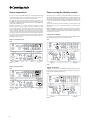
How to configure a basic system
lnbetriebnahme fiir Ungeduldige
Konfigurieren eines einfachen Systems
D8marrage rapide
Comment configurer un systeme simple
Guia rclpida
Como configurar un sistema basico
Avvio rapido
Come configurare il sistema di base
Snel starten
Hoe u een basis systeem configureert
Kom hurtigt i gang
Sadan konfigureres et almindeligt system
DbtCTpa~ ycTaHOBKa
KaK CKOHtPHrypHpOB3Tb OCHOBHYIO KaHaflbHYIO CHCTeMy
8 Cambridge Audio
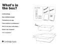
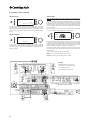
Wh at's in
the box ?
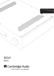
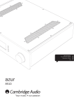
azur 851E
0
ooo
ooo
000
000
0
Lieferum fang
000
0 0
Que contient Ia boite?
::~ ~~~
Contenid o de Ia caja
Cosa contiene Ia confezio ne?
Wat u in de doos zult vinden •••
Hvad er der i kassen?
4TO B KOp06Ke ?
8
Cambridge Audio
=
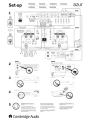
Set-up
Einrichtung
lnstalacion
Conflgureren
Installation
lmpostazloni
Opsatning
HacTpolliKa
azur
851E
1
~ ~~
[ ___0 ,_, ]
ii.\ii•OViifli..i400ii111'w;,
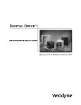
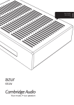
Input Type
Bal~ced
~
-
~
·® ® ® ® ® ®'
·® ® ® ® ® ®·
Ur:buid"CCd
851W
or l oder l ol
of 1 eller 1 ~n~
®
lnputType
!Jalanced
~
Unbalanced
851C
2
851E
851W
Pre-Amplifer
Class XD power amplifier
3
4
5
To get the best performance from your Azur
information.
No deje de leer el manual. Contiene toda Ia
informaciOn necesaria para obtener el maximo
rendlmiento de su equipo Azur 851E,I851W.
Um den vollen Leistungsumfang lhres Azur
851E/851W erschlieBen zu kOnnen, lesen Sie bitte
die weiterfUhrenden lnformationen im Handbuch.
Per ottenere le migliori prestazioni dal dispositive
Azur 851E/851W, leggere attentamente il manuale
perle relative informazion i.
851Ej851W please read the manual for more
Lres manualen for at fa flere oplysninger om,
hvordan du filr det bedste og meste ud af din Azur
851E/851W-enhed.
4T06bl OOOy-iiiiTb H81110Y'iWI'Ie xapaKTepHCTHKM OT
Bawero Azur 851E/851W np111 aKCnnyara411H,
nolKanyl::icTa, 03HaKOMbTeco c ,QanbHeHwel1
11H¢lOpM81..111eH B pyKOBO,QCTBe.
Pour profiter des meilleures performances de votre
Azur 851E/851W, veuillez consulter le manuel pour
obtenir des informations.
8 Cambridge Audio
Om de beste prestatles van uw Azur 851E/851W te
krijgen dient u de handleiding te lezen voor meer
informatie.
For further information about Cambridge Audio, our products, news, reviews and
support, please visit:
Weitere lnfos zu Cambridge Audio, unsere Produkte, Neuigkeiten, Testberichte und
Kundendienst finden Sie unter:
Pour obtenir des informations supplementaires sur Cambridge Audio, nos produits,
nouveautes, actualites et assistance, veuillez vous rendre sur notre site :
Para obtener mas informacion acerca de Cambridge Audio, nuestros productos,
noticias, resenas y so porte, visite:
Per maggiori informazioni su Cambridge Audio e i nostri prodotti, per notizie, articoli
e assistenza, visitare:
Voor meer informatie over Cambridge Audio, onze producten, nieuws, beoordelingen
en support (ondersteuning), kunt u onze website bezoeken:
Du kan finde flere oplysninger om Cambridge Audio, vores produkter, nyheder og
support pa:
6onee noAp06Hyto ~H¢opMa4lllK> o KOMnaHllll-1 Cambridge Audio, ee npoAyKTax,
063opax ll1 TeXHll14eCKO~ noAQep>KKe CM. Ha Be6-ca~Te:
HOBOCT~X,
('t')
&
N
www.cambridge-audio.com
N
'('t')
"""'
a.
<
2
azur
851E
Your music + our passion
ENGLISH
3UH$PSOLÀHU
User's manual
Contents
Important safety instructions .....................................................................3
Limited warranty..........................................................................................4
Rear panel connections ..............................................................................5
Front panel controls ....................................................................................6
Remote control ............................................................................................7
Source connections ....................................................................................8
Power syncing (On/Standby control)..........................................................8
Output connections - Balanced ..................................................................9
Output connections - Unbalanced .............................................................9
Mono Bridged connections...................................................................... 10
Operating instructions ............................................................................. 11
3UHDPSOLÀHUVHWXS ................................................................................... 11
CAP5: Five-way protection system........................................................... 14
Custom installation (C.I.) use .................................................................. 15
7HFKQLFDOVSHFLÀFDWLRQV ........................................................................... 15
Troubleshooting ........................................................................................ 15
Make sure you register your purchase.
Visit: www.cambridge-audio.com/sts
%\UHJLVWHULQJ\RX
OOEHWKHÀUVWWR
know about:
y Future product releases
y Software upgrades
y News, events and exclusive offers
plus competitions!
This guide is designed to make installing and using this
product as easy as possible. Information in this document has
been carefully checked for accuracy at the time of printing;
however, Cambridge Audio's policy is one of continuous
LPSURYHPHQW WKHUHIRUH GHVLJQ DQG VSHFLÀFDWLRQV DUH
subject to change without prior notice.
This document contains proprietary information protected
by copyright. All rights are reserved. No part of this manual
may be reproduced by any mechanical, electronic or other
means, in any form, without prior written permission of the
manufacturer. All trademarks and registered trademarks are
the property of their respective owners.
© Copyright Cambridge Audio Ltd 2013.
Cambridge Audio and the Cambridge Audio logo are
trademarks of Cambridge Audio.
Other brands mentioned are trademarks of their respective
owners and are used for reference purposes only.
2
azur
851E
ENGLISH
Important safety instructions
For your own safety please read the following important safety
instructions carefully before attempting to connect this unit to the mains
power supply. They will also enable you to get the best performance from
and prolong the life of the unit:
1. Read these instructions.
2. Keep these instructions.
3. Heed all warnings.
4. Follow all instructions.
5. Do not use this apparatus near water.
6. Clean only with a dry cloth.
7. Do not block any ventilation openings. Install in accordance with the
manufacturer's instructions.
8. Do not install near any heat sources such as radiators, heat registers,
VWRYHVRURWKHUDSSDUDWXVLQFOXGLQJRWKHUDPSOLÀHUVWKDWSURGXFH
heat.
9. Do not defeat the safety purpose of the polarized or grounding-type
plug. A polarized plug has two blades with one wider than the other.
A grounding-type plug has two blades and a third grounding prong.
The wide blade or the third prong are provided for your safety. If the
SURYLGHGSOXJGRHVQRWÀWLQWR\RXURXWOHWFRQVXOWDQHOHFWULFLDQIRU
replacement of the obsolete outlet.
10. Protect the power cord from being walked on or pinched, particularly
at plugs, convenience receptacles and the point where they exit from
the apparatus.
2QO\XVHDWWDFKPHQWVDFFHVVRULHVVSHFLÀHGE\WKHPDQXIDFWXUHU
12. Use with only the cart, stand, tripod, bracket, or
WDEOH VSHFLÀHG E\ WKH PDQXIDFWXUHU RU VROG ZLWK WKH
apparatus. When a cart is used, use caution when
moving the cart/ apparatus combination to avoid injury
from tip-over.
13. Unplug this apparatus during lightning storms or when unused for
long periods of time.
5HIHU DOO VHUYLFLQJ WR TXDOLÀHG VHUYLFH SHUVRQQHO 6HUYLFLQJ LV
required when the apparatus has been damaged in any way, such
as the power-supply cord or plug having been damaged, liquid has
been spilled or objects have fallen into the apparatus, the apparatus
has been exposed to rain or moisture, does not operate normally, or
has been dropped.
WARNING
²7RUHGXFHWKHULVNRIÀUHRUHOHFWULFVKRFNGRQRWH[SRVHWKLVXQLWWR
rain or moisture.
– Batteries (battery pack or batteries installed) shall not be exposed to
H[FHVVLYHKHDWVXFKDVVXQVKLQHÀUHRUWKHOLNH
The unit is of Class 1 construction and must be connected to a mains
socket outlet with a protective earthing connection.
The unit must be installed in a manner that makes disconnection of
the mains plug from the mains socket outlet (or appliance connector
from the rear of the unit) possible. Where the mains plug is used as the
disconnect device, the disconnect device shall remain readily operable.
Only use the mains cord supplied with this unit.
Please ensure there is ample ventilation. We recommend that you do
not place the unit in an enclosed space; if you wish to place the unit on
a shelf, use the top shelf to allow maximum ventilation. Do not put any
objects on top of this unit. Do not situate it on a rug or other soft surface
and do not obstruct any air inlets or outlet grilles. Do not cover the
ventilation grilles with items such as newspapers, tablecloths, curtains,
etc.
This unit must not be used near water or exposed to dripping or splashing
ZDWHURURWKHUOLTXLGV1RREMHFWVÀOOHGZLWKOLTXLGVXFKDVYDVHVVKDOO
be placed on the unit.
7KH OLJKWQLQJ ÁDVK ZLWK WKH DUURZKHDG V\PERO ZLWKLQ DQ HTXLODWHUDO
triangle is intended to alert the user to the presence of un-insulated
'dangerous voltage' within the product's enclosure that may be of
VXIÀFLHQWPDJQLWXGHWRFRQVWLWXWHDULVNRIHOHFWULFVKRFNWRSHUVRQV
The exclamation point within an equilateral triangle is intended to alert
the user to the presence of important operating and maintenance
instructions in the service literature relevant to this appliance.
WEEE symbol
The crossed-out wheeled bin is the European Union symbol
for indicating separate collection for electrical and electronic
equipment. This product contains electrical and electronic
equipment which should be reused, recycled or recovered
and should not be disposed of with unsorted regular waste.
Please return the unit or contact the authorised dealer from whom you
purchased this product for more information.
CE mark
This product complies with European Low Voltage (2006/95/
EC), Electromagnetic Compatibility (2004/108/EC) and
Environmentally-friendly design of Energy-related Products (2009/125/
EC) Directives when used and installed according to this instruction
manual. For continued compliance only Cambridge Audio accessories
should be used with this product and servicing must be referred to
TXDOLÀHGVHUYLFHSHUVRQQHO
C-Tick mark
This product meets the Australian Communications
Authority's Radio communications and EMC requirements.
Gost-R Mark
This product meets Russian electronic safety approvals.
FCC regulations
NOTE: THE MANUFACTURER IS NOT RESPONSIBLE FOR ANY RADIO
OR TV INTERFERENCE CAUSED BY UNAUTHORIZED MODIFICATIONS
TO THIS EQUIPMENT. SUCH MODIFICATIONS COULD VOID THE USER
AUTHORITY TO OPERATE THE EQUIPMENT.
This equipment has been tested and found to comply with the
limits for a Class B digital device, pursuant to Part 15 of the
FCC Rules. These limits are designed to provide reasonable
protection against harmful interference in a residential installation. This
equipment generates, uses and can radiate radio frequency energy
and, if not installed and used in accordance with the instructions, may
cause harmful interference to radio communications. However, there is
no guarantee that interference will not occur in a particular installation.
If this equipment does cause harmful interference to radio or television
reception, which can be determined by turning the equipment off and
on, the user is encouraged to try to correct the interference by one or
more of the following measures:
- Re-orient or relocate the receiving antenna.
- Increase the separation between the equipment and receiver.
- Connect the equipment into an outlet on a circuit different from that to
which the receiver is connected.
- Consult the dealer or an experienced radio/TV technician for help.
3
Limited warranty
Ventilation
IMPORTANT – The unit will become hot when in use. Do not stack
multiple units on top of each other. Do not place in an enclosed area
VXFKDVDERRNFDVHRULQDFDELQHWZLWKRXWVXIÀFLHQWYHQWLODWLRQ
Ensure that small objects do not fall through any ventilation grille. If this
happens, switch off immediately, disconnect from the mains supply and
contact your dealer for advice.
Positioning
Choose the installation location carefully. Avoid placing it in direct
VXQOLJKW RU FORVH WR D VRXUFH RI KHDW 1R QDNHG ÁDPH VRXUFHV VXFK
as lighted candles, should be placed on the unit. Also avoid locations
subject to vibration and excessive dust, cold or moisture. The unit can
be used in a moderate climate.
This unit must be installed on a sturdy, level surface. Do not place in a
sealed area such as a bookcase or in a cabinet. Do not place the unit on
an unstable surface or shelf. The unit may fall, causing serious injury to
a child or adult as well as serious damage to the product. Do not place
other equipment on top of the unit.
'XHWRVWUD\PDJQHWLFÀHOGVWXUQWDEOHVRU&5779VVKRXOGQRWEHORFDWHG
nearby due to possible interference.
Electronic audio components have a running in period of around a week
(if used several hours per day). This will allow the new components to
settle down and the sonic properties will improve over this time.
Power sources
The unit should be operated only from the type of power source indicated
on the marking label. If you are not sure of the type of power-supply to
your home, consult your product dealer or local power company.
This unit can be left in Standby mode when not in use and will draw
<0.5W in this state. To turn the unit off, switch off at the rear panel. If
you do not intend to use this unit for a long period of time, unplug it from
the mains socket.
Overloading
Do not overload wall outlets or extension cords as this can result in a risk
RIÀUHRUHOHFWULFVKRFN2YHUORDGHG$&RXWOHWVH[WHQVLRQFRUGVIUD\HG
power cords, damaged or cracked wire insulation and broken plugs are
GDQJHURXV7KH\PD\UHVXOWLQDVKRFNRUÀUHKD]DUG
Be sure to insert each power cord securely. To prevent hum and noise,
do not bundle the interconnect leads with the power cord or speaker
leads.
Cleaning
To clean the unit, wipe its case with a dry, lint-free cloth. Do not use any
FOHDQLQJÁXLGVFRQWDLQLQJDOFRKRODPPRQLDRUDEUDVLYHV'RQRWVSUD\
an aerosol at or near the unit.
Battery disposal
Batteries may contain substances harmful to the environment. Please
dispose of any discharged batteries with due consideration and in
accordance with local environmental/electronic recycling guidelines.
Servicing
These units are not user serviceable. Never attempt to repair,
disassemble or reconstruct the unit if there seems to be a problem.
A serious electric shock could result if this precautionary measure is
ignored. In the event of a problem or failure, please contact your dealer.
Cambridge Audio warrants this product to be free from defects in
materials and workmanship (subject to the terms set forth below).
Cambridge Audio will repair or replace (at Cambridge Audio's option) this
product or any defective parts in this product. Warranty periods may vary
from country to country. If in doubt consult your dealer and ensure that
you retain proof of purchase.
To obtain warranty service, please contact the Cambridge Audio
authorised dealer from which you purchased this product. If your dealer
is not equipped to perform the repair of your Cambridge Audio product,
it can be returned by your dealer to Cambridge Audio or an authorised
Cambridge Audio service agent. You will need to ship this product in
either its original packaging or packaging affording an equal degree of
protection.
Proof of purchase in the form of a bill of sale or receipted invoice, which
is evidence that this product is within the warranty period, must be
presented to obtain warranty service.
This Warranty is invalid if (a) the factory-applied serial number has
been altered or removed from this product or (b) this product was not
purchased from a Cambridge Audio authorised dealer. You may call
Cambridge Audio or your local country Cambridge Audio distributor to
FRQÀUPWKDW\RXKDYHDQXQDOWHUHGVHULDOQXPEHUDQGRU\RXPDGHD
purchase from a Cambridge Audio authorised dealer.
This Warranty does not cover cosmetic damage or damage due to
acts of God, accident, misuse, abuse, negligence, commercial use, or
PRGLÀFDWLRQ RI RUWR DQ\ SDUW RI WKHSURGXFW7KLV :DUUDQW\GRHVQRW
cover damage due to improper operation, maintenance or installation, or
attempted repair by anyone other than Cambridge Audio or a Cambridge
Audio dealer, or authorised service agent which is authorised to do
Cambridge Audio warranty work. Any unauthorised repairs will void this
Warranty. This Warranty does not cover products sold AS IS or WITH ALL
FAULTS.
REPAIRS OR REPLACEMENTS AS PROVIDED UNDER THIS WARRANTY
ARE THE EXCLUSIVE REMEDY OF THE CONSUMER. CAMBRIDGE AUDIO
SHALL NOT BE LIABLE FOR ANY INCIDENTAL OR CONSEQUENTIAL
DAMAGES FOR BREACH OF ANY EXPRESS OR IMPLIED WARRANTY IN
THIS PRODUCT. EXCEPT TO THE EXTENT PROHIBITED BY LAW, THIS
WARRANTY IS EXCLUSIVE AND IN LIEU OF ALL OTHER EXPRESS AND
IMPLIED WARRANTIES WHATSOEVER INCLUDING, BUT NOT LIMITED TO,
THE WARRANTY OF MERCHANTABILITY AND FITNESS FOR A PRACTICAL
PURPOSE.
Some countries and US states do not allow the exclusion or limitation of
incidental or consequential damages or implied warranties so the above
H[FOXVLRQVPD\QRWDSSO\WR\RX7KLV:DUUDQW\JLYHV\RXVSHFLÀFOHJDO
rights, and you may have other statutory rights, which vary from state to
state or country to country.
For any service, in or out of warranty, please contact your dealer.
Plug Fitting Instructions (UK only)
7KHFRUGVXSSOLHGZLWKWKLVDSSOLDQFHLVIDFWRU\ÀWWHGZLWKD8.PDLQV
SOXJ ÀWWHG ZLWK D DPS IXVH LQVLGH ,I LW LV QHFHVVDU\ WR FKDQJH
the fuse, it is important that a 3-amp fuse is used. If the plug needs
to be changed because it is not suitable for your socket, or becomes
GDPDJHGLW VKRXOGEHFXWRIIDQGDQDSSURSULDWHSOXJÀWWHGIROORZLQJ
the wiring instructions below. The plug must then be disposed of safely,
as insertion into a mains socket is likely to cause an electrical hazard.
6KRXOGLWEHQHFHVVDU\WRÀWDSLQ%6PDLQVSOXJWRWKHSRZHUFRUGWKH
ZLUHVVKRXOGEHÀWWHGDVVKRZQLQWKLVGLDJUDP7KHFRORXUVRIWKHZLUHV
in the mains lead of this appliance may not correspond with the coloured
markings identifying the terminals in your plug. Connect them as follows:
The wire which is coloured BLUE must be
connected to the terminal which is marked
with the letter 'N' or coloured BLACK.
The wire which is coloured BROWN must
be connected to the terminal which is
marked with the letter 'L' or coloured RED.
The wire which is coloured GREEN/
YELLOW must be connected to the
terminal which is marked with the letter 'E'
or coloured GREEN.
If a standard 13-amp (BS 1363) plug is used, a 3-amp fuse must be
ÀWWHGRULIDQ\RWKHUW\SHRISOXJLVXVHGDDPSIXVHPXVWEHÀWWHG
either in the plug or adaptor, or on the distribution board.
4
azur
851E
Power
5
6
Source 3
Trigger Out
Source 2
ENGLISH
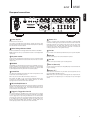
Rear panel connections
Source 1
GND
1
In
In
8
7
RS232C
Mains Voltage Selector Switch:
100-120V/220-240V AC~50/60Hz
2
Right
(Balanced)
Left
(Unbalanced)
Right
Left
(Balanced)
Pre Out
Right
(Unbalanced)
(Balanced)
Left
(Unbalanced)
Source 5
Source 4
Left
Right
GND
Rec Out
2
Out
Rec In
In
IR Emitter Trigger
Source 7
Control Bus
Source 6
4
Source 5
Off
Source 4
On
Designed and engineered in London, England
L
azur 851E Pre-Amplifier
L
1
13
Rated Power Consumption: 36W
www.cambridge-audio.com
R
R
Power AC
Right
(Balanced)
3
1
Power On/Off
Switches the unit on and off.
This product has APD (Auto Power Down) enabled as default. After
inactivity of 30 minutes, the product will automatically switch to Standby.
See later section for further details.
2
Mains Voltage Selector Switch
Switches the 851E mains voltage between 100-120V and 220-240V.
Note: Intended for use by a professional installer or Cambridge Audio
retailer only.
Left
(Unbalanced)
9
8
AC power socket
Once you have completed all connections to the unit, plug the AC power
cable into an appropriate mains socket then switch on. Your unit is now
ready for use.
4
RS232C
The RS232C port allows external serial control of the 851E, for use in a
custom installation. A full command set is available on the Cambridge
Audio website at www.cambridge-audio.com. This port can also be used
by Cambridge Audio service personnel for software updates.
Control Bus
In – Allows un-modulated commands from multi-room systems or other
components to be received by the unit.
Out – Loop out for Control Bus commands to another unit.
Also allows the 851E to turn on/off some Cambridge Audio units,
LQFOXGLQJ WKH PDWFKLQJ : SRZHU DPSOLÀHU 5HIHU WR WKH 3RZHU
syncing' section of this manual for more information.
6
Rec In
11
12
Source 7
Source 6
Source 1–3
9
Pre Out
)RUFRQQHFWLRQWRWKHEDODQFHGXQEDODQFHGLQSXWVRIDSRZHUDPSOLÀHU
Sub Out
Connect to the input on an active subwoofer if required.
11
Rec Out
Connect to the input sockets of your recording device.
12
Rec In (Source 8)
Connect to the output sockets of a Tape/MD player or other devices that
support recording.
13
5
Rec Out
10
Source 1–3 feature either unbalanced (phono/RCA) or balanced (XLR)
connections. Either type may be used but not both at the same time. The
balanced connection is the higher quality option and can reject noise
and interference in the cable when used with other equipment that
supports this function. An XLR connector is wired Pin 1 - Ground; Pin
2 - Hot (in-phase); Pin 3 - Cold (phase-inverted).
10
3
Sub Out
Source 4–7
These inputs are suitable for any 'line level' source equipment such as
CD players, DAB or FM/AM tuners etc.
Note: These inputs are for analogue audio signals only. They should not
be connected to the digital output of a CD player or any other digital
device.
IR (Infra-Red) Emitter In
Allows modulated IR commands from multi-room systems or IR repeater
systems to be received by the unit. Commands received here are not
looped out of the Control Bus. Refer to the 'Custom installation' section
of this manual for more information.
7
Trigger In, Trigger Out 1 and 2
For custom install use, the 851E can be turned on and off (i.e. brought
in and out of Standby mode) by the presence of 5-12V DC at the Trigger
input. A trigger input or by turning the 851E on from the remote/front
panel will also produce an internally generated 12V DC trigger output
at the Trigger Out 1 and 2 connection. This can be used to turn on/
6WDQGE\ D FRQQHFWHG : SRZHU DPSOLÀHU LI GHVLUHG 5HIHU WR WKH
'Power syncing' section of this manual for more information.
5
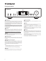
Front panel controls
azur 851E
Pre-Amplifier
7
10
1
Standby / On
Phones
Mode
1
2
3
Bass
4
5
Standby/On
Switches the unit between Standby mode (indicated by dim power LED)
and On (indicated by bright power LED). Standby is a low power mode
where the power consumption is less than 0.5 Watts. The unit can be
left in Standby mode when not in use. If the unit is not going to be used
for a long period of time it should be switched off via the Power On/Off
switch on the rear panel.
Note: As default the 851E ramps the volume up or down when switched
on and when going into Standby mode. This feature can be turned off if
GHVLUHGSOHDVHUHIHUWRWKH
3UHDPSOLÀHUVHWXS
VHFWLRQRIWKLVPDQXDO
for more information.
2
Phones
Allows for the connection of stereo headphones with a ¼" Jack plug.
Headphones with an impedance of between 32 and 600 ohms are
recommended. When the headphones are connected, the loudspeaker
relays are released switching off the output to the loudspeakers.
IMPORTANT! Do not use headphones that exceed a 3 meter cable.
3
Mode
Press to switch between Volume and Balance modes. Press and hold to
HQWHUWKH(6\VWHP&RQÀJXUHPHQX
4
Infrared sensor
Receives IR commands from the supplied Azur remote control. A clear
unobstructed line of sight between the remote control and the sensor
is required.
5
&
6
Source select buttons
Push the appropriate input selection button to select the source
component that you wish to listen to (highlighted by a solid circle on the
display). The signal selected is also fed to the Rec Out sockets so that it
may be recorded. The input should not be changed whilst recording (but
the recorded signal can be checked using the Rec input).
Note:
– Repeatedly pressing the Source 1, 2 or 3 buttons will toggle these
inputs between 'Balanced' and 'Unbalanced' source input.
²7KHVROLGFLUFOHZLOOÁDVKLIWKHUHDUHQRLQSXWVLJQDOVGHWHFWHG
7
Display
LCD used to control the 851E. Please refer to the 'Operating instructions'
DQG
3UHDPSOLÀHUVHWXS
VHFWLRQRIWKLVPDQXDOIRUPRUHLQIRUPDWLRQ
6
6
Treble
8
Direct
9
Volume
8
Bass and Treble
Press to release and rotate to allow subtle adjustments to the tonal
balance of the sound.
9
Direct
This control gives the audio signal a more direct path by bypassing the
tone control circuits for the purest possible sound quality.
The Bass/Treble icon (
) appears in the display when the bass
and treble circuit is active (in circuit) and is not present when they are
bypassed.
Note: Direct can be set on or off individually for each input. This setting
is recalled each time a source is selected.
10
Volume
Use to increase/decrease the level of the sound from the outputs of the
SUHDPSOLÀHU 7KLV FRQWURO DIIHFWV WKH OHYHO RI WKH ORXGVSHDNHU RXWSXW
the pre-amp output and the headphone output. It does not affect the
Rec Out connection.
7KH9ROXPHFRQWUROLVDOVRXVHGLQQDYLJDWLQJWKH(6\VWHP&RQÀJXUH
menus on the front panel display.
Please refer to the 'Operating instructions' section of this manual for
more information on some functions of these buttons.
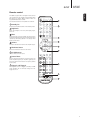
azur
851E
The 851E is supplied with a CA System remote control
WKDWRSHUDWHVERWKWKLVDPSOLÀHUDQG&DPEULGJH$XGLR
851 series and Stream Magic products. Insert the
supplied AAA batteries to activate.
7KHIXQFWLRQVUHOHYDQWWRWKHDPSOLÀHUDUHDVIROORZV
1
1
Standby/On
6ZLWFKHVWKHDPSOLÀHUEHWZHHQ2QDQG6WDQGE\PRGH
2
ENGLISH
Remote control
2
Brightness
Adjust the backlight of the front panel display; bright,
dim or off.
3
Mute
0XWHVWKHDXGLRRQWKHSUHDPSOLÀHU7KHPXWHPRGHLV
indicated by Mute appearing and the volume level being
UHSODFHG E\ WZR ÁDVKLQJ GDVKHV LQ WKH GLVSOD\ 3UHVV
again to cancel mute.
3
4
4
Volume
,QFUHDVHRUGHFUHDVHWKHYROXPHRIWKHDPSOLÀHURXWSXW
5
5
Illuminate button
Press to illuminate the buttons on the remote.
6
4
S1–S8 Sources
Used to select the source inputs.
7
Source Direct
Press to give the audio signal a more direct path to the
SRZHU DPSOLÀHU VWDJH RI \RXU DPSOLÀHU E\SDVVLQJ WKH
bass and treble control circuits for the purest possible
sound quality.
8
Trigger 1 and Trigger 2
6
Pressing either button to toggle on/standby a 851W
SRZHU DPSOLÀHU WKDW LV FRQQHFWHG WKURXJK WKH UHDU
Trigger Out 1 or 2.
7
8
7
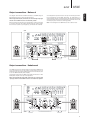
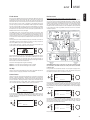
Source connections
Power syncing (On/Standby control)
Source 1, 2 and 3 on the 851E feature either unbalanced (phono/RCA)
or balanced (XLR) connections. The 851E is designed to work at its
highest performance when a balanced interconnect is used.
:KHQJRLQJLQRXWRI6WDQGE\PRGHWKH$]XU(SUHDPSOLÀHUFDQLI
desired) automatically control the 851W when connected via the Control
Bus sockets (the Control Bus sockets are colour-coded orange on the
rear panels of compatible Azur models). For this feature to work the units
must be connected together by RCA/phono leads. No futher setup is
necessary.
7KH GLDJUDPV EHORZ VKRZ WKH ( SUHDPSOLÀHU FRQQHFWHG WR DQ
Azur 851C CD player in unbalanced (Figure 1) and balanced (Figure 2)
FRQÀJXUDWLRQV7KH(FDQDOVREHFRQQHFWHGWRQRQ&DPEULGJH$XGLR
sources with balanced outputs.
Balanced connections in an audio system are designed to reject
electrical noise, from power wiring etc, and also the effects of noise
FXUUHQWV ÁRZLQJ WKURXJK JURXQG FRQQHFWLRQV 7KH EDVLF SULQFLSOH RI
balanced interconnection is to get the signal you want by subtraction,
using a three-wire connection. One signal wire (the hot or in-phase)
carries the normal signal, while other (the cold or phase-inverted) carries
an inverted version. The balanced input senses the difference between
the two lines to give the wanted signal. Any noise voltages that appear
identically on both lines (these are called common-mode signals) are
cancelled by the subtraction.
Figure 1: Unbalanced input
Connect the Control Bus Out from the 851E to the Control Bus In on the
851W. Continue the chain to other Azur models if it is required to sync
more units.
Note: The 851E features a Trigger Out which can alternatively be used to
control the 851W's Standby/On status if desired. Again, the procedure is
simply to connect the two units together (using a 3.5mm to 3.5mm mono
mini-jack lead in this case).
Control Bus connection
Control Bus is the recommended method when using an 851E and other
Cambridge Audio equipment with Control Bus In/Out.
851E
851E
Power
Source 3
Trigger Out
Source 2
Source 1
GND
1
On
Control Bus
Off
In
IR Emitter Trigger
Out
In
In
2
Left
(Balanced)
Right
(Unbalanced)
(Balanced)
Left
(Unbalanced)
Rec Out
Right
Rec In
(Unbalanced)
Source 7
Left
Pre Out
Source 6
(Balanced)
Source 5
Right
Rec Out
Rec In
Source 7
Source 6
Source 5
Source 4
Left
GND
Source 4
RS232C
Right
Designed and engineered in London, England
L
L
azur 851E Pre-Amplifier
Rated Power Consumption: 36W
www.cambridge-audio.com
R
R
Power AC
Right
(Balanced)
Left
(Unbalanced)
Sub Out
Phono/RCA
851C
851W
Figure 2: Balanced input
Trigger connection
851E
Power
Source 3
Trigger Out
Source 2
Source 1
GND
1
On
Control Bus
Off
In
IR Emitter Trigger
Out
In
In
Trigger In/Out can be useful if the 851W (and indeed 851E) is desired to
be controlled by other equipment that features trigger outputs (Custom
install and/or Multi-Room Systems etc).
2
Left
Right
(Unbalanced)
(Balanced)
Left
(Unbalanced)
Rec Out
(Balanced)
Rec In
Right
Source 7
(Unbalanced)
Source 6
Left
Pre Out
Source 5
(Balanced)
Source 4
Right
Rec Out
Rec In
Source 7
Source 6
Source 5
Source 4
851E
Left
Right
GND
Designed and engineered in London, England
L
azur 851E Pre-Amplifier
L
RS232C
Rated Power Consumption: 36W
www.cambridge-audio.com
R
R
Power AC
Right
(Balanced)
Left
(Unbalanced)
Sub Out
851C
851W
8
azur
851E
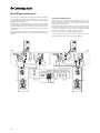
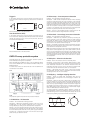
The diagram below shows the 851E connected to an 851W using the
Balanced Audio inputs via three-pin XLR connectors.
When using balanced (XLR) connections, the Left and Right Input Type
switches on the 851W must be in the 'Balanced' position.
Before making any connections to the loudspeakers, make sure all power
is turned off and only use suitable interconnects (e.g. banana plugs).
Ensure that the positive (+) and negative (-) connections are matched.
Your loudspeaker may have more than one pair of connecting terminals;
LF (Low Frequency) and HF (High Frequency). For single-wiring it is
recommended to connect to the LF terminals. The metal strip connecting
the low-frequency terminals to the high-frequency terminals must not be
removed (only to be removed for a bi-wiring system).
Note: ,QWKLVFRQÀJXUDWLRQWKH:PXVWEHVHWWR6WHUHRPRGH
851E
851W
Output connections - Unbalanced
The 851E features both balanced (XLR) and unbalanced (RCA/Phono)
output connections. For the best quality we recommend you use the
EDODQFHGRXWSXWZLWKSRZHUDPSOLÀHUVWKDWIHDWXUHWKLVFRQQHFWLRQVXFK
DVRXURZQ:&ODVV;'SRZHUDPSOLÀHU
7KHGLDJUDPEHORZVKRZVWKH(SUHDPSOLÀHUFRQQHFWHGWRDQ$]XU
:SRZHUDPSOLÀHUDQGDSDLURIORXGVSHDNHUV
When using unbalanced (phono/RCA) connections, the Left and Right
Input Type switches on the 851W must be in the 'Unbalanced' position.
851E
851W
9
ENGLISH
Output connections - Balanced
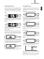
Mono Bridged connections
7KH PDWFKLQJ $]XU : SRZHU DPSOLÀHU IHDWXUHV 0RQR DQG %ULGJHG
Mono settings that allow two (or more) 851Ws to be used as monoblocks for high end systems. Below is an example using two 851Ws in
Bridged Mono with an 851E.
In Bridged Mono mode each 851W drives one speaker across its output
FKDQQHOVDFWLQJDVD:PRQRDPSOLÀHULQVWHDGRIDZSFVWHUHR
one. One 851W drives the left speaker and the other the right. See
the 851W manual for full details on Bridged Mono and other possible
combinations.
The example below uses balanced connections from 851E to each
851W, unbalanced connections can also be used and the principle is
the same.
851W
Important! 851W settings
Before making any connections to the loudspeakers, make sure all
power is turned off and only use suitable interconnects (e.g. banana
plugs). Ensure that the positive (+) and negative (-) connections are
wired as shown in the diagram.
When using balanced (XLR) connections, the Left and Right Input Type
switches on the 851W must be in the 'Balanced' position. When using
unbalanced (phono/RCA) connections, the Left and Right Input Type
switches on the 851W must be in the 'Unbalanced' position.
Only use the Left Inputs on the 851W for Bridged operation.
,QWKLVFRQÀJXUDWLRQWKH6WHUHR0RQRVZLWFKRQWKH:PXVWEHVHWWR
'Mono' and the Mono mode switch must be set to 'Bridged'.
Stereo
Stereo
Mono
Mono
Mono Mode
Mono Mode
Bi-Amp
Bi-Amp
Bridged
Bridged
Bridged
Bridged
Use Left Input for
Bridged / Bi-Amp
operation.
Use Left Input for
Bridged / Bi-Amp
operation.
851E
10
851W
851E
Operating instructions
3UHDPSOLÀHUVHWXS
The 851E has a custom-made display on the front of the unit that shows
the current status and allows you to access the 851E System settings
PHQX +HUH \RX FDQ DGMXVW WKH OLVWHQLQJ VHWWLQJV RI WKH DPSOLÀHU WR
personal preference. The menu system is easy to navigate and control,
simply by using the input select buttons to turn a feature on (solid circle)
or off (no circle) and the volume control knob to increase/decrease
settings.
The 851E features many advanced settings that allow its use to be
FXVWRPLVHGWRXVHUSUHIHUHQFH7KHLQSXWVFDQEHQDPHGWRUHÁHFWWKH
actual source units you have, each input can be trimmed so that each
sounds the same in terms of loudness when you switch between them
and other options.
Changing input names / source naming
Volume
Left
Right
Space
Mode
Default
Volume
Adjust the volume control knob on the front panel (or using the remote
control). The display will show the change in volume in decibels (dB).
'OdB' indicates maximum volume while lower volume settings progress
into the negative range. This can also be changed to arbitrary volume
units (0-90) in the System settings menu.
Save
Press and hold the relevant input select button for four seconds to
access the submenu. Press the Rename button, for example, if Input 1
is a CD player, name it "CD" etc. Letters are selected by turning the
volume control to scroll through the available characters. Press the Left
or Right button to select which character you wish to edit. Press the Save
button to save and exit the input name change menu.
System settings menu
Balance
Display
Sub LPF
Mode
Power
Mode
Vol Ramp
Control
Settings
PP Mute
Volume
Volume
Press the Mode button to enter Balance mode. 'Balance' will appear on
the display and can be adjusted using the volume control. Press the
Mode button again to return to Volume mode or wait 5 seconds for the
851E to automatically exit Balance mode.
Bass and Treble
Press and hold the Mode button to access the System settings menu.
The menu options are Display, Power, Control, Sub Low–Pass–Filter,
Volume ramp, and Phones Presence Mute.
To exit the System settings menu and its submenus, press the Mode
button again.
Display brightness
These controls allow subtle adjustments to the tonal balance of the
sound. Modify the sound through your loudspeakers and the Pre-Out
sockets only; they do not affect the signals sent through the Rec Out
connections. With a well produced CD and a good system the tone
controls are unnecessary and can be bypassed by pressing the Direct
button:
Enable
Vol dB
Mode
Bright
Display
Volume
Source 1
Source 5
Source 2
Source 6
Bass
Direct
In the System settings menu press the Display input select button to
enter the submenu. Press the relevant button for Enable/Disable,
Bright/Dim. Press the Mode button to exit the submenu.
Source 7
Source 3
Source 4
Treble
Direct
Sub LPF
Rec In
7KLVFRPSOHWHO\UHPRYHVWKHPIURPWKHVLJQDOSDWKIRUPD[LPXPÀGHOLW\
If the musical recording is of poor quality or other factors are affecting the
sound quality, if desired you can adjust the tone controls to compensate.
To use the tone controls press the Direct button so that the Bass/Treble
icon (b t) lights in the display indicating that they are active and direct
mode is Off. Now press the Bass or Treble control button to release them
DQGDOORZDGMXVWPHQWSXVKWKHPEDFNLQZKHQÀQLVKHG
Source 1
Source 5
Source 2
Source 6
Source 3
Source 7
Source 4
Rec In
Bass
Treble
Direct
Display
Sub LPF
Mode
Power
Vol Ramp
Control
Settings
PP Mute
Volume
The 851E features a Sub output that is a separate mono mix created
from the main pre-amp outputs. This output can have either a 'Flat' (i.e.
IXOOUDQJHXQÀOWHUHGIUHTXHQF\UHVSRQVHRUD+]/RZ3DVVÀOWHUFDQ
be applied. See frequency response graph below.
Full range
The 851E stores whether direct mode is on or off for each input
individually, for example it is possible to have the tone controls
automatically active for the Tuner source but not the CD source.
200Hz
Frequency
0RVW6XEZRRIHUVIHDWXUHEXLOWLQ/RZ3DVVÀOWHULQJDQG
)ODW
LVXVXDOO\
the best setting. This setting does not affect the main outputs which are
always full-range.
To select the 200Hz LPF, press the Sub LPF input select button in the
System settings menu. Press again to revert to the full range frequency
response. Press the Mode button to exit the System settings menu.
11
ENGLISH
azur
3UHDPSOLÀHUVHWXSFRQWLQXHG
Volume trim
Volume ramp
Display
Note: The Volume Trim menu item is hidden if the Fixed Volume is
enabled.
Sub LPF
Mode
Power
Vol Ramp
Control
Settings
PP Mute
Volume
The 851E automatically ramps the volume down when going into
Standby mode and up when coming out of Standby mode. To turn this
feature off, press the Vol Ramp input select button in the System settings
menu and set to off. Press the Mode button to exit the System settings
menu.
The relative levels of the inputs can be adjusted by gain trim. This allows
each to be adjusted so that each sounds the same in terms of average
loudness when you switch between them. Pick the loudest sounding
source and trim its level until it matches the average perceived level of
the others. Repeat this process if other sources also stand out as louder
than the average.
To set the input gain trim for each source, press and hold the required
input source button then select Vol Trim in the submenu:
Enable
Apply
Mode
Volume display
Minimum
Maximum
Enable
Vol dB
Current
Mode
Vol Trim
Save
Volume
Bright
Display
Volume
To change the volume display from decibels (-90 to 0dB) to arbitrary
volume units (0 to 90 units) select the Vol dB input button in the Display
submenu to turn off the volume in decibels. Press the Mode button to
exit the submenu.
Press the Enable button and use the volume control to set the gain
between 0 and -12 dB (the available range is restricted if the volume
is set very low). Press the Apply button to temporarily hear the new gain
settings, re-adjust the gain if necessary and press the Apply button
again. Press the Save button to save and exit the submenu.
Pressing the Current button will display the current volume value. This
is a useful function when setting new gain value and comparing it to the
current volume.
The other two settings sets the gain as following:
Minimum – Sets the minimum gain value to -1dB.
Maximum – Sets the maximum gain value to -12dB.
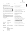
C
Example
R
L
851E/W used with an AV receiver
connected to Input 7 (which is then
set to fixed gain mode).
5.1 speaker connections shown.
851W
SW
851E
Stereo source e.g. 851C CD player
AV receiver
e.g. 651R
Surround sound source e.g. 752BD player
SL
12
SR
851E
Fixed volume
Devices menu
$Q\LQSXWRIWKH(LVDEOHWREHVHWIRUÀ[HGJDLQ:KHQHYHUWKLVLQSXW
is selected the gain will automatically go to this value and will not be
adjustable by the volume control. This can be useful with sources that
have their own built in volume control (such as some set-top boxes etc.)
Note: The Device menu item is hidden if the C-Bus is disabled.
Also, this feature can be used to integrate an AV Receiver which has
pre-amp outputs (such as our own 651R or 751R models) with the 851E.
The front Left and Right pre-amp outputs of the AV Receiver are simply
IHGWRDQ\GHVLUHGLQSXWRIWKH(DQGWKDWLQSXWVHWIRUÀ[HGJDLQ7KH
AV receiver is then wired to the various surround speakers whilst the
851E/W drives the Front Left and Right.
ENGLISH
azur
When going in/out of Standby mode the 851E can automatically turn
on and off other connected Cambridge Audio Azur models that have
control bus sockets. For this feature to work the units must be connected
together (see diagram) by RCA/phono leads. The Control Bus sockets
are colour-coded orange on the rear panels of any compatible Azur
models. Connect the Control Bus Out from the 851E to the Control Bus
In on another Azur model (e.g. 851W). Continue the chain to other Azur
models if required.
The 851E/W can then be used for Stereo sources as normal for best
sound quality. When it is desired to decode surround sound, select the
LQSXW FKRVHQ IRU À[HG JDLQ RQ WKH ( 1RZ WKH $9 5HFHLYHU FDQ EH
used to decode any of it’s surround sound sources. It will have control
of the volume of all channels and the 851E’s own volume control will be
disabled.
851C
<RXPD\ZLVKWRUHQDPHWKHÀ[HGOHYHOLQSXWDV´$9PRGHµRUVLPLODURQ
WKH($VWKHJDLQFDQEHÀ[HGWRDQ\YDOXHLWLVHDV\WRPDWFKWKH
level of the 851E to that of the other AV channels.
7R VHW D À[HG YROXPH IRU D VRXUFH SUHVV DQG KROG WKH UHTXLUHG LQSXW
source button then select Fixed Vol in the submenu:
Enable
Apply
Mode
Minimum
851W
Maximum
Fixed Vol
Save
Volume
3UHVVWKH(QDEOHEXWWRQDQGVHWWKHÀ[HGJDLQXVLQJWKHYROXPHFRQWURO
:KHQDVRXUFHKDVDÀ[HGLQSXWWKHEDODQFHLVDOZD\VVHWWRQHXWUDO
Press the Apply button to temporarily hear the new gain settings, readjust the gain if necessary and press the Apply button again. Press the
Save button to save and exit the submenu.
851E
The other two settings sets the gain as following:
Minimum²6HWVWKHPLQLPXPÀ[HGJDLQYDOXHWRG%
IMPORTANT! When doing a daisy-chain of other Azur models through
the Contol Bus, the 851E must be the main power source, otherwise
it will not work.
Maximum²6HWVWKHPD[LPXPÀ[HGJDLQYDOXHWRG%
Vol Clip
Used in conjunction with 851W via Control Bus. The 851E reduces the
YROXPHLIWKHUHLVDFOLSSLQJQRWLÀFDWLRQIURPWKH:
Control menu
Firstly, enable the Control Bus function. In the System settings menu,
press the Control input select button to enter the submenu then press
the C-Bus input select button to enable the function.
Front IR
Devices
Mode
Used in conjunction with Custom Installation (C.I.) systems or IR repeater
systems, it may be desirable to disable the IR function by setting IR to
off. In the System settings menu, press the Control input select button to
enter the submenu. Pressing the IR input select button will scroll through
the IR enabled options of Front, Back, Front + Back and IR IC (disable
front and back IR). Press the Mode button to exit the submenu.
Frn+Bck
Mode
C-Bus
C-Bus
RS232C
Control
Volume
Press the Devices input select button to enter the submenu. Select the
connected Azur models by pressing the appropriate input select button.
For example, CA xxxC for an Azur CD player (851C), CA xxxD for an Azur
DVD, CA xxxR for an Azur AV Receiver, SMx/xxxD for an Azur StreamMagic
and DACs etc.
RS232C
Control
Volume
Enable
CA XXXN
Mode
CA DAB T
CA 851C
In the System settings menu, press the Control input select button to
enter the submenu. Pressing the RS232C input select button will scroll
through the data bit rate options of 115200b, 38400b, 9600b, and
RS232C (disabled).
CA FM T
CA XXXD
CA XXXR
Devices
Volume
Pressing the Enable input select button to scroll through the options of
On+Off (turns all Azur units on and into Standby mode), Off (turns all
Azur units into Standby only), On (turns all Azur units on only), or Enable
(this disables the Control Bus function).
Front IR
Mode
C-Bus
115200b
On+Off
Control
Volume
CA XXXN
Mode
CA DAB T
CA 851C
CA FM T
CA XXXD
CA XXXR
Devices
Volume
Press the Mode button to exit the submenu.
13
Trigger In
2. W Overtemp – Over temperature detection
In the System settings menu, press the Power input select button to
enter the submenu. Press the Trig In input select button to enable the
function.
Indicator – Unit has switched off during operation.
Trig In
Mode
Auto PwD
Power
Volume
Description – CAP5 includes temperature detection which constantly
monitors the heat generated by the output transistors. If the monitored
temperature reaches a high level (suitably within the limits of the output
GHYLFHVWKHDPSOLÀHUZLOODXWRPDWLFDOO\VZLWFKLQWRDIDXOWPRGH,IWKH
ORXGVSHDNHULPSHGDQFHLVORZWKHWHPSHUDWXUHRIWKHDPSOLÀHUPD\ULVH
IDVWHUDVWKHDPSOLÀHULVZRUNLQJKDUGHU,IWKHDPSOLÀHULVPRXQWHGLQ
a cabinet or the ventilation slots are obstructed, the over-temperature
detection may activate/reactivate after a short listening time.
Press the Mode button to exit the submenu.
Remedy – The unit is not damaged, although it should be left for 15
minutes to cool down before being switched out of Standby.
Auto Power Down (APD)
3. W Overload – Overvoltage/overcurrent detection
In the System settings menu, press the Power input select button to
enter the submenu. Pressing the Auto PwD input select button will scroll
through the options of 2 hours, 1 hour, 30 mins, 15 mins, 10 mins, 5
mins and Auto PwD (disabled).
Indicator – Unit has switched off during operation.
Trig In
Description – CAP5 offers V/I protection by constantly monitoring the
output transistors to keep them working inside their Safe Operating
Area (SOA). The SOA is a set of limits given by the output transistor
PDQXIDFWXUHUWRHQVXUHUHOLDELOLW\9,DOVRSURWHFWVWKHDPSOLÀHUDJDLQVW
short-circuits on the speaker terminals during use.
Mode
Remedy²7KHDPSOLÀHULVEHLQJXVHGRXWVLGHLWVSHUIRUPDQFHHQYHORSH
Reduce the volume. Also check to see if there is a short- or partial shortcircuit between the loudspeaker terminals.
Auto PwD
Power
Volume
Press the Mode button to exit the submenu.
CAP5: Five-way protection system
Cambridge Audio has developed a proprietary protection system to
HQVXUHUHOLDELOLW\DQGORQJOLIHRILWVDPSOLÀHUV
When the 851E and the 851W are paired, if any, the 851E can detect
HUURUVIURPWKH:DQGDQHUURUQRWLÀFDWLRQZLOOÁDVKEULHÁ\RQWKH
851E LCD display.
To achieve this, connect the 'Control Bus Out' from the 851W to the
'Control Bus In' on the 851E.
851E
Note: If the indication remains the same and multiple loudspeakers are
being used on each loudspeaker output, then please remove a pair and
UHWU\,IWRRPDQ\ORXGVSHDNHUVDUHFRQQHFWHGWRDQ\DPSOLÀHUFDXVLQJ
WKHORDGUHVLVWDQFHWRGURSWRRORZWKHDPSOLÀHUZLOOEHRYHUGULYHQ&$3
will detect this situation. If the indication remains the same with only one
set of loudspeakers connected, there may be a fault with one or both of
the loudspeakers.
4. W Skp shrt – Short-circuit detection
Indicator – As the unit attempts to come out of Standby mode.
Description – During power up from Standby, CAP5 performs a check
on the loudspeaker terminals to see if a short across the terminals has
been accidentally introduced. If the resistance measured across the
loudspeaker terminals is too low, the unit will remain in Standby mode
until the fault has been removed and power up is re-attempted.
Remedy – User-related fault. There may be a short-circuit between
the loudspeaker terminals. Check all loudspeaker connections before
attempting to switch the unit out of Standby.
5. W Clipping – Intelligent clipping detection
Indicator – Volume is nudged down automatically. Note that this
automatic function will only work if the 'Vol Clipping' is enable in the
Input sub menu.
Description ² &$3 KDV WKH DELOLW\ WR GHWHFW ZKHQ WKH DPSOLÀHU VWDUWV
to clip or overdrive at its output, which can damage loudspeakers and
degrade the sound. Clipping distortion is caused at high volume levels
ZKHQWKHRXWSXWVLJQDOEULHÁ\JRHVRXWVLGHWKHPD[LPXPYROWDJHWKDW
WKH DPSOLÀHU FDQ SURYLGH FDXVLQJ WKH WRSV RI WKH VLJQDO WR ÁDWWHQ RII
When CAP5 detects clipping, the volume will be automatically nudged
down until CAP5 detects an undistorted output.
The clipping detection is disabled by default. However, to enable the
clipping detection, hold down the Standby/On button during power up
(whilst switching on the unit at the rear panel power switch). The unit will
LQGLFDWHWKLVE\ÁDVKLQJWKHSURWHFWLRQ/('IRUVHYHUDOVHFRQGV
851W
7KLVSURWHFWLRQV\VWHPFRPSULVHVÀYHPDLQSURWHFWLRQPHWKRGV
1. W DC Offset – DC detection
Indicator – Unit has switched off during operation.
Description – CAP5 offers loudspeaker protection if the output of the
DPSOLÀHU JRHV WR D KLJK FRQVWDQW YROWDJH '& 7KLV LV D UDUH IDXOW
although detecting it could just save those expensive loudspeakers.
Remedy – Due to the necessary sensitivity of the DC protection circuit,
KDUGFOLSSLQJRIWKHDPSOLÀHUPD\FDXVH'&SURWHFWLRQWREHWULJJHUHG
If this fault occurs please switch the unit off, power up again and check
operation with a reduced volume level. If the DC fault occurs again
please contact your dealer for service.
14
azur
851E
Troubleshooting
Control Bus
The 851E features a Control Bus input/output that IR Emitter
In
In
Out
allow un-modulated remote control commands
(positive logic, TTL level) to be received electrically
by the unit and looped to another unit if desired.
These control commands are typically generated
by custom installation (multi-room) systems or
remote IR receiver systems. The Control Bus sockets are colour-coded
orange.
There is no power
An IR Emitter Input is also provided that allows modulated IR remote
control commands to be received electrically by the unit. Commands on
this input operate the unit only and are not looped out demodulated on
the Control Bus Output.
There is no sound
An RS232C port is also featured which allows the 851E to be
controlled by C.I. systems.
Check that REC IN is not switched on (unless record input is required).
In addition the unit features 'direct' IR/Control codes as well as toggle
codes for some of their features to simplify programming custom
installation systems. Special direct On/Off and Mute commands can be
accessed on the supplied remote control for coding into C.I. systems as
follows:
3UHVV DQG KROG WKH 6WDQGE\2Q EXWWRQ 7KH UHPRWH ÀUVW JHQHUDWHV
its standby (toggle) command. Keep the button held down, after 12
VHFRQGVDQDPSOLÀHU2QFRPPDQGZLOOEHJHQHUDWHG,IWKHEXWWRQ
is kept held down for a further 12 seconds, an "Off" command is
generated.
3UHVVDQGKROGWKH0XWHEXWWRQ7KHUHPRWHÀUVWJHQHUDWHVLW
VPXWH
(toggle) command. Keep the button held down, after 12 seconds a
"Mute on" command will be generated. If the button is kept held down
for a further 12 seconds, a "Mute off" command is generated.
A full code table and RS232 protocol for this product is available on the
Cambridge Audio website:
www.cambridge-audio.com
ENGLISH
Custom installation (C.I.) use
Ensure the AC power cord is connected securely.
Ensure the plug is fully inserted into the wall socket and is switched on.
Check fuse in the mains plug or adaptor.
Make sure that the on/off switch at the back of the unit is turned on
Make sure the unit is not in Standby mode.
Check that source component is properly connected.
Check that your speakers are properly connected.
Make sure unit is not in mute mode.
If using Balanced connection ensure balanced input is selected,
indicated by a ring around the input indicator circle on the display
There is no sound on one channel
Ensure that balance control is in the correct position.
Check speaker connections.
Check interconnects.
There is a loud buzz or hum
Check turntable or tone arm for ground and connection lead fault.
Ensure no interconnects are loose or defective.
Ensure that your tape deck/turntable is not too close to the unit.
Unable to make or play tape recordings
Check that Record In and Record Out have been connected correctly.
7HFKQLFDOVSHFLÀFDWLRQV
There is weak bass or diffused stereo imaging
Ensure that speakers are not wired out of phase.
THD (+ noise)
< 0.00045% @1kHz
< 0.00057% @20kHz
S/N (unweighted)
< 110dBr
< 90dBu
Check that the batteries have not expired.
Frequency response
10Hz - 100kHz ± 0.1dB
Ensure IR receiver has not been disabled in system menu.
Crosstalk @1kHz
> 95dB
Input isolation
> 110dB
Maximum output
8V rms unbalanced
8V + 8V rms balanced
Output impedence
100 Ohms (Unbalanced or Balanced)
Subwoofer out
Flat or 200Hz 2nd Order Butterworth LPF
Max power consumption
36W
Bass & Treble controls
Shelving type
Max bass boost/cut ± 10 dB at 10 Hz
Max treble boost/cut ± 7.5 dB at 20 kHz
Dimensions (H x W x D)
115 x 430 x 385mm
(4.5 x 16.9 x 15.2")
Weight
8.1kg (17.9Lbs)
The remote handset will not function
Ensure that nothing is blocking the remote sensor.
For more frequently asked questions (FAQs), technical advice and
information on getting the most out of your 851E, please visit the
Support section on Cambridge Audio's website:
www.cambridgeaudio.com/support.php
For all servicing, in or out of warranty, please contact your dealer.
15
Cambridge Audio is a brand of Audio Partnership Plc
5HJLVWHUHG2IÀFH*DOOHU\&RXUW+DQNH\3ODFH
London SE1 4BB, United Kingdom
Registered in England No. 2953313
www.cambridge-audio.com
© 2013 Cambridge Audio Ltd
AP32333/1
''
''