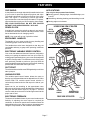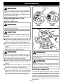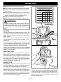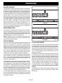
1
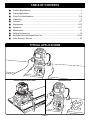
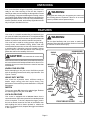
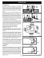
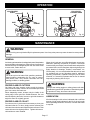
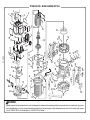
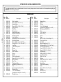
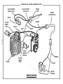
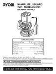
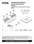
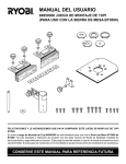
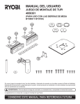
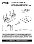
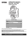
OPERATOR'S MANUAL
ROUTER - RE170VS
3
16
1 32
11 64
DOUBLE INSULATED
1
64
0
15 64
7 32
13
64
SPECIFICATIONS:
Depth Of Cut
Collet
Also Included With Packaging
Amperes
Peak Horsepower
Rating
No Load Speed
Net Weight
0 - 1-1/2 in. (0 - 38.1 mm)
1/2 in. (13 mm)
1/4 in. (6.4 mm)
8.5
1-3/4
120 Volts, 60 Hz, AC Only
15,000 - 25,000 RPM
3.92 kg. (8.625 lbs.)
THANK YOU FOR BUYING A RYOBI ROUTER.
Your new router has been engineered and manufactured to Ryobi's high standard for dependability, ease of operation, and
operator safety. Properly cared for, it will give you years of rugged, trouble-free performance.
CAUTION: Carefully read through this entire operator's manual before using your new router.
Pay close attention to the Rules for Safe Operation, Warnings, and Cautions. If you use your router properly and only for what
it is intended, you will enjoy years of safe, reliable service.
Thank you again for buying Ryobi tools.
SAVE THIS MANUAL FOR FUTURE REFERENCE
TABLE OF CONTENTS
■
Product Specifications ..................................................................................................... 1
■
Typical Applications ......................................................................................................... 2
■
Rules For Safe Operation .............................................................................................3-5
■
Unpacking ........................................................................................................................ 6
■
Features ........................................................................................................................6-7
■
Adjustments ................................................................................................................8-10
■
Operation ..................................................................................................................11-17
■
Maintenance .................................................................................................................. 17
■
Optional Accessories ..................................................................................................... 18
■
Exploded View and Repair Parts List ........................................................................20-21
■
Parts Ordering / Service ................................................................................................. 22
3
16
1 32
11 64
TYPICAL APPLICATIONS
1
64
0
15 64
7 32
13
64
ROUTING A GROOVE, WITH A GUIDE
3
64
3 3
13 64
7
5 32
18
1 32
9 64
11 64
4
16
11
6
3
16
FREEHAND ROUTING
1
64
0
Page 2
15 64
7 32
13
64
RULES FOR SAFE OPERATION
The purpose of safety symbols is to attract your attention to possible dangers. The safety symbols, and the
explanations with them, deserve your careful attention and understanding. The safety warnings do not by
themselves eliminate any danger. The instructions or warnings they give are not substitutes for proper accident
prevention measures.
SYMBOL
MEANING
SAFETY ALERT SYMBOL:
Indicates caution or warning. May be used in conjunction with other symbols or pictographs.
DANGER: Failure to obey a safety warning will result in serious injury to yourself or to others. Always
follow the safety precautions to reduce the risk of fire, electric shock and personal injury.
WARNING: Failure to obey a safety warning can result in serious injury to yourself or to others. Always
follow the safety precautions to reduce the risk of fire, electric shock and personal injury.
CAUTION: Failure to obey a safety warning may result in property damage or personal injury to yourself
or to others. Always follow the safety precautions to reduce the risk of fire, electric shock and personal
injury.
NOTE:
Advises you of information or instructions vital to the operation or maintenance of the equipment.
DOUBLE INSULATION
IMPORTANT
Double insulation is a concept in safety, in electric power
tools, which eliminates the need for the usual three-wire
grounded power cord. All exposed metal parts are isolated
from the internal metal motor components with protecting
insulation. Double insulated tools do not need to be grounded.
Servicing of a tool with double insulation requires extreme
care and knowledge of the system and should be performed
only by a qualified service technician. For service we suggest
you return the tool to your nearest RYOBI AUTHORIZED
SERVICE CENTER for repair. When servicing use only
identical Ryobi replacement parts.
WARNING:
WARNING:
The double insulated system is intended to protect the
user from shock resulting from a break in the tool's
internal wiring. Observe all normal safety precautions
related to avoiding electrical shock.
WARNING:
WEAR YOUR
SAFETY
GLASSES
FORESIGHT IS BETTER
THAN NO SIGHT
Do not attempt to operate this tool until you have read
thoroughly and understand completely all instructions,
safety rules, etc. contained in this manual. Failure to
comply can result in accidents involving fire, electric
shock, or serious personal injury. Save operator's manual
and review frequently for continuing safe operation, and
instructing others who may use this tool.
The operation of any router can result in foreign objects being thrown into your eyes,
which can result in severe eye damage. Before beginning power tool operation, always
wear safety goggles or safety glasses with side shields and a full face shield when
needed. We recommend Wide Vision Safety Mask for use over eyeglasses or standard
safety glasses with side shields.
Page 3
READ ALL INSTRUCTIONS
1.
2.
KNOW YOUR POWER TOOL. Read operator's
manual carefully. Learn its applications and
limitations as well as the specific potential
hazards related to this tool.
GUARD AGAINST ELECTRICAL SHOCK by
preventing body contact with grounded surfaces.
For example: Pipes, radiators, ranges,
refrigerator enclosures.
14.
DON'T ABUSE CORD. Never carry tool by cord
or yank it to disconnect from receptacle. Keep
cord from heat, oil and sharp edges.
15.
SECURE WORK. Use clamps or a vise to hold
work. It's safer than using your hand and it frees
both hands to operate tool.
16.
DON'T OVERREACH. Keep proper footing and
balance at all times. Do not use on a ladder or
unstable support.
17.
MAINTAIN TOOLS WITH CARE. Keep tools
sharp at all times, and clean for best and safest
performance. Follow instructions for lubricating
and changing accessories.
3.
KEEP GUARDS IN PLACE and in working order.
4.
KEEP WORK AREA CLEAN. Cluttered areas
and benches invite accidents.
5.
AVOID DANGEROUS ENVIRONMENT. Don't
use power tool in damp or wet locations or expose
to rain. Keep work area well lit.
18.
KEEP CHILDREN AND VISITORS AWAY. All
visitors should wear safety glasses and be kept
a safe distance from work area. Do not let
visitors contact tool or extension cord.
DISCONNECT TOOLS. When not in use, before
servicing, or when changing attachments, blades,
bits, cutters, etc., all tools should be disconnected
from power supply.
19.
REMOVE ADJUSTING KEYS AND
WRENCHES. Form habit of checking to see
that keys and adjusting wrenches are removed
from tool before turning it on.
20.
AVOID ACCIDENTAL STARTING. Don't carry
plugged-in tools with finger on switch. Be sure
switch is off when plugging in.
6.
7.
STORE IDLE TOOLS. When not in use tools
should be stored in a dry and high or locked-up
place - out of the reach of children.
8.
DON'T FORCE TOOL. It will do the job better
and safer at the rate for which it was designed.
9.
USE RIGHT TOOL. Don't force small tool or
attachment to do the job of a heavy duty tool.
Don't use tool for purpose not intended - for
example - A circular saw should never be used
for cutting tree limbs or logs.
10.
WEAR PROPER APPAREL. Do not wear loose
clothing or jewelry that can get caught in tool's
moving parts and cause personal injury. Rubber
gloves and nonskid footwear are recommended
when working outdoors. Wear protective hair
covering to contain long hair and keep it from
being drawn into nearby air vents.
21. MAKE SURE YOUR EXTENSION CORD IS IN
GOOD CONDITION. When using an extension
cord, be sure to use one heavy enough to carry
the current your product will draw. An undersized
cord will cause a drop in line voltage resulting in
loss of power and overheating. A wire gage size
(A.W.G.) of at least 14 is recommended for an
extension cord 50 feet or less in length. A cord
exceeding 50 feet is not recommended. If in
doubt, use the next heavier gage. The smaller the
gage number, the heavier the cord.
22.
OUTDOOR USE EXTENSION CORDS. When
tool is used outdoors, use only extension cords
suitable for use outdoors. Outdoor approved
cords are marked with the suffix W-A, for example
- SJTW-A or SJOW-A.
11.
ALWAYS WEAR SAFETY GLASSES. Everyday
eyeglasses have only impact-resistant lenses;
they are NOT safety glasses.
12.
PROTECT YOUR LUNGS. Wear a face or dust
mask if operation is dusty.
23.
KEEP CUTTERS CLEAN AND SHARP. Sharp
cutters minimize stalling and kickback.
13.
PROTECT YOUR HEARING. Wear hearing
protection during extended periods of operation.
24.
KEEP HANDS AWAY FROM CUTTING AREA.
Keep hands away from cutters. Do not reach
underneath work while cutter is rotating. Do not
attempt to remove material while cutter is rotating.
Page 4
RULES FOR SAFE OPERATION (Continued)
25.
NEVER USE IN AN EXPLOSIVE ATMOSPHERE. Normal sparking of the motor could
ignite fumes.
26.
INSPECT TOOL CORDS PERIODICALLY and
if damaged, have repaired at your nearest
AUTHORIZED SERVICE CENTER. Stay
constantly aware of cord location.
27.
INSPECT EXTENSION CORDS PERIODICALLY and replace if damaged.
28.
KEEP HANDLES DRY, CLEAN, AND FREE
FROM OIL AND GREASE. Always use a clean
cloth when cleaning. Never use brake fluids,
gasoline, petroleum-based products or any strong
solvents to clean your tool.
29.
STAY ALERT. Watch what you are doing and
use common sense. Do not operate tool when
you are tired. Do not rush.
30.
31.
CHECK DAMAGED PARTS. Before further use
of the tool, a guard or other part that is damaged
should be carefully checked to determine that it
will operate properly and perform its intended
function. Check for alignment of moving parts,
binding of moving parts, breakage of parts,
mounting, and any other conditions that may
affect its operation. A guard or other part that is
damaged should be properly repaired or replaced
by an authorized service center unless indicated
elsewhere in this instruction manual.
32.
INSPECT FOR and remove all nails from lumber
before routing.
33.
DRUGS, ALCOHOL, MEDICATION. Do not
operate tool while under the influence of drugs,
alcohol, or any medication.
34.
WHEN SERVICING, USE ONLY IDENTICAL
RYOBI REPLACEMENT PARTS.
35.
POLARIZED PLUGS. To reduce the risk of
electric shock, this tool has a polarized plug (one
blade is wider than the other). This plug will fit in
a polarized outlet only one way. If the plug does
not fit fully in the outlet, reverse the plug. If it still
does not fit, contact a qualified electrician to
install the proper outlet. Do not change the plug
in any way.
36.
DO NOT USE TOOL UNDER "BROWNOUT"
OR OTHER LOW VOLTAGE CONDITIONS.
Also, do not use with any device that could cause
the power supply voltage to change.
37.
WHEN USING THIS ROUTER WITH A ROUTER
TABLE, HELP PREVENT POSSIBLE SERIOUS
INJURY BY KEEPING THE CUTTER
GUARDED AT ALL TIMES. Use only UL listed
router tables, with guards, that have been
designed for use on routers that are of this type,
size, and weight.
38.
SAVE THESE INSTRUCTIONS. Review them
frequently and use them to instruct others who
may use this tool. If you loan someone this tool,
loan them these instructions also.
DO NOT USE TOOL IF SWITCH DOES NOT
TURN IT ON AND OFF. Have switches replaced
by an authorized service center.
WARNING: Some dust created by power sanding, sawing, grinding, drilling, and other construction activities
contains chemicals known to cause cancer, birth defects or other reproductive harm. Some examples of these
chemicals are:
• lead from lead-based paints,
• crystalline silica from bricks and cement and other masonry products, and
• arsenic and chromium from chemically treated lumber.
Your risk from these exposures varies, depending on how often you do this type of work. To reduce your
exposure to these chemicals: work in a well ventilated area, and work with approved safety equipment, such
as those dust masks that are specially designed to filter out microscopic particles.
Look for this symbol to point out important safety precautions.
It means attention!!! Your safety is involved.
SAVE THESE INSTRUCTIONS
Page 5
UNPACKING
Your router has been shipped completely assembled and
ready for use. After removing it from the box, inspect it
carefully to make sure no breakage or damage has occurred
during shipping. If any parts are damaged or missing, contact
your nearest Ryobi dealer to obtain replacement parts before
attempting to operate router. A 1/4 in. (6.4 mm) collet assembly,
wrench, operator's manual, and warranty registration are the
only loose parts included in the box.
WARNING:
If any parts are missing, do not operate your router until
the missing parts are replaced. Failure to do so could
result in possible serious personal injury.
FEATURES
Your router is a versatile woodworking tool which will give
you years of trouble-free performance. It is engineered with
the professional in mind, but its ease of operation allows the
amateur to produce work which is beautiful and precise.
Your router can be used for routing grooves, edge routing,
routing circles, and freehand routing. When used with
recommended accessories, such as a UL listed router table
or straight guide; it becomes even more versatile. Various
types of cutters, both with and without roller bearings as
guides also add to the versatility of this tool.
WARNING:
Do not allow familiarity with your router to make you
careless. Remember that a careless fraction of a second
is sufficient to inflict severe injury.
CAUTION: Use router bits for cutters only.
Also make sure all router bits and recommended accessories
are in accordance with listed specifications for this tool. For
example, do not use router bits that are rated at less than
25,000 RPM.
VARIABLE SPEED
CONTROL SELECTOR
SPINDLE
LOCK
INDICATOR
POINT(S)
3
16
1 32
Before attempting to use your router, familiarize yourself
with all operating features and safety requirements. See
Figures 1 and 2.
11 64
KNOW YOUR ROUTER
1
64
0
HEAVY DUTY MOTOR
Your router has a powerful motor, sufficient enough to
handle tough routing jobs that require heavy duty
performance. It has a 8.5 amp motor that delivers 1-3/4 peak
horsepower.
SWITCH
To turn your router ON, depress the switch trigger. Release
the switch trigger to turn your router OFF.
LOCK-ON FEATURE
Your router is equipped with a lock-on feature that is
convenient when continuous operation for extended periods
of time is required. To lock on, depress the trigger, push in
the lock-on button located on the side of the handle, then
while holding the lock-on button pushed in, release the
trigger. To release the lock, depress the trigger and release
it. See Figure 2.
Page 6
15 64
7 32
13
64
HANDLE
DEPTH
INDICATOR
RING(S)
CHIP
SHIELD
DEPTH
ADJUSTING
RING
FRONT VIEW OF ROUTER
POWER
HANDLE
Fig. 1
FEATURES
CHIP SHIELD
APPLICATIONS
A clear plastic see-through chip shield is installed on the front
of your router for protection against flying dust and chips.
The shield is designed to fit the front opening of the router
base. See Figure 1. If necessary to remove chip shield,
squeeze the tabs on each end and pull outward. To replace,
squeeze the tabs at each end, fit into opening, then release.
FOR YOUR PROTECTION, DO NOT USE ROUTER
WITHOUT CHIP SHIELD PROPERLY IN PLACE.
(Use only for the purposes listed below)
■ Routing grooves, shaping edges, freehand designs, etc.
in wood.
■ Chamfering, rabbeting, dadoing, and dovetailing in wood.
■ Routing edges on laminates.
DEPTH
INDICATOR
RING(S)
64
A spindle lock secures the spindle so that only one wrench
is needed to loosen the collet nut and change cutters. It also
leaves both hands free for changing cutters.
NOTE: Your router will not run if spindle is locked.
UPSIDE DOWN VIEW OF ROUTER
3
SPINDLE LOCK
7
32
1
15
ERGONOMIC HANDLES
64
0
32
4
1 6
3/8
The handles on your router provide for easy handling and
maintaining proper control when routing.
The handles have also been designed so that they are
comfortable and easy to grasp when operating in different
positions.
INDICATOR
POINT(S)
DEPTH
ADJUSTING RING
ELECTRONIC VARIABLE SPEED CONTROL
LOCK-ON
BUTTON
6
64
SOFT START
3 3
13 6
Your router has advanced electronic features, designed to
assist you in getting the maximum use from your router. By
making proper speed selections, your router can be adjusted
to specific routing needs. This eliminates much of the guess
work previously needed to perform a given job. Both the
experienced and inexperienced router users benefit, obtaining
professional like results with fewer job errors.
7
11
6
4
The soft start feature builds motor RPM gradually to minimize
start-up torque.
5 32
9 64
18
VARIABLE SPEED
The variable speed control feature allows the router to
develop a no load speed that can be adjusted from 15,000 to
25,000 RPM. The variable speed control selector is
conveniently located under the end cap on the side of your
router.
Speed can be set according to the approximate cutter
diameter you will be using and to the hardness of the material
being cut. See the chart in figure 10, on page 11. The best
cuts are made when the cutter is fed through material at the
proper rate of feed.
ELECTRONIC FEEDBACK
SWITCH
TRIGGER
CLAMPING
LEVER
POWER
HANDLE
SUBBASE WITH
STRAIGHT EDGE
REAR VIEW OF ROUTER
The electronic feedback feature of your router introduces the
flexibility of adjusting the motor speed to required job
conditions. An electronic speed control module senses the
load applied to the motor, and increases or decreases motor
voltage to compensate for and maintain desired RPM.
Page 7
Fig. 2
ADJUSTMENTS
SPINDLE LOCK
WARNING:
Your router should never be connected to power supply
when you are assembling parts, making adjustments,
installing or removing cutters, or when not in use.
Disconnecting your router will prevent accidental starting
that could cause serious injury.
1
INSTALLING/REMOVING CUTTERS
1
3
See Figures 3, 4, and 5.
3
2
2
■ UNPLUG YOUR ROUTER.
WARNING:
TO UNLOCK
SPINDLE
TO LOCK
SPINDLE
Failure to unplug your router could result in accidental
starting causing serious injury.
Fig. 3
CUTTER
WRENCH
COLLET
NUT
CAUTION:
To prevent damage to the spindle or spindle lock, always
allow motor to come to a complete stop before engaging
spindle lock.
TO LOOSEN
COLLET NUT
0
64
■ A spindle lock is located on the top of the end cap. See
Figure 3. To activate lock, (1) push spindle lock in, (2)
slide into lock position, then (3) release spindle lock.
■ Place your router upside down on table, then turn collet
nut with wrench until lock mechanism interlocks. See
Figure 4.
NOTE: Spindle lock is spring loaded and will snap into
position when lock mechanism interlocks.
15
64
7 3
2
TO TIGHTEN
COLLET NUT
WARNING:
Fig. 4
WARNING:
If you are changing a cutter immediately after use, be
careful not to touch the cutter or collet with your hands or
fingers. They will get burned because of the heat buildup
from cutting. Always use the wrench provided.
■ Remove cutters by turning collet nut counterclockwise
enough to allow cutter to slip easily from collet. See
Figure 4.
■ If installing cutter for the first time, it can be installed
once collet nut is loose. If changing cutters, cutter will
easily slip from collet after loosening collet nut.
■ The 1/2 in. (13 mm) collet is machined to precision
tolerances to fit cutters with 1/2 in. (13 mm) diameter
shanks. A 1/4 in. (6.4 mm) collet assembly has also
been provided with your router so that cutters with 1/4
in. (6.4 mm) shank bits can be used. See Figure 5.
Do not use cutters with undersized shanks. Undersized
shanks will not tighten properly and could be thrown from
tool causing injury.
WARNING:
Before connecting your router to power supply, always
check to be sure switch is not in lock-on position. Failure
to do so could result in accidental starting of your router
resulting in possible serious injury.
ELECTRICAL CONNECTION
Your router has a precision built electric motor. It should be
connected to a power supply that is 120 volts, 60 Hz, AC
only (normal household current). Do not operate this tool
on direct current (DC). A substantial voltage drop will cause
a loss of power and the motor will overheat. If your tool does
not operate when plugged into an outlet, double-check the
power supply.
Page 8
ADJUSTMENTS
INSTALLING/REMOVING CUTTERS
(Continued)
1/2 IN.
COLLET NUT
MOTOR SHAFT
■ To use cutters with 1/4 in. (6.4 mm) shank bits, the 1/2
in. (13 mm) collet assembly must be removed and replaced with the 1/4 in. (6.4 mm) collet assembly. Remove the 1/2 in. (13 mm) collet assembly by removing
collet nut, loosening collet screw securing collet to motor shaft, then removing collet assembly.
NOTE: The collet screw has left hand threads and you
will need a #2 phillips screwdriver to loosen collet screw.
Turn screw clockwise to loosen and counterclockwise to
tighten.
■ Replace with the 1/4 in. (6.4 mm) collet assembly,
securely tightening collet screw in collet to motor shaft,
then reassemble the 1/2 in. (13 mm) collet nut. See
Figure 5. Make sure collet can turn freely inside motor
shaft once collet screw is tight.
■ Insert shank of cutter into collet until shank bottoms out,
then pull it out 1/16 in. (1.6 mm) to allow for expansion
when the bit gets hot.
■ Tighten the collet nut securely by turning clockwise with
the wrench provided. See Figure 4.
WARNING:
1/2 IN. COLLET
ASSEMBLY
COLLET SCREW (LEFT HAND THREADS) USING A #2
PHILLIPS SCREWDRIVER, TURN SCREW CLOCKWISE
TO LOOSEN AND COUNTERCLOCKWISE TO TIGHTEN
1/4 IN.
COLLET ASSEMBLY
CUTTER WITH
1/4 IN. SHANK DIAMETER
Fig. 5
REAR VIEW OF ROUTER
CLAMPING
LEVER
TO
LOCK
If collet nut is not tightened securely, cutter may come out
during use causing serious personal injury.
■ Place spindle lock back in unlock position. Otherwise,
interlocking mechanism of spindle lock will not let you
turn your router on.
DEPTH OF CUT ADJUSTMENTS
LOC K
UN
LO CK
TO
UNLOCK
See Figures 6, 7, 8, and 9.
We recommend that cuts be made at a depth not exceeding
1/8 in. (3.2 mm) and that several passes be made to reach
depths of cut greater than 1/8 in. (3.2 mm).
DEPTH
INDICATOR
RING
■ UNPLUG YOUR ROUTER.
WARNING:
INDICATOR
POINT
1
64
0
15 64
7 32
13
64
DEPTH
ADJUSTING
RING
CUTTER
INSIDE SUBBASE
Page 9
3
16
1 32
■ Place your router on a flat surface, unlock clamping
lever, and turn depth adjusting ring until cutter is inside
subbase. See Figure 6.
■ Turn the depth adjusting ring until tip of cutter touches
flat surface (zero depth of cut). See Figure 7. Next turn
depth indicator ring until the zero lines up with the indicator point on front of motor housing. See Figure 6.
11 64
Failure to unplug your router could result in accidental
starting causing serious injury.
SUBBASE
Fig. 6
ADJUSTMENTS
3
16
1 32
■ Position your router so that the cutter can extend below
the subbase for desired depth setting. See Figure 8.
■ Turn the depth adjusting ring to obtain the desired depth
of cut. The distance the cutter moves can be read on the
depth adjusting ring. Each mark on the depth adjusting
ring indicates 1/64 inch (.4 mm) change in depth setting.
One indicator point is located on front of the motor
housing, the other one is located on the base.
■ Lock clamping lever, securing depth adjusting ring to
motor housing and base.
11 64
DEPTH OF CUT ADJUSTMENTS (Continued)
1
64
0
15 64
13
7 32
64
DEPTH OF CUT ADJUSTMENTS WHEN
ROUTER IS MOUNTED TO A ROUTER TABLE
CUTTER AT
ZERO DEPTH OF CUT
11 64
Fig. 7
3
VARIABLE SPEED CONTROL SELECTOR
16
1 32
See Figure 9.
The depth of cut is readable from both sides of the depth
adjusting ring. There is a depth indicator ring and indicator
point on both sides of the depth adjusting ring. The bottom
ring is convenient when using your router mounted to a
router table. The indicator point on the base should also be
used when using your router mounted to a router table.
The depth indicator rings are identical parts. Therefore,
when you have your router mounted upside down on a
router table, you set depth of cut by reading the scale
differently. Set the cutter at zero depth of cut, rotate depth
indicator ring to desired depth of cut on the scale, then turn
depth adjusting ring back to zero depth of cut and lock
clamping lever securely.
1
64
0
See Figure 10.
Your router has a variable speed control selector designed
to allow operator control of speed and torque limits. You
can make speed selections best suited to the type of cut,
the material being cut, and the size of bit being used. The
variable speed control selector allows you to adjust router
speed from 15,000 to 25,000 rpm. There is a six step scale
labeled A thru F on the variable speed control selector. To
increase the speed and torque of your router, turn the
variable speed control selector to a higher setting. Turn to a
lower setting to decrease speed and torque.
NOTE: If you do not want to use the variable speed control
selector, turn to the highest possible setting F.
The speed selection chart shown gives suggested speed
settings based on the diameter of the cutter and the type of
material being routed. See Figure 10.
13
7 32
15 64
64
CUTTER EXTENDED BELOW SUBBASE
Fig. 8
FOR ROUTER TABLE USE ONLY
PRACTICE BEFORE ACTUAL USE
11
3 6
4
13
64
Page 10
3 16
We suggest that you practice with the variable speed feature
of your router before installing a cutter and making cuts in
wood. Check the following before connecting your router
to power supply:
■ Make sure power supply is 120 volts, 60 Hz, AC only.
■ Make sure the spindle lock is in the unlocked position.
■ Make sure the trigger is not in the lock-on position.
7
BASE
INDICATOR
POINT
32
1
15
64
0
4
1 6
32
DEPTH
INDICATOR
RING
Fig. 9
OPERATION
■ Make sure there is not a cutter in the collet.
■ Make sure the collet does not extend below the subbase.
■ Choose the desired speed from the speed selection chart.
See Figure 10.
■ Turn the variable speed control selector to the desired
setting. Align desired setting on the variable speed control
selector with indicator mark on the lower end cap.
■ Plug your router into power supply source.
■ Grasp your router firmly with both hands and turn on.
SPEED SELECTION CHART
CUTTER SIZE
MATERIAL
1/2
3/4
E-F D-E A-B
A
MEDIUM
D-E C-D
A
A
HARD
C-D B-C
A
A
SOFT
WARNING:
3/8
1/4
VERY HARD D-E C-D C-D B-C
Always wear safety goggles or safety glasses with side
shields when operating your router. Failure to do so could
result in dust, shavings, loose particles or foreign objects
being thrown into your eyes, causing possible serious
injury.
VARIABLE SPEED
CONTROL SELECTOR
INDICATOR
MARK
ROUTING
LOWER
END
CAP
B
For ease of operation and maintaining proper control, your
router has two handles, one on each side of the router base.
When using your router hold it firmly with both hands as
shown in figure 11.
Before starting router, unplug it and make sure cutter is
securely tightened in collet nut and that depth of cut is
properly set.
Plug router into power supply, turn it on, and let motor build
to its full speed, then gradually plunge or feed cutter into
workpiece. DO NOT let the cutter contact workpiece before
turning on router and allowing it to develop full speed.
Remain alert and watch what you are doing. DO NOT
operate router when fatigued or under the influence of drugs,
alcohol, or any medication.
A
TO
DECREASE
SPEED
TO
INCREASE
SPEED
Fig. 10
3
16
1 32
When routing, the cutter rotates clockwise. Therefore, you
should feed the router into the workpiece from left to right.
When fed from left to right, the rotation of the cutter pulls the
router against the workpiece. If fed in the opposite direction,
the rotation forces of the spinning bit will tend to throw the
router away from the workpiece. This could cause loss of
control of your router. See Figure 15.
11 64
FEED DIRECTION
1
64
0
15 64
7 32
13
64
RATE OF FEED
IMPORTANT: The whole "secret" of professional routing
and edge shaping lies in making a careful setup for the cut
to be made and in selecting the proper rate of feed.
The proper rate of feed depends on several factors: the
hardness and moisture content of the wood, the depth of cut,
and the cutting diameter of the bit. When cutting shallow
grooves in soft woods such as pine, a faster rate of feed can
be used. When making deep cuts in hardwoods such as oak,
a slower rate of feed will be required.
Fig. 11
The best rate of feed is one that does not slow down the
router motor more than one-third of its no-load speed. If the
router is fed too fast, it will take large chips out of the wood
and leave gouge marks. If the router is fed too slow, it will
scorch or burn the wood.
Page 11
OPERATION
PROPER FEEDING
The right feed is neither too fast nor too slow. It is the rate at
which the bit is being advanced firmly and surely to produce
a continuous spiral of uniform chips — without hogging into
the wood to make large individual chips or, on the other hand,
to create only sawdust. If you are making a small diameter,
shallow groove in soft, dry wood, the proper feed may be
about as fast as you can travel your router along your guide
line. On the other hand, if the bit is a large one, the cut is deep
or the wood is hard to cut, the proper feed may be a very slow
one. Then, again, a cross-grain cut may require a slower
pace than an identical with grain cut in the same workpiece.
There is no fixed rule. You will learn by experience. . . by
listening to the router motor and by feeling the progress of
each cut. If at all possible, always test a cut on a scrap piece
of the workpiece wood, beforehand.
TOO FAST
SPEED SELECTION
In general, if the material being cut is hard, the cutter size is
large, or the depth of cut is deep - maximum 1/8 in. (3.2 mm),
then your router should be run at slower speeds. When these
situations exist, turn the variable speed control selector until
the desired speed is reached. See Figure 10.
NOTE: Carbide cutters cut at higher speeds than steel
cutters and should be used when cutting very hard materials.
Keep cutters sharp at all times.
TOO SLOW
Fig. 12
FORCE FEEDING
Clean, smooth routing and edge shaping can be done only
when the bit is revolving at a relatively high speed and is
taking very small bites to produce tiny, cleanly severed
chips. If your router is forced to move forward too fast, the
RPM of the bit becomes slower than normal in relation to its
forward movement. As a result, the bit must take bigger bites
as it revolves. “Bigger bites” mean bigger chips, and a
rougher finish. Bigger chips also require more power, which
could result in the router motor becoming overloaded.
Under extreme force-feeding conditions the relative RPM of
the bit can become so slow — and the bites it has to take so
large — that chips will be partially knocked off (rather than
fully cut off), with resulting splintering and gouging of the
workpiece. See Figure 12.
Your Ryobi router is an extremely high-speed tool (15,000 25,000 RPM no-load speed), and will make clean, smooth
cuts if allowed to run freely without the overload of a forced
(too fast) feed. Three things that cause “force feeding” are bit
size, depth-of-cut, and workpiece characteristics. The larger
the bit or the deeper the cut, the more slowly the router
should be advanced. If the wood is very hard, knotty, gummy
or damp, the operation must be slowed still more.
You can always detect “force feeding” by the sound of the
motor. Its high-pitched whine will sound lower and stronger
as it loses speed. Also, the strain of holding the tool will be
noticeably increased.
TOO SLOW FEEDING
It is also possible to spoil a cut by moving the router forward
too slowly. When it is advanced into the work too slowly, a
revolving bit does not dig into new wood fast enough to take
a bite; instead, it simply scrapes away sawdust-like particles.
Scraping produces heat, which can glaze, burn, or mar the
cut — in extreme cases, can even overheat the bit so as to
destroy its hardness.
In addition, it is more difficult to control a router when the bit
is scraping instead of cutting. With practically no load on the
motor the bit will be revolving at close to top RPM, and will
have a much greater than normal tendency to bounce off the
sides of the cut (especially, if the wood has a pronounced
grain with hard and soft areas). As a result, the cut produced
may have rippled, instead of straight sides. See Figure 12.
“Too-slow feeding” can also cause your router to take off in
a wrong direction from the intended line of cut. Always
grasp and hold your router firmly with both hands when
routing.
You can detect “too-slow feeding” by the runaway too-highly
pitched sound of the motor; or by feeling the “wiggle” of the
bit in the cut.
Page 12
OPERATION
DEPTH OF CUT
As previously mentioned, the depth of cut is important
because it affects the rate of feed which, in turn, affects the
quality of a cut (and, also, the possibility of damage to your
router motor and bit). A deep cut requires a slower feed than
a shallow one, and a too deep cut will cause you to slow the
feed so much that the bit is no longer cutting, it is scraping,
instead .
Making a deep cut is never advisable. The smaller bits —
especially those only 1/16 inch (1.6 mm) in diameter — are
easily broken off when subjected to too much side thrust. A
large enough bit may not be broken off, but if the cut is too
deep a rough cut will result — and it may be very difficult to
guide and control the bit as desired. For these reasons, we
recommend that you do not exceed 1/8 in. (3.2 mm) depth of
cut in a single pass, regardless of the bit size or the softness
or condition of the workpiece. See Figure 13.
To make deeper cuts it is therefore necessary to make as
many successive passes as required, lowering the bit 1/8 in.
(3.2 mm) for each new pass. In order to save time, do all the
cutting necessary at one depth setting, before lowering the
bit for the next pass. This will also assure a uniform depth
when the final pass is completed. See Figure 14.
DEPTH
OF CUT
WIDTH
OF CUT
Fig. 13
2ND.
PASS
2ND. PASS
1ST.
PASS
1ST. PASS
Fig. 14
ROUTER FEED
DIRECTION
ROUTING
Whenever you are routing a groove, your travel should be in
a direction that places whatever guide you are using at the
right-hand side. In short, when the guide is positioned as
shown in the first part of Figure 16, tool travel should be left
to right and counterclockwise around curves. When the
guide is positioned as shown in the second part of Figure 16,
tool travel should be right to left and clockwise around
curves. If there is a choice, the first setup is generally the
easiest to use. In either case, the sideways thrust you use is
against the guide.
Page 13
ROUTER FEED
DIRECTION
See Figures 15 and 16.
The router motor and bit revolve in a clockwise direction. This
gives the tool a slight tendency to twist (in your hands) in a
counterclockwise direction, especially when the motor is
starting up.
Because of the extremely high speed of bit rotation during a
“proper feeding” operation, there is very little kickback to
contend with under normal conditions. However, should the
bit strike a knot, hard grain, foreign object, etc. that would
affect the normal progress of the cutting action, there will be
a slight kickback—sufficient to spoil the trueness of your cut
if you are not prepared. Such a kickback is always in the
direction opposite to the direction of bit rotation.
To guard against such a kickback, plan your setup and
direction of feed so that you will always be thrusting the
tool—to hold it against whatever you are using to guide the
cut—in the same direction that the leading edge of the bit is
moving. In short, the thrust should be in a direction that keeps
the sharp edges of the bit continuously biting straight into
new (uncut) wood.
ROUT END
GRAINS FIRST
DIRECTION OF FEED AND THRUST
BIT
ROTATION
BIT
ROTATION
ROUTER FEED
DIRECTION
Fig. 15
GUIDE OUTSIDE
ROTATION
THRUST
FEED
GUIDE
GUIDE INSIDE
GUIDE
ROTATION
FEED
THRUST
Fig. 16
OPERATION
STARTING AND ENDING A CUT
INTERNAL ROUTING
ROUTER
Tilt router and place on workpiece, letting edge of subbase
contact workpiece first. Be careful not to let router bit contact
workpiece. Turn router on and let motor build to its full speed.
Gradually feed cutter into workpiece until subbase is level
with workpiece.
PILOT
WARNING:
WORK
Keep a firm grip on router with both hands at all times.
Failure to do so could result in loss of control leading to
possible serious injury.
TOP EDGE SHAPING
ROUTER
Upon completion of cut, turn motor off and let it come to a
complete stop before removing router from work surface.
WORK
WARNING:
Never pull router out of work and place upside down on
work surface before the cutter stops.
PILOT
EDGING WITH PILOT BITS
GUIDE
See Figure 17.
Rabbets and molded edges can be cut using piloted cutters.
The pilot extends below the cutter. Some pilots are solid
extensions of the cutter. Others are ball bearing guides that
are fastened to the end of the cutter. The pilots allow the
cutters to turn while the pilot follows the edge of the workpiece.
Arbor-type bits with pilots are excellent for quick, easy, edge
shaping. They will follow workpiece edges that are either
straight or curved. The pilot prevents the bit from making too
deep a cut; and holding the pilot firmly in contact with the
workpiece edge throughout prevents the cut from becoming
too shallow.
Whenever the workpiece thickness together with the desired
depth of cut (as adjusted by router depth setting) are such
that only the top part of the edge is to be shaped (leaving at
least a 1/16 inch (1.6 mm) thick uncut portion at bottom), the
pilot can ride against the uncut portion, which will serve to
guide it. See Figure 17. However, if the workpiece is too thin
or the bit set too low so that there will be no uncut edge to ride
the pilot against, an extra board to act as a guide must be
placed under the workpiece. This “guide” board must have
exactly the same contour — straight or curve — as the
workpiece edge. If it is positioned so that its edge is flush with
the workpiece edge, the bit will make a full cut (in as far as
the bit radius). On the other hand, if the guide is positioned
as shown in Figure 17 (out from the workpiece edge), the bit
will make less than a full cut — which will alter the shape of
the finished edge.
NOTE: If desired any of the piloted bits can be used without
a pilot for edge shaping with guides, as preceding. Also, the
size (diameter) of the pilot that is used determines the
maximum cut width that can be made with the pilot against
WHOLE EDGE SHAPING
6
Fig. 17
5
3
PROPER CUTTING SEQUENCE
4
2
1
7
8
1/4 in. TO 1 in.
Fig. 18
the workpiece edge (the small pilot exposes all of the bit; the
large one reduces this amount by 1/16 inch (1.6 mm).
When routing all the edges of a panel or board, rout the end
grain first. Any splintering that occurs at the corners will then
be removed when routing the edge. Start each side 1/4 in.
(6.4 mm) away from the end. Feed the cutter into the wood
until the pilot contacts the uncut edge. Then, slowly back the
router to shape the corner. Next, move the router forward to
shape the rest of the edge. Be careful to keep the pilot
pressed against the uncut edge. Repeat this procedure on
each side of the panel. Figure 18 shows the proper sequence
of cuts to make when edge routing four sides of a panel.
Page 14
OPERATION
EDGE ROUTING
Place router on workpiece, making sure the router bit does
not contact workpiece. Turn router on and let motor build to
its full speed. Begin your cut, gradually feeding cutter into
workpiece.
WARNING:
3 3
13 64
16
64
3
Keep a firm grip on router with both hands at all times.
Failure to do so could result in loss of control leading to
possible serious injury.
7
11
6
4
5 32
18
9 64
Upon completion of cut, turn motor off and let it come to a
complete stop before removing router from work surface.
WARNING:
Never pull router out of work and place upside down on
work surface before the cutter stops.
ROUTING WITH STRAIGHT EDGE OF SUBBASE
See Figure 19.
The subbase on your router has a straight edge. It should be
used when placing your router against an edge guide or
fence and routing grooves parallel to the fence.
ROUTING WITH STRAIGHT EDGE OF
SUBBASE AGAINST AN EDGE GUIDE
Fig. 19
ROUTING GROOVES
3 3
13 64
See Figure 20.
When routing across the face of boards, set router at desired
depth of cut, place the edge of router base against workpiece,
and turn on your router. Slowly feed the cutter into the
workpiece along desired line of cut.
WARNING:
64
3
16
7
11
6
4
5 32
9 64
18
If desired depth of cut is greater than can be safely cut in
one pass, make cuts in two or more passes.
When routing straight cuts across stock, clamp a straight
edge to the workpiece to use as a guide. Position the
straightedge parallel to the line of cut and offset the distance
between the cutting edge of the cutter and the edge of the
router base. Hold the router base against the straightedge
and rout the groove.
When routing a groove wider than the diameter of the cutter,
clamp a straightedge on both sides of the cutlines. Position
both guides parallel to the desired line of cut and spaced
equal distances from the desired edges of the groove. Rout
along one guide; then, reverse direction and rout along the
other guide. Clean out any remaining waste in the center of
the groove freehand.
Page 15
Fig. 20
OPERATION
FREEHAND ROUTING
3
1
64
0
When freehand routing, we suggest the following:
■ Draw or layout the pattern on workpiece.
■ Choose the appropriate cutter. NOTE: A core box or Vgroove bit is often used for routing letters and engraving
objects. Straight bits and ball mills are often used to
make relief carvings. Veining bits are used to carve
small, intricate details.
■ Rout the pattern in two or more passes. Make the first
pass at 25% of the desired depth of cut. This will provide
better control as well as being a guide for the next pass.
■ Do not rout deeper than 1/8 in. (3.2 mm) per pass or
cut.
15 64
7 32
13
64
FREEHAND ROUTING
WARNING:
Do not use large router bits for freehand routing. Use of
large router bits when freehand routing could cause loss
of control or create other hazardous conditions that could
cause possible serious personal injury.
16
1 32
There are two basic techniques for freehand routing:
■ Routing letters, grooves, and patterns into wood. See
Figure 21.
■ Routing out the background, leaving the letters or pattern
raised above the surface.
11 64
See Figure 21.
When used freehand, your router becomes a flexible and
versatile tool. This flexibility makes it possible to easily rout
signs, relief sculptures, etc.
Fig. 21
WARNING:
When using a UL listed router table, large router bits
should be used for edging only. Do not use router bits
that are larger in diameter than the opening in the router
base for any purpose. Failure to heed this warning could
result in serious personal injury.
WARNING:
Do not use with router tables that fail to conform to safe
woodworking practices and offer proper guarding for the
cutter. Failure to comply can result in an accident causing
possible serious injury.
ROUTER TABLE USE
See Figures 22 and 23.
■ Your Ryobi RE170VS router can be used on UL listed
router tables such as the Ryobi BT3000SXI Precision
Cutting System. It may be necessary to remove the
subbase to utilize the full pattern of some edge forming
bits such as Roman Ogee and round-over bits. Remove
the four (4) #10-32 pan head screws and subbase. With
the subbase base removed, the router is secured to the
mounting plate with 5/16-18 x 3/4 in., tapered flat head
screws provided in the Ryobi Router Mounting Kit model
number 4950300 or available at your local hardware
store.
WARNING:
ALWAYS make sure the shank of the router bit is seated
within 1/16 in. of the bottom of the collet. Extending the
shank of the router bit more than 1/16 in. beyond the
base of the collet could cause improper engagement of
the collet to the bit and result in serious personal injury.
Page 16
WARNING:
Use only 5/16-18 x 3/4 in. machine screws to mount the
router in an inverted position for table use. The use of
smaller screws, such as the #10-32 machine screws
provided for mounting the subbase, could provide an
insecure mounting and result in the risk of serious
personal injury.
OPERATION
#10-32 PAN HEAD
SCREW
5/16-18 X 3/4 IN.
FLATHEAD SCREW
BASE
BASE
SUBBASE
Fig. 23
Fig. 22
MAINTENANCE
WARNING:
When servicing use only identical Ryobi replacement parts. Use of any other parts may create a hazard or cause product
damage.
GENERAL
Avoid using solvents when cleaning plastic parts. Most plastics
are susceptible to damage from various types of commercial
solvents and may be damaged by their use. Use clean cloths
to remove dirt, carbon dust, etc.
WARNING:
Do not at any time let brake fluids, gasoline, petroleumbased products, penetrating oils, etc. come in contact
with plastic parts. They contain chemicals that can
damage, weaken, or destroy plastic.
When electric tools are use on fiberglass boats, sports cars,
wallboard, spackling compounds, or plaster, it has been
found that they are subject to accelerated wear and possible
premature failure, as the fiberglass chips and grindings are
highly abrasive to bearings, brushes, commutators, etc.
Consequently, it is not recommended that this tool be used
for extended work on any fiberglass material, wallboard,
spackling compounds, or plaster. During any use on these
materials, it is extremely important that the tool is cleaned
frequently by blowing with an air jet.
WARNING:
PROPER CARE OF CUTTERS
Get faster and more accurate cutting results by keeping
cutters clean and sharp. Remove all accumulated pitch and
gum from cutters after each use.
When sharpening cutters, sharpen only the inside of the
cutting edge. Never grind the outside diameter. Be sure
when sharpening the end of a cutter to grind the clearance
angle the same as originally ground.
PROPER CARE OF COLLET
From time to time, it also becomes necessary to clean your
collet and collet nut. To do so, simply remove collet nut from
collet and clean the dust and chips that have collected. Then
return collet nut to its original position. Tighten collet nut on
collet without a cutter installed.
Always wear safety goggles or safety glasses with side
shields during power tool operation or when blowing dust.
If operation is dusty, also wear a dust mask.
LUBRICATION
All of the bearings in this tool are lubricated with a sufficient
amount of high grade lubricant for the life of the unit under
normal operating conditions. Therefore, no further lubrication
is required.
Page 17
OPTIONAL ACCESSORIES
The following recommended accessories are current and were available at the time this manual was printed:
ITEM NO.
4070175
4070176
6090080
DESCRIPTION
Template Guide Adapter For Ryobi Template Guides
Template Guide Adapter For Porter Cable Rockwell and B&D Template Guides
Straight Guide For Ryobi Routers - Model Nos. R160, R165, RE 170, RE170VS, R175, RE175,
R180, and RE185
HELPFUL HINTS
✓
✓
✓
✓
✓
✓
✓
✓
✓
✓
✓
✓
Always clamp workpiece securely before routing.
A safe operator is one who thinks ahead.
Always wear eye protection when routing.
Make setup adjustments carefully. Then double check. Measure twice and cut once.
Keep cutters clean and properly sharpened.
Don’t let familiarity make you careless.
Study all safety rules and do the job safely.
NEVER place your hands in jeopardy.
Make certain clamps can’t loosen while in use.
Test difficult setups on scrap—Don’t waste lumber.
Plan each operation before you begin.
Clean your router frequently. This will provide smoother operation of depth adjusting ring and clamping lever areas.
Shake router or blow with an air jet to remove sawdust buildup.
✓ DO NOT ABUSE POWER TOOLS. Abusive practices can damage tool as well as workpiece.
✓ THINK SAFETY BY THINKING AHEAD.
Page 18
NOTES
Page 19
RYOBI ROUTER – MODEL NUMBER RE170VS
2
3
4
1
6
4
5
7
14
16 15
8 28
29
53
9
13
52
51
30
52
12
10
17
50
11
31
Page 20
31
18
15
34
35
32
19
33
33
22
48
49 58
57
59
46
42
26
26
47
55 56
50
41
15
27
39
40
23
25 24
49
38
21
20
36
37
54
44
43
25
43
61
45
63 62
61
61
62
63 60
64
WARNING:
Improper repair of a double insulated tool can result in damages to the double insulation system possibly causing electrical shock or electrocution. Any repairs
requiring disassembly of your tool requires safety testing and should only be performed by a Ryobi authorized service center. For the repair center nearest
you call 1-800-525-2579 in the United States or 1-800-265-6778 in Canada.
RYOBI ROUTER – MODEL NUMBER RE170VS
The model number will be found on a plate attached to the motor housing. Always mention the model number in all correspondence regarding your
ROUTER or when ordering repair parts.
PARTS LIST
Page 21
Key
No.
Part
Number
1
2
3
4
5
6
7
8
9
10
11
12
13
14
15
16
17
18
19
20
21
22
23
24
25
26
27
28
29
30
31
32
974323-001
999053-003
973671-001
989592-002
974799-001
982016-001
974289-001
974927-001
974617-001
974779-001
974800-001
990705-009
970771-001
616081-003
616081-014
974907-001
982261-001
975029-001
989573-001
973679-001
612855-001
968303-098
612858-002
714096-807
968304-026
611686-003
974959-002
968305-010
968307-141
968306-131
607896-001
974252-003
33
974096-001
Description
Quan.
Shaft Lock Label .................................................. 1
Screw (#5-10 x 1/2 in. Fil. Hd.) ............................ 1
Actuator Button .................................................... 1
Screw (#8-10 x 1-3/8 in. Fil. Hd.) ........................ 3
Upper End Cap .................................................... 1
Data Plate ............................................................ 1
Caution Label ...................................................... 1
Speed Control Label ............................................ 1
Speed Control Module ......................................... 1
Speed Control Dial .............................................. 1
Lower End Cap .................................................... 1
Screw (#8-22 x 5/8 in. Pan Hd. Hi-Lo) ................ 1
Dial Detent Ratchet ............................................. 1
Screw (#8-18 x 1 in. Pan Hd. T.C.) ..................... 1
Screw (#8-18 x 11/16 in. Pan Hd. T.C.) .............. 3
Logo Plate ........................................................... 1
Lower End Cap Label .......................................... 1
Bumper ................................................................ 4
Retainer Clip ........................................................ 1
Shaft Lock Lever .................................................. 1
Spring .................................................................. 2
Switch .................................................................. 1
Slide Lock Assembly ........................................... 1
Screw (#10-16 x 1 in. Fil. Hd. T.F.) ..................... 2
Brush Assembly ................................................... 2
Brush Tube .......................................................... 2
Top Bearing Plate ................................................ 1
Ball Bearing (NTN#608ZZ/1E) ............................ 1
Field ..................................................................... 1
Armature (Includes Key No. 28) .......................... 1
Retaining Ring ..................................................... 2
1/2 in. Collet Assembly
(Includes One of Key Nos. 31 and 33) ................ 1
Shoulder Screw ................................................... 2
Key
No.
Part
Number
34
35
36
37
617932-002
622347-018
969313-001
974252-005
38
39
40
41
42
43
968305-041
970105-024
973844-001
973657-002
973688-001
612556-003
44
45
46
47
48
49
50
51
52
53
54
55
56
57
58
59
60
61
62
63
982020-002
973672-001
974908-004
726676-002
974998-001
616968-003
610120-005
974239-002
974516-001
974098-001
973669-001
622347-020
970712-002
973689-001
623924-007
974997-001
968303-046
998586-001
973668-002
974518-001
972000-774
Description
Quan.
Retaining Ring ..................................................... 1
Washer ................................................................ 1
O Ring .................................................................. 2
1/4 in. Collet Assembly
(Includes One of Key Nos. 31 and 33) ................ 1
Ball Bearing (6004LLBCM) .................................. 1
Cord ..................................................................... 1
1/2 in. Collet Nut .................................................. 1
Motor Housing ..................................................... 1
Pointer ................................................................. 1
Screw
(#8-18 x 9/16 in. Flat Hd. Phillips T.C.) ............... 4
Power Handle Cord ............................................. 1
Chip Shield .......................................................... 1
Base (Includes Key No. 58) ................................. 1
Set Screw (#8-32 x 7/16 in. Flat Point) .............. 1
Auxiliary Handle Assembly .................................. 1
Screw (#6-20 x 5/8 in. Pan Hd. T.C.) .................. 2
Screw (#6-10 x 3/4 in. Pan Hd.) .......................... 8
Ring Assembly ..................................................... 1
Screw (#4-40 x 3/4 in. Pan Hd.) .......................... 2
Lower Bearing Plate ............................................ 1
Depth Lock Lever ................................................ 1
Washer ................................................................ 1
Screw (#10-32 x 5/16 in. Pan Hd.) ...................... 1
Lock Lever Label ................................................. 1
Needle Roller ....................................................... 1
Power Handle Assembly ..................................... 1
Switch .................................................................. 1
Screw (#10-32 x 1/4 in. Pan Hd.) ........................ 4
Subbase .............................................................. 1
Wrench (7/8 in.) ................................................... 1
Owner’s Manual
RYOBI ROUTER – MODEL NUMBER RE170VS
BLACK POWER
CORD LEAD
BLACK POWER
HANDLE LEAD
POWER
CORD
POWER
HANDLE CORD
SWITCH
YELLOW
BRUSH
LEAD
BROWN
BLACK
BLUE
WHITE
Page 22
SPEED
CONTROL
MODULE
MOTOR
YELLOW
BRUSH
LEAD
BROWN
BLACK
SWITCH
TRIGGER
WIRING DIAGRAM
OPERATOR'S MANUAL
ROUTER - RE170VS
DOUBLE INSULATED
EXTENSION CORD CAUTION
When using a power tool at a considerable distance from a power
source, be sure to use an extension cord that has the capacity to
handle the current the tool will draw. An undersized cord will cause
a drop in line voltage, resulting in overheating and loss of power.
Use the chart to determine the minimum wire size required in an
extension cord. Only round jacketed cords should be used.
When working with a tool outdoors, use an extension cord that is
designed for outside use. This is indicated by the letters "WA" on
the cord's jacket.
Before using any extension cord, inspect it for loose or exposed
wires and cut or worn insulation.
**Ampere rating
(on tool data plate)
0-2.0
Cord Length
2.1-3.4
3.5-5.0
5.1-7.0
7.1-12.0 12.1-16.0
Wire Size (A.W.G.)
25'
16
16
16
16
14
14
50'
16
16
16
14
14
12
100'
16
16
14
12
10
—
CAUTION: Keep the extension cord clear of the working
area. Position the cord so that it will not get caught on lumber,
tools or other obstructions while you are working with a power
tool.
**Used on 12 gauge - 20 amp circuit.
• SERVICE
Now that you have purchased your tool, should a need ever exist for repair parts or service,
simply contact your nearest Ryobi Authorized Service Center. Be sure to provide all pertinent
facts when you call or visit. Please refer to the Service Center insert or call 1-800-525-2579
in the United States or 1-800-265-6778 in Canada for your nearest Ryobi Authorized Service
Center. You can also check our web site at www.ryobi.com for a complete list of Authorized
Service Centers.
• MODEL NO.
The model number of your tool will be found on a plate attached to the motor housing. Please
record the model number and serial number in the space provided below.
•
MODEL NUMBER RE170VS
•
SERIAL NUMBER
RYOBI TECHNOLOGIES, INC.
RYOBI TECHNOLOGIES, INC.
1428 Pearman Dairy Road Anderson SC 29625
Post Office Box 1207
Anderson SC 29622-1207
Phone 1-800-525-2579
P.O. Box 910
Cambridge, Ontario N1R 6K2
Phone 1-800-265-6778
972000-774
Printed in U.S.A.