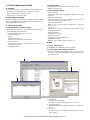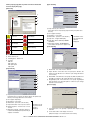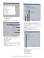
1
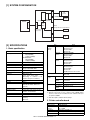
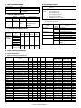
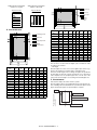
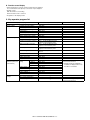
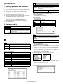
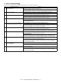
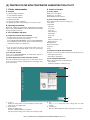
SERVICE MANUAL CODE: 00ZARP17//A1E DIGITAL MULTIFUNCTIONAL SYSTEM OPTION PRINTER EXPANSION KIT MODEL AR-PK1 AR-P17 CONTENTS [1] SYSTEM CONFIGURATION . . . . . . . . . . . . . . . . . . . . . . . . . . . . . . . . . . . 1-1 [2] SPECIFICATIONS . . . . . . . . . . . . . . . . . . . . . . . . . . . . . . . . . . . . . . . . . . . 1-1 [3] INSTALLATION . . . . . . . . . . . . . . . . . . . . . . . . . . . . . . . . . . . . . . . . . . . . . 3-1 [4] SETTING AND ADJUSTMENTS . . . . . . . . . . . . . . . . . . . . . . . . . . . . . . . . 4-1 [5] SIMULATION . . . . . . . . . . . . . . . . . . . . . . . . . . . . . . . . . . . . . . . . . . . . . . . 5-1 [6] CONFIGURATION REPORT AND TEST PAGE . . . . . . . . . . . . . . . . . . . . 6-1 [7] FLASH ROM VERSION UP PROCEDURE. . . . . . . . . . . . . . . . . . . . . . . . 7-1 [8] PRINTER STATUS MONITOR/PRINTER MANAGEMENT UTILITY . . . . 8-1 [9] TROUBLE CODE LIST . . . . . . . . . . . . . . . . . . . . . . . . . . . . . . . . . . . . . . . 9-1 [10] ELECTRICAL SECTION . . . . . . . . . . . . . . . . . . . . . . . . . . . . . . . . . . . . . 10-1 Parts marked with “ ” are important for maintaining the safety of the set. Be sure to replace these parts with specified ones for maintaining the safety and performance of the set. SHARP CORPORATION This document has been published to be used for after sales service only. The contents are subject to change without notice. CONTENTS [1] SYSTEM CONFIGURATION . . . . . . . . . . . . . . . . . . . . . . . . . 1-1 [2] SPECIFICATIONS [5] SIMULATION 1. Operating procedures and operations . . . . . . . . . . . . . . . 5-1 1. Basic specification . . . . . . . . . . . . . . . . . . . . . . . . . . . . . . . 1-1 2. Simulation code list . . . . . . . . . . . . . . . . . . . . . . . . . . . . . . 5-1 2. Printer controller board . . . . . . . . . . . . . . . . . . . . . . . . . . . 1-1 3. Details . . . . . . . . . . . . . . . . . . . . . . . . . . . . . . . . . . . . . . . . 5-1 3. IMC controller board . . . . . . . . . . . . . . . . . . . . . . . . . . . . . 2-1 [6] CONFIGURATION REPORT AND TEST PAGE 4. Network specification . . . . . . . . . . . . . . . . . . . . . . . . . . . . . 2-1 1. Kinds of test pages . . . . . . . . . . . . . . . . . . . . . . . . . . . . . . 6-1 5. Printer driver specification . . . . . . . . . . . . . . . . . . . . . . . . . 2-1 2. Print method . . . . . . . . . . . . . . . . . . . . . . . . . . . . . . . . . . . 6-1 A. System . . . . . . . . . . . . . . . . . . . . . . . . . . . . . . . . . . . . . 2-1 B. System requirement . . . . . . . . . . . . . . . . . . . . . . . . . . . 2-1 C. Print quality. . . . . . . . . . . . . . . . . . . . . . . . . . . . . . . . . . 2-1 D. Paper handling specifications. . . . . . . . . . . . . . . . . . . . 2-1 E. Print enable area . . . . . . . . . . . . . . . . . . . . . . . . . . . . . 2-2 F. Print reference . . . . . . . . . . . . . . . . . . . . . . . . . . . . . . . 2-2 [3] INSTALLATION 1. AR-P17 . . . . . . . . . . . . . . . . . . . . . . . . . . . . . . . . . . . . . . . 3-1 A. Parts included. . . . . . . . . . . . . . . . . . . . . . . . . . . . . . . . 3-1 B. Installation procedure . . . . . . . . . . . . . . . . . . . . . . . . . 3-1 C. Mounting of additional memory . . . . . . . . . . . . . . . . . . 3-2 2. AR-PK1 . . . . . . . . . . . . . . . . . . . . . . . . . . . . . . . . . . . . . . . 3-2 A. Parts included. . . . . . . . . . . . . . . . . . . . . . . . . . . . . . . . 3-2 B. Installation procedure . . . . . . . . . . . . . . . . . . . . . . . . . . 3-2 [4] SETTING AND ADJUSTMENTS 1. Printer condition settings . . . . . . . . . . . . . . . . . . . . . . . . . . 4-1 A. List . . . . . . . . . . . . . . . . . . . . . . . . . . . . . . . . . . . . . . . . 4-1 B. Operating procedure. . . . . . . . . . . . . . . . . . . . . . . . . . . 4-1 C. Setting item. . . . . . . . . . . . . . . . . . . . . . . . . . . . . . . . . . 4-1 2. AR-PK1 (PS expansion kit) setup . . . . . . . . . . . . . . . . . . . 4-2 A. Setup content . . . . . . . . . . . . . . . . . . . . . . . . . . . . . . . . 4-2 B. Setup enable conditions . . . . . . . . . . . . . . . . . . . . . . . . 4-2 C. Setup menu . . . . . . . . . . . . . . . . . . . . . . . . . . . . . . . . . 4-2 D. Function cancel menu . . . . . . . . . . . . . . . . . . . . . . . . . 4-2 3. Email alert status . . . . . . . . . . . . . . . . . . . . . . . . . . . . . . . . 4-2 A. Setup contents . . . . . . . . . . . . . . . . . . . . . . . . . . . . . . . 4-2 B. Setup enable conditions . . . . . . . . . . . . . . . . . . . . . . . . 4-2 C. Setup menu . . . . . . . . . . . . . . . . . . . . . . . . . . . . . . . . . 4-2 D. Function cancel display . . . . . . . . . . . . . . . . . . . . . . . . 4-3 4. Key operator program list. . . . . . . . . . . . . . . . . . . . . . . . . . 4-3 [7] FLASH ROM VERSION UP PROCEDURE 1. Printer Control Board firmware download method . . . . . . 7-1 2. Others (Troubleshooting) . . . . . . . . . . . . . . . . . . . . . . . . . 7-2 [8] PRINTER STATUS MONITOR/PRINTER ADMINISTRATION UTILITY 1. Printer status monitor . . . . . . . . . . . . . . . . . . . . . . . . . . . . 8-1 A. Purpose . . . . . . . . . . . . . . . . . . . . . . . . . . . . . . . . . . . . 8-1 B. Operating environment . . . . . . . . . . . . . . . . . . . . . . . . 8-1 C. V3.1 limitations and notes . . . . . . . . . . . . . . . . . . . . . . 8-1 D. Outline of functions . . . . . . . . . . . . . . . . . . . . . . . . . . . 8-1 2. Printer administration utility . . . . . . . . . . . . . . . . . . . . . . . . 8-3 A. Purpose . . . . . . . . . . . . . . . . . . . . . . . . . . . . . . . . . . . . 8-3 B. Operating environment . . . . . . . . . . . . . . . . . . . . . . . . 8-3 C. Outline of functions . . . . . . . . . . . . . . . . . . . . . . . . . . . 8-3 D. Note . . . . . . . . . . . . . . . . . . . . . . . . . . . . . . . . . . . . . . . 8-3 [9] TROUBLE CODE LIST . . . . . . . . . . . . . . . . . . . . . . . . . . . . . 9-1 [10] ELECTRICAL SECTION 1. Block diagram . . . . . . . . . . . . . . . . . . . . . . . . . . . . . . . . . 10-1 [1] SYSTEM CONFIGURATION PCL CONTROLLER CPU COPIER ENGINE System-BUS M B U S M B U S PCI-BUS 32bit/33MHz P C I U S B Ethernet USB2.0 (Full speed mode correspondence) PC 1 2 8 4 [2] SPECIFICATIONS Support OS (Printer Driver) 1. Basic specification Item Print Speed Resolution Smoothing Standard memory Expansion memory *2, 3 Option memory Toner save mode Input tray Duplex Print Finisher NIC PostScript Level3 *3 Bundled software Barcode font Operation Manual Platform Detail AR-M276/M277: 27ppm (600dpi) 13.5ppm (1200dpi) AR-M236/M237: 23ppm (600dpi) 13.5ppm (1200dpi) 300dpi, 600dpi, 1200dpi*1 1200dpi x 600dpi 64 MB DIMM 1 slot 144 pin 128/256MB DIMM 8MB flash DIMM Standard Multi Bypass tray Tray 1, Tray 2, Tray 3, Tray 4 (Depending on conditions of the machine and option installation.) Standard Option 10/100baseTX (Standard equipped with TCP/IP RF NIC. Others are optional.) Option Printer driver, PAU, Status monitor, Installer, Acrobat Reader Option Standard (Online manual) IBM PC/AT (Include compatible machine) Macintosh Option PCI Board 10/100BaseT L A N IO ASIC Energy-saving I/F correspondence P C I PC Item Custom PS Custom PCL5e Custom PCL6 PPD only PDL support Resident Fonts For PS Detail Windows 95/98/Me Windows NT 4.0 Windows 2000 Windows XP Windows 95/98/Me Windows NT 4.0 Windows 2000 Windows XP Windows 95/98/Me Windows NT 4.0 Windows 2000 Windows XP Windows 95/98/Me Windows NT 4.0 Windows2000 Windows XP MacOS 8.6 to 9.x, 10.1 or later PCL5e, PCL6, PostScript Level 3, TIFF, PDF 136 Outline Fonts For PCL5e, 80 Outline Fonts PCL6 Line Printer For PCL Barcode Fonts (Option) Screen Fonts For PS 136 Outline Fonts For PCL5e, 136 Outline Fonts PCL6 For PCL Barcode Fonts (Option) *1: 1200dpi mode print is supported only in PCL6 and PS3. *2: Network scan needs one slot of memory (max. 256MB). When, therefore, network scan is installed, the max. available memory for the printer is 320MB. *3: PDF direct print is available with PostScript. 2. Printer controller board Processor Base memory Expansion memory Parallel I/F USB I/F Network I/F AR-P17 SYSTEM CONFIGURATION 1 - 1 MIPS 64bit 64MB (Standard) Standard: 144 pin DIMM x 1 slot Max.: 320MB IEEE 1284 compatible x 1 USB 2.0 (Full speed mode correspondence) x 1 10/100baseTX x 1 3. IMC controller board Page memory ROPM Base memory ROPM Expansion memory B. System requirement 48MB 32MB Standard: 168 pin DIMM x 2 slot Max.: 1056MB Computer IBM PC/AT (Include compatible machine) Macintosh Operating system Microsoft Windows 95 Microsoft Windows 98 Microsoft Windows Me Microsoft Windows XP Microsoft Windows NT 4.0 Microsoft Windows 2000 MacOS 8.6 to 9.x, 10.1 or later 4. Network specification RF NIC AR-NC5J Interface 10Base-T 100Base-TX 10Base-T 100Base-TX Support OS Windows Support Protocol TCP/IP only NetWare, Windows NT, Mac OS IPX/SPX, TCP/IP, EtherTalk, Peer to Peer (IPX/SPX, TCP/IP), NetBEUI Note: Hardware requirements such as CPU and RAM for your operating system must be satisfied. C. Print quality Mode Resolution 5. Printer driver specification A. System Machine PCL6 PCL5e PostScript Custom Custom Custom OS IBM PC/AT Windows 95 (Include Windows 98 compatible Windows Me machine) Windows NT 4.0 Smoothing *1 PPD File Toner Save Mode *1 Yes Yes Yes Halftone enhancement *1 Yes Off Windows 2000 Windows XP Macintosh Controll (*: Default) 1200 dpi 600 dpi* 300 dpi On Off* On Off* On* Content High Quality Basic Resolution Alternate Resolution Smoothing function is ON. Smoothing function is OFF. Toner save function is ON. Toner save function is OFF. Halftone enhancement function is ON. Halftone enhancement function is OFF. *1: Functions on a image of 600dpi or 300dpi. MacOS8.6 to 9.x, 10.1 or later N/A N/A N/A Yes D. Paper handling specifications (1) Paper feed direction a. Paper size and image transfer direction Name A6R B6R Invoice Invoice-R A5 A5R B5 B5R Executive-R Letter Letter-R A4 A4-R Folio Legal Foolscap B4 A3 Ledger 8K 16K 16KR COM10 C5 DL Transparency Heavy stock Label Size mm (inch) Bypass Tray Tray 1 Tray 2 Tray 3 Tray 4 Duplex 105 × 148 128 × 182 215.9 × 139.7 (8.5” × 5.5”) 139.7 × 215.9 (5.5” × 8.5”) 210 × 148 148 × 210 257 × 182 182 × 257 186.7 × 266.7 (7.35” × 10.5”) 279.4 × 215.9 (11” × 8.5”) 215.9 × 279.4 (8.5” × 11”) 297 × 210 210 × 297 210 × 330 (8.3” × 13”) 215.9 × 355.6 (8.5” × 14”) 215.9 × 330.2 (8.5” × 13”) 257 × 364 297 × 420 279.4 × 431.8 (11” × 17”) 270 × 390 270 × 195 195 × 270 4.12 × 9.5 162 × 229 110 × 220 Yes Yes Yes Yes Yes Yes Yes Yes Yes Yes Yes Yes Yes Yes Yes Yes Yes Yes Yes Yes Yes Yes Yes Yes Yes Yes Yes Yes N/A N/A Yes N/A Yes N/A Yes Yes N/A Yes Yes Yes Yes N/A Yes Yes Yes Yes Yes Yes Yes Yes N/A N/A N/A N/A N/A N/A N/A N/A N/A N/A N/A N/A Yes Yes N/A Yes Yes Yes Yes N/A Yes Yes Yes Yes Yes Yes Yes Yes N/A N/A N/A N/A N/A N/A N/A N/A N/A N/A N/A N/A Yes Yes N/A Yes Yes Yes Yes N/A Yes Yes Yes Yes Yes Yes Yes Yes N/A N/A N/A N/A N/A N/A N/A N/A N/A N/A N/A N/A Yes Yes N/A Yes Yes Yes Yes N/A Yes Yes Yes Yes Yes Yes Yes Yes N/A N/A N/A N/A N/A N/A N/A N/A N/A N/A Yes N/A Yes Yes N/A Yes Yes Yes Yes N/A Yes Yes Yes Yes Yes Yes Yes Yes N/A N/A N/A N/A N/A N/A AR-P17 SPECIFICATIONS 2 - 1 Exit Tray Center Upper Tray Tray Yes Yes Yes Yes Yes Yes Yes Yes Yes Yes Yes Yes Yes Yes Yes Yes Yes Yes Yes Yes Yes Yes Yes Yes Yes Yes Yes Yes Yes Yes Yes Yes Yes Yes Yes Yes Yes Yes Yes Yes Yes Yes Yes Yes Yes Yes Yes Yes Yes Yes Yes Yes Yes Yes Yes Yes Top Tray N/A N/A Yes Yes Yes Yes Yes Yes Yes Yes Yes Yes Yes Yes Yes Yes Yes Yes Yes Yes Yes Yes N/A N/A N/A N/A N/A N/A 2tray Finisher Offset Staple Tray N/A N/A N/A N/A N/A N/A N/A N/A N/A N/A N/A N/A Yes Yes Yes N/A Yes N/A Yes Yes Yes Yes Yes Yes Yes Yes Yes N/A Yes Yes Yes Yes Yes Yes Yes Yes Yes Yes Yes N/A Yes N/A Yes N/A N/A N/A N/A N/A N/A N/A N/A N/A N/A N/A N/A N/A Setting direction toward paper feed port = Long side Setting direction toward paper feed port = Short side Transfer direction Transfer direction Actual page size Print area Logic paper size HP/GL picture frame E. Print enable area Actual page size Print area Logic paper size HP/GL picture frame Paper Size A3 B4 A4 B5 A5 Ledger Legal Letter Invoice Foolscap Folio Executive COM-10 C5 DL ∗ Top margin A B C D E F G H 9920 8597 7014 6070 4960 8400 8400 6600 5100 7800 7800 6300 5700 5408 5196 7014 6070 4960 4298 3508 5100 5100 5100 3300 5100 4980 4350 2474 3826 2598 9684 8361 6778 5830 4720 8160 8160 6360 2860 7560 7560 6060 3460 5172 4960 118 118 118 118 118 120 120 120 120 120 120 120 120 118 118 100 100 100 100 100 100 100 100 100 100 100 100 100 100 100 300 300 300 300 300 300 300 300 300 300 300 300 300 300 300 9720 8397 6814 5870 4760 8200 8200 6400 4900 7600 7600 6100 5500 5208 4996 0 0 0 0 0 0 0 0 0 0 0 0 0 0 0 The set value is received from the digital copier, and data are made according to the set value. A B C D E F G H 7014 6070 4960 4298 3508 6600 5100 5100 3300 5100 4980 4350 2474 3826 2598 9920 8597 7014 6070 4960 10200 8400 6600 5100 7800 7800 6300 5700 5408 5196 6730 5786 4676 5770 3224 6300 4800 4800 3000 4800 4680 4050 2174 3542 2314 142 142 142 142 142 150 150 150 150 150 150 150 150 142 142 100 100 100 100 100 100 100 100 100 100 100 100 100 100 100 300 300 300 300 300 300 300 300 300 300 300 300 300 300 300 6814 5870 4760 4098 3308 6400 4900 4900 3100 4900 4780 4150 2274 3626 2398 0 0 0 0 0 0 0 0 0 0 0 0 0 0 0 ∗ Left margin Since the paper size sensor is not set, the digital copier cannot recognize the size and direction of paper which is actually inserted. Therefore, the left margin is set according to the paper size specified in the print data sent from the computer, and print process is performed. If the computer does not specify the paper size, or in the case of the custom size, the left margin is set according to the default paper size. F. Print reference This machine employs the center reference system. Since the digital copier is not provided with the tray size detection feature, formatting and center distribution are performed not by the actual paper size but by the paper size specified by the computer. Origin Paper feed direction Paper Size A3 B4 A4 B5 A5 Ledger Legal Letter Invoice Foolscap Folio Executive COM-10 C5 DL AR-P17 SPECIFICATIONS 2 - 2 ABCDEFGHIJKLMN 12345 abc Actual paper size Size specified by the HOST Center reference line [3] INSTALLATION 2) Cut and remove the cut-out portion from the left rear cabinet. Cut and remove the cut-out portion from the left rear cabinet using a tool such as nippers. (Be careful about the direction of the tool so that the cut surface is flat.) 1. AR-P17 A. Parts included CD-ROM: 1 pc. Operation manual Installation caution sheet Cut-out portion PCL PWB: 1 pc. M3 screws: 3 pcs. (For installation of the parallel and the USB connectors) M3 screws with spring washer: 6 pcs. (For installation of the PCL PWB) 3) Attach the PCL PWB unit. Support post: 2 pcs. B. Installation procedure Attach the support post to the mounting plate of machine options. Then connect the PCL PWB connector to the mother board connector and fit the PCL PWB with the six screws with M3 spring washer (packed with the unit). Turn off the main switch of the copier and then remove the power plug of the copier from the outlet. Then, attach the parallel and USB connector portion using the supplied three screws. 1) Remove the shielding plate. Remove five screws and remove the shielding plate. M3 screws with spring washer Support post Screws M3 screw M3 screws PCL PWB M3 screws with spring washer Screws 4) Attach the shielding plate. Attach the shielding plate using five screws. Screws Screws AR-P17 INSTALLATION 3 - 1 Insert the power plug of the copier to the outlet and turn on the main switch. Then, carry out the following procedure. 5) Check for the PCL PWB. 3) Check the PS3. Make the following sequence of selections on the control panel. • Press Special Functions , highlight Configuration and press OK. Press the PRINT key on the operation panel to check to see if the copier enters the print mode. 6) Check for the language. Check for the language setting (26-22) following the procedure described in the service manual (section of simulation). 7) Check for printing. • Use the up and down keys to highlight Test print menu and press OK. • Use the up/down keys to highlight Configuration page and press OK. A configuration page will be printed. Check that the option memory capacity is 128 MB or more. For installation of printer drivers on a computer, see the supplied operation manual. Check that the PS3 has been installed. Then, connect a parallel cable to the computer and execute printing to check to see if printing can be executed properly. Please keep below important information. This information will use for other products. C. Mounting of additional memory (After mounting it, Installation proceed to step 4.) Insert the memory module until it clicks. The memory module is lock when it is inserted. However, be sure to check that the module slit is engaged with the connector rib when it is inserted. APPLICATION NUMBER MACHINE SERIAL NUMBER PRODUCT KEY Memory module (S.O.DIMM) 2. AR-PK1 A. Parts included CD-ROM: 1* License agreement Installation caution sheet *NOTE: Do not use the CD-ROM packed in AR-PK1, but use the CDROM packed together with the AR-P17 for setting the PS driver. B. Installation procedure To enable the PS3, the product key must be acquired. (For the method of acquiring the product key, contact the SHARP authorized dealer.) 1) Check that AR-P17 operates normally. • Turn on the power and wait until warming up is complete. • Press the PRINT key on the operation panel of the main unit. • If the LCD in the operation panel of the main unit switches to the print mode normally, AR-P17 is operating normally. • If it is not operating normally, follow the AR-P17 Installation Manual to check and modify the system configuration settings and check the operation. 2) Enable the PS3. To enable the system configuration, use the keys on the main unit to set the mode. Enter the product key with the key operator program. (Refer to the Operation Manual of Key Operator Program.) Setting of the product key is complete. To update the system, press the CA key to exit the setting mode. AR-P17 INSTALLATION 3 - 2 [4] SETTING AND ADJUSTMENTS 5) To terminate setting, touch the [END] key. CONDITION SETTINGS 1. Printer condition settings EXIT DEFAULT SETTINGS PCL SETTINGS A. List PostScript SETTINGS Item Default settings Toner save Copies Orientation Default paper size Default OFF 1 Portrait AB series: A4 Inch series: 8 1/2 x 11 Auto Auto OFF 600dpi OFF 1-sided ON OFF Default paper source Default paper type Smoothing Resolution Extra print mode 2-sided print Page protection ROPM PCL settings PCL symbol set setting PCL font setting Line feed code Wide A4 PostScript settings* Print PS errors 3 (PC-8) Internal font: 0 (courier) 0 OFF OFF * Displayed when installing the PS expansion kit (AR-PK1). B. Operating procedure 1) Press the [PRINT] key. The basic menu of the printer mode is displayed. COPY PRINT ON LINE DATA SCAN DATA 2) Touch the [CONDITION SETTINGS] key. Any print jobs that have already been sent to the machine, including print hold jobs stored in the machine, will be printed using the printer condition settings that were effect when the job was sent. ONLINE OFFLINE BYPASS SELECT CONDITION SETTINGS DELETE 3) Touch the target item to display the setting menu. EXIT CONDITION SETTINGS DEFAULT SETTINGS PCL SETTINGS PostScript SETTINGS 4) On the setting menu of the target item, set the desired set value and touch the [OK] key. To set another item continuously, repeat procedures 3) and 4). C. Setting item Default settings Set value Description (*: Default value) Toner save ON, OFF* Sets whether toner save mode is in effect or not. Toner is saved by printing a little lighter. When the resolution is 1200dpi, toner save does not function. Copies 1* – 999 Sets how many copies to print. Orientation Portrait*, Sets the page orientation for printing. Landscape Specify "PORTRAIT" to print the paper with its long side (longer edge) vertical. Specify "LANDSCAPE" to print the paper with its long side (longer edge) horizontal. Default 5 1/2 x 8 1/2, Sets the size of the paper where paper size 8 1/2 x11*, data will be printed. If this size is different from the paper size present 8 1/2 x 13, 8 1/2 x 14, in the tray, the size set for this item 11 x 17, A5, takes precedence. B5, A4*, B4, A3 * Depending on where the printer was purchased, the default value is either "A4" or "Letter". Default AUTO*, Sets the tray used for paper feeding. paper source BYPASS When set to "Auto," the tray loaded (MANUAL), with the paper set by "Default paper BYPASS (AUTO) size" is automatically selected. TRAY1, * Tray 3 and 4 (option) can be TRAY2, selected only when installed. TRAY3, TRAY4 Default AUTO*, PLAIN, Select the paper type to be used. paper type RECYLED, When set to "Auto," the tray loaded LETTER HEAD, with the paper set by "Default paper COLOUR size" is automatically selected. Sets whether smoothing is done or ON, OFF* Smoothing not. Angles and curves included in an image are smoothed to improve the image quality. If smoothing is set when the resolution is set to 600dpi, an image corresponding to 1200dpi is printed. (Printing at 1200dpi provides a higher print quality, but consumes a greater memory space, resulting in a low print speed. When the resolution is set to 1200dpi, smoothing cannot be selected.) To print a bitmap image, it is better not to select smoothing to have a better print quality. Resolution 300dpi, 600dpi*, Sets the printing resolution. When 1200dpi 1200dpi is selected, smoothing and toner save cannot be selected. Since 1200dpi printing consumes a large memory space, resulting in a low print speed. Item OK DEFAULT SETTINGS TONER SAVE COPIES 1 ORIENTATION P AR-P17 SETTING AND ADJUSTMENTS 4 - 1 Set value Description (*: Default value) Extra print ON, OFF* This function is used to reduce wait mode time between print jobs and proceeds efficient print processes mainly when there are many single print jobs. Normally it is not used. When this function is set, multiple print jobs are processed as a single job when all of the jobs have the same print format. On the job status display, it is displayed with one job key. When printing is made with the print hold function, this function does not work. When the print type is changed such as when the paper size is changed, this function is terminated. When "2-SIDED (BOOK)" is 2-sided print 1-SIDED*, 2-SIDED selected, duplex print is made on (BOOK), the assumption that the left edge of 2-SIDED paper is bound. When "2-SIDED (TABLET) (TABLET)" is selected, duplex print is made on the assumption that the top of paper is bound. Page ON*, OFF Sets page protection. Page protection protection is a function designed to prevent data loss errors when complex data is printed. Sets whether the ROPM function is ROPM ON, OFF* enabled. If the ROPM function is enabled, print data will be stored in the printer memory once for printing onto multiple sheets. This function can reduce transmission quantity between the printer and your computer. Item Wide A4 Set value Description (*: Default value) ON, OFF* When this item is set, 80 digits of 10CPI font can be printed in one line on A4 size paper. When setting is canceled, the print digit number in one line becomes 78 characters. PostScript settings "PS setting" is allowed only when the PS expansion kit is installed. Item Print PS errors Set value Description (*: Default value) ON, OFF* When it is set, if a PostScript error occurs, the error content is printed. 2. AR-PK1 (PS expansion kit) setup A. Setup content • The soft key is supplied by registering the manufacturing number and the model name of the machine and the application number attached to the PS expansion kit via the Web site. Enter the soft key to the machine, and the PS3 function can be operated. If, however, the setup enable conditions are not satisfied, inputs are disabled. • When the soft key is erroneously inputted: When the function lock is canceled: the function lock turns to work. When the function lock is working: the function lock is kept working. B. Setup enable conditions • The printer expansion kit (including the standard equipment) should be installed. • The Japanese font ROM should be installed to the printer board. (Japan only) • The printer function should be provided as standard provision. C. Setup menu PCL settings Set value Description (*: Default value) Specify the PCL symbol set. PCL symbol 1 – 35 (3*) set setting The number of the PCL symbol set can be checked by printing [PCL symbol set list] in [list print] of CUSTOM SETTING. PCL font Internal font The PCL font to be used for printing setting (0* – 80), can be specified. One type of font can extended font be selected from the internal fonts or (1 –) the expansion fonts (bar code font kit or flash ROM kit). The default is "0" (Internal font: Courier). The types of available fonts can be checked by printing the font list in the [list print] of the [CUSTOM SETTING]. The font list includes the font names, the numbers and print out sample assigned to the fonts. In this setting, the number assigned to the font to be used is set. Line feed 0* – 3 The line feed code is set by code combination of "CR" (Carriage Return) code, "LF" (Line Feed" code, and "FF" (Form Feed) code. The default is set so that printing is made by the sent code. To change the setting, there are four kinds of combination to select. Item Item Enter the soft key the machine from “KEY OPERATOR MENU". D. Function cancel menu • When the diag menu or the key operator program menu is displayed, the current machine state (the key is canceled or not) is displayed. • Display content ON: The function lock is working. OFF: The function lock is canceled. • Regardless of the display position 3. Email alert status A. Setup contents • The soft key is supplied by registering the manufacturing number and the model name of the machine and the fixed application number via the Web site. Enter the soft key to the machine, and the email alert and status function can be operated. If, however, the setup enable conditions are not satisfied, inputs are disabled. • When the soft key is erroneously inputted: When the function lock is canceled: the function lock turns to work. When the function lock is working: the function lock is kept working. B. Setup enable conditions • The printer expansion kit (including the standard equipment) should be installed. • The network card kit (NIC) should be installed. C. Setup menu Enter the soft key the machine from “KEY OPERATOR MENU". AR-P17 SETTING AND ADJUSTMENTS 4 - 2 D. Function cancel display • When the diag menu or the key operator program menu is displayed, the current machine state (the key is canceled or not) is displayed. • Display content ON: The function lock is working. OFF: The function lock is canceled. • Regardless of the display position 4. Key operator program list Key operator programs Print settings Default settings Interface settings Set value (∗: Default value) Prohibit notice page printing Print density level Prohibit test page printing Rotated print Forced output of print Exclude bypass-tray from ATS Disable default setting changes Hexadecimal dump mode I/O timeout Parallel port emulation switching USB port emulation switching Network port emulation switching Port switching method Network settings (When the print server card installed.) Initialise and/or store settings Enable parallel port Enable USB port Enable network port Enable ECP IP address DHCP setting IP address IP subnet mask IP gate way Enable TCP/IP *1) Enable NetWare *1) Enable EtherTalk *1) Enable NetBEUI *1) Reset the NIC Restore factory default Store current configuration Restore configuration ON / OFF∗ 1 / 2 / 3∗ / 4 / 5 ON / OFF∗ ON∗ / OFF ON / OFF∗ ON∗ / OFF ON / OFF∗ ON / OFF∗ 1 – 999 (Increment of 1sec.) 60 (sec.)∗ Auto∗ / PostScript (When the PS3 expansion kit is installed.) / PCL Auto∗ / PostScript (When the PS3 expansion kit is installed.) / PCL Auto∗ / PostScript (When the PS3 expansion kit is installed.) / PCL Switch at end of job∗ / Switch after I/O timeout ON∗ / OFF ON∗ / OFF ON∗ / OFF ON / OFF∗ ON∗ / OFF ON∗ / OFF ON∗ / OFF ON∗ / OFF ON∗ / OFF ON∗ / OFF ON∗ / OFF ON∗ / OFF — — — — AR-P17 SETTING AND ADJUSTMENTS 4 - 3 Remarks To enable the changed setup, the power must be rebooted. *1) Displayed when the AR-NC5J is installed. Not displayed when only the AR-P17 is installed. To enable the changed setup, the power must be rebooted. [5] SIMULATION 24-9 1. Operating procedures and operations Purpose Function (Purpose) * Entering the simulation mode 1) #/P key (program) ON → Asterisk (*) key ON → CLEAR key ON → Asterisk (*) key ON → Ready for input of a main code of simulation 2) Entering a main code with the 10-key → START key ON 3) Entering a sub code with the 10-key → START key ON Data clear Used to clear the printer counter and other counters. (The counter is cleared after completion of maintenance.) Section Printer Item Counter Printer Operation/procedure 1. Select the counter to be cleared with the 10-key. 4) Select an item with the scroll key and the item key. 5) The machine enters the mode corresponding to the selected item. Press START key to start the simulation operation. 2. Press the [START] key. The confirmation menu is shown. 3. Select "1: YES." To cancel the current simulation mode or to change the main code and the sub code, press the CUSTOM SETTINGS key. 1: YES (Cleared) 2: NO (Not cleared) (Default) * Canceling the simulation mode to return to the normal mode 1) Press CLEAR ALL key. 1 2 3 4 2. Simulation code list Code Main Sub 22 1 24 9 67 14 Item PRINTER IMC DUPLEX OTHERS Content Printer counter IMC counter DUPLEX counter The other counters Function Used to check the counter value of each section. Used to clear the printer counter and other counters. (The counter is cleared after completion of maintenance.) Used to check write/comparison of flash programs. 67-14 3. Details Purpose Flash ROM version up Function Used to check write/comparison of flash programs. (Purpose) Section Printer Item Operation Operation/procedure 22 22-1 Purpose Function (Purpose) Item Adjustment/setting/operation data output/check (display/print) Used to check the counter value of each section. Counter Operation/procedure Each counter is displayed. TOTAL MAINTENANCE DEVE DRUM COPY PRINTER IMC DUPLEX OTHERS FAX SEND FAX RCV FAX OUTPUT Total Maintenance Developer counter *1 Drum counter Copy counter Printer counter IMC counter Duplex counter The other counters FAX Send counter FAX receive counter FAX print counter 1. Press the [START] key. "PLEASE SEND DATA" is displayed. 2. Data are sent from the PC (MS-DOS) by use of "fcopy" command (FCOPY: file name). (Refer the “[ 7] FLASH ROM VERSION UP PROCEDURE”) Used to overwrite and check the flash device while displaying its process status. After completion, the result is displayed. 3. Press the [CA] key to cancel the simulation and reset. (Flash Device) PROGRAM BOOTROM PS KANJI FONT ESC/P KANJI FONT OPTION FONT (Processing state) RECEIVE ERASE WRITE VERIFY * Execution of the simulation which performs communication with the PCL board is inhibited until Notice Page storage is completed. (Only when the serviceman call error occurs.) In the other case than the serviceman call error, entering the simulation is inhibited during the system check operation is displayed. The counter display is in 7 digits. AR-P17 SIMULATION 5 - 1 [6] CONFIGURATION REPORT AND TEST PAGE 1. Kinds of test pages 2) Touch the [LIST PRINT] key. Test pages are available in the following 6 kinds: • Printer settings list • PCL symbol set list Y T LIST PRINT S • PCL internal font list • PCL extended font list (Only when an option font or an option Flash ROM kit is installed. When a Flash ROM kit is installed, it is displayed only when fonts are downloaded.) • PCL internal font list (With PS installed) • PS extended font list (Displayed only when PS is installed, an option Flash ROM is installed, and fonts are downloaded.) RECEIVE MODE 3) Touch the [PRINTER TEST PAGE] key. PRINTER TEST PAGE • NIC page 2. Print method 1) Press the [CUSTOM SETTINGS] key. 4) Touch the list key to be printed. LINE DATA B STATUS CUSTOM SETTINGS PRINTER SETTINGS LIST PCL INTERNAL FONT LIST PCL SYMBOL SET LIST PCL EXTENDED FONT LIST * It is printed by priority even when there is a job waiting for printing. AR-P17 CONFIGURATION REPORT AND TEST PAGE 6 - 1 [7] FLASH ROM VERSION UP PROCEDURE 1. Printer Control Board firmware download method Please follow the procedure below: (Necessary items for version-up) 1) Make sure copier is turned off, and connect PC and Printer Control board of the copier by parallel cable beforehand. A Personal computer B Centro (printer) cable ∗ Note: It is okay to use serial cable instead. C Software for version-up 2) Turn on the copier. 3) Start up in copier test command mode, and execute Sim67-14 "FLASHDOWNLOAD". 4) And then, press OK key when notice message "PRESS OK KEY" appears on the panel. Another message "Please Send Data" will appear after a while. 5) Start up the maintenance program on PC. Select model name "AR-M236/M276/M237/M277 Series" from the model selection dialogue box. 6) Expand "Printer Control Board", and double-click on "Printer Control Board Firmware Download". (ROM type) The flash ROM is directly installed to each PWB. (Target PWB) 1 PCL PWB Outline of Version-up Procedure (PC) C A Download data RS232C connector (9pin or 25pin) Centro connector B Centro cable I/F circuit (9pin) MCU-PWB Double click it. Centro connector PCL-PWB 1 Operation panel IMC PWB FAX-PWB Finisher 7) Dialog box will appear to select download file. 8) Select Download file(*.sfu) and press "Open" button. 9) Download procedure will starts automatically. (AR-M236/M276/M237/M277) Prepare following files necessary for program download • Maintenance software: maintenance.exe • Andromeda module file: ProcModelC.mdl (for AR-M236/M276/ M237/M277 series) 10) Notice message "Data Send Complete" will appear on PC. 11) Notice message "Download is complete. Check the copier panel to make sure the download is complete." will appear on PC. 12) Close maintenance program, and reset the machine by pressing CA key. This is the end of the download procedure. AR-P17 FLASH ROM VERSION UP PROCEDURE 7 - 1 2. Others (Troubleshooting) Followings are the error possibly occur during the download process and troubleshooting method. No 1 Warning/error message Incorrect destination. Continue with the download process? 2 Incorrect download file. 3 No downloadable data included. 4 This option not available. 5 The data size exceeds the Flash ROM size. Try again with the appropriate size of data. 6 Time out error. 7 Communication (incoming) error. 8 Checksum error. 9 Error during the download process. Error code: 0xXXXXXXXX 10 An error. [0xXXXXXXXX] Detail Destination of download file and copier doesn't match. Possible to select either continue or cancel the job. [TROUBLESHOOTING] To change destination, select "Yes". If not, select "No" and cancel download process. Invalid download file for the machine is selected, or the file format is not correct. [TROUBLESHOOTING] Confirm the download file. Possibly the improper download file is selected. Unable to find appropriate data in selected download file. [TROUBLESHOOTING] Confirm the download file. Possibly the improper download file is selected. Download procedure is executed on uninstalled optional kit. [TROUBLESHOOTING] Confirm installed optional kit. Confirm the download file. Possibly the improper download file is selected. Panel flash ROM size is not enough to execute download procedure. [TROUBLESHOOTING] Confirm the download file. Possibly the improper download file is selected. Exchange the flash ROM to the one which has more capacity. Transmission error Unable to receive data from the machine among the certain period of time. [TROUBLESHOOTING] Restart maintenance program after confirming communication port or communication cable. Incorrect download procedure. The machine did not proceed download procedure correctly. [TROUBLESHOOTING] Restart maintenance program after confirming communication port or communication cable. Make sure the communication device of PC(either COM or parallel) is under right condition. Transmission error The check sum value of the transmission data is mismatch. [TROUBLESHOOTING] Restart maintenance program after confirming communication device of PC (either COM or parallel) is under right condition. Download data file operation error. [TROUBLESHOOTING] Restart maintenance program after confirming the selected download file is not abnormal and not using other application. The error occurred except the above errors. [TROUBLESHOOTING] Restart maintenance program after confirming communication device of PC(either COM or parallel) is under right condition. AR-P17 FLASH ROM VERSION UP PROCEDURE 7 - 2 [8] PRINTER STATUS MONITOR/PRINTER ADMINISTRATION UTILITY 1. Printer status monitor D. Outline of functions A. Purpose (1) Status display • Is printing enabled or disabled? Simple view: For beginners • Is toner sufficiently supplied? Detailed view: For experts • Is paper sufficiently supplied? Simple/Detailed selection allowed • Is duplex print enable? (2) Status change notification • Is the previous printing completed? Device status when the machine is sending a job This application provides easy and simple view of the above items. Print enable B. Operating environment Print disable Windows95, Windows98, WindowsMe, WindowsNT4.0 Workstation (SP3 or later), Windows2000 Professional, Windows XP Home Edition Professional TCP/IP necessary C. V3.1 limitations and notes Paper jam Toner empty Toner Low Printer Warning Paper Empty (1) Requisites of printer to be monitored Cover open • The printer driver should have been installed. (Necessary) Off-line • The driver should allow peer-to-peer printing. For the AR-M237/M277/M236/M276 series, the SC-Print2000 (Windows 95/98/Me) should be installed, and the "Print destination port" of the printer should be set to TCP/IP port, Printer error (Service call) Output Tray Full Notifying method: Status window pop-up or • In the case where the driver is shared with the printer server, the printer should be connected with TCP/IP. In this case, monitoring is allowed after printing once. Tip pop-up Sound (3) Selection of printer to be monitored (2) Install and uninstall The printer to be monitored can be switched by the following two ways. In the case of WindowsNT/2000/XP, the administrator authority is required for install and uninstall. • Switch by the printer menu (3) Status display when in the auto power shut off (4) Job complete notification The status information when the printer is in the "Auto power shut off" mode is the status information immediately before entering the "Auto power shut off mode. Status of the job which was sent by the machine • Switch by the setting dialog Print complete Temporary interruption of print by an error 1) 2) 3) 4) 1) Tool bar Displays the status window, revises the display to the latest state, makes setups, and displays Help. 3) Tip Turns on for a certain time (when setting) when the status changes. 2) Status window Displays the printer status. Selection of Simple/Detailed view is allowed. Pop-up to indicate a change in the status is also allowed by setup. 4) Task tray icon Memory-resident. Displays the printer status which is monitored. AR-P17 PRINTER STATUS MONITOR/PRINTER MANAGEMENT UTILITY 8 - 1 (6) Job complete notification When a print job is completed (or interrupted by an error), a notification from the printer is received and displayed. The dialog pop-up shows the notification. 1) 2) 1) 2) 3) 3) 4) 4) 5) 5) 6) 6) 7) 1) "Normal" icon 4) Printer driver name 2) Message 5) Job name 1) "Error" icon 5) Job name 6) "CLOSE" button 2) Message 6) "CLOSE" button 3) Notifying time 7) "DETAIL" button 3) Notifying time 4) Printer driver name (7) Status advice immediately before printing (23-page machine/27-page machine) If any trouble occurs The status is checked when printing is performed. The dialog to select Continue or Cancel printing is displayed. AR-P17 PRINTER STATUS MONITOR/PRINTER MANAGEMENT UTILITY 8 - 2 2. Printer administration utility (2) Alert/log function • Alert by the pop-up/sound when the printer status changes. A. Purpose • Making of the alert/log file This application provides easy and simple view of the following items: • What kinds of network printers are connected in the network? • Are the network printers operating normally? • What functions does the printer have? B. Operating environment Windows 95, Windows 98, Windows Me, Windows NT4.0 Workstation (SP3 or later)/2000 Professional, Windows XP Home Edition Professional TCP/IP, Winsock2 necessary C. Outline of functions (1) Network printer retrieval/list display • Retrieval and list display of the network printers which conform to the Printer MIB (RFC1759) specifications. • Printer status display by the color of the icon – Normal state (No color) On-line – Warning state (Yellow) Paper low, toner near empty, printer warning – Error state (Red) Paper empty, cover open, toner empty, paper jam, printer error, Specified output tray full • List display filter function (3) Printer property display • Device information Model name, status, name, installing place, RAM size, max. print speed, etc. • Paper exit tray information Tray name, number of trays, paper empty/presence of each tray, paper exit method, printing sequence, etc. • Paper feed tray information Number of trays, tray name, paper empty/presence of each tray, paper size etc, • Print setup Channel & PDL information, default PDL, paper direction, single/ duplex print information • Resource information Print quantity, toner status • Summary information Information on the system and network • SHARP NIC information NetWare setup, IP address, hardware address, etc. D. Note (1) Install and uninstall For NT/2000/XP, the administrator authority is required. (2) Status display when auto power shut off • The various information when the printer is in the "Auto power shut off" mode is information immediately before entering the "Auto power shut off mode. 1) 2) 3) 1) Main window List display of network printers. The status of a printer is indicated by the color of the icon. 2) Printer property page Detailed information (on the functions and status) of a printer is displayed. 3) Pop-up alert The pop-up-alert can be displayed by the setup when the printer status changes. AR-P17 PRINTER STATUS MONITOR/PRINTER MANAGEMENT UTILITY 8 - 3 Printer property page (Select a printer from the list and double click it to display this page.) [Paper feed tab] [Device tab] 1) 2) 3) 1) 4) 2) Toner Low Toner Empty Offline Paper Jam Paper Empty Printer Error Cover Open Printer Warning 5) 3) 6) 4) 7) 1) Paper feed tray for normal use: If the driver does not specify any paper feed tray, the printer uses this tray. 2) List of paper feed trays: 3) Description: = Tray name 4) Model name: (Not set in some models.) Information on the tray selected from 5) Paper size: Length x width (mm) the list is 6) Paper kind: Name defined by ISO/IEC displayed. 10175DPA 7) Max. paper capacity: AR-M230/M270 series detects the presence of paper only. [Print setup tab] Specified Output Tray Full 1) 2) 1) Model 2) Name: Can be set. 3) 3) Installing place: Can be set. 4) Property: RM size Max. paper size Max. print speed Paper path 4) [Paper exit tab] 1) Channel list: List of the effective channels 1) 2) Paper direction: If the driver does not specify the direction, the printer uses this direction for normal use. (No change allowed for some models.) 2) 3) 3) Default PDL: If the driver does not specify any PDL, the printer uses this PDL for normal use. (No change allowed for some models.) 4) 5) 4) Single/Duplex print: If the driver does not specify single/duplex print, the printer uses this print path for normal use. (No change allowed for some models.) [Resource type] 6) 7) 2) 1) Paper exit tray for normal use: If the driver does not specify any paper exit tray, the printer uses this tray. No change allowed for some models. 2) List of paper output trays: 3) Description: = Tray name 4) Model name: (Not set in some models.) 5) Paper exit method: Face-up or face-down Information on the tray selected from 6) Printing sequence: "First To Last" or "Last the list is To First" displayed. 7) Max. paper capacity: The paper presence is detected and displayed only when the job separator is installed. 1) 1) Total Impressions: The quantity of printouts and outputs of copy and FAX. 2) Toner status: OK or toner empty or toner low. (Only toner empty or not is detected in some models.) AR-P17 PRINTER STATUS MONITOR/PRINTER MANAGEMENT UTILITY 8 - 4 [Summary tab] Setup [Application] 1) 1) Network and device information: Device information – Descriptions, operating time, etc. Network information – TCP, IP, the number of send/receive packet of SNMP [SHARP NIC tab] 1) 2) 3) 1) Setup: Used to set that the icon is minimized when booting or not, and that the setup content is stored when terminating or not. 1) 2) 3) 2) Network printer retrieval interval: Used to set automatic retrieval of a printer on the network. The printers to be retrieved can be set with the "Printer retrieval (TCP/IP)" tab. The retrieval interval is 1min to 60min. The default is 3min. 3) State and alert revision interval: Used to set automatic revision of the printer status. The revision interval is 10sec to 90sec. The default is 30sec. [Confirmation] 4) 1) NetWare setup: Setup of NetWare enable/disable If set to enable, setup and display and changes are made on the following items: NDS mode or Bindery mode NDS tree name, context name Bindery server name Print server name Ethernet frame name 2) TCP/IP setup: TCP/IP address, sub-net mask, default gateway 3) Hardware address: Hardware address of the network card in the target printer. 4) Link to the device Web page (Provided only the models which have an assembly Web server.) 1) 1) Confirmation message: Used to set that the confirmation pop-up menu is displayed when; the device setup is changed. the device is deleted, the filter setup is deleted, the log file is deleted, the application is terminated. AR-P17 PRINTER STATUS MONITOR/PRINTER MANAGEMENT UTILITY 8 - 5 [Printer retrieval (TCP/IP)] 1) 2) 3) 1) Printer retrieval on the local network: When this box is checked, the local network address is obtained from the IP address and the sub net mask of the PC where PAU is installed, and a printer on the local network is retrieved. 3) Advanced retrieval dialog box Used to set the printer retrieval on an external network. To specify an external network to be retrieved, enter the network address and the sub net mask of that network. 2) Retrieval by IP address: A certain IP address can be obtained. Only when this box is checked, the printers which have IP addresses listed on the list can be retrieved. System diagram Manager PAU Printer status monitor User Printer status monitor User Printer status monitor User Printer status monitor User Printer status monitor User Printer status monitor User AR-P17 PRINTER STATUS MONITOR/PRINTER MANAGEMENT UTILITY 8 - 6 [9] TROUBLE CODE LIST Trouble code Main Sub code code F9 00 Details of trouble Content Details Cause Check and remedy 10 Content Details Cause Check and remedy 80 Content Details Cause Check and remedy 81 Trouble code Main Sub code code F9 82 Content Details Cause Check and remedy MCU-PRT communication trouble Communication establishment error/ framing/parity/protocol error Printer PWB connector disconnection Harness trouble between the printer PWB and the MCU PWB Motherboard connector pin breakage Printer PWB ROM trouble/Data disturbance Check the connectors and harness of the printer PWB and MCU PWB. Check the grounding of the copier. Check ROM on printer PWB. Printer PWB trouble Communication trouble between MCU and printer PWB Printer PWB connector disconnection Harness trouble between the printer PWB and the MCU PWB Motherboard connector pin breakage Printer PWB ROM trouble/Data disturbance Check the connectors and harness of the printer PWB and MCU PWB. Check the grounding of the copier. Check ROM on printer PWB. Printer PWB communication trouble (Protocol) Communication trouble between MCU and printer PWB (Protocol error) Printer PWB connector disconnection Harness trouble between the printer PWB and the MCU PWB Motherboard connector pin breakage Printer PWB ROM trouble/Data disturbance Check the connectors and harness of the printer PWB and MCU PWB. Check the grounding of the copier. Check ROM on printer PWB. Printer PWB communication trouble (Parity) Communication trouble between MCU and printer PWB (Parity error) Printer PWB connector disconnection Harness trouble between the printer PWB and the MCU PWB Motherboard connector pin breakage Printer PWB ROM trouble/Data disturbance Check the connectors and harness of the printer PWB and MCU PWB. Check the grounding of the copier. Check ROM on printer PWB. Details of trouble Content Details Cause Check and remedy 84 Content Details Cause Check and remedy 88 Content Details Cause Check and remedy 99 AR-P17 TROUBLE CODE LIST 9 - 1 Content Details Cause Check and remedy Printer PWB communication trouble (Overrun) Communication trouble between MCU and printer PWB (Overrun error) Printer PWB connector disconnection Harness trouble between the printer PWB and the MCU PWB Motherboard connector pin breakage Printer PWB ROM trouble/Data disturbance Check the connectors and harness of the printer PWB and MCU PWB. Check the grounding of the copier. Check ROM on printer PWB. Printer PWB communication trouble (Framing) Communication trouble between MCU and printer PWB (Framing error) Printer PWB connector disconnection Harness trouble between the printer PWB and the MCU PWB Motherboard connector pin breakage Printer PWB ROM trouble/Data disturbance Check the connectors and harness of the printer PWB and MCU PWB. Check the grounding of the copier. Check ROM on printer PWB. Printer PWB communication trouble (Timeout) Communication trouble between MCU and printer PWB (Timeout error) Printer PWB connector disconnection Harness trouble between the printer PWB and the MCU PWB Motherboard connector pin breakage Printer PWB ROM trouble/Data disturbance Check the connectors and harness of the printer PWB and MCU PWB. Check the grounding of the copier. Check ROM on printer PWB. Machine-PCL board language error The machine language setup does not coincide with the PCL board language setup. PCL board connection error SIM setup error Check the firmware of the PCL board and the combination of the panel screen data, and download the correct version, if necessary. Check the machine language information. (Machine language setup: SIM 26-22) [10] ELECTRICAL SECTION PCI connector 1. Block diagram TMPR4927 ADDR[19:0] PCI BUS 32bit/33MHz SDRAM 64MB DATA [31:0] DATA[63:0] DATA [63:0] PIO SDRAM-DIMM 128MB or 256MB RJ45 SPD PIO DP83816 (MAC/PHY) EEPROM 256Kb Flash DIMM 12MB DATA[31:0] Flash-DIMM 8MB(Option) DATA[31:0] Driver DATA[31:0] UART1 (Japan Only) For Debug IO ASIC(Unicorn2) UART0 Connector M-BUS Driver DATA[15:0] Connector Energy-saving I/F correspondence USB2.0(FS) ML60852A System Bus I/F 1284 Cont. Image Cont. RTC I/F IO I/F PIO USB2.0 (Full speed mode correspondence) AR-P17 ELECTRICAL SECTION 10 - 1 1284 Driver Connector Connector MROM-DIMM 32MB(PS Font) q PARTS GUIDE CODE:00ZARP17//P1/ プリンタ コントローラー PRINT CONTROLLER MODEL AR-P17 このパーツガイドに掲載されている表示価格ランクは消費税抜きです。 CONTENTS 1 梱包&付属品 (Packing material & Accessories) 2 PCL PWB UNIT(PCL PWB UNIT) ■ 索引 (Index) 本書はサービス活動用に作成した資料です。 一部内容が製品の改良・改善等により予告 なしに変わることがあります。 SHARP CORPORATION This document has been published to be used for after sales service only. The contents are subject to change without notice. 補修部品のランク付 市場における補修部品の在庫管理が、適正に運営出来る手助けとなることを、目的とします。 Aランク : メンテナンスパーツ、メンテナンスパーツには入っていないがメンテナンスパーツに近い消耗パーツ。 Bランク : 性能・機能パーツ(センサー、クラッチ等の電気パーツ) 、消耗パーツ。 Eランク : 基板含むユニットパーツ。 Dランク : 整備パーツ(外装、パッキング、同梱パーツ)。 Cランク : 上記ランク以外のパーツ(基板の子部品を除いたもの) 。 DEFINITION Rank Rank Rank Rank Rank A B E D C : : : : : Maintenance parts, and consumable parts which are not included in but closely related to maintenance parts Performance/function parts (sensors, clutches, and other electrical parts), consumable parts Unit parts including PWB Preparation parts (External fitting, packing, parts packed together) Parts other than the above (excluding sub components of PWB) 安全性・信頼性確保のため部品は、必ず正規のものをご使用下さい。 ! 印の商品は、安全上重要な部品です。交換をする時は、安全及び性能維持のため必ず指定の部品をご使用下さい。 Because parts marked with "!" is indispensable for the machine safety maintenance and operation, it must be replaced with the parts specific to the product specification. F F F F 当モデルのサービス資料には、この資料以外にサービスマニュアル ( 回路図含む ) があります。合わせてご利用下さい。 Other than this Parts Guide, please refer to documents Service Manual(including Circuit Diagram)of this model. Please use the 13 digit code described in the right hand corner of front cover of the document, when you place an order. For U.S. only-Use order codes provided in advertising literature. Do not order from parts department. 1 梱包&付属品 (Packing material & Accessories) NO. PARTS CODE 1 CDSKA0033QS31 4 SPAKA399ACCZZ 6 TCADZ0288QSZZ TINSJ1076QSZZ TINSE1077QSZZ 7 TINSF1078QSZZ TINSS1079QSZZ 9 LX-BZ0024QSZZ 10 SSAKA0006UCZZ 11 XBPSD30P06KS0 101 LSUPM0002QSZZ 102 VHI29L12802QS PRICE RANK Ex. Ja. BA FX AB DD AD DJ AQ EQ AP EQ AS EQ AS EQ AA DD AA DD AA DD AE DJ BQ LP NEW MARK N N N N N N N N PART RANK D D D D D D D C D C C B DESCRIPTION CD ROM J Vinyl bag Inst.manual OPE.manual OPE.manual OPE.manual OPE.manual Screw(3×8) Vinyl bag(50×60mm) Screw(3×6KS) Support post PRG DIMM –1– [Japan] CD ROM J ポリ袋 [Except USA,Canada,LAG] 設置手順書 [Japan] 取扱説明書 [ENGLISH] 取扱説明書 [FRENCH] 取扱説明書 [SPANISH] 取扱説明書 ビス ポリ袋 ビス サポートポスト 7 [Japan] PRG DIMM 1 梱包&付属品 (Packing material & Accessories) 10 9 4 11 2 3 1 5 7 6 PRP01669 2 PCL PWB UNIT(PCL PWB UNIT) NO. 1 3 4 5 6 9 11 12 13 14 15 16 18 19 20 21 22 25 26 28 29 30 32 33 34 35 36 37 PARTS CODE QCNCM0041QSZZ QCNCW0025QSZZ QCNCW0071GCZZ QCNCW7045XCZZ QSOCN0010QSZZ QSOCZ0079FCZZ RCILZ0353AFZZ RCORF1013ACZZ RCORF1057ACZZ RCRUA0019QSZZ RCRUA0020QSZZ RFILN0010QSZZ RH-IX1013ACZZ RMPTR4103ACZZ RMPTR4103ACZZ RMPTR4330ACZZ RMPTR4330ACZZ RMPTR4330ACZZ RMPTR4330ACZZ RMPTR4472ACZZ RMPTR4560ACZZ VCCCCZ1HH100D VCCCCZ1HH101J VCCCCZ1HH680J VCCUCY1AJ105Z VCEAPH1CC106M VCEAPS1CC226M VCEAPZ1CW107M VCEAPZ1CW477M VCKYCZ1AB683K VCKYCZ1CB103K VCKYCZ1CB103K VCKYCZ1CF104Z PRICE RANK Ex. Ja. AP EQ AL EB AH DX AG DS AV FG AN EQ AH DX AD DJ AB DJ AR EQ AL EB AB DD BK HC AB DD AB DD AB DD AB DD AB DD AB DD AB DD AA DD AA DD AA DD AA DD AC DD AC DD AC DJ AD DJ AE DS AB DD AA DD AA DD AB DD NEW MARK N N N PART RANK C C C C C C C C C B B C B B B B B B B B B C C C C C C C C C C C C DESCRIPTION Connector(TX25-100P12) Connector(TX24-60R-12) Connector(57pin) Connector(USB) Socket(RJ-45) Socket(100pin) Chock coil(PLP3216S121SL2) Core(BLM41P600S) Ferrite beads(BLM21P221SG) Crystal(25.00M OSC) Crystal(12.00M OSC) Noise filtet(BLM18BB121SN1D) IC(SDRAM 256M) Block resistor(10KΩ×4) Block resistor(10KΩ×4) Block resistor(33Ω×4) Block resistor(33Ω×4) Block resistor(33Ω×4) Block resistor(33Ω×4) Block resistor(4.7KΩ×4) Block resistor(56Ω×4) Capacitor(50WV 10pF) Capacitor(50WV 100pF) Capacitor(50WV 68pF) Capacitor(10WV 1.0µF) Capacitor(16WV 10µF) Capacitor(16WV 22µF) Capacitor(16WV 100µF) Capacitor(16WV 470µF) Capacitor(10WV 68µF) Capacitor(16WV 0.010µF) Capacitor(16WV 0.010µF) Capacitor(16WV 0.10µF) –2– [CN3] [CN9] [CN11] [CN10] [CN12] [Japan][CN8] [L1] [L10∼13] [L2] [X1] [X2] [L3∼6,14,15] [IC5,6] [RN27,41,44,49,51] [RN54,56,58,60] [RN1,2,6,8,20,22,23,25,26] [RN28∼40,42,43,45∼48] [RN50,52,53,55,57,59] [RN65,66,67,68,71∼76] [RN24,61∼64,69,70] [RN3,4,5,7,9∼19,21] [C91] [C61∼67,72∼88] [C3,209,210] [C96] [C113,145,146] [C39,90,114] [C4] [C46,47] [C147,150] [C97∼105,108,110,112] [C118,120,205,215] [C1,2,6∼38,40,42∼45] コネクター コネクター コネクター コネクター ソケツト ソケツト チョークコイル コア フェライトビーズ クリスタル クリスタル ノイズフイルタ IC ブロックテイコウ ブロックテイコウ ブロックテイコウ ブロックテイコウ ブロックテイコウ ブロックテイコウ ブロックテイコウ ブロックテイコウ コンデンサー コンデンサー コンデンサー コンデンサー コンデンサー コンデンサー コンデンサー コンデンサー コンデンサー コンデンサー コンデンサー コンデンサー 2 PCL PWB UNIT(PCL PWB UNIT) NO. 37 38 39 40 44 46 47 48 49 50 51 52 53 54 55 56 57 58 59 60 61 62 63 64 65 66 67 68 69 70 71 72 73 74 75 76 PARTS CODE VCKYCZ1CF104Z VCKYCZ1CF104Z VCKYCZ1CF104Z VCKYCZ1CF104Z VCKYCZ1HB102K VHDD1FM3+++-1 VHIDP83816+-1 VHIPST598IN-1 VHI24WC256K-1 VHI60852ATB-1 VHI74LCX08FT1 VHI74LCX14FT1 VHI74LCX244FT VHI74LCX245FT VHI74LVX16128 VHI93C46VI+-1 VHPLT1P67A+-1 VHVICPS1.2/-1 VRS-CZ1JD000J VRS-CZ1JD000J VRS-CZ1JD000J VRS-CZ1JD100J VRS-CZ1JD100J VRS-CZ1JD100J VRS-CZ1JD102J VRS-CZ1JD102J VRS-CZ1JD103J VRS-CZ1JD103J VRS-CZ1JD103J VRS-CZ1JD103J VRS-CZ1JD121J VRS-CZ1JD152J VRS-CZ1JD153J VRS-CZ1JD220J VRS-CZ1JD221J VRS-CZ1JD302J VRS-CZ1JD330J VRS-CZ1JD330J VRS-CZ1JD330J VRS-CZ1JD330J VRS-CZ1JD330J VRS-CZ1JD470J VRS-CZ1JD471J VRS-CZ1JD472J VRS-CZ1JD472J VRS-CZ1JD472J VRS-CZ1JD472J VRS-CZ1JD560J VRS-CZ1JD822J VRS-TS2AD220J VRS-TX2HDR24J VRSCY1JR49R9F VRSCY1JR54R9F VSDTC114YK/-1 PRICE RANK Ex. Ja. AB DD AB DD AB DD AB DD AA DD AD DJ BE GN AF DS AV FG AX FG AF DS AF DS AH DX AH DX AP EQ AE DS AC DJ AF DS AA DD AA DD AA DD AA DD AA DD AA DD AA DD AA DD AA DD AA DD AA DD AA DD AA DD AA DD AA DD AA DD AA DD AA DD AA DD AA DD AA DD AA DD AA DD AA DD AA DD AA DD AA DD AA DD AA DD AA DD AA DD AA DD AA DD AA DD AA DD AC ZZ NEW MARK N N PART RANK C C C C C B B B B B B B B B B B B B C C C C C C C C C C C C C C C C C C C C C C C C C C C C C C C C C C C B DESCRIPTION Capacitor(16WV 0.10µF) Capacitor(16WV 0.10µF) Capacitor(16WV 0.10µF) Capacitor(16WV 0.10µF) Capacitor(50WV 1000pF) Diode(DIFM3) IC(DP83816) IC(PST598IN) EEPROM(24WC256K) IC(60852ATB) IC(74LCX08FT1) IC(74LCX14FT1) IC(TC74LCX244) IC(74LCX245FT) IC(74LVX16128) IC(93C46VI) Diode(LT1P67A) IC protecrot(ICPS1.2) Resistor(1/16W 0Ω ±5%) Resistor(1/16W 0Ω ±5%) Resistor(1/16W 0Ω ±5%) Resistor(1/16W 10Ω ±5%) Resistor(1/16W 10Ω ±5%) Resistor(1/16W 10Ω ±5%) Resistor(1/16W 1.0KΩ ±5%) Resistor(1/16W 1.0KΩ ±5%) Resistor(1/16W 10KΩ ±5%) Resistor(1/16W 10KΩ ±5%) Resistor(1/16W 10KΩ ±5%) Resistor(1/16W 10KΩ ±5%) Resistor(1/16W 120Ω ±5%) Resistor(1/16W 1.5KΩ ±5%) Resistor(1/16W 15KΩ ±5%) Resistor(1/16W 22Ω ±5%) Resistor(1/16W 220Ω ±5%) Resistor(1/16W 300KΩ ±5%) Resistor(1/16W 33Ω ±5%) Resistor(1/16W 33Ω ±5%) Resistor(1/16W 33Ω ±5%) Resistor(1/16W 33Ω ±5%) Resistor(1/16W 33Ω ±5%) Resistor(1/16W 47Ω ±5%) Resistor(1/16W 470Ω ±5%) Resistor(1/16W 4.7KΩ ±5%) Resistor(1/16W 4.7KΩ ±5%) Resistor(1/16W 4.7KΩ ±5%) Resistor(1/16W 4.7KΩ ±5%) Resistor(1/16W 56Ω ±5%) Resistor(1/16W 8.2KΩ ±5%) Resistor(1/10W 22Ω ±5%) Resistor(1/2W 0.24Ω ±5%) Resistor(1/10W 49.9Ω ±5%) Resistor(1/10W 54.9Ω ±5%) Transistor(DTC114YK) –3– [C48∼53,68∼71,89] [C92∼95,115∼117,119] [C121,124∼140,143,144] [C152∼204,206,208,214] [C106,107,109,111,148,149] [D2] [IC24] [IC31] [IC3] [IC21] [IC2] [IC4] [IC8,10,12,15,20,30] [IC7,9,11,13,18,19] [IC22] [IC26] [D1] [F1] [R85∼92,165∼176] [R180∼184,189,197,209] [R213,214,248,255∼257] [R94,136∼150,187,205,219] [R220,223∼226,229∼232] [R245,267∼274] [R2∼6,18,32,34∼37] [R156,157,247] [R17,19,26,29,30,31,38,39,95] [R99,110∼113,118,120,121] [R158,159,178,179,185,186] [R204,206,210,263,264,291] [R100] [R160] [R228] [R24] [R154] [R227] [R9,10,13∼16,20∼23,25,42] [R43,45,46,50,51,53,55,56] [R57,59,60∼66,93,102∼109] [R114∼117,119,258,260∼262] [R265,266,275∼287] [R44,47,48,49,243] [R188,198] [R40,41,52,69,70] [R74∼76,101,123,124] [R151,152,155,161] [R217,221,246,249] [R54,96,97,98] [R27,28,77∼84] [R162,163,164] [R222] [R190,200] [R193,202] [TR1] コンデンサー コンデンサー コンデンサー コンデンサー コンデンサー ダイオード IC IC EEPROM IC IC IC IC IC IC IC ダイオード IC プロテクター テイコウ テイコウ テイコウ テイコウ テイコウ テイコウ テイコウ テイコウ テイコウ テイコウ テイコウ テイコウ テイコウ テイコウ テイコウ テイコウ テイコウ テイコウ テイコウ テイコウ テイコウ テイコウ テイコウ テイコウ テイコウ テイコウ テイコウ テイコウ テイコウ テイコウ テイコウ テイコウ テイコウ テイコウ テイコウ トランジスター ■ 索引 (Index) PARTS CODE [C] CDSKA0033QS31 [L] LSUPM0002QSZZ LX-BZ0024QSZZ [Q] QCNCM0041QSZZ QCNCW0025QSZZ QCNCW0071GCZZ QCNCW7045XCZZ QSOCN0010QSZZ QSOCZ0079FCZZ [R] RCILZ0353AFZZ RCORF1013ACZZ RCORF1057ACZZ RCRUA0019QSZZ RCRUA0020QSZZ RFILN0010QSZZ RH-IX1013ACZZ RMPTR4103ACZZ RMPTR4330ACZZ RMPTR4472ACZZ RMPTR4560ACZZ [S] SPAKA399ACCZZ SSAKA0006UCZZ [T] TCADZ0288QSZZ TINSE1077QSZZ TINSF1078QSZZ TINSJ1076QSZZ TINSS1079QSZZ [V] VCCCCZ1HH100D VCCCCZ1HH101J VCCCCZ1HH680J VCCUCY1AJ105Z VCEAPH1CC106M VCEAPS1CC226M VCEAPZ1CW107M VCEAPZ1CW477M VCKYCZ1AB683K VCKYCZ1CB103K VCKYCZ1CF104Z VCKYCZ1HB102K VHDD1FM3+++-1 VHI24WC256K-1 VHI29L12802QS VHI60852ATB-1 VHI74LCX08FT1 VHI74LCX14FT1 VHI74LCX244FT VHI74LCX245FT VHI74LVX16128 VHI93C46VI+-1 VHIDP83816+-1 VHIPST598IN-1 VHPLT1P67A+-1 VHVICPS1.2/-1 VRSCY1JR49R9F VRSCY1JR54R9F VRS-CZ1JD000J VRS-CZ1JD100J VRS-CZ1JD102J VRS-CZ1JD103J VRS-CZ1JD121J VRS-CZ1JD152J VRS-CZ1JD153J VRS-CZ1JD220J VRS-CZ1JD221J VRS-CZ1JD302J VRS-CZ1JD330J VRS-CZ1JD470J VRS-CZ1JD471J VRS-CZ1JD472J VRS-CZ1JD560J VRS-CZ1JD822J VRS-TS2AD220J PARTS CODE PRICE R. NEW P/R Ex. Ja. JAPAN ONLY ORDER CODE NO. 578 966 0138 1- 1 BA FX N D 578 233 0027 578 970 0222 1- 101 1- 9 AE AA DJ DD N C C 578 510 0271 578 510 0243 578 510 0211 578 510 0250 578 527 0033 578 527 0029 222222- 1 3 4 5 6 9 AP AL AH AG AV AN EQ EB DX DS FG EQ 596 614 0565 596 615 0063 596 615 0149 578 616 0072 578 616 0073 578 621 0076 596 573 4270 567 631 0100 567 631 0109 567 631 0102 596 631 0499 22222222222- 11 12 13 14 15 16 18 19 20 21 22 AH AD AB AR AL AB BK AB AB AB AA DX DJ DJ EQ EB DD HC DD DD DD DD 505 902 5004 541 906 1016 1- 4 1- 10 AB AA DD DD 572 913 1007 578 916 0817 578 916 0818 578 916 0833 578 916 0819 11111- 6 7 7 7 7 AD AP AS AQ AS DJ EQ EQ EQ EQ 521 593 0027 521 593 0028 567 593 0316 596 593 0899 521 594 0001 593 594 0584 567 594 0133 575 594 0013 572 593 0354 595 593 1450 521 593 0017 521 593 0030 523 570 0014 578 573 1200 578 573 1359 572 573 2910 521 573 0491 572 573 2024 521 573 0388 594 573 1659 578 573 1048 578 573 1358 567 573 1648 523 573 0081 578 574 0048 567 577 0014 567 581 0630 596 581 3342 521 581 0082 567 581 0524 521 581 0093 521 581 0085 567 581 0526 521 581 0175 567 581 0528 567 581 0532 567 581 0533 572 581 2072 521 581 0202 521 581 0170 567 581 0617 521 581 0088 572 581 2084 572 581 2066 500 581 5044 2- 25 2- 26 2- 28 2- 29 2- 30 2- 32 2- 33 2- 34 2- 35 2- 36 2- 37 2- 38 2- 39 2- 46 1- 102 2- 47 2- 48 2- 49 2- 50 2- 51 2- 52 2- 53 2- 40 2- 44 2- 54 2- 55 2- 74 2- 75 2- 56 2- 57 2- 58 2- 59 2- 60 2- 61 2- 62 2- 63 2- 64 2- 65 2- 66 2- 67 2- 68 2- 69 2- 70 2- 71 2- 72 AA AA AA AC AC AC AD AE AB AA AB AA AD AV BQ AX AF AF AH AH AP AE BE AF AC AF AA AA AA AA AA AA AA AA AA AA AA AA AA AA AA AA AA AA AA DD DD DD DD DD DJ DJ DS DD DD DD DD DJ FG LP FG DS DS DX DX EQ DS GN DS DJ DS DD DD DD DD DD DD DD DD DD DD DD DD DD DD DD DD DD DD DD N N N C C C C C C C C C B B C B B B B B D D N N N N N N N D D D D D C C C C C C C C C C C C B B B B B B B B B B B B B B C C C C C C C C C C C C C C C C C C C –4– VRS-TX2HDR24J VSDTC114YK/-1 [X] XBPSD30P06KS0 JAPAN ONLY ORDER CODE NO. PRICE R. NEW P/R Ex. Ja. 578 581 0720 507 576 5005 2- 73 2- 76 AA AC DD ZZ 541 970 0016 1- 11 AA DD N C B C LEAD-FREE SOLDER CAUTION FOR BATTERY REPLACEMENT The PWB’s of this model employs lead-free solder. The “LF” marks indicated on the PWB’s and the Service Manual mean “Lead-Free” solder. The alphabet following the LF mark shows the kind of lead-free solder. Example: Lead-Free 5mm (Danish) ADVARSEL ! Lithiumbatteri – Eksplosionsfare ved fejlagtig håndtering. Udskiftning må kun ske med batteri af samme fabrikat og type. Levér det brugte batteri tilbage til leverandoren. (English) Caution ! Danger of explosion if battery is incorrectly replaced. Replace only with the same or equivalent type recommended by the manufacturer. Dispose of used batteries according to manufacturer’s instructions. Solder composition code (Refer to the table at the right.) (Finnish) VAROITUS Paristo voi räjähtää, jos se on virheellisesti asennettu. Vaihda paristo ainoastaan laitevalmistajan suosittelemaan tyyppiin. Hävitä käytetty paristo valmistajan ohjeiden mukaisesti. a z (French) ATTENTION Il y a danger d’explosion s’ il y a remplacement incorrect de la batterie. Remplacer uniquement avec une batterie du même type ou d’un type équivalent recommandé par le constructeur. Mettre au rebut les batteries usagées conformément aux instructions du fabricant. Sn-In-Ag-Bi i (Swedish) Sn-Cu-Ni n Sn-Ag-Sb s Bi-Sn-Ag-P Bi-Sn-Ag p <Solder composition code of lead-free solder> Solder composition Solder composition code Sn-Ag-Cu a Sn-Ag-Bi Sn-Ag-Bi-Cu b Sn-Zn-Bi (1) NOTE FOR THE USE OF LEAD-FREE SOLDER THREAD When repairing a lead-free solder PWB, use lead-free solder thread. Never use conventional lead solder thread, which may cause a breakdown or an accident. Since the melting point of lead-free solder thread is about 40°C higher than that of conventional lead solder thread, the use of the exclusiveuse soldering iron is recommendable. (2) NOTE FOR SOLDERING WORK Since the melting point of lead-free solder is about 220°C, which is about 40°C higher than that of conventional lead solder, and its soldering capacity is inferior to conventional one, it is apt to keep the soldering iron in contact with the PWB for longer time. This may cause land separation or may exceed the heat-resistive temperature of components. Use enough care to separate the soldering iron from the PWB when completion of soldering is confirmed. Since lead-free solder includes a greater quantity of tin, the iron tip may corrode easily. Turn ON/OFF the soldering iron power frequently. If different-kind solder remains on the soldering iron tip, it is melted together with lead-free solder. To avoid this, clean the soldering iron tip after completion of soldering work. If the soldering iron tip is discolored black during soldering work, clean and file the tip with steel wool or a fine filer. VARNING Explosionsfara vid felaktigt batteribyte. Använd samma batterityp eller en ekvivalent typ som rekommenderas av apparattillverkaren. Kassera använt batteri enligt fabrikantens instruktion. (German) Achtung Explosionsgefahr bei Verwendung inkorrekter Batterien. Als Ersatzbatterien dürfen nur Batterien vom gleichen Typ oder vom Hersteller empfohlene Batterien verwendet werden. Entsorgung der gebrauchten Batterien nur nach den vom Hersteller angegebenen Anweisungen. CAUTION FOR BATTERY DISPOSAL (For USA, CANADA) "BATTERY DISPOSAL" THIS PRODUCT CONTAINS A LITHIUM PRIMARY (MANGANESS DIOXIDE) MEMORY BACK-UP BATTERY THAT MUST BE DISPOSED OF PROPERLY. REMOVE THE BATTERY FROM THE PRODUCT AND CONTACT YOUR LOCAL ENVIRONMENTAL AGENCIES FOR INFORMATION ON RECYCLING AND DISPOSAL OPTIONS. "TRAITEMENT DES PILES USAGÉES" CE PRODUIT CONTIENT UNE PILE DE SAUVEGARDE DE MÉMOIRE LITHIUM PRIMAIRE (DIOXYDE DE MANGANÈSE) QUI DOIT ÊTRE TRAITÉE CORRECTEMENT. ENLEVEZ LA PILE DU PRODUIT ET PRENEZ CONTACT AVEC VOTRE AGENCE ENVIRONNEMENTALE LOCALE POUR DES INFORMATIONS SUR LES MÉTHODES DE RECYCLAGE ET DE TRAITEMENT. All rights reserved. Printed in Japan. No part of this publication may be reproduced, stored in a retrieval system, or transmitted, in any form or by any means, electronic; mechanical; photocopying; recording or otherwise without prior written permission of the publisher. Trademark Acknowledgments Microsoft Windows, MS-DOS, Windows NT, Windows 2000 are trademarks of Microsoft Corporation in the U. S. A. and other countries. Macintosh, Power Macintosh, Mac OS, LaserWriter, and AppleTalk are registered trademarks of Apple Computer, Inc. IBM, PC/ AT, and PowerPC are trademarks of International Business Machines Corporation. Pentium is a registered trademark of Intel Corporation. PCL is a trademark of the Hewlett- Packard Company. PostScript is a registered trademark of Adobe Systems Incorporated. NetWare is a registered trademark of Novell, Inc. All other trademarks and copyrights are the property of their respective owners. SHARP CORPORATION Digital Document System Group Products Quality Assurance Department Yamatokoriyama, Nara 639-1186, Japan 2003 August Printed in Japan