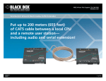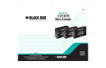
1
MARCH 2002
ACS250A
ACS251A
Customer Support Information:
FREE tech support 24 hours a day, 7 days a week: Call 724-746-5500 or fax 724-746-0746.
Mailing address: Black Box Corporation, 1000 Park Dr., Lawrence, PA 15055-1018
World-Wide Web: www.blackbox.com • E-mail: [email protected]
© Copyright 2002. Black Box Corporation. All rights reserved.
THE SERVSWITCH™ FAMILY
Welcome to the ServSwitchTM Family!
Thank you for purchasing a BLACK BOX® ServSwitch™ Brand KVM Extender
model! We appreciate your business, and we think you’ll appreciate the many ways
that your enhanced keyboard/video/mouse system will save you money, time, and
effort.
That’s because our ServSwitch family is all about breaking away from the
traditional, expensive model of computer management. You know, the one-sizefits-all-even-if-it-doesn’t model that says, “One computer gets one user station, no
more, no less.” Why not a single user station (monitor, keyboard, and mouse) for
multiple computers—even computers of different platforms? Why not a pair of
user stations, each of which can control multiple computers? Why not multiple
user stations for the same computer?
With our ServSwitch products, there’s no reason why not. We carry a broad line
of robust solutions for all these applications. Do you have just two PCs, and need
an economical alternative to keeping two monitors, keyboards, and mice on your
desk? Or do you need to share dozens of computers, including a mix of IBM® PC,
RS/6000®, Apple® Macintosh®, Sun Microsystems®, and SGI® compatibles among
multiple users with different access levels? Does your switch have to sit solidly on a
worktable and use regular everyday cables? Or does it have to be mounted in an
equipment rack and use convenient many-to-one cables? No matter how large or
small your setup is, no matter how simple or how complex, we’re confident we
have a ServSwitch system that’s just right for you.
The ServSwitch™ family from Black Box—the one-stop answer for all your KVMswitching needs!
*
This manual will tell you all about your new ServSwitch™ Brand Fiber KVM
Extender II or II-SM, including how to install, operate, and troubleshoot it. For an
introduction to the Extender, see Chapter 2. The Extender product codes covered
in this manual are:
ACS250A
ACS251A
1
SERVSWITCH™ BRAND FIBER KVM EXTENDER II AND II-SM
TRADEMARKS USED IN THIS MANUAL
BLACK BOX and the
logo are registered trademarks, and ServSwitch is a
trademark, of Black Box Corporation.
Apple and Macintosh are registered trademarks of Apple Computer, Inc.
IBM, PC/AT, and PS/2 are registered trademarks of International Business
Machines Corporation.
Microsoft and Intellimouse are registered trademarks or trademarks of Microsoft
Corporation in the United States and/or other countries.
Sun and Sun Microsystems are registered trademarks of Sun Microsystems, Inc. in
the United States and other countries.
Any other trademarks mentioned in this manual are acknowledged to be the property of the
trademark owners.
2
FCC/IC STATEMENTS
FEDERAL COMMUNICATIONS COMMISSION AND INDUSTRY CANADA
RADIO-FREQUENCY INTERFERENCE STATEMENTS
This equipment generates, uses, and can radiate radio-frequency energy, and if not
installed and used properly, that is, in strict accordance with the manufacturer’s
instructions, may cause interference to radio communication. It has been tested
and found to comply with the limits for a Class A computing device in accordance
with the specifications in Subpart B of Part 15 of FCC rules, which are designed to
provide reasonable protection against such interference when the equipment is
operated in a commercial environment. Operation of this equipment in a
residential area is likely to cause interference, in which case the user at his own
expense will be required to take whatever measures may be necessary to correct the
interference.
Changes or modifications not expressly approved by the party responsible for
compliance could void the user’s authority to operate the equipment.
This digital apparatus does not exceed the Class A limits for radio noise emission from digital
apparatus set out in the Radio Interference Regulation of Industry Canada.
Le présent appareil numérique n’émet pas de bruits radioélectriques dépassant les limites
applicables aux appareils numériques de la classe A prescrites dans le Règlement sur le
brouillage radioélectrique publié par Industrie Canada.
3
SERVSWITCH™ BRAND FIBER KVM EXTENDER II AND II-SM
EUROPEAN UNION DECLARATION OF CONFORMITY
This is to certify that, when installed and used according to the instructions in this
manual together with the specified cables, the ServSwitch™ Brand Fiber KVM
Extender II and II-SM are shielded against the generation of radio interference in
accordance with the application of Council Directive 89/336/EEC.
The Extenders were tested in a typical configuration.
LASER-SAFETY STATEMENT
To meet laser-safety requirements, the Extender operates its optical transceivers
within their maximum ratings. The transceivers must always be terminated with an
optical connector or dust cap. For full optical specifications, see Chapter 1.
CAUTION!
Using lenses, magnifying glasses, or other optical instruments with this
product could pose extreme eye hazards. All necessary adjustments
have already been made at the factory prior to the shipment of the
Extender. Even if it doesn’t result in damage or injury (which is likely),
tampering with or modifying the Extender, or changing the way it
performs, could void the Extender’s original certifications.
4
NOM STATEMENT
NORMAS OFICIALES MEXICANAS (NOM)
ELECTRICAL SAFETY STATEMENT
INSTRUCCIONES DE SEGURIDAD
1. Todas las instrucciones de seguridad y operación deberán ser leídas antes de
que el aparato eléctrico sea operado.
2. Las instrucciones de seguridad y operación deberán ser guardadas para
referencia futura.
3. Todas las advertencias en el aparato eléctrico y en sus instrucciones de
operación deben ser respetadas.
4. Todas las instrucciones de operación y uso deben ser seguidas.
5. El aparato eléctrico no deberá ser usado cerca del agua—por ejemplo, cerca
de la tina de baño, lavabo, sótano mojado o cerca de una alberca, etc.
6. El aparato eléctrico debe ser usado únicamente con carritos o pedestales que
sean recomendados por el fabricante.
7. El aparato eléctrico debe ser montado a la pared o al techo sólo como sea
recomendado por el fabricante.
8. Servicio—El usuario no debe intentar dar servicio al equipo eléctrico más allá
a lo descrito en las instrucciones de operación. Todo otro servicio deberá ser
referido a personal de servicio calificado.
9. El aparato eléctrico debe ser situado de tal manera que su posición no
interfiera su uso. La colocación del aparato eléctrico sobre una cama, sofá,
alfombra o superficie similar puede bloquea la ventilación, no se debe colocar
en libreros o gabinetes que impidan el flujo de aire por los orificios de
ventilación.
10. El equipo eléctrico deber ser situado fuera del alcance de fuentes de calor
como radiadores, registros de calor, estufas u otros aparatos (incluyendo
amplificadores) que producen calor.
11. El aparato eléctrico deberá ser connectado a una fuente de poder sólo del
tipo descrito en el instructivo de operación, o como se indique en el aparato.
5
SERVSWITCH™ BRAND FIBER KVM EXTENDER II AND II-SM
12. Precaución debe ser tomada de tal manera que la tierra fisica y la polarización
del equipo no sea eliminada.
13. Los cables de la fuente de poder deben ser guiados de tal manera que no
sean pisados ni pellizcados por objetos colocados sobre o contra ellos,
poniendo particular atención a los contactos y receptáculos donde salen del
aparato.
14. El equipo eléctrico debe ser limpiado únicamente de acuerdo a las
recomendaciones del fabricante.
15. En caso de existir, una antena externa deberá ser localizada lejos de las lineas
de energia.
16. El cable de corriente deberá ser desconectado del cuando el equipo no sea
usado por un largo periodo de tiempo.
17. Cuidado debe ser tomado de tal manera que objectos liquidos no sean
derramados sobre la cubierta u orificios de ventilación.
18. Servicio por personal calificado deberá ser provisto cuando:
A: El cable de poder o el contacto ha sido dañado; u
B: Objectos han caído o líquido ha sido derramado dentro del aparato; o
C: El aparato ha sido expuesto a la lluvia; o
D: El aparato parece no operar normalmente o muestra un cambio en su
desempeño; o
E: El aparato ha sido tirado o su cubierta ha sido dañada.
6
TABLE OF CONTENTS
Contents
Chapter
Page
1.
Specifications ............................................................................................. 8
2.
Introduction .............................................................................................
2.1 Overview ............................................................................................
2.2 Key Features ......................................................................................
2.3 The Complete Package .....................................................................
3.
Compatibility and Signal Processing ...................................................... 13
3.1 Video Processing ................................................................................ 13
3.2 Mouse Compatibility ......................................................................... 14
3.3 Sound Processing .............................................................................. 14
4.
Installation ................................................................................................
4.1 Guidelines and Limitations for Attaching Equipment ...................
4.1.1 CPU ..........................................................................................
4.1.2 Monitor ....................................................................................
4.1.3 Keyboard and Mouse ..............................................................
4.2 An Extender Installation Illustrated ................................................
4.3 Installing the Local Unit and Local Devices ...................................
4.4 Installing the Remote Unit and Remote Devices ............................
4.5 Finishing Your Installation ...............................................................
5.
Operation ................................................................................................. 22
6.
Troubleshooting ...................................................................................... 23
6.1 Calling Black Box ............................................................................... 23
6.2 Shipping and Packaging ................................................................... 23
11
11
12
12
15
15
15
15
15
16
17
19
21
7
SERVSWITCH™ BRAND FIBER KVM EXTENDER II AND II-SM
1. Specifications
Cable Required: ACS250A: 50/125-µm or (to lesser distances) 62.5/125-µm
multimode duplex fiberoptic cable;
ACS251A: 9/125-µm single-mode duplex fiberoptic cable
Compliance:
CE; FCC Part 15 Subpart B Class A, IC Class/classe A
Interfaces:
Extension:
ACS250A: Duplex multimode fiberoptic;
ACS251A: Duplex single-mode fiberoptic;
Video: VGA compatible (DOS mode, VGA, SVGA, XGA,
SXGA); Plug-and-Play for monitors and DDC not
supported;
Keyboard and mouse: IBM PS/2 compatible;
Sound: 3.5-mm stereo audio
Resolution and
Refresh Rate:
Supports resolutions up to 1280 x 1024 and refresh rates
up to 75 Hz; maximum pixel clock (bandwidth) is
108 MHz
Optical Type and
Wavelength:
ACS250A: 850-nm multimode;
ACS251A: 1300-nm single-mode
Transmitter
Launch Power:
Receiver
Sensitivity:
Optical
Budget:
8
ACS250A: Into either 50-µm or 62.5-µm cable: From –4.5 to
–9 dBm;
ACS251A: Into 9-µm cable: From –3 to –9 dBm
ACS250A:
With 62.5-µm cable: –12.5 dBm;
With 50-µm cable: –13.5 dBm;
ACS251A: –14.4 dBm
ACS250A:
With 62.5-µm cable: 6.7 dB maximum;
With 50-µm cable: 7.5 dB maximum;
ACS251A: 10.5 dB maximum
CHAPTER 1: Specifications
Maximum
Distance:
Between Extender’s Local and Remote Units:
ACS250A:
Over 62.5-µm cable: 220 m (720 ft.);
Over 50-µm cable: 400 m (1310 ft.);
ACS251A: 10 km (6.2 mi.)
User Controls:
None
Indicators:
(1) Front-mounted green LED on each Unit:
Local Unit: LED is steadily lit during normal operation,
flashes if Unit is powered but no video signal is present
at VGA input;
Remote Unit: LED is steadily lit during normal
operation, flashes if no fiber connection is detected or
Local Unit is outputting no signal
Connectors:
On Local Unit:
Front-mounted:
(4) 6-pin mini-DIN female:
(1) for CPU’s keyboard port;
(1) for CPU’s mouse port;
(1) for optional local keyboard;
(1) for optional local mouse;
(1) HD15 female for CPU’s video port;
(1) HD15 female for optional local monitor;
(1) 3.5-mm stereo audio jack (~0.7 Veff/~2 Vpp) for
CPU’s audio-out port;
Rear-mounted:
(1) Duplex SC female for fiber link (transmitter on
left, receiver on right);
(1) 2.1-mm barrel jack for power;
(1) 8-pin mini-DIN for service (reserved for
manufacturer use);
On Remote Unit:
Front-mounted:
(2) 6-pin mini-DIN female:
(1) for remote keyboard;
(1) for remote mouse;
(1) HD15 female for remote monitor;
(1) 3.5-mm stereo audio jack (~0.7 Veff/~2 Vpp) for
remote audio device (outputs mono on both stereo
channels);
9
SERVSWITCH™ BRAND FIBER KVM EXTENDER II AND II-SM
Connectors
(continued):
Temperature
Tolerance:
On Remote Unit (continued):
Rear-mounted:
(1) Duplex SC female for fiber link (transmitter on
left, receiver on right);
(1) 2.1-mm barrel jack for power;
(1) 8-pin mini-DIN for service (reserved for
manufacturer use)
Operating: 50 to 104˚F (10 to 40˚C);
Storage: 32 to 158˚F (0 to 70˚C)
Humidity
Tolerance:
Up to 70% noncondensing
Enclosure:
Aluminum
Power:
From utility-power (mains) outlet, through detachable
input cord and IEC 320 male inlet to external
transformer:
Input: 100 to 264 VAC, 50 to 60 Hz, autosensing, at up to
~200 mA at 115 VAC or ~100 mA at 230 VAC;
Output: 12 VDC at up to 2 amps (Local Unit draws only 1
amp maximum, Remote Unit only 1.1 amps);
Consumption:
Local Unit: 14 watts maximum;
Remote Unit: 12 watts maximum
Size:
Each Unit: 2.6"H x 7.3"W x 7.1"D (6.6 x 18.6 x 18 cm)
Weight:
Net, Local Unit: 2.4 lb. (1.1 kg);
Net, Remote Unit: 2.2 lb. (1 kg);
Shipping: Approximately 10 lb. (4.5 kg)
10
CHAPTER 2: Introduction
2. Introduction
2.1 Overview
There are many KVM extenders available, but until now many of them have used
analog image transmission, which inherently degrades image quality (especially
over long distances and at high video resolutions).
The ServSwitch™ Brand Fiber KVM Extender II and II-SM is a digital imagetransmission system. Video output from a local computer CPU is automatically
digitized by the Extender’s Local Unit and transmitted serially to the Remote Unit
on a single fiber at data rates up to 1.5 Gbps. The Remote Unit converts the digital
signal back into the original analog signal. Up to the maximum specified cable
lengths, image quality is independent of cable length.
The Extender uses its second fiber to send remote mouse and keyboard
information back to the local CPU. The Extender needs only these two fibers for
full operation. Compared with some analog KVM extenders that require as many
as five fibers, the Fiber KVM Extender II and II-SM can save you significant
amounts of money, especially if you’ll need to run fiber cable across long distances.
There are two models of the Extender:
• The Fiber KVM Extender II (ACS250A) is the multimode model. It transmits
digital video up to 220 m (720 ft.) across 62.5/125-µm multimode fiber or up
to 400 m (1310 ft.) across multimode fiber.
• The Fiber KVM Extender II-SM (ACS251A) is the single-mode model. It
transmits digital video up to 10 km (6.2 mi.) across 9/125-µm single-mode fiber.
In addition to the keyboard, video, and mouse information, the Local Unit can
also digitize optional sound information from a local CPU or other audio device
and encode it into the digital information sent to the Remote Unit on the video
fiber. The sound quality won’t approach high fidelity (it will be converted to
monaural if it’s stereo), but will be roughly equivalent to that of sound transmitted
over the telephone, which is sufficient for error messages and so forth.
You can also connect an optional local user station (keyboard, monitor, and
mouse only) to the Local Unit. The Local Unit will pass video through to the local
monitor and will switch the keyboard and mouse. (This means that the local user
contends with the remote user for keyboard and mouse control of the CPU: Once
the active user station is idle for 2 seconds, the first user to type at the keyboard or
move the mouse will be granted control.)
11
SERVSWITCH™ BRAND FIBER KVM EXTENDER II AND II-SM
2.2 Key Features
• Digital transmission of video, keyboard, mouse, and optional audio
information on only two fibers over distances up to 400 m (1310 ft.) of
multimode cable or 10 km (6.2 mi.) of single-mode cable.
• Supports an optional local monitor, keyboard, and mouse user station that
contends with the remote station for CPU control.
• Supports several of the most common VGA-compatible video standards (DOS
mode, VGA, XGA, SVGA, or SXGA) at resolutions up to 1280 x 1024 or output
refresh rates up to 75 Hz.
• Automatic adjustment of all transmission and image parameters—you don’t
have to configure it.
• All cables you would normally need except for the fiber cable are included.
2.3 The Complete Package
At the time of this writing, your Extender package should consist of:
• The Extender’s Local Unit.
• The Extender’s Remote Unit.
• (2) Power supplies with 6-ft. (1.8-m) nondetachable output cords, one for each
Unit.
• (2) Input cords, one for each power supply; length might vary depending on
region and source, but is normally 6 ft. (1.8 m).
• (1) 6-ft. (1.8-m) VGA-extension cable with HD15 male connectors at both
ends.
• (2) 6.6-ft. (2-m) PS/2® extension cables with 6-pin mini-DIN male connectors
at both ends.
• (1) 6.6-ft. (2-m) audio-extension cable with 3.5-mm stereo audio plugs at both
ends.
• This manual.
However, the package contents are subject to change without notice. If the
package has been damaged, contact both Black Box and the shipping carrier.
12
CHAPTER 3: Compatibility and Signal Processing
3. Compatibility and
Signal Processing
This chapter discusses technical details of how the ServSwitch™ Brand Fiber KVM
Extender II and II-SM process I/O signals, and how that processing affects
compatibility with various equipment.
3.1 Video Processing
The Extender’s Local Unit contains powerful electronics to process your video
signal with superior quality. Video input is digitized as 16-bit data (65,536 colors).
The Local Unit can accept these resolutions and vertical refresh rates (though the
refresh rate output by the Remote Unit is always 60, 75, or 85 Hz):
• DOS mode at 640 x 400, 720 x 400, 640 x 350, or 720 x 350 at up to 85 Hz
• VGA 640 x 480 at up to 85 Hz
• SVGA 800 x 600 at up to 85 Hz
• XGA 1024 x 768 at up to 75 Hz
• VGA-compatible 1152 x 864 at up to 75 Hz
• SXGA 1280x1024 at up to 72 Hz
It also accepts these synchronization options (though the Remote Unit always
outputs separate horizontal and vertical sync):
• Separate horizontal and vertical sync (RGBHV), common on PCs.
• Composite sync on the horizontal sync line (RGBS), used in some older
machine-control systems.
• Composite sync overlaid on the green color signal (RGsB, “sync on green”),
common on many UNIX workstations.
Almost all non-DDC signals that might be received from the attached computer
CPU at the “CPU Video” connector are passed through to the “Local Video”
connector for the optional local monitor. These signals are buffered internally for
better signal integrity.
The brightness and contrast of the video signal are adjusted automatically before
digitizing the signal. This ensures the best possible video quality without requiring
configuration or adjustment by the user.
13
SERVSWITCH™ BRAND FIBER KVM EXTENDER II AND II-SM
When the Local Unit detects that the CPU has switched to a different resolution,
refresh rate, etc., it will adjust all digitizing parameters automatically. Only a few
seconds later, you will again have a sharp, crisp, and colorful image without having
to move any switches or turn any dials. The Local Unit checks all video parameters
continuously, so video quality is maximized at all times.
After the Local Unit digitizes the video, it transmits the digital data across the
fiber as a serial stream. Inside the Remote Unit, the signal is converted back into
the original analog values, which it outputs from its “Video” connector. The
resolution of the output signal is always same as that of the original input, but its
vertical refresh rate is kept constant (by dropping or repeating frames). No matter
what their input refresh rate is:
• DOS-mode resolutions will be output at a refresh rate of 85 Hz.
• Non-DOS-mode resolutions up to 1152 x 864 will be output at a refresh rate of
75 Hz.
• 1280 x 1024 resolution will be output at a refresh rate of 60 Hz.
Make sure that the remote monitor can support your chosen resolution at the
corresponding rate. If it doesn’t, the display will look bad or be totally blank.
The Remote Unit will always output separate horizontal and vertical sync from its
“Video” connector on the standard VGA Hsync and Vsync pins (HD15 pins 13 and
14). If you need to connect a remote monitor that uses some other type of sync
and/or separate BNC connectors rather than an HD15 VGA connector, call Black
Box Technical Support for assistance.
3.2 Mouse Compatibility
The Extender supports all common PS/2 style mice and pointing devices including
two-button mice, three-button mice, wheel mice such as the Microsoft®
Intellimouse®, trackballs, etc.
3.3 Sound Processing
The Local Unit receives stereo sound input and converts it into a monaural “sum”
signal. (The Local Unit supports standard input-signal levels of 0.7 Veff [effective
volts], equivalent to about 2 Vpp [volts peak-to-peak].) This signal is then digitized
as 8-bit data by sampling at a rate of about 16 kHz. The Remote Unit converts the
signal back to analog audio and outputs the monaural sound simultaneously on
both the left and right stereo channels. You can adjust the volume using the
volume controls of your active speakers or other audio-output devices and/or your
CPU’s operating system.
14
CHAPTER 4: Installation
4. Installation
4.1 Guidelines and Limitations for Attaching Equipment
This section discusses a few things you need to keep in mind about the types of
devices you can attach to a ServSwitch™ Brand Fiber KVM Extender II or II-SM, in
addition to those described in Chapter 3.
4.1.1 CPU
The Extender supports IBM® PC compatible computer CPUs. A CPU must have
these kinds of interfaces to work properly with the Extender:
• Video: VGA compatible (DOS mode, VGA, SVGA, XGA, or SXGA), outputting
resolutions and refresh rates such as:
– 1280 x 1024 at up to 72 Hz;
– 1152 x 864 or 1024 x 768 at up to 75 Hz; or
– 800 x 600 or lower at 85 Hz.
• Keyboard: IBM PS/2 style (6-pin mini-DIN). (With a keyboard-port adapter, will
also support CPUs with PC/AT® [5-pin DIN] keyboard ports.)
• Mouse: IBM PS/2 style (6-pin mini-DIN).
4.1.2 MONITOR
Any monitor you attach to the Extender needs to be able to display a VGA
compatible video signal (VGA, SVGA, XGA, or SXGA) at the resolution and refresh
rate that your CPU is outputting it (see Section 4.1.1). If you use a Plug and Play or
DDC monitor (at either the local or remote station), you’ll have to configure its
video settings manually, because the Extender can’t carry the DDC signals or the
Plug and Play identification/negotiation signaling. When you do this, make sure to
choose only those settings that your monitor can support (refer to the monitor’s
manual). Configuring video incorrectly, especially if you select refresh rates that
are too high for the monitor to display, could damage or destroy the monitor.
4.1.3 KEYBOARD AND MOUSE
The Extender’s keyboard and mouse interfaces are standard PS/2 type interfaces,
so you can attach just about any standard PS/2 compatible keyboard and mouse to
the Extender. Do not attach serial mice or bus mice to the Extender; they will not
work. You can attach a PC/AT style keyboard with a 5-pin DIN connector to the
Extender by using a keyboard adapter, available separately as product code FA211.
15
SERVSWITCH™ BRAND FIBER KVM EXTENDER II AND II-SM
4.2 An Extender Installation Illustrated
Figure 4-1 shows where to attach your devices in a typical ServSwitch™ Brand Fiber
KVM Extender II or II-SM system installation. (The front panels of the Extender
Units are shown here; the SC fiber connectors will be on their rear panels.) Refer
to this illustration as you follow the instructions in the rest of this chapter.
Active
speakers
(optional)
Remote
monitor,
keyboard,
and mouse
Extender
Remote Unit
Duplex fiber cabling
with SC connectors
Extender
Local Unit
Audioextension
cable
(optional,
included)
Local monitor, keyboard,
and mouse (optional)
VGA and PS/2 extension
cables (included)
Figure 4-1. How to install an Extender system.
16
CPU
CHAPTER 4: Installation
4.3 Installing the Local Unit and Local Devices
Place the Local Unit on a flat surface within about 10 ft. (3 m) of a working AC
outlet and 6 ft. (1.8 m) of your local CPU and any local user-station equipment.
NOTE
It is also possible to rackmount the Local and Remote Units, but it
requires additional hardware. Call Black Box Technical Support if you
would like to do this.
Making sure that your computer CPU and any other local equipment is powered
off, attach it to the CPU-port connectors on the Local Unit’s front panel using the
Extender’s included cables:
• Run the included VGA-extension cable from the CPU’s video port to the Local
Unit’s HD15 female connector labeled “CPU Video.”
• Run one of the included PS/2 extension cables from the CPU’s keyboard port
to the Local Unit’s 6-pin mini-DIN female connector labeled with the word
“CPU” and a keyboard icon. (If the CPU has a 5-pin DIN PC/AT style
keyboard port, use an FA212 keyboard-port adapter at the CPU end.)
• Run the other included PS/2 extension cable from the CPU’s mouse port to
the Local Unit’s 6-pin mini-DIN female connector labeled with the word
“CPU” and a mouse icon.
• Optional: Run the included audio-extension cable from the “audio out” port of
the CPU or some other device to the Local Unit’s 3.5-mm stereo audio jack
labeled “Sound.”
If you want to attach an optional local user station, plug the devices directly into
the user-port connectors on the Local Unit’s front panel:
• Plug any local monitor into the Local Unit’s HD15 female connector labeled
“Local Video.” Note that the Extender has no support for DDC or monitor
Plug and Play, so you’ll have to configure its video settings manually through
the CPU’s operating system. When you do this, make sure to choose only those
settings that your monitor can support (refer to the monitor’s manual).
Configuring video incorrectly, especially if you select refresh rates that are too
high for the monitor to display, could damage or destroy the monitor.
• Plug any local keyboard into the Local Unit’s 6-pin mini-DIN female connector
labeled with the word “Local” and a keyboard icon. If the keyboard has a 5-pin
DIN PC/AT style connector, use an FA211 keyboard adapter.
17
SERVSWITCH™ BRAND FIBER KVM EXTENDER II AND II-SM
• Plug any local mouse into the Local Unit’s 6-pin mini-DIN female connector
labeled with the word “Local” and a mouse icon.
Make a last pair of attachments to the connectors on the Local Unit’s rear panel:
• Attach the SC male connectors at the Local-Unit end of your duplex fiber
cabling to the Local Unit’s SC female connectors. (The Extender’s SC
connectors are keyed so that you can’t plug the fiber cable in the wrong way.)
Make sure that this fiber cabling, from here all the way to the Remote Unit, is
either 62.5/125-µm or 50/125-µm multimode type for the Extender II
(ACS250A) or is 9/125-µm single-mode type for the Extender II-SM
(ACS251A). It can either be a single cable that will run all the way to the
Remote Unit or a patch cable that will run to your fiber-distribution closet. Just
keep in mind that the more fiber connectors that the Extender’s optical signal
runs through, the more it attenuates.
• Plug the output cord of one of the Extender’s included power supplies into
the 2.1-mm barrel jack on the Local Unit’s rear panel. (The two power
supplies are identical, so you can use either one.) Attach the female end of the
power supply’s input cord to the IEC 320 male inlet on the transformer. Plug
the other end of the input cord into a working AC outlet. The Local Unit
should power up immediately—it has no ON/OFF switch. The green Status
LED on its front panel should begin flashing to show that it isn’t getting a
video signal from the CPU yet.
Don’t power up the attached devices yet—wait until you’re ready to test the
system after installing the Remote Unit and remote equipment.
CAUTION!
Do not attach anything to the 8-pin mini-DIN connector labeled
“Service” on the Local Unit’s rear panel, which is reserved for
manufacturer use. Doing so could severely damage the Extender and
any attached equipment!
18
CHAPTER 4: Installation
4.4 Installing the Remote Unit and Remote Devices
Place the Remote Unit on a flat surface (or rackmount it—see the Note on page 17)
within about 10 ft. (3 m) of a working AC outlet and 6 ft. (1.8 m) of your remote
user-station equipment. Making sure that your remote equipment is powered off,
plug it directly into the user-port connectors on the Extender’s front panel:
• Plug the remote monitor into the Remote Unit’s HD15 female connector
labeled “Video.” Note that the Extender has no support for DDC or monitor
Plug and Play. It also outputs fixed refresh rates for various resolutions (60 Hz
for 1280 x 1024, 75 Hz for all other non-DOS-mode resolutions up to 1152 x
864, and 85 Hz for all DOS-mode resolutions.) For whichever resolution(s)
your CPU outputs, make sure to connect only a monitor that can support that
resolution at the Extender’s corresponding refresh rate. If a monitor attempts
to display a refresh rate too high for it to support, the monitor could be
damaged or destroyed.
• Plug the remote keyboard into the Remote Unit’s 6-pin mini-DIN female
connector labeled with a keyboard icon. If the keyboard has a 5-pin DIN
PC/AT style connector, use an FA211 keyboard adapter.
• Plug the remote mouse into the Remote Unit’s 6-pin mini-DIN female
connector labeled with a mouse icon.
• Optional: Plug active speakers or some other type of powered audio-receiving
device into the Remote Unit’s 3.5-mm stereo audio jack labeled “Sound.” (Use
only active speakers; the drive level of the Remote Unit is not high enough to
operate passive speakers. It is theoretically possible to attach headphones, but
their volume will not be adjustable except through the CPU.) If the device
doesn’t have an attached audio cable, you’ll need to run an audio-extension
cable (not included) between it and the Remote Unit. Adjust the volume of
your speakers or other device with the device’s own volume controls and/or
the volume control for audio output in the CPU’s operating system. (Keep in
mind that even if the input is stereo, the output will always be monaural.)
19
SERVSWITCH™ BRAND FIBER KVM EXTENDER II AND II-SM
Make a last pair of attachments to the connectors on the Remote Unit’s rear panel:
• Attach the male SC male connectors at the Remote-Unit end of your duplex
fiber cabling to the Remote Unit’s SC female connectors. (The Extender’s SC
connectors are keyed so that you can’t plug the fiber cable in the wrong way.)
• Plug the output cord of the Extender’s second included power supply into the
2.1-mm barrel jack on the Remote Unit’s rear panel. Attach the outlet end of
the power supply’s input cord to the IEC 320 male inlet on the transformer.
Plug the other end of the input cord into a working AC outlet. The Local Unit
should power up immediately—it has no ON/OFF switch. The green Status
LED on its front panel should begin flashing to show that it isn’t getting a
video signal from the Local Unit yet.
CAUTION!
Do not attach anything to the 8-pin mini-DIN connector labeled
“Service” on the Local Unit’s rear panel, which is reserved for
manufacturer use. Doing so could severely damage the Extender and
any attached equipment!
20
CHAPTER 4: Installation
4.5 Finishing Your Installation
To complete your Extender installation and begin operating the system, plug in
and turn on the remote monitor. A gray box should appear on the screen with the
words “NO SIGNAL” in it. (If you see a red box that says “NO FIBER LINK”
instead, make sure that the fiber cabling is securely connected and intact from end
to end and that the Local Unit is receiving power.) Plug in and turn on any
powered remote speakers or other audio devices. Have someone at the local site
(where the Local Unit is) plug in and turn on the local monitor if you’ve installed
one; the local monitor should be blank or turn its power-save feature on. Lastly,
have that person boot the CPU.
The Extender should automatically detect and adapt to the type, resolution,
refresh rate, brightness, and contrast of the video signal sent by the CPU, and
begin displaying video within a few seconds. The Status LEDs on the Local and
Remote Units should change from flashing to steadily lit. You can watch the CPU’s
bootup process while it’s displayed at the remote site; if you have a local monitor
installed, the person at the local site can watch the bootup process there. Make
sure video is transmitted and displayed properly. If you’re sending audio through
the Extender, make sure that’s getting through as well. (It will be monaural and
might not sound great, but it should approach telephone quality.)
Make sure that keyboard and mouse control from the remote site works OK. If
you have a local keyboard and monitor installed, the person at the local site should
make sure that they also work, and the two of you should quickly check contention
(after two idle seconds, the user at either keyboard and mouse should be able to
take over control of the CPU from the other).
If any signals are failing to get through to any of your devices, check all of the
involved cabling and make sure that it’s the correct type, isn’t broken or run too
far, and is securely attached at all connectors. If this doesn’t help, call Black Box
Technical Support as described in Chapter 6.
If everything works OK, your ServSwitch Brand Fiber KVM Extender II or II-SM
system should be completely installed and ready for continuous operation without
requiring further human intervention.
21
SERVSWITCH™ BRAND FIBER KVM EXTENDER II AND II-SM
5. Operation
Once the ServSwitch™ Brand Fiber KVM Extender II or II-SM is installed and
powered, it will perform keyboard/video/mouse extension to the remote site
continuously. It will also perform ongoing keyboard/mouse switching if you have
both local and remote user stations attached. The Extender will display these
indications:
• The Status LED on the front of the Local Unit will be steadily lit during normal
operation; it will flash if no video signal is being received from the CPU.
• The Status LED on the front of the Remote Unit will be steadily lit during
normal operation; it will flash (and “NO SIGNAL” will appear on the remote
monitor) if no video signal is being received from the Local Unit. (“NO FIBER
LINK” will appear on the remote monitor if the Remote Unit is unable to
detect the presence of the Local Unit at all. This might happen if the Local
Unit loses power or the fiber cabling is disconnected or damaged.)
22
CHAPTER 6: Troubleshooting
6. Troubleshooting
6.1 Calling Black Box
If you determine that your ServSwitch™ Brand Fiber KVM Extender II or II-SM is
malfunctioning, do not attempt to alter or repair the unit. It has no user-serviceable
components. Contact Black Box Technical Support at 724-746-5500.
Before you do, make a record of the history of the problem. We will be able to
provide more efficient and accurate assistance if you have a complete description,
including:
• the nature and duration of the problem;
• when the problem occurs;
• the components involved in the problem—that is, what type of computer, what
type of keyboard, brand of mouse, make and model of monitor, make and
model of speakers or other audio devices, type and make of fiber cable, etc.;
• any particular application that, when used, appears to create the problem or
make it worse; and
• the results of any testing you’ve already done.
6.2 Shipping and Packaging
If you need to transport or ship your Extender:
• Package it carefully. We recommend that you use the original container.
• If you are returning the unit, include everything you received with it. Before
you ship the unit back to Black Box for repair or return, contact us to get a
Return Authorization (RA) number.
23
SERVSWITCH™ BRAND FIBER KVM EXTENDER II AND II-SM
DISCLAIMERS
While every precaution has been taken in the preparation of this manual, neither
the manufacturer nor its authorized agents assume any responsibility for errors or
omissions. Nor do they assume any liability for damages resulting from the use of
the information contained herein. They reserve the right to change the
specifications, functions, or circuitry of the product without notice.
Neither the manufacturer nor its authorized agents accept liability for damage
due to misuse of the product or due to other circumstances outside their control.
And they will not be responsible for any loss, damage, or injury arising directly or
indirectly from the use of this product.
24
NOTES
NOTES
MARCH 2002
ACS250A
ACS251A
Customer Support Information:
FREE tech support 24 hours a day, 7 days a week: Call 724-746-5500 or fax 724-746-0746.
Mailing address: Black Box Corporation, 1000 Park Dr., Lawrence, PA 15055-1018
World-Wide Web: www.blackbox.com • E-mail: [email protected]
© Copyright 2002. Black Box Corporation. All rights reserved.