1
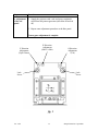
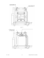
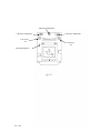
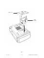
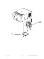
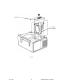
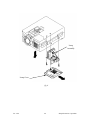
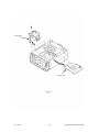
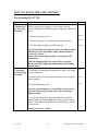
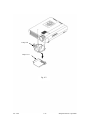
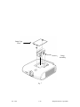
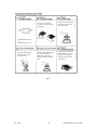
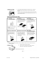
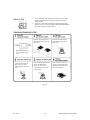
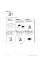
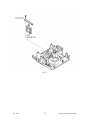
Addendum to the Sharp Limited Servicer Maintenance Manual
Including models:
PG-D100U
XG-E1200U
XG-E3000U
XG-E3500U
XG-NV1U
XG-NV2U
XG-NV3XU
XG-NV3XB
XG-NV4SU
XG-NV5XU
XG-NV6XU
XG-NV7XU
XV-C10U
XV-C10U(P)
XV-H37VUA
Ver. 3/00 Volume 1
Table of Contents
Subject
Convergence
PG-D100U, XG-E1200U, XG-E3000U,
XG-E3500U, XG-NV1U, XG-NV2U,
XG-NV3XU, XG-NV3XB
XG-NV4SU, XG-NV5XU
XG-NV6XU
Page
1-1
1-4
1-7
Lamp Replacement
PG-D100U, XG-NV1U
XG-E1200U, XG-E3000U, XG-E3500U
XG-NV2U, XG-NV3XU, XG-NV3XB
XG-NV4SU, XG-NV5XU
XG-NV6XU
XG-NV7XU
XV-C10U, XV-C10U(P)
2-1
2-3
2-5
2-7
2-9
2-11
2-13
Filter / Cleaning / Replacement
PG-D100U, XG-NV1U
XG-E1200U, XG-E3000U, XG-E3500U
XG-NV2U, XG-NV3XU, XG-NV3XB
XG-NV4SU, XG-NV5XU, XG-NV6XU
XV-C10U, XV-C10U(P)
3-1
3-3
3-5
3-7
3-9
Cleaning the LCD Panels
XV-C10U, XV-C10UP
Note: Because of the difficulty of removing the LCD panels, cleaning the
LCD panels is beyond the scope of the Limited Servicer Program for all
other models included in this addendum.
4-1
Notes:
1. The safety and various description sections must be read in the Main Limited
Servicer Maintenance Manual (part code SM-LCD) before attempting any
procedures outlined in this addendum.
2. The maintenance procedures for the XV-H37VUA, XV-H37VUA(P) are
identical to the XG-E1100U. Therefore, please refer to the Main Limited
Servicer Maintenance Manual when maintaining the XV-H37VUA.
Ver. 3/00 Volume 1
HOW TO CONVERGE THE LCD PANELS
For the models XG-NV1U, XG-E1200U, PG-D100U, XG-E3000U,
XG-NV2U, XG-NV3XU, XG-NV3XB, and XG-E3500U
Tools and equipment needed:
• Pattern Generator that can produce a crosshatch pattern (grid pattern)
• Eccentric Cam Adjustment Wrench. (Sharp Part # 9DASPN-XGNV1U)
• L-shaped Hex Wrench (Sharp part # 9EQLNC-XGNV1U)
• Philips Screwdriver
NOTE: Confirm focus before performing the convergence procedure. If pixels are
in focus in one area of the screen and indistinguishable in another area, the
projector is out of focus. The focus alignment procedure is beyond the scope of the
limited maintenance program.
Step
Procedure
Ref. #
1. Checking
convergence.
Refer to the safety notes on page S-1 of the Main Limited
Servicer Maintenance Manual before attempting to converge
the panels.
1. Connect a pattern generator to the video or RGB (when
applicable ) input terminals.
2. Output a crosshatch signal from the pattern generator.
3. Turn on the projector.
fig. 3-4
4. Mentally divide the screen into fourths both horizontally
(Main
and vertically. Imagine the center four squares as the A zone Manual)
and the outer one fourth (all around the outside edge) as the B
zone. Look at the grids to determine if the convergence is off.
You should see only white grid lines on the screen ( a white
line is the product of separate red, green, and blue lines
“added together,” or converged over the same area ). If the
red or blue lines are offset from the green lines ( either
up/down or left/right ), the convergence is off. The green
panel is fixed, so mechanical adjustment isn’t possible. If
any adjustments to the red or blue panels are necessary,
use green as the reference. If the unit is converged to within
one pixel in the A zone and one and a half pixels in the B
zone the unit is converged within specification and adjustment
is not required.
Continued on next page
Ver. 3/00
1-1
Sharp Electronics Corporation
HOW TO CONVERGE THE LCD PANELS (continued)
Step
Procedure
Ref. #
2. Removal of
body panels.
1. To remove the cabinet, refer to the service manual for the
specific model.
3. Adjustment
of the blue
panel.
1. Supply the projector with a blue and green crosshatch
signal from the pattern generator (on most video signal
generators, it is possible to remove one or more of the 3
colors making up the crosshatch signal. In this case red
must be removed. To do this refer to the instructions for
the pattern generator).
2. Use the L-shaped hex wrench to loosen the two hex screws
labeled “Lock Screw” in fig. 1.
Be sure to leave the lock screws tight enough so that when
an adjustment is made, the panel will stay in that position
until the lock screws are fully tightened after the
completion of all adjustments.
fig. 1
3. Use the eccentric cam wrench to adjust the Y axis (up and
down).
fig. 1
4. Use the eccentric cam wrench to adjust the X axis (side to
side).
fig. 1
5. Use the eccentric cam wrench to adjust the θZ axis
(tilt).
fig. 1
6. When the blue image is converged within specifications to
the green panel, tighten the two lock screws to secure the
adjustments.
fig. 1
NOTE: Tightening the screws may cause mis-convergence.
If this happens, readjust the affected panel.
Ver. 3/00
1-2
Sharp Electronics Corporation
Step
Procedure
4. Adjustment
of the red
panel
1. Supply the projector with a red and green crosshatch
signal from the pattern generator (turn blue off and red
on).
2. Repeat same adjustment procedure as the blue panel.
Convergence adjustment is complete.
Y Direction
Adjustment
(Up & Down)
X Direction
Adjustment
(Side To Side)
Lock
Screw
θ Direction
Adjustment
(Tilt)
Lock
Screw
fig. 1
Ver. 3/00
1-3
Sharp Electronics Corporation
HOW TO CONVERGE THE LCD PANELS
For the models XG-NV4SU and XG-NV5XU
Tools and equipment needed:
•
•
•
•
•
Pattern Generator that can produce a crosshatch pattern (grid pattern)
Eccentric Cam Adjustment Wrench. (Sharp Part # 9DASPN-XGNV1U)
2mm Hex Wrench (Sharp part # 9EQLNC-XGNV4U)
1.27mm Hex Wrench (available at most hardware stores)
Philips Screwdriver
NOTE: Confirm focus before convergence procedure. If pixels are in focus in one
area of the screen and indistinguishable in another area, the projector is out of
focus. The focus alignment procedure is beyond the scope of the limited
maintenance program.
Step
Procedure
Ref. #
1. Checking
convergence.
Refer to the safety notes on page S-1 of the Main Limited
Servicer Maintenance Manual before attempting to converge
the panels.
1. Connect a pattern generator to the video or RGB (when
applicable ) input terminals.
2. Output a crosshatch signal from the pattern generator.
3. Turn on the projector.
fig. 3-4
4. Mentally divide the screen into fourths both horizontally
(Main
and vertically. Imagine the center four squares as the A zone Manual)
and the outer one fourth (all around the outside edge) as the B
zone. Look at the grids to determine if the convergence is off.
You should see only white grid lines on the screen ( a white
line is the product of separate red, green, and blue lines
“added together”, or converged over the same area ). If the
red or blue lines are offset from the green lines ( either
up/down or left/right ), the convergence is off. The green
panel is fixed, so mechanical adjustment isn’t possible. If
any adjustments to the red or blue panels are necessary,
use green as the reference. If the unit is converged to within
one pixel in the A zone and one and a half pixels in the B
zone the unit is converged within specification and adjustment
is not required.
Continued on next page.
Ver. 3/00
1-4
Sharp Electronics Corporation
HOW TO CONVERGE THE LCD PANELS (continued)
Step
Procedure
Ref. #
2. Removal of
body panels.
1. To remove the cabinet, refer to the service manual for the
specific model.
3. Adjustment
of the blue
panel.
1. Supply the projector with a blue and green crosshatch signal
from the pattern generator (on most video signal generators, it
is possible to remove one or more of the 3 colors making up the
crosshatch signal. In this case red must be removed. To do this,
refer to the instructions for the pattern generator).
2. Use the 2mm Hex Wrench to loosen the two hex screws labeled
“Lock Screw d” in fig. 2.
Be sure to leave the lock screws tight enough so that when an
adjustment is made, the panel will stay in that position
until the lock screws are fully tightened after the
completion of all adjustments.
fig. 2-1
3. Use the 1.27mm hex wrench to adjust the Y axis (up and
down).
fig. 2-1
4. Use the eccentric cam wrench to adjust the X axis (side to
side).
fig. 2-2
5. Use the 1.27mm hex wrench to adjust the θZ axis
(tilt).
fig. 2-2
6. When the blue image is converged within specifications to
the green panel, tighten the two lock screws to secure the
adjustments.
fig. 2-2
NOTE: Tightening the screws may cause mis-convergence.
If this happens, readjust the affected panel.
4. Adjustment
of the red panel
1. Supply the projector with a red and green crosshatch signal
from the pattern generator (turn blue off and red on).
2. Repeat same adjustment procedure as the blue panel.
Convergence adjustment is complete.
Ver. 3/00
1-5
Sharp Electronics Corporation
fig. 2-1
Y Direction Adj.
(1.27mm Hex)
fig. 2-2
Ver. 3/00
1-6
Sharp Electronics Corporation
HOW TO CONVERGE THE LCD PANELS
For the model XG-NV6XU
Tools and equipment needed:
•
•
•
•
•
Pattern Generator that can produce a crosshatch pattern (grid pattern)
Eccentric Cam Adjustment Wrench. (Sharp Part # 9DASPN-XGNV1U)
2mm Hex Wrench (Sharp part # 9EQLNC-XGNV1U)
1.27mm Hex Wrench (available at most hardware stores)
Philips Screwdriver
NOTE: Confirm focus before convergence procedure. If pixels are in focus in one
area of the screen and indistinguishable in another area, the projector is out of
focus. The focus alignment procedure is beyond the scope of the limited
maintenance program.
Step
Procedure
Ref. #
1. Checking
convergence.
Refer to the safety notes on page S-1 of the Main Limited
Servicer Maintenance Manual before attempting to converge
the panels.
1. Connect a pattern generator to the video or RGB (when
applicable ) input terminals.
2. Output a crosshatch signal from the pattern generator.
3. Turn on the projector.
fig. 3-4
4. Mentally divide the screen into fourths both horizontally
(Main
and vertically. Imagine the center four squares as the A zone Manual)
and the outer one fourth (all around the outside edge) as the B
zone. Look at the grids to determine if the convergence is off.
You should see only white grid lines on the screen ( a white
line is the product of separate red, green, and blue lines
“added together”, or converged over the same area ). If the
red or blue lines are offset from the green lines ( either
up/down or left/right ), the convergence is off. Do not adjust
the green panel. The green panel is fixed, so mechanical
adjustment isn’t possible. If any adjustments to the red or
blue panels are necessary, use green as the reference. If the
unit is converged to within one pixel in the A zone and one
and a half pixels in the B zone the unit is converged within
specification and adjustment is not required.
Ver. 3/00
1-7
Sharp Electronics Corporation
Continued on next page.
HOW TO CONVERGE THE LCD PANELS (continued)
Step
Procedure
Ref. #
2. Removal of
body panels.
1. To remove the cabinet, refer to the service manual for the
specific model.
3. Adjustment
of the blue
panel.
1. Supply the projector with a blue and green crosshatch signal
from the pattern generator (on most video signal generators, it
is possible to remove one or more of the 3 colors making up the
crosshatch signal. In this case red must be removed. To do this,
refer to the instructions for the pattern generator).
2. Use the 2mm hex wrench to loosen the two hex screws labeled
“Lock Screw d” in fig. 2.
Be sure to leave the lock screws tight enough so that when an
adjustment is made, the panel will stay in that position
until the lock screws are fully tightened after the
completion of all adjustments.
fig. 2-3
1. Use the eccentric cam wrench to adjust the Y axis (up and
down).
fig. 2-3
3. Use the eccentric cam wrench to adjust the X axis (side to
side).
fig. 2-3
4. Use the eccentric cam wrench to adjust the θZ axis
(tilt).
fig. 2-3
5. When the blue image is converged within specifications to
the green panel, tighten the two lock screws to secure the
adjustments.
fig. 2-3
NOTE: Tightening the screws may cause mis-convergence.
If this happens, readjust the affected panel.
4. Adjustment
of the red panel
1. Supply the projector with a red and green crosshatch signal
from the pattern generator (turn blue off and red on).
2. Repeat same adjustment procedure as the blue panel.
Convergence adjustment is complete.
Ver. 3/00
1-8
Sharp Electronics Corporation
X Direction Adjustment
Y Direction Adjustment
θ Direction Adjustment
Lock Screw
"D"
Lock Screw
"D"
R,B Adjusting Plate
fig. 2-3
Ver. 3/00
1-9
Sharp Electronics Corporation
HOW TO CHANGE THE LAMP ASSEMBLY
For The Models PG-D100U and XG-NV1U
Step
Procedure
Ref. #
1. Removal of
the old Lamp
Assembly.
Refer to safety notes on page S-1 in the Main Limited
Servicer Maintenance Manual before attempting to change the
lamp
1. Remove the lamp cover.
fig. 3
2. Remove the screws securing the lamp assembly.
fig. 3
3. Pull the lamp assembly out of the projector.
fig. 3
Safety notes: Be sure to wear Safety Glasses when
removing the lamp. Do not attempt to remove the lamp
assembly until the projector has had an ample amount of
time to cool down.( 1 hour. )
After removing the lamp assembly, do not look at the
actual lamp.
Place the lamp assembly face down. This is necessary
because the metal halide lamp is pressurized and could
explode causing injury.
2. Installing
the new Lamp
Assembly.
1. Insert the new assembly by pushing on it until it fits snugly
into the Lamp Well.
fig 3
2. Install the screws into the same holes as the original lamp
assembly.
fig 3
3. Re-install the lamp cover.
fig 3
Note: Be sure the lamp cover is installed correctly or the
projector will not operate due to the safety switch not
being activated.
4. To reset the lamp timer, press and hold down the Enter,
Adjust Down, and Adjust Right Keys, then apply power to the
unit with the Main Power Switch on the side of the projector.
The projector should power on and display “0000H” on the
screen.
Lamp replacement is complete.
Ver. 3/00
2-1
Sharp Electronics Corporation
Lamp Cover
Lamp
Assembly
fig. 3
Ver. 3/00
2-2
Sharp Electronics Corporation
HOW TO CHANGE THE LAMP ASSEMBLY
For the models XG-E1200U, XG-E3000U, and XG-E3500U
Step
Procedure
Ref. #
1. Removal of
the old Lamp
Assembly.
Refer to safety notes on page S-1 in the Main Limited
Servicer Maintenance Manual before attempting to change the
lamp
1. Remove the lamp cover.
fig. 4
2. Remove the screws securing the lamp assembly.
fig. 4
3. Pull the lamp assembly out of the projector.
fig. 4
Safety notes: Be sure to wear Safety Glasses when
removing the lamp. Do not attempt to remove the lamp
assembly until the projector has had an ample amount of
time to cool down.( 1 hour. )
After removing the lamp assembly, do not look at the
actual lamp.
Place the lamp assembly face down. This is necessary
because the metal halide lamp is pressurized and could
explode causing injury.
2. Installing
the new Lamp
Assembly.
1. Insert the new assembly by pushing on it until it fits snugly
into the lamp well.
Fig 4
2. Install the screws into the same holes as the original lamp
assembly.
Fig 4
3. Re-install the lamp cover.
Fig 4
Note: Be sure the lamp cover is installed correctly or the
projector will not operate due to the safety switch not
being activated.
3. To reset the lamp timer, press and hold down the Enter,
Adjust Down, and Adjust Right Keys, then apply power to the
unit with the Main Power Switch on the side of the projector.
The projector should power on and display “0000H” on the
screen.
Lamp replacement is complete.
Ver. 3/00
2-3
Sharp Electronics Corporation
Lamp
Assembly
Lamp
Cover
fig. 4
Ver. 3/00
2-4
Sharp Electronics Corporation
HOW TO CHANGE THE LAMP ASSEMBLY
For the models XG-NV2U, XG-NV3XU, and XG-NV3XB
Step
Procedure
Ref. #
1. Removal of
the old Lamp
Assembly.
Refer to safety notes on page S-1 in the Main Limited
Servicer Maintenance Manual before attempting to change the
lamp
1. Remove the lamp cover.
fig. 5
2. Remove the screws securing the lamp assembly.
fig. 5
3. Pull the lamp assembly out of the projector.
fig. 5
Safety notes: Be sure to wear Safety Glasses when
removing the lamp. Do not attempt to remove the lamp
assembly until the projector has had an ample amount of
time to cool down.( 1 hour. )
After removing the lamp assembly, do not look at the
actual lamp.
Place the lamp assembly face down. This is necessary
because the UHP Lamp is pressurized and could explode
causing injury.
2. Installing
the new Lamp
Assembly.
1. Insert the new assembly by pushing on it until it fits snugly
into the lamp well.
Fig 5
2. Install the screws into the same holes as the original lamp
assembly.
Fig 5
Fig 5
3. Re-install the lamp cover.
Note: Be sure the lamp cover is installed correctly or the
projector will not operate due to the safety switch not
being activated.
3. To reset the lamp timer, press and hold down the Enter,
Adjust Down, and Adjust Right Keys, then apply power to the
unit with the Main Power Switch on the rear of the projector.
The projector should power on and display “0000H” on the
screen.
Lamp replacement is complete.
Ver. 3/00
2-5
Sharp Electronics Corporation
Lamp Cover
Lamp
Assembly
fig. 5
Ver. 3/00
2-6
Sharp Electronics Corporation
HOW TO CHANGE THE LAMP ASSEMBLY
For the models XG-NV4SU and XG-NV5XU
Step
Procedure
Ref. #
1. Removal of
the old Lamp
Assembly.
Refer to safety notes on page S-1 in the Main Limited
Servicer Maintenance Manual before attempting to change the
lamp
fig. 6
1. Remove the lamp cover.
2. Remove the screws securing the lamp assembly.
3. Pull the lamp assembly out of the projector.
fig. 6
fig. 6
Safety notes: Be sure to wear Safety Glasses when
removing the lamp. Do not attempt to remove the lamp
assembly until the projector has had an ample amount of
time to cool down.( 1 hour. )
After removing the lamp assembly, do not look at the
actual lamp.
Place the lamp assembly face down. This is necessary
because the UHP lamp is pressurized and could explode
causing injury.
2. Installing
the new Lamp
Assembly.
1. Insert the new assembly by pushing on it until it fits snugly
into the lamp well.
fig 6
2. Install the screws into the same holes as the original lamp
assembly.
fig 6
fig 6
3. Re-install the lamp cover.
Note: Be sure the lamp cover is installed correctly or the
projector will not operate due to the safety switch not
being activated.
3. To reset the lamp timer, press and hold down the Enter,
Adjust Down, and Adjust Right Keys, then apply power to the
unit with the Main Power Switch on the rear of the projector.
The projector should power on and display “0000H” on the
screen.
Lamp replacement is complete.
Ver. 3/00
2-7
Sharp Electronics Corporation
fig. 6
Lamp
Assembly
Lamp Cover
fig. 6
Ver. 3/00
2-8
Sharp Electronics Corporation
HOW TO CHANGE THE LAMP ASSEMBLY
For the model XG-NV6XU
Step
Procedure
Ref. #
1. Removal of
the old lamp
assembly.
Refer to safety notes on page S-1 in the Main Limited
Servicer Maintenance Manual before attempting to change the
lamp
fig. 6-1
1. Remove the lamp cover.
2. Remove the three screws securing the lamp assembly.
3. Pull the lamp assembly out of the projector.
fig. 6-1
fig. 6-1
Safety notes: Be sure to wear Safety Glasses when
removing the lamp. Do not attempt to remove the lamp
assembly until the projector has had an ample amount of
time to cool down.( 1 hour. )
After removing the lamp assembly, do not look at the
actual lamp.
Place the lamp assembly face down. This is necessary
because the UHP lamp is pressurized and could explode
causing injury.
2. Installing
the new lamp
assembly.
1. Insert the new assembly by pushing on it until it fits snugly
into the lamp well.
fig 6-1
2. Install the three screws into the same holes as the original
lamp assembly.
fig 6-1
fig 6-1
3. Re-install the lamp cover.
Note: Be sure the lamp cover is installed correctly or the
projector will not operate due to the safety switch not
being activated.
3. To reset the lamp timer, press and hold down the Enter,
Adjust Down, and Adjust Right Keys, then press the Power
On Key. The projector should power on and display “0000H”
on the screen.
Lamp replacement is complete.
Ver. 3/00
2-9
Sharp Electronics Corporation
Lamp Unit
Fig. 6
Lamp Cover
fig. 6-1
Ver. 3/00
2-10
Sharp Electronics Corporation
HOW TO CHANGE THE LAMP ASSEMBLY
For the model XG-NV7XU
Step
Procedure
Ref. #
1. Removal of
the old Lamp
Assembly.
Refer to safety notes on page S-1 in the Main Limited
Servicer Maintenance Manual before attempting to change the
lamp
fig. 6-2
1. Remove the Lamp Cover.
2. Remove the three screws securing the lamp assembly.
3. Pull the lamp assembly out of the projector.
fig. 6-2
fig. 6-2
Safety notes: Do not attempt to remove the lamp assembly
until the projector has had an ample amount of time to
cool down.( 1 hour. )
After removing the lamp assembly, do not look at the
actual lamp.
Place the lamp assembly face down. This is necessary
because the UHP lamp is pressurized and could explode
causing injury.
2. Installing
the new Lamp
Assembly.
1. Insert the new assembly by pushing on it until it fits snugly
into the lamp well.
fig 6-2
2. Install the three screws into the same holes as the original
lamp assembly.
fig 6-2
fig 6-2
3. Re-install the lamp cover.
Note: Be sure the lamp cover is installed correctly or the
projector will not operate due to the safety switch not
being activated.
3. To reset the lamp timer, press and hold down the Enter,
Adjust Down, and Adjust Right Keys, then press the Power
On Key. The projector should power on and display “0000H”
on the screen.
Lamp replacement is complete.
Ver. 3/00
2-11
Sharp Electronics Corporation
Lamp Unit
Lamp Cover
fig. 6-2
Fig. 6-1
Ver. 3/00
2-12
Sharp Electronics Corporation
HOW TO CHANGE THE LAMP ASSEMBLY
For the model XV-C10U and XV-C10U(P)
Step
Procedure
Ref. #
1. Removal of
the old Lamp
Assembly.
Refer to safety notes on page S-1 in the Main Limited
Servicer Maintenance Manual before attempting to change the
lamp
1. Remove the lamp cover.
fig. 7
2. Remove the two screws securing the lamp assembly.
fig. 7
3. Pull the lamp assembly out of the projector.
fig. 7
Safety notes: Be sure to wear Safety Glasses when
removing the lamp. Do not attempt to remove the lamp
assembly until the projector has had an ample amount of
time to cool down.( 1 hour. )
After removing the lamp assembly, do not look at the
actual lamp.
Place the lamp assembly face down. This is necessary
because the metal halide lamp is pressurized and could
explode causing injury.
2. Installing
the new Lamp
Assembly.
1. Insert the new assembly by pushing on it until it fits snugly
into the lamp well.
fig. 7
fig. 7
2. Install the screws into the same holes as the original lamp
assembly.
fig. 7
3. Re-install the lamp cover.
Note: Be sure the lamp cover is installed correctly or the
projector will not operate due to the safety switch not
being activated.
3. To reset the lamp timer, press and hold down the Enter,
Adjust Down, and Adjust Right Keys, then apply power to the
unit with the Main Power Switch on the side of the projector.
The projector should power on and display “0000H” on the
screen.
Lamp replacement is complete.
Ver. 3/00
2-13
Sharp Electronics Corporation
Lamp Cage
Cover
Lamp
Assembly
fig. 7
Ver. 3/00
2-14
Sharp Electronics Corporation
HOW TO CLEAN OR REPLACE AIR FILTER
For the Models PG-D100U and XG-NV1U
Step
Procedure
Ref. #
1. Removal of
the Filter
Cover.
1. To remove the fan cover, refer to the service manual for the
specific model. The fan cover will either slide out or snap into
place from the unit.
2. Removal of
the Filter.
1. Separate the plastic filter cover from the fan cover by
slightly flexing the fixed retaining tabs away from the inner
perimeter of the fan cover, remove filter.
3. Inspecting
the Filter.
1. Inspect the filter for signs of dirt and debris.
fig. 8
fig. 8
2. Hold the filter to the light and ensure that some light passes
through the filter. If some light passes, continue to step 4. If
all light is restricted, proceed to step 5.
4. Cleaning
the Filter.
1. To clean the filter, vacuum it with a brush attachment.
fig. 8
Note: Do not just brush the filter, as particles of debris
will just be worked into the filter deeper.
5. Replacing
the Filter.
1. If the filter has been subjected to a harsh environment that
caused the filter to become sticky or embedded with particles
that cannot be removed with a vacuum, replace it.
fig. 8
2. Install the new or cleaned filter into the fan cover, re-attach
the filter cover, and re-connect the fan cover to the projector.
Note: The filter must be properly replaced before the
projector can be operated. A safety switch is mounted in
the projector. It is activated by the filter or the fan cover.
If the switch is not activated, the lamp will not light.
Filter replacement is complete.
Ver. 3/00
3-1
Sharp Electronics Corporation
Press the arrow mark on
the air filter cover and pull
straight out.
Grasp the air filter between
your fingers and lift it out
of the filter cover.
POWER indicator goes
off.
Unplug the power cord.
Clean the dust off the air
filter and cover with a
vacuum cleaner.
Place the filter underneath the
tabs on the filter frame.
Return the air filter to its
original position in the filter
cover.
Insert the two tabs on the
end of the filter cover into
the filter cover opening
and press the filter cover
into position.
fig. 8
Ver. 3/00
3-2
Sharp Electronics Corporation
HOW TO CLEAN OR REPLACE AIR FILTER
For the Models XG-E1200U, XG-E3000U, and XG-E3500U
Step
Procedure
Ref. #
1. Removal of
the Filter
Cover.
1. To remove the fan cover, refer to the service manual for the
specific model. The fan cover will either slide out or snap into
place from the unit.
2. Removal of
the Filter.
1. Separate the plastic filter cover from the fan cover by
slightly flexing the fixed retaining tabs away from the inner
perimeter of the fan cover, remove filter.
3. Inspecting
the Filter.
1. Inspect the filter for signs of dirt and debris.
fig. 9
fig. 9
fig. 9
2. Hold the filter to the light and ensure that some light passes
through the filter. If some light passes, continue to step 4. If
all light is restricted, proceed to step 5.
4. Cleaning
the Filter.
1. To clean the filter, vacuum it with a brush attachment.
fig. 9
Note: Do not just brush the filter, as particles of debris
will just be worked into the filter deeper.
5. Replacing
the Filter.
1. If the filter has been subjected to a harsh environment that
caused the filter to become sticky or embedded with particles
that cannot be removed with a vacuum, replace it.
fig. 9
2. Install the new or cleaned filter into the fan cover, re-attach
the filter cover, and re-connect the fan cover to the projector.
Note: The filter must be properly replaced before the
projector can be operated. A safety switch is mounted in
the projector. It is activated by the filter or the fan cover.
If the switch is not activated, the lamp will not light.
Filter replacement is complete.
Ver. 3/00
3-3
Sharp Electronics Corporation
• The air filter should be cleaned every 100 hours of use. Clean the
filter more often when the projector is used in a dusty or smoky
location.
• Have your nearest Authorized Sharp Industrial LCD Products Dealer
or Service Center exchange the filter (PFILD0055CEZZ) when it is no
longer possible to clean it.
Press the tab in the direction
of the arrow and lift open
the filter cover.
Grasp the air filter between
your fingers and lift it out of
the filter cover.
Turn off the MAIN POWER
switch.
POWER indicator goes off.
Unplug the power cord.
Clean the dust off the air
filter and cover with a
vacuum cleaner extension
hose.
Place the filter underneath
the tabs on the filter frame.
Return the air filter to its
original position in the filter
cover opening.
Insert the tab on the end of
the filter cover into the filter
cover opening and press the
filter cover into position.
NOTE:
• Be sure the AIR FILTER COVER is securely installed. The power cannot be turned on unless it is
correctly installed.
• The side air filter cannot be removed.
• If dust or dirt has collected inside the filter, clean the
filter with a vacuum cleaner extension hose.
AIR FILTER (Not removable)
fig. 9
Ver. 3/00
3-4
Sharp Electronics Corporation
HOW TO CLEAN OR REPLACE AIR FILTER
For the Models XG-NV2U, XG-NV3XU, and XG-NV3XB
Step
Procedure
Ref. #
1. Removal of
the Filter
Cover.
1. To remove the fan cover, refer to the service manual for the
specific model. The fan cover will either slide out or snap into
place from the unit.
2. Removal of
the Filter.
1. Separate the plastic filter cover from the fan cover by
slightly flexing the fixed retaining tabs away from the inner
perimeter of the fan cover, remove filter.
3. Inspecting
the Filter.
1. Inspect the filter for signs of dirt and debris.
fig. 10
fig. 10
fig. 10
2. Hold the filter to the light and ensure that some light passes
through the filter. If some light passes, continue to step 4. If
all light is restricted, proceed to step 5.
4. Cleaning
the Filter.
1. To clean the filter, vacuum it with a brush attachment.
fig. 10
Note: Do not just brush the filter, as particles of debris
will just be worked into the filter deeper.
5. Replacing
the Filter.
1. If the filter has been subjected to a harsh environment that
caused the filter to become sticky or embedded with particles
that cannot be removed with a vacuum, replace it.
fig. 10
2. Install the new or cleaned filter into the fan cover, re-attach
the filter cover, and re-connect the fan cover to the projector.
Note: The filter must be properly replaced before the
projector can be operated. A safety switch is mounted in
the projector. It is activated by the filter or the fan cover.
If the switch is not activated, the lamp will not light.
Filter replacement is complete.
Ver. 3/00
3-5
Sharp Electronics Corporation
• The air filter should be cleaned every 100 hours of use. Clean
the filter more often when the projector is used in a dusty or
smoky location.
• Have your nearest Authorized Sharp Industrial LCD Products
Dealer or Service Center exchange the filter (PFILD0059CEZZ)
when it is no longer possible to clean it.
Press the tab in the direction
of the arrow and lift open the
filter cover.
Grasp the air filter between
your fingers and lift out the
filter cover.
Place the filter underneath the
tabs on the filter frame.
Return the air filter to its
original position in the filter
cover opening.
Insert the tab on the end of
the cover into the filter cover
opening and press the filter
cover into position.
POWER indicator goes
off. Unplug the power
cord.
Clean the dust off the air
filter and cover with a
vacuum cleaner extension
hose.
fig. 10
Ver. 3/00
3-6
Sharp Electronics Corporation
HOW TO CLEAN OR REPLACE AIR FILTER
For the Models XG-NV4SU, XG-NV5XU and XG-NV6XU
Step
Procedure
Ref. #
1. Removal of
the Filter
Cover.
1. To remove the fan cover, refer to the service manual for the
specific model. The fan cover will either slide out or snap into
place from the unit.
2. Removal of
the Filter.
1. Separate the plastic filter cover from the fan cover by
slightly flexing the fixed retaining tabs away from the inner
perimeter of the fan cover, remove filter.
3. Inspecting
the Filter.
1. Inspect the filter for signs of dirt and debris.
fig. 11
fig. 11
fig. 11
2. Hold the filter to the light and ensure that some light passes
through the filter. If some light passes, continue to step 4. If
all light is restricted, proceed to step 5.
4. Cleaning
the Filter.
1. To clean the filter, vacuum it with a brush attachment.
fig. 11
Note: Do not just brush the filter, as particles of debris
will just be worked into the filter deeper.
5. Replacing
the Filter.
1. If the filter has been subjected to a harsh environment that
caused the filter to become sticky or embedded with particles
that cannot be removed with a vacuum, replace it.
fig. 11
2. Install the new or cleaned filter into the fan cover, re-attach
the filter cover, and re-connect the fan cover to the projector.
Note: The filter must be properly replaced before the
projector can be operated. A safety switch is mounted in
the projector. It is activated by the filter or the fan cover.
If the switch is not activated, the lamp will not light.
Filter replacement is complete.
Ver. 3/00
3-7
Sharp Electronics Corporation
Press the tab in the direction
of the arrow and lift open the
filter cover.
Grasp the air filter between
your fingers and lift out the
filter cover.
Place the filter underneath the
tabs on the filter frame.
Return the air filter to its
original position in the filter
cover opening.
Insert the tab on the end of
the cover into the filter cover
opening and press the filter
cover into position.
POWER indicator goes
off. Unplug the power
cord.
Clean the dust off the air
filter and cover with a
vacuum cleaner extension
hose.
fig. 11
Ver. 3/00
3-8
Sharp Electronics Corporation
HOW TO CLEAN OR REPLACE AIR FILTER
For the Model XV-C10U and XV-C10U(P)
Step
Procedure
Ref. #
1. Removal of
the Filter
Cover.
1. To remove the fan cover, refer to the service manual for the
specific model. The fan cover will either slide out or snap into
place from the unit.
2. Removal of
the Filter.
1. Separate the plastic filter cover from the fan cover by
slightly flexing the fixed retaining tabs away from the inner
perimeter of the fan cover, remove filter.
3. Inspecting
the Filter.
1. Inspect the filter for signs of dirt and debris.
fig. 12
fig. 12
fig. 12
2. Hold the filter to the light and ensure that some light passes
through the filter. If some light passes, continue to step 4. If
all light is restricted, proceed to step 5.
4. Cleaning
the Filter.
1. To clean the filter, vacuum it with a brush attachment.
fig. 12
Note: Do not just brush the filter, as particles of debris
will just be worked into the filter deeper.
5. Replacing
the Filter.
1. If the Filter has been subjected to a harsh environment that
caused the filter to become sticky or embedded with particles
that cannot be removed with a vacuum, replace it.
fig. 12
2. Install the new or cleaned filter into the fan cover, re-attach
the filter cover, and re-connect the fan cover to the projector.
Note: The filter must be properly replaced before the
projector can be operated. A safety switch is mounted in
the projector. It is activated by the filter or the fan cover.
If the switch is not activated, the lamp will not light.
Filter replacement is complete.
Ver. 3/00
3-9
Sharp Electronics Corporation
Remove Filter
From Fan
Cover & And
Clean
Fan
Cover
fig. 12
Ver. 3/00
3-10
Sharp Electronics Corporation
HOW TO CLEAN THE LCD PANELS
For the Model XV-C10U
Tools and equipment needed:
• Philips screw driver
• Dry lens cleaning tissue, bleached cotton cloth, or lens brush
Step
1. Removing
the necessary
Body Panels.
Procedure
Refer to safety notes on page S-1 in the Main Limited
Servicer Maintenance Manual before attempting to clean the
panels.
Ref. #
1. To remove the Body Panel, first remove the Upper Cabinet
Body to gain access to the components. ( Refer to the specific
service manual.)
2. Removing
the LCD
Panel
1. Remove wire connector (LD) from the control unit.
2. Remove the panel cover screw.
fig. 13
Remove the LCD panel by pulling the Panel slowly upward.
3. Clean the
LCD Panel.
1. Use a dry cotton based lens cleaning tissue, bleached cotton
cloth, or lens brush to dab any large pieces of dust or debris
from the LCD panel
Note: Do not use any cleaning solutions as they may
damage the panel. Dust is easily removed with a dry lens
cleaning tissue, bleached cotton cloth, or lens brush.
4. Reassemble
1. Reinstall the LCD Panel Assembly into the projector,
securing the screw.
fig. 13
2. After the panel is cleaned always check the results
immediately after the procedure. Any time the panel is
exposed, it may pickup additional dust or debris. To check
the results, input the appropriate raster signal ( an all red,
green, or blue signal ) from a signal generator to the video
or RGB input. Inspect the projected image for any more
dust or debris. If dust is present, repeat steps 2 and 3. If
this procedure is done in a dusty environment, it may take
a few cleanings before a dust free image is present.
End of procedure.
Ver. 3/00
4-1
Sharp Electronics Corporation
fig. 13
Ver. 3/00
4-2
Sharp Electronics Corporation