1
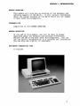
EPSON QX-10 MICROCOMPUTER SYSTEM
TRAINING PROGRAM
DECEMBER 1983
SBXEBT030
Published by:
Xerox Corporation, Rochester, New York
14644
Prepared by:
Multinational Documentation and Training Services
Xerox Corporation, Rochester, New York 14644
Copyright 1983 by Xerox Corporation. All rights reserved.
XEROX is a trademark of Xerox Corporation
QX-IO is a registered trademark of Epson America, Inc.
TABLE OF CONTENTS
PROGRAM OVERVIEW ••••••••••••••••••••••••••
Module 1, Introduction •••••••••••••••
Module 2, Installation and Operation.
Module 3, Service Documentation.
Module 4, Troubleshooting ••
Prerequisites ••••••••••••••
Program Objectives •••••••••
Estimated Completion Time ••
Required Resources •••
Program Instructions •••••••
1
1
1
1
1
MODULE 1, INTRODUCTION ••
Module Overview ••
Prerequisites ••••••
Module Objective •••
Estimated Completion Time ••
Self-Test 'I ••
Feedback #1 ••
3
3
3
3
3
5
MODULE 2, INSTALLATION AND OPERATION ••
Module Overview ••
Prerequisite •••••••••••••••
Module Objective •••••••••••
Estimated Completion Time ••
Self-Test 12 •••••••
Feedback #2 ••
2
2
2
2
2
6
7
7
7
7
7
9
• .10
MODULE 3, SERVICE DOCUMENTATION.
Module Overview ••
Prerequisite •••••••••••••••
Module Objective •••••••••••
Estimated Completion Time ••
Self-Test f3 ••
Feedback #3 •••
• .14
MODULE 4, TROUBLESHOOTING.
Module Overview ••
Prerequisite •••••••••
Module Objective •••••
Estimated Completion Time ••
Submodule 1 ••
Submodule 2 ••
Submodule 3 ••
Submodule 4 ••
Self-Test #4 ••
Feedback 14 •••
.15
.15
.15
. .... .. 15
.15
.16
.17
.18
.19
..20
..21
1
.11
.11
.11
.11
.11
.13
PROGRAM OVERVIEW
This training program will prepare you to service the Epson QX-IO
microcomputer system. You will learn how to use the service
documentation for troubleshooting, removal and replacement of
parts and adjustments. This program is divided into the
following modules.
MODULE 1
INTRODUCTION
This module gives an overview of the hardware and
software aspects of the QX-IO. It will contain
information about the unique features of the QX-IO
which are not common to most other microcomputers.
MODULE 2
INSTALLATION & OPERATION
In this module, you will learn to install and verify
the basic operation of the microcomputer.
MODULE 3
SERVICE DOCUMENTATION
This module discusses the Epson QX-IO technical
manuals and introduces you to the service
documentation.
MODULE 4
TROUBLESHOOTING
In this module, you will learn how to use the
documentation to troubleshoot down to the smallest
assembly shown in the parts lists with a Xerox part
number.
1
PROGRAM OVERVIEW
PREREQUISITES
You must have successfully completed the generic training
program for microcomputers.
PROGRAM OBJECTIVES
You will be able to state, in writing, what troubleshooting
techniques, repair procedures, and adjustments are unique to the
QX-IO microcomputer. You will also be able to state, in writing,
what the software and hardware differences are between the QX-IO
and most other microcomputers.
ESTIMATED COMPLETION TIME
2 hours
REQUIRED RESOURSES
QX-IO Service Documentation
PROGRAM INSTRUCTIONS
Complete the modules at a pace that is comfortable for you. The
estimated time to complete this program is approximate and you
may take more or less time to complete it. This manual is
reusable. Do not write in it. Answer all questions on a
separate piece of paper. Feedback (answers) to the questions can
be found at the end of each module. Proceed through the modules
in order and follow all directions.
This training program does not require that you have an Epson
QX-IO microcomputer available. However, if a system is
available, you may use it as a resource while completing any
part of the program.
You must not miss more than one question per module.
If a
question has more than one part, one of the parts will be
considered one question.
If you miss more than one question per
module, review the information you missed and try the Self-Test
again.
2
MODULE " INTRODUCTION
MODULE OVERVIEW
This module will give you an overview of the hardware and
software aspects of the QX-IO.
It will contain information
about the unique features of the QX-IO which are not common
to most other microcomputers.
PREREQUISITE
Completion of the COURSE OVERVIEW.
MODULE OBJECTIVE
At the end of this module, you will be able to answer
questions about the hardware and software differences
between the QX-IO and most other microcomputers. You can
use the service documentation as a resourse for information.
You can also use a QX-IO, if available.
ESTIMATED COMPLETION TIME
15 minutes
3
MODULE 1, INTRODUCTION
Like the 820, the QX-IO system consists of a keyboard, monitor,
and disk drive. However, unlike the 820, the QX-IO is a TPM* or
CP/M* based microcomputer. The 820 and most other microcomputers
presently use the CP/M operating system. TPM will run any
application program written for CP/M. However, applications
programs written for TPM may not run on a CP/M system. The
customer can request either operating system before taking
delivery of a QX-IO.
Epson can also supply either the ASCII or HASCI* keyboard configuration with the QX~lO, per customer request. HASCI (pronounced
"has-key") is an acronym for "Human Applications Standard Computer Interface." The two keyboards have key layouts that look
similar, but the four sets of keys at the top of the HASCI keyboard are for system control. For example, in HASCI, one of the
system control keys is used to initiate copying a disk.
In
ASCII, more keys are required for the same function. HASCI was
designed to be more "friendly" to the user. A plug with eight
pins and a coiled cord connects the keyboard and disk drive.
The monitor is unique because the circuitry can use and display
two modes at the same time; characters and graphics. The
circuitry for that function is in the disk drive unit. The
monitor can also zoom and scan like a TV camera. A short
straight cord connects the monitor and disk drive. One end has
eight pins and the other end has seven pins.
The disk drive contains the microprocessor, video circuitboard,
five circuitboard slots for options, low voltage power supply and
of course the left and right disk drives. The monitor produces
the high voltage needed for the CRT.
*TPM is a registered trademark of Computer Design Labs
*CP/M is a registered trademark of Digital Research
*HASCI isa registered trademark of Rising Star Industries
4
MODULE 1, INTRODUCTION
SELF-TEST
11
Answer the following questions on a separate sheet of paper. Do
not write in this book. After you have answered" the questions,
check your answers with the feedback on the next page.
1.
The QX-IO can be equipped with one, two, or three operating
systems?
2.
What are the names (acronyms) of the keyboard configurations
that are available for the QX-IO?
3.
Can the monitor zoom?
4.
Are there circuitboard slots for options in the monitor?
5
MODULE " INTRODUCTION
FEEDBACK
11
This page contains the feedback for the questions at the end of
MODULE 1.
1.
The QX-IO can be equipped with either of two operating
systems, TPM or CP/M.
2.
HASCI and ASCII are the names (acronyms) of the keyboard
configurations available for the QX-IO.
3.
Yes, the monitor can zoom.
4.
No, the circuitboard slots for options are in the disk
drive. Did you assume the last word in question four is
disk drive?
6
MODULE 2, INSTALLATION & OPERATION
MODULE OVERVIEW
This module will tell you how to install and verify the
basic operation of the QX-I0.
PREREQUISITE
Completion of the COURSE OVERVIEW
MODULE OBJECTIVE
At the end of this module, you will be able to answer three
questions about how to connect the QX-I0 system together and
check the basic operation.
ESTIMATED COMPLETION TIME
15 minutes
7
MODULE 2, INSTALLATION & OPERATION
Like most other microcomputers, The QX-IO requires interconnecting power cords among the keyboard, monitor, disk drive,
and AC power source. Three cords are required and they are not
interchangeable among the QX-IO units. Therefore, you can not
connect the QX-IO units together incorrectly.
The monitor cord is the shortest of the three cords and has a
slightly different plug at each end. The plugs differ only in
the number of pins. The end that connects into the rear of the
monitor has seven pins, and the end that connects into the disk
drive has eight pins. The connections are made at the rear of
both units.
The keyboard cord is coiled and has the same connector at each
end. The connectors are similar to the connectors on the monitor.
One end connects into the rear of the keyboard and the other end
connects into the front of the disk drive.
At this point in our discussion, the disk drive is connected to
the monitor and keyboard. The disk drive also receives AC power
from the AC power cord. One end of the cord connects to the AC
power source, and the other end connects to the rear of the disk
drive. Before connecting the power cord, be sure that the power
is switched off. The power switch is on the side of the disk
drive, near the power cord connector.
In order to verify the basic operation of the QX-lO, the
monitor, keyboard, disk drive, and power source must be
connected. The basic operation can now be verified by switching
the power on and observing the following visible and audible
indications.
The power-on LED, on the front of the disk drive, will
glow.
The cooling fan on the rear of the disk drive can be heard
or the air flow can be felt.
The keyboard keys, with red lights in them, will blink on
and off in sequence.
The LED on the left disk drive will glow brightly and
the LED on the right disk drive will glow dimly.
The message "INSERT DISKETTE" will appear on the CRT.
If any of the above indications do not occur, there is a problem
with the basic operation of the QX-IO that will be discussed in
MODULE 4.
8
MODULE 2, INSTALLATION & OPERATION
SELF-TEST #2
Answer the following questions on a separate sheet of paper. Do
not write in this book. After you have answered the questions,
check your answers with the feedback on the next page.
1.
Can the QX-IO system be incorrectly connected together?
2.
Is it neccessary to connect the QX-IO system together with a
power source in order to verify basic operation?
3.
One of the following conditions is not an indication of
correct basic operation after power has been applied to the
QX-IO. Which letter corresponds to the incorrect indication.
A. The power-on LED on the front of the disk drive will
glow.
B. The cooling fan on the rear of the disk drive can be
heard or the air flow can be felt.
C. The keyboard keys, with red lights in them, will blink on
and off in sequence.
D. The audible tone generator will emit two short "beeps".
E. The red indicator on the left disk drive will glow
brightly and the indicator on the right disk drive will
glow dimly.
F. The message "INSERT DISKETTE" will appear on the CRT.
9
MODULE 2, INSTALLATION & OPERATION
FEEDBACK
,2
This page contains the feedback for the questions at the end of
MODULE 2.
1.
NO, the QX-I0 system can not be incorrectly connected
together.
2.
YES, it is necessary to connect the QX-I0 system together
with a power sourse in order to verify basic operation.
3.
The letter D corresponds to the incorrect indication.
Incidently,-checkout of the audible tone generator will be
covered in MODULE 4.
10
MODULE 3, SERVICE DOCUMENTATION
MODULE OVERVIEW
This module will introduce you to the service
documentation.
PREREQUISITE
Completion of the COURSE OVERVIEW.
MODULE OBJECTIVE
At the end of this module, you will be able to answer
four questions about what is contained in the Troubleshooting Manual, Parts List, and the Computer Diagnostic
Manual. You will also be able to write the names of the
technical manuals that Epson has published for the QX-IO.
ESTIMATED COMPLETION TIME
15 minutes
11
MODULE 3, SERVICE DOCUMENTATION
Now we will look at what is contained in the Troubleshooting
Manual.
[]
Open the cover and read "the Table of Contents. Then
read the content pages of the five chapters in the
Troubleshooting Manual.
As you may have guessed by now, there is more information in this
manual than you will need. No problem. Too much information is
better than not enough information. However, you might expect to
find adjustment information for the monitor in the manual and it
is not there. That situation will be discussed later.
The Price List contains what the name implies. Look through the
price lists and notice what spare parts are available with Xerox
part numbers. These are the assemblies that you will replace
after troubleshooting. So you can say those assemblies are the
"level of repair" to which. you will troubleshoot. For example,
a circuitboard is the level of repair you will deal with for
some problems. If the price list shows components on the
circuitboards with prices, you would be dealing with a lower
level of repair.
The Computer Diagnostic Program Manual contains a diagnostic
disk that is used for system checkout. The use of the disk is
explained in the diagnostic program manual, and is used with the
Troubleshooting Manual.
Epson publishes a Principals of Hardware Operations that
contains a detailed account of the theory of operation of the
QX-IO. You do not need to use the theory of operation for your
diagnostic needs.
In summary, the following technical manuals have been published
for the QX-IO by Epson, which does not include software manuals.
QX-IO Technical Manual on Troubleshooting
QX-IO Technical Manual on Principals of Hardware Operations
Epson Computer Diagnostic Programs
Price List
12
MODULE 3, SERVICE DOCUMENTATION
SELF-TEST
13
Answer the following questions on a separate sheet of paper. Do
not write in this book. After you have answered the questions,
check your answers with the feedback on the next page.
1.
Is general information, such as the weight of the system,
available in the troubleshooting manual?
2.
Where is information available about removing a disk drive?
3.
Does the Price List contain more parts than there are Xerox
part numbers?
4.
What are the names of the technical manuals that have been
published for the QX-IO by Epson?
13
MODULE 3, SERVICE DOCUMENTATION
FEEDBACK
,3
This page contains the feedback for the questions at the end of
MODULE 3.
1.
YES, general information is available, such as the weight of
the system, in Chapter 1.
2.
CHAPTER 2 contains information about removing a disk drive.
3.
YES, there are more parts than Xerox part numbers In the
Price List.
4.
The following technical manuals have been published for the
QX-I0.
TROUBLESHOOTING
PRINCPALS OF HARDWARE OPERATION
DIAGNOSTIC-PROGRAMS
PRICE LIST
14
MODULE 4, TROUBLESHOOTING
MODULE OVERVIEW
This module will tell you how to troubleshoot the QX-IO.
PREREQUISITE
Completion of MODULE 2 and 3.
MODULE OBJECTIVE
At the end of this module, you will be able to answer
five questions, in writing, about what the visible and
audible indications of basic operation indicate. You will
also be able to answer four questions, in writing, about
the flowcharts in the Troubleshooting Manual and the
Diagnostic Program Manual and Diagnostic Disk.
ESTIMATED COMPLETION
1 hour
15
MODULE 4, TROUBLESHOOTING
Troubleshooting will be discussed in the three submodules listed
below. This was done to present the information in a more
organized manner for your study purposes. However, the
information in the submodules is interrelated and how it interrelates will become obvious as you proceed through them.
SUBMODULE 1: Contains information about basic operation
indications.
SUBMODULE 2: Contains information about the flowcharts in the
Troubleshooting Manual.
SUBMODULE 3: Contains information about the Diagnostic Program
Manual and Diagnostic Disk.
SUBMODULE 4: Contains miscellaneous information about the
Troubleshooting Manual.
SUBMODULE 1
In Module 2, you learned what visible and audible indications to
look for in order to verify basic operation of the QX-IO system.
The visible and audible indications provide clues about what is
right or wrong with some functions of the system, before using
the Troubleshooting Manual to find out exactly what the problem
is. The indications are useful as clues for troubleshooting
because they are easy to check. The indications occur or will
not occur within a few seconds after power is applied, and will
help you understand where the Troubleshooting Manual is taking
you. Also, with enough experience fixing the QX-lO, you will be
able to use the basic operation indications as a troubleshooting
tool to fix the QX-lO most of the time.
Listed below are the visible and audible indications and what they
indicate about basic operation.
Power-on LED glows:
Power supply is producing voltage.
Cooling fan operates (you can hear the fan or feel the
airflow): Power supply is producing voltage.
Keyboard keys with indicators blink: Keyboard has voltage
and self-test has been performed within the keyboard.
Left disk drive LED glows brightly and right disk drive
LED glows dimly: Voltage has reached the disk drives.
"INSERT DISKETTE" appears on monitor: Voltage has reached
the monitor and the monitor is producing high voltage. The
CRTC on the video circuitboard in the disk drive is
functioning.
16
MODULE 4, TROUBLESHOOTING
SUBMODULE 1 (continued)
Here is an example of how you can get a clue about a possible
problem in the QX-IO by knowing what the basic operation
indicators mean.
As you have read, when the power-on LED on the disk drive glows
after switching on the system, it means that the power supply is
providing voltage. At the same time, the cooling fan should
operate, also indicating the power supply is providing voltage.
If however, the keyboard keys do not blink, you know something
is wrong. You also know that the power supply is operating
because the power-on LED and fan are on. Therefore, either the
voltage is not getting to the keyboard, or the voltage is
getting there, but the keyboard is not using the voltage
properly. If the coiled cord from the disk drive to the keyboard looks good and is not damaged, the voltage is getting
there, so the keyboard is probably the problem.
The deductions you made in this example could take place in your
mind before you get the Troubleshooting Manual open. And now you
would have a good idea where the Troubleshooting Manual will take
you, simply because you know what the indications of basic
operation mean.
SUBMODULE 2
This module will discuss the flowcharts in the Troubleshooting
Manual which are what you will use to diagnose problems in the
QX-lO. The flowchart you will always use first is called the
Check-out Procedure. There are a total of eight flowcharts you
may need to diagnose problems. There are more flowcharts in the
manual, but you will not need them. The other flowcharts
diagnose problems to components on the circuitboards, but you
will replace only the circuitboard. In other words, the other
flowcharts go beyond the level of repair you will deal with.
[]
Read the Check-out Procedure on page 5-2 in the
Troubleshooting Manual.
If you have not seen flowcharts before, I'm sure you quickly
realized that a statement within a square is an action you must
perform, and a statement within a diamond is an action you must
observe with a yes (y) or no (N) result. Also, the pointed
boxes with numbers in them are called drop-ins and drop-outs.
These boxes connect the flowcharts together for some of the
problems. For example, if you end up in a numbered box while
finding a problem, you "drop out" to a drop-in box, in one of
the other flowcharts with the same number.
17
MODULE 4, TROUBLESHOOTING
SUBMODULE 2 (continued)
[ ]
Read the first box under drop-in 3.1 on page 5-4 in the
Troubleshooting Manual.
The action to perform, if you were repairing a system,
would introduce the next submodule.
SUBMODULE 3
Another diagnostic tool for the QX-IO is the Diagnostic Disk
contained in the Diagnostic Programs Manual. As you have just
read in the flowchart, you will be instructed when to use the
Diagnostic Disk.
In order to use the Diagnostic Disk, the left
disk drive must work, so the flowcharts, as you have guessed,
will not ask you to run the disk until the disk drives function.
The monitor, power supply, and some parts of the microprocessor
must also function. The Diagnostic Disk prompts you for the
tests you wish to run. Below is a list of the tests available on
the disk, as shown on the monitor.
KEYBOARD TEST
DISPLAY n
FLOPPY
n
PRINTER n
CMOS
n
ALL
n
EXIT TO SYSTEM FLOPPY DISK
REPEAT TEST
Without explaining the error codes that are detailed in the
Diagnostic Program Manual, an error in a given test usually
indicates a malfunction in the tested component. Running the
disk is also a convenient means of verifying repairs. You can
use the diagnostic disk in place of a system disk when the
flowcharts direct you to check if the disk drive can read a
disk. However, you should have a copy of the diagnostic disk in
case the disk drive that you are checking is defective and
erases the disk.
Insert a disk with the read/write notch in and
the write protect notch to your left.
18
MODULE 4, TROUBLESHOOTING
SUBMODULE 4
As mentioned in Module 3, there is no adjustment information for
the monitor in the Troubleshooting Manual. However, adjustment
pots are in the monitor and you may apply your skills learned in
the generic training program to use them.
The Troubleshooting Manual contains adjustment information for
the disk drives, but you are not required to use it.
If you
feel you can repair the unit using the tools you have, then do
so.
Test points are well marked on the circuitboards. There is test
point and connector identification information in the Principals
of Hardware Operations if you need it, but the hardware is well
laid out and may make reference unnecessary.
The tone generator should be heard when the diagnostic test
selection prompt appears on the monitor.
As a final note, you might suggest that the customer bring their
User's Guide with them to the service center when they come in
to have their system repaired. The User's Guide, supplied with
the customer's system, may contain information you need about
changes that have occurred during the ongoing product
development and manufacturing cycles.
19
MODULE 4, TROUBLESHOOTING
This page is intentionally left blank.
20
MODULE 4, TROUBLESHOOTING
SELF-TEST
14
Answer the following questions on a separate sheet of paper. Do
not write in this book. After you have answered the questions,
check your answers with the feedback on the next page.
1.
What do each of the following visible and audible
indications mean?
A. Power-on LED glows:
B. Cooling fan operates:
C. Keyboard keys with indicators blink:
D. Left disk drive LED glows brightly and right disk drive
LED glows dimly:
E. "INSERT DISKETTE" appears on CRT:
2.
Would you go to any flowchart to identify a problem?
3.
How many of the flowcharts will you use to identify problems?
4.
Does the power supply have to function in order to use the
Diagnostic Disk?
5.
Are you required to adjust the disk drives?
21
MODULE 4, TROUBLESHOOTING
FEEDBACK ,4
This page contains the feedback for the questions at the end of
MODULE 3.
1.
A. Power supply is producing voltage.
B. Power supply is producing voltage.
C. Keyboard has voltage and self-test has been performed.
D. Voltage has reached the disk drives.
E. Voltage has reached the monitor and the monitor is
producing high voltage. The CRTC on the video circuitboard in the disk drive is functioning.
2.
No, I would go to the Check-out Procedure.
3.
Eight of the flowcharts should be used.
4.
Yes, the power supply has to function to run the disk.
5.
No, the SCT is not required to adjust the disk drives.
22