1
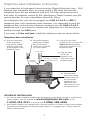
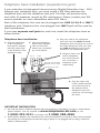
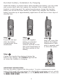
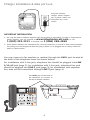
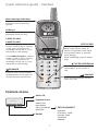
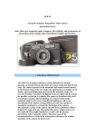
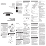
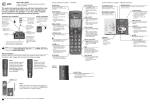
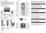
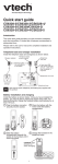
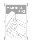
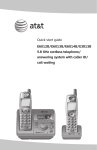
Quick start guide TL76108 5.8 GHz 2-line corded/cordless telephone/answering system with caller ID/call waiting Installation preparation You must install and charge the battery before using the telephone. STOP! See page 5 for easy instructions. If you subscribe to high-speed Internet service (Digital Subscriber Line - DSL) through your telephone lines, you must install a DSL filter between the telephone base and the telephone wall jack (pages 2-4). The filter will prevent noise and caller ID problems caused by DSL interference. Please contact your DSL service provider for more information about DSL filters. Your product may be shipped with a protective sticker covering the handset or telephone base display - remove it before use. For customer service or product information, visit our website at www.telephones.att.com or call 1 (800) 222-3111. In Canada, dial 1 (866) 288-4268. Avoid placing the telephone base too close to: • Communication devices such as: television sets, VCRs, or other cordless telephones. • Excessive heat sources. • Noise sources such as a window with traffic outside, motors, microwave ovens, refrigerators, or fluorescent lighting. • Excessive dust sources such as a workshop or garage. • Excessive moisture. • Extremely low temperature. • Mechanical vibration or shock such as on top of the washing machine or work bench. Telephone base installation (2-line jack) If you subscribe to high-speed Internet service (Digital Subscriber Line - DSL) through your telephone lines, you must install a DSL filter between the telephone base and the telephone wall jack. The filter will prevent noise and caller ID problems caused by DSL interference. Please contact your DSL service provider for more information about DSL filters. The telephone line cord can be plugged into LINE 1/L1+L2 or LINE 2 telephone jack in the telephone base. However, it is suggested to plug the telephone line cord with two telephone numbers into the LINE 1/L1+L2 telephone jack if you intend to connect the telephone to a fax machine or modem through the DATA port. If you have a 2-line wall jack, install the telephone base as shown below. Telephone base installation 1. Plug the small end of the telephone base power adapter into the power jack at the bottom of the telephone base. 2. Plug the telephone base power adapter into an electrical outlet not controlled by a wall switch. 3. Plug one end of the telephone line cord into the LINE 1/L1+L2 telephone jack at the bottom of the telephone base. Line 1+Line 2 Telephone line cord 4. Plug the other end of the telephone line cord into a 2 line DSL filter (not included, telephone jack. required for DSL users). 5. Plug the other end of the coiled handset cord into the jack at the bottom of the telephone base and route the cord through the slots. IMPORTANT INFORMATION 1. Use only the power adapters supplied with this product or equivalent. To order a replacement power adapter, visit our website at www.telephones.att.com, or call 1 (800) 222-3111. In Canada, dial 1 (866) 288-4268. 2. These power adapters are intended to be correctly oriented in a vertical or floor mount position. The prongs are not designed to hold the plug in place if it is plugged into a ceiling, under-thetable or cabinet outlet. Telephone base installation (1-line jack) If you subscribe to high-speed Internet service (Digital Subscriber Line - DSL) through your telephone lines, you must install a DSL filter between the telephone base and the telephone wall jack. The filter will prevent noise and caller ID problems caused by DSL interference. Please contact your DSL service provider for more information about DSL filters. The telephone line cord can be plugged into either LINE 1/L1+L2 or LINE 2 telephone jack. However, you have to plug the telephone line cord into LINE 2 jack if you need to connect to a fax machine or modem through DATA port. All data will only be transmitted through LINE 2 jack. If you have 1-line wall jack, install the telephone base as shown below. Telephone base installation 1. Plug the small end 2. Plug the telephone of the telephone base power adapter base power adapter into an electrical into the power jack outlet not controlled at the bottom of the by a wall switch. telephone base. Telephone line cord 3. Plug one end of the telephone line cord into the LINE 1/L1+L2 or LINE 2 telephone jack at the bottom of the telephone base. 4. Plug the other end of the telephone line cord into a DSL filter (not included, telephone jack. required for DSL users). 5. Plug the other end of the coiled handset cord into the jack at the bottom of the telephone base and route the cord through the slots. IMPORTANT INFORMATION 1. Use only the power adapters supplied with this product or equivalent. To order a replacement power adapter, visit our website at www.telephones.att.com, or call 1 (800) 222-3111. In Canada, dial 1 (866) 288-4268. 2. These power adapters are intended to be correctly oriented in a vertical or floor mount position. The prongs are not designed to hold the plug in place if it is plugged into a ceiling, under-thetable or cabinet outlet. Telephone base installation (separate line jack) If you subscribe to high-speed Internet service (Digital Subscriber Line - DSL) through your telephone lines, you must install a DSL filter between the telephone base and the telephone wall jack. The filter will prevent noise and caller ID problems caused by DSL interference. Please contact your DSL service provider for more information about DSL filters. Each of the telephone line cord can be plugged into LINE 1/L1+L2 or LINE 2 telephone jack. Telephone line cord plugged into LINE 2 jack will be used for data transmission. If you have separate wall jacks for each line, install the telephone base as shown below. Telephone base installation 1. Plug the small end of the telephone base power adapter into the power jack at the bottom of the telephone base. 2. Plug the telephone base power adapter into an electrical outlet not controlled by a wall switch. Line 1 Line 2 3. Plug one end of the telephone line cord into the LINE 1/L1+L2 telephone jack and plug one end of the other telephone line cord into the LINE 2 telephone jack at the bottom of the telephone base. 4. Plug the other end of the telephone line cords into the line 1 and line 2 DSL filter (not included, telephone jacks required for DSL users). respectively. Telephone line cord 5. Plug the other end of the coiled handset cord into the jack at the bottom of the telephone base and route the cord through the slots. IMPORTANT INFORMATION 1. Use only the power adapters supplied with this product or equivalent. To order a replacement power adapter, visit our website at www.telephones.att.com, or call 1 (800) 222-3111. In Canada, dial 1 (866) 288-4268. 2. These power adapters are intended to be correctly oriented in a vertical or floor mount position. The prongs are not designed to hold the plug in place if it is plugged into a ceiling, under-thetable or cabinet outlet. Handset battery installation & charging 89-1324-00-00 MODEL 102 BATTERY PACK 89-1324-00-00 MODEL 102 BATTERY PACK Install the battery as shown below. After installing the battery, you can make and receive short calls, but replace the handset in the charger when the handset is not being used. For optimal performance, charge the handset battery for at least 16 hours before use. When fully charged, the handset battery provides up to approximately eight hours of talk time or four days of standby time. Step 1 Step 2 Step 3 Press the tab and slide the battery compartment cover downwards. Insert the supplied battery as indicated. Insert the top (on contacts and tab) in first, then push downwards on the lower portion of the battery. Align the cover flat against the battery compartment, then slide it upwards until it clicks into place. Step 4 Charge the handset by placing it facing the front in the charger. The CHARGE light will be on when the handset is charging. IMPORTANT INFORMATION Use only the battery supplied with this product. To order a replacement or spare battery (AT&T model 102, part number 89-1324-00-00) or equivalent, visit our website at www.telephones.att.com, or call 1 (800) 222-3111. In Canada, dial 1 (866) 288-4268. Charger installation & data port use Plug the handset charger power adapter into a power outlet not controlled by a wall switch. IMPORTANT INFORMATION 1. Use only the power adapters supplied with this product or equivalent. To order a replacement power adapter, visit our website at www.telephones.att.com, or call 1 (800) 222-3111. In Canada, dial 1 (866) 288-4268. 2. These power adapters are intended to be correctly oriented in a vertical or floor mount position. The prongs are not designed to hold the plug in place if it is plugged into a ceiling, under-thetable or cabinet outlet. You may connect a fax machine or modem through the DATA port located at the back of the telephone base (as shown below). For installation with 2-line jack, telephone line should be plugged into LINE 1/L1+L2 jack (page 2); for installation with 1-line jack, telephone line jack should be plugged into LINE 2 jack (page 3); for installation with separate line, data will be transmitted through LINE 2 jack (page 4). Use DATA port at the back of the telephone to connect to the fax or modem if desired. DATA Quick reference guide - handset New message indicator Flashes when there is a new message in the answering system. Softkeys Press to select an item displayed above the key. LINE1/FLASH, LINE2/FLASH OFF/CLEAR Press LINE1/FLASH to make or answer a call on line 1. During a call, press to receive an incoming call on line 1 if you subscribe to call waiting. During a call, press to hang up. While using menus, press to cancel an operation, back up to the previous menu, or exit the menu display. While predialing, press to delete digit. Press LINE2/FLASH to make or answer a call on line 2. During a call, press to receive an incoming call on line 2 if you subscribe to call waiting. /X-FER/INTERCOM Press to begin an intercom conversation or to transfer a call. SPEAKER Press to turn on the handset speakerphone. Press again to resume normal handset use. /VOLUME Press to adjust listening volume when on a call. Feature menu Caller ID Feature menu HANDSET I RDL MENU CID DIRECTORY MAILBOXES SETUP HANDSET REGISTER Redial SETUP HANDSET RINGERS LOW BATT TONE KEYPAD TONE CONTRAST RENAME Quick reference guide - telephone base INTERCOM/TRANSFER Softkeys Press to begin an intercom conversation or to transfer a call. Press to select the item displayed just above the key. CLEAR While using menus, press to cancel an operation, back up to the previous menu, or exit the menu display. RECORD MUTE Press to record a memo, a telephone conversation, or an outgoing announcement. Press to turn off the microphone; press again to resume your conversation. DELETE VOLUME Press to delete the message currently playing. When no messages are playing, press to delete all messages. Press to adjust the speakerphone volume (if speakerphone is on), message playback volume (during playback), or corded handset volume (when on a call). ON/OFF LINE 1, ON/OFF LINE 2 FLASH Press to turn the answering machine for line 1 or line 2 on or off. MAILBOX LINE 1 MAILBOX LINE 2 During a call, press to receive an incoming call if you subscribe to call waiting. , HEADSET Press to start or stop message playback in the mailbox line 1 or line 2. Press to activate headset. SPEAKER Press to turn the base speakerphone on or off. SPARE BATTERY indicator On while the spare battery is installed and charging. LINE 1, LINE 2 Press and then lift the handset to make or answer a call on line 1 or line 2. REPEAT Press to repeat the message currently playing. Press twice to play the previous message. SKIP Press to skip the message currently playing. For complete instructions, please refer to the user’s manual. If you are unable to find your manual, please visit www.telephones.att.com to read and/or download the manual. www.telephones.att.com © 2008-2009 Advanced American Telephones. All Rights Reserved. AT&T and the AT&T logo are trademarks of AT&T Intellectual Property licensed to Advanced American Telephones, San Antonio, TX 78219. Printed in China. Issue 3 AT&T 09/09.