1
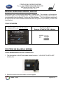
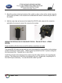
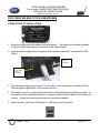
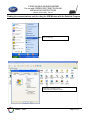
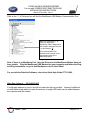
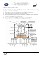
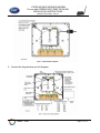
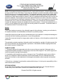
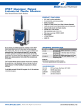
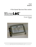
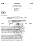
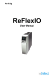
XTEND 900 MHZ WIRELESS MODEM
For use with VEEDER-ROOT EMR³ DATALINK
INSTALLATION INSTRUCTIONS
Manual 577013-859, Rev. B
INTRODUCTION
This Installation Guide Contains the necessary information to Connect the Wireless Modems to the EMR³
Interconnect Box and the Office Computer for running the EMR³ Datalink Program. For Specific
Instructions on Running the Program itself, Refer to the Program Manual that is included on the Software
Disk and the Quick Start Guide that is included with the Office Kit.
THE INSTALLATION INSTRUCTION VARY BY MODEM TYPE – FOLLOW THE INSTRUCTIONS FOR
THE SPECIFIC MODEM YOU HAVE.
DESCRIPTION:
The Wireless Kits come in three types:
Kit Number
0846000-030
Description
Office Kit - XTend 900 MHZ Americas
0846000-031
Truck Kit with Keypad - XTend
900 MHZ - Americas
0846000-032
Truck Kit - XTend 900 MHZ –
Americas
0846000-033
Optional High Gain Antenna Kit
Veeder - Root
General Contents and Comments
The office kit includes:
x Wireless USB modem with standard
antenna,
x Regular USB Cable for connecting the
modem to the office PC,
x Quick Start Guide,
x Installation Guide
x Program Disc. The Program Disc includes
the USB Drivers and the full Program
Manual as a .pdf file.
The Truck Kit with Keypad includes:
x Wireless modem with standard antenna,
x Special RS-232 Cable for Connecting to
Interconnect Box
x Cord grip and Velcro patch
x Installation Guide
x Optional Keypad for EMR³ Register Head
The Truck Kit without Keypad includes:
x Wireless modem with standard antenna,
x Special RS-232 Cable for Connecting to
Interconnect Box
x Cord grip and Velcro patch
x Installation Guide
The Optional High Gain Antenna Kit includes:
x High Gain Antenna
x Mounting bracket
x 20 feet of cable with connectors
Page 1 of 13
XTEND 900 MHZ WIRELESS MODEM
For use with VEEDER-ROOT EMR³ DATALINK
INSTALLATION INSTRUCTIONS
Manual 577013-859, Rev. B
INDIVIDUAL MODEM UNIQUE ADDRESS - IMPORTANT
Each Modem has a Unique Address assigned by Veeder-Root. This number is on the label on
the Modem Itself, and on the Modem Box. For each Truck / Interconnect Box, this number is
your traceability from the Specific Truck to the Office Software. The Truck Modem number will
be entered into the Office Software and identified with the specific Truck Number (or other local
identification).
TRUCK KIT MODEM:
XTend 900 MHz, 1 Watt, Serial
Approved for use in the Americas
Unique Address Assigned
By Veeder-Root
Example of Label on Side of Modem
FOR XTEND 900 MHz SERIAL MODEMS
TRUCK MODEM MOUNTING AND CONNECTION:
1. The dip switches on the XTend modem should be set to: 1=ON 2=OFF 3=OFF 4=OFF
5=ON 6=ON
2. Screw the antenna into the modem and hand tighten.
Veeder - Root
Page 2 of 13
XTEND 900 MHZ WIRELESS MODEM
For use with VEEDER-ROOT EMR³ DATALINK
INSTALLATION INSTRUCTIONS
Manual 577013-859, Rev. B
3. Mount the modem to the back window of the vehicle or other surface of the vehicle using the
Velcro patch provided, or the modem can be attached with screws or bolts using the tabs on
the modem.
4. Add the screw clips and screws to the head of the RS-232 cable, plug into the connector,
and tighten the screws to secure the connector the modem.
WIRING THE SPECIAL RS-232 CABLE INTO THE IB – TRUCK KIT ONLY – XTEND
MODEM:
Power should be off to the Interconnect Box before connections are made.
The special RS-232 cable included with the truck kit provides the communication to the wireless
modem and also the modem power. Modem power is provided from the V+ power coming into
the Interconnect Box. Normally the V+ wire is Red.
Install the cord grip in the interconnect box and connect the cable wires by color according the
pictures. The connectors in the IB are only designed for up to 18 gage wire, so splitting the V+
into the IB may be necessary. You can shorten the cable if you like.
Veeder - Root
Page 3 of 13
XTEND 900 MHZ WIRELESS MODEM
For use with VEEDER-ROOT EMR³ DATALINK
INSTALLATION INSTRUCTIONS
Manual 577013-859, Rev. B
For XTend Modem: Green is RX, Black is TX, White is Ground, Red is V+
RS-232
Connect:
Green RX
Black TX
White
Ground
Red V+
Red to
V+
V+ from
Vehicle
RS-232
special
cable
VOr
Battery
Ground
Upon completion of the wiring and power to the IB is turned on, the red light on the modem next to the
RS-232 connector will be on.
Red Light on
with Power
to IB
Before leaving the vehicle, go to the display, and make sure the PORT 2 ASSIGN under
SETUP, SYSTEM ADDRESS is set to OBC.
x
Push the MODE button to get to SETUP, Arrow Up to SYSTEM ADDRESS, NEXT to IB
ADDRESS, Arrow up to PORT 2 ASSIGN, NEXT, if not OBC the Arrow to OBC and ENTER,
ENTER, and ENTER. You can then push the MODE button to get back to Volume Mode.
Veeder - Root
Page 4 of 13
XTEND 900 MHZ WIRELESS MODEM
For use with VEEDER-ROOT EMR³ DATALINK
INSTALLATION INSTRUCTIONS
Manual 577013-859, Rev. B
FOR XTEND 900 MHZ OFFICE USB MODEMS
XTEND OFFICE KIT INSTALLATION:
1. Screw the antenna into the modem and hand tighten. The antenna should point upwards.
If using the High Gain Antenna, it connects to the same location.
2. Insert the power supply cable connector into the modem completely, and attach the USB
CABLE
Power
supply
connection
3 Green
Lights when
power
connected.
3. Plug the power supply into a normal 110 volt outlet, or with the proper non-Americas Plug.
The three green signal lights on the modem will be lit.
4. The modem can sit on a desk, but for best results it should be place as high as possible. Or,
the modem can be attached with Velcro, or screws or bolts using the tabs on the modem to a
surface. A high gain antenna will enhance the modems capability.
5. Attach the other end of the USB Cable to a USB port on your computer.
Veeder - Root
Page 5 of 13
XTEND 900 MHZ WIRELESS MODEM
For use with VEEDER-ROOT EMR³ DATALINK
INSTALLATION INSTRUCTIONS
Manual 577013-859, Rev. B
INSTALLING USB MODEM DRIVERS
The Modem is a “plug-and-play” device that should automatically be detected by your PC.
“Found New Hardware Wizard” dialog box appears
1. Verify the Program CD is inserted into the CD Drive.
2. Select the ‘Install from specific list or location (Advanced)’ option; then select
the ‘Next’ button.
3. Select the "Search for best driver in these locations" option and check the
‘Search removable media (CD-ROM...)’ box.
4. Select the ‘Next’ button.
Hardware Installation "Windows Logo Testing" alert box appears
5. Select the ‘Continue Anyway’ button.
6. Select the ‘Finish’ button.
7. Repeat steps 1 through 5 to install the second driver.
8. (Re-boot computer if prompted to do so.)
Once the Modem drivers are successfully loaded the Red LED on the Modem will be lit
indicating a successful USB Link.
Veeder - Root
Page 6 of 13
XTEND 900 MHZ WIRELESS MODEM
For use with VEEDER-ROOT EMR³ DATALINK
INSTALLATION INSTRUCTIONS
Manual 577013-859, Rev. B
Finding the communications port for using the USB Modem with the DataLink Program
Start, Control Panel
Double Click on System to get the
System Properties Window to the left
Veeder - Root
Page 7 of 13
XTEND 900 MHZ WIRELESS MODEM
For use with VEEDER-ROOT EMR³ DATALINK
INSTALLATION INSTRUCTIONS
Manual 577013-859, Rev. B
Click on the Hardware Tab
Click on Device Manager
Device Manager Screen:
Veeder - Root
Page 8 of 13
XTEND 900 MHZ WIRELESS MODEM
For use with VEEDER-ROOT EMR³ DATALINK
INSTALLATION INSTRUCTIONS
Manual 577013-859, Rev. B
Click on the “+” of Ports and you will find the MaxStream USB Modem Communication Port.
When you click on the “+” of
Ports, you will find the
MaxStream PKG-U Modem and
the computer assigned Com port
- In this example “6”.
This Communication Port
Number will be entered on the
Configuration page of the
DataLink program.
Note: If there is no MaxSteam Port, then the Drivers for the MaxStream Modem have not
been loaded. Plug the MaxStream USB Modem into your computer and follow the Plugand-Play instructions, or got to Add Hardware on the Control Panel.
For use with the DataLink Software, refer to the Quick Help Guide 577013-860.
High Gain Antenna - Kit 0846000-033
If a high gain antenna is used, it should be located as high as possible. Instead of additional
co-axial cable being added to locate the antenna, a longer USB cable can be added between
the computer and the modem.
Veeder - Root
Page 9 of 13
XTEND 900 MHZ WIRELESS MODEM
For use with VEEDER-ROOT EMR³ DATALINK
INSTALLATION INSTRUCTIONS
Manual 577013-859, Rev. B
OPTIONAL KEYPAD INSTALLATION:
In order to install the optional Keypad, the Display will need to be disconnected from the wiring
and gently removed from the housing.
1. Remove the cover from the hole in the right side of the display head housing.
2. Put the rubber gasket over the threads on the keypad outlet.
3. Align the gasket and keypad to the holes in the housing and with a T-15 Torx, secure the
keypad to the housing with the screws provided.
4. Insert the display in the housing, gently pushing down to seat completely.
5. Reconnect the wires to the display per the following wiring information:
Veeder - Root
Page 10 of 13
XTEND 900 MHZ WIRELESS MODEM
For use with VEEDER-ROOT EMR³ DATALINK
INSTALLATION INSTRUCTIONS
Manual 577013-859, Rev. B
6. Connect the keypad wires per this diagram:
Veeder - Root
Page 11 of 13
XTEND 900 MHZ WIRELESS MODEM
For use with VEEDER-ROOT EMR³ DATALINK
INSTALLATION INSTRUCTIONS
Manual 577013-859, Rev. B
Warranty of Modems by MaxStream :
Extracted From MaxStream XTend-PKG-R™ RF Modem Product Manual v2.x4x
RF Modems from MaxStream, Inc. (the ȈProductȈ) are warranted against defects in materials and
workmanship under normal use, for a period of 1-year from the date of purchase. In the event of a
product failure due to materials or workmanship, MaxStream will repair or replace the defective
product. For warranty service, return the defective product to MaxStream, shipping prepaid, for
prompt repair or replacement.
The foregoing sets forth the full extent of MaxStreamȇs warranties regarding the Product. Repair or
replacement at MaxStreamȇs option is the exclusive remedy. THIS WARRANTY IS GIVEN IN LIEU
OF ALL OTHER WARRANTIES, EXPRESS OR IMPLIED, AND MAXSTREAM SPECIFICALLY
DISCLAIMS ALL WARRANTIES OF MERCHANTABILITY OR FITNESS FOR A PARTICULAR
PURPOSE. IN NO EVENT SHALL MAXSTREAM, ITS SUPPLIERS OR LICENSORS BE LIABLE
FOR DAMAGES IN EXCESS OF THE PURCHASE PRICE OF THE PRODUCT, FOR ANY LOSS
OF USE, LOSS OF TIME, INCONVENIENCE, COMMERCIAL LOSS, LOST PROFITS OR
SAVINGS, OR OTHER INCIDENTAL, SPECIAL OR CONSEQUENTIAL DAMAGES ARISING OUT
OF THE USE OR INABILITY TO USE THE PRODUCT, TO THE FULL EXTENT SUCH MAY BE
DISCLAIMED BY LAW. SOME STATES DO NOT ALLOW THE EXCLUSION OR LIMITATION OF
INCIDENTAL OR CONSEQUENTIAL DAMAGES. THEREFOR, THE FOREGOING EXCLUSIONS
MAY NOT APPLY IN ALL CASES. This warranty provides specific legal rights. Other rights which
vary from state to state may also apply.
ȱ
MODEM CERTIFICATIONS:
Extracted From MaxStream XTend-PKG-R™ RF Modem Product Manual v2.x4x and 9XTend-PKG RF
Modems Datasheet 2005.
Certifications:
FCC Part 15.247
Industry Canada
ID: OUR-9XTEND
ID: 4214A-9XTEND
FCC Certification
The XTend RF Modem complies with Part 15 of the FCC Rules. In order to inherit MaxStream’s FCC
Certification, compliance requires the following be stated on the device and within its operation manual:
FCC ID: OUR-9XTEND This device complies with Part 15 of the FCC Rules. Operation is subject to the
following two conditions: (1) this device may not cause harmful interference and (2) this device must
accept any interference received, including interference that may cause undesired operation.
Veeder - Root
Page 12 of 13
XTEND 900 MHZ WIRELESS MODEM
For use with VEEDER-ROOT EMR³ DATALINK
INSTALLATION INSTRUCTIONS
Manual 577013-859, Rev. B
NOTE: This equipment has been tested and found to comply with the limits for a Class B digital device,
pursuant to Part 15 of the FCC Rules. These limits are designed to provide reasonable protection against
harmful interference in a residential installation. This equipment generates, uses and can radiate radio
frequency energy and, if not installed and used in accordance with the instructions, may cause harmful
interference to radio communications. However, there is no guarantee that interference will not occur in a
particular installation. If this equipment does cause harmful interference to radio or television reception,
which can be determined by turning the equipment off and on, the user is encouraged to try to correct the
interference by one or more of the following measures: • Reorient or relocate the receiving antenna. •
Increase the separation between the equipment and receiving modem. • Connect the equipment into an
outlet on a circuit different from that to which the receiving modem is connected. • Consult the dealer or
an experienced radio/TV technician for help.
Notice
Veeder-Root makes no warranty of any kind with regard to this publication, including, but not limited to,
the implied warranties of merchantability and fitness for a particular purpose.
Veeder-Root shall not be liable for errors contained herein or for incidental or consequential damages in
connection with the furnishing, performance, or use of this publication.
Veeder-Root reserves the right to change system options or features, or the information contained in this
publication.
This publication contains proprietary information which is protected by copyright. All rights reserved. No
part of this publication may be photocopied, reproduced, or translated to another language without the
prior written consent of Veeder-Root.
DAMAGE CLAIMS
1. Thoroughly examine all components and units as soon as they are received. If damaged, write a
complete and detailed description of the damage on the face of the freight bill. The carrier's agent must
verify the inspection and sign the description.
2. Immediately notify the delivering carrier of damage or loss. This notification may be given either in
person or by telephone. Written confirmation must be mailed within 48 hours. Railroads and motor
carriers are reluctant to make adjustments for damaged merchandise unless inspected and reported
promptly.
3. Risk of loss, or damage to merchandise remains with the buyer. It is the buyer's responsibility to file a
claim with the carrier involved.
RETURN SHIPPING
For the parts return procedure, please follow the appropriate instructions in the "General Returned
Goods Policy" and "Parts Return" section of the Veeder-Root EMR³ price list.
©Veeder-Root 2006. All rights reserved.
Veeder - Root
Page 13 of 13