1
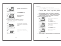
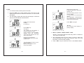
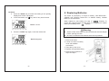
INSTRUCTION MANUAL
DUAL DISPLAY L C R METER
Table of Contents
I.
Introduction………………………….................
II.
Measuring Principle Introduction…………
03
04 ~ 07
III. Panel Illustration………................................ 08 ~ 10
Model : DE-5000
IV. LCD Display Illustration………………..……… 11 ~ 12
V.
Thank you for purchasing our products. Please read this
instruction manual before using the meter and keep it
properly for contingent use.
Operation Instructions………………..……….. 13 ~ 34
1.
2.
3.
4.
Power ON/OFF …………………….………….
CAL …………………………………………….
LCR AUTO ……………………………………..
Inductance / Capacitance / Resistance
Measurement………………………………….
5. FREQ …………………………………………..
6. Backlight ……………………………………….
7. SORTING / SETUP / ENTER …………….....
8. PC ………………………………………………
9. D/Q/ESR/ș ……………………………………..
10. SER/PAL ……………………………………….
11. REL …………………………………………….
12. HOLD …………………………………………...
13 ~ 14
15 ~ 17
18 ~ 20
VI. Replacing Batteries……………..………………
33
VII. General Specification……………..……………
34
20 ~ 21
22 ~ 23
23
23 ~ 25
26
27 ~ 28
29
30 ~ 31
32
VIII. Electrical Specification……………..…………. 35 ~36
-1-
I. Introduction
Electrical Symbol
Risk of Danger. Important information.
See Manual.
AC/DC power adaptor input polarity
Current battery capacity indicator
Warning
Ɣ Discharge test device before measuring.
Ɣ Do not open the case of meter during measurement.
Ɣ After measurement, power off the meter. As there will be
slight power consumption under auto power off mode.
Ɣ Take the batteries out of the meter if it will be left idle for a
long time.
Ɣ Do not use organic solvent to clean the meter. Wipe it with
a soft cloth, if necessary.
Ɣ
means battery capacity is full.
Once
is
displayed which indicates power is low for operation and
please replace battery immediately to secure the accuracy
in specification.
This LCR Meter is a 19999/ 9999 counts dual display, high
accuracy LCR meter, which could measure Inductance/
Capacitance/ Resistance with secondary parameters including
dissipation factor (D), quality factor (Q), phase angle (ș),
equivalent series/ parallel resistance (ESR or Rp).
This LCR Meter is fully auto ranging operation for AC
impedance & DC resistance measurement. The user could
measure the L/C/R components directly in “AUTO-LCR
“ smart mode without selecting the function key.
Components could be measured in series or parallel mode
according to the DUT (device under test) impedance
automatically.
User could select the desired
100Hz/120Hz/1kHz/10kHz /100kHz.
test
frequencies
of
The “SORTING ” mode could help the user to make a quick
sort for a bunch of components.
The LCD display with the backlight for easy reading in dark
places.
With a 9V battery operation is standard for the meter, but a DC
9V adaptor can also be used as an optional power input.
The test data can be transferred to PC through an optional full
isolated optical USB-IR interface.
-2-
-3-
II. Measuring Principle Introduction
Impedance parameter introduction
䎷䏋䏈䎃 䏌䏐䏓䏈䏇䏄䏑䏆䏈䎃 䏆䏒䏑䏖䏌䏖䏗䏖䎃 䏒䏉䎃 䏕䏈䏖䏌䏖䏗䏄䏑䏆䏈䎃 䎋䏕䏈䏄䏏䎃 䏓䏄䏕䏗䎌䎃 䏄䏑䏇䎃 䏕䏈䏄䏆䏗䏄䏑䏆䏈䎃
䎋䏌䏐䏄䏊䏌䏑䏄䏕䏜䎃 䏓䏄䏕䏗䎌䎑䎃 䎩䏒䏕䎃 䏈䏛䏄䏐䏓䏏䏈䎏䎃 䎽䏖䎃 䏕䏈䏓䏕䏈䏖䏈䏑䏗䏖䎃 䏗䏋䏈䎃 䏌䏐䏓䏈䏇䏄䏑䏆䏈䎃 䏌䏑䎃
䏖䏈䏕䏌䏈䏖䎃䏐䏒䏇䏈䎑䎃䎽䏖䎃䏆䏄䏑䎃䏅䏈䎃䏇䏈䏉䏌䏑䏈䏇䎃䏄䎃䏆䏒䏐䏅䏌䏑䏄䏗䏌䏒䏑䎃䏒䏉䎃䏕䏈䏖䏌䏖䏗䏄䏑䏆䏈䎃䎵䏖䎃䏄䏑䏇䎃
䏕䏈䏄䏆䏗䏄䏑䏆䏈䎃䎻䏖䎑䎃䎬䏗䎃䏄䏏䏖䏒䎃䏆䏒䏘䏏䏇䎃䏅䏈䎃䏇䏈䏉䏌䏑䏈䏇䎃䏄䏖䎃䏄䎃䏟䎽䏟䎃䎋䏟䎽䏟䎃䎠䎃 䎵䏖䎕䎃䎎䎃䎻䏖䎕䎃 䎌䎃
䏒䏉䎃䏐䏄䏊䏑䏌䏗䏘䏇䏈䎃䏚䏌䏗䏋䎃䏄䎃䏓䏋䏄䏖䏈䎃䏄䏑䏊䏏䏈䎃䕠䎑䎃
If ș > 0, the reactance is inductive. In other words, if ș < 0, the
reactance is capacitive.
There are two types for reactance. The one is the inductive
reactance XL and the other is the capacitive reactance XC.
䎃
䎷䏋䏈䏜䎃䏆䏒䏘䏏䏇䎃䏅䏈䎃䏇䏈䏉䏌䏑䏈䏇䎃䏄䏖䎝䎃 䎃
䎋䏉䎃䎠䎃䏖䏌䏊䏑䏄䏏䎃䏉䏕䏈䏔䏘䏈䏑䏆䏜䎌䎃 䎃
XL = 2 ʌf L䎃 䎃 䎃 䎃 䎃 䎋䎯䎃䎠䎃䎬䏑䏇䏘䏆䏗䏄䏑䏆䏈䎌䎃 䎃
XC =1/ (2 ʌf C)䎃 䎃 䎋䎦䎃䎠䎃䎦䏄䏓䏄䏆䏌䏗䏄䏑䏆䏈䎌䎃 䎃
Measurement mode
The impedance could be measured in series or parallel
mode. The impedance Z in parallel mode could be represented
as reciprocal of admittance Y. The admittance could be defined
as Y = G + jB. The G is the conductance and the B is the
susceptance.
䎃
Y = 1/Z = 1/Rp + 1/jXp = G+jB
Rs: Resistance in series mode
Xs: Reactance in series mode
Cs: Capacitance in series mode
Ls: Inductance in series mode
Zs = Rs + jXs or |Zs|Иș
Rs = |Zs| cosș
Xs = |Zs| sinș
Xs/Rs = tanș
ș = tan-1(Xs/Rs)
-4-
Rp: Resistance in parallel mode
Xp: Reactance in parallel mode
Cp: Capacitance in parallel mode
Lp: Inductance in parallel mode
-5-
There are two factors to provide the ratio of real part and
imaginary part. Usually the quality factor Q is used for
inductance measurement and the dissipation factor D is used
for capacitance measurement. D factor is defined as a
reciprocal of Q factor.
Q = 1 / D = tanș
Q = Xs / Rs = 2ʌf Ls / Rs = 1 / 2ʌf Cs Rs
Q = B / G = Rp / | Xp | = Rp / 2ʌf Lp = 2ʌf Cp Rp
Actually, Rs and Rp are existed in the equivalent circuit of
capacitor or inductor. If the capacitor is small, Rp is more
important than Rs. If capacitor is large, the Rs is more
important also. Therefore, use parallel mode to measure lower
value capacitor and use series mode to measure higher value
capacitor. For inductor, the impedance relationship is different
from capacitor. If the inductor is small, Rp is almost no effect. If
inductor is large, the Rs is no effect also. Therefore, use series
mode to measure lower value inductor and use parallel mode to
measure higher value inductor.
ZM is defined as total impedance measured to DUT
( device under test ) by the special test fixture which has some
parasitic impedance.
ZM = (Rs + jȦLs) + ((Go+jȦCo)-1 || ZDUT)
ZDUT is the target impedance user wants to realize. It is
necessary to use the open/short calibration process to cancel
the effect of Rs+jȦLs and Go+jȦCo.
Equivalent circuit
Open/short calibration
process to get the better accuracy for high/low impedance
measurement. The purpose of open/short calibration is to
reduce the parasitic effect of the test fixture.
-6-
-7-
ijIJįġ ŕōĮijIJ Alligator
Panel Illustration
Test Lead Case
ijijįġŕōĮijij SMD
tweezers (optional)
Rear
ijĴįġŕōĮijĴ Guard Line
Front panel
Side
“GUARD” provides shield for DUT ( device under test ),
improvised test leads or equipments situated at places where
with high interference.
-8-
IR to USB case
(optional)
-9-
1.
2.
3.
4.
5.
6.
7.
8.
9.
10.
11.
12.
13.
14.
15.
16.
17.
18.
19.
20.
21.
22.
23.
III. LCD Display Illustration
LCD display
POWER
To power on/off the instrument
LCR auto mode, Inductance,
Capacitance, Resistance and DC
LCR AUTO
resistance measurement selection key
FREQ
Testing frequency selection key
Backlight display
SORTING
Sorting mode control key
PC
UART output control
CAL
Open/Short calibration mode
D/Q/ ESR/ș
D/Q/ ESR/ș parameters selection key
Setup menu control key
SETUP
(in sorting mode )
SER/PAL
Series and Parallel selection key
Setup menu control key
ENTER
(in sorting mode )
REL%
Relative mode
HOLD
Data hold
Input sockets and Terminals
AC/DC power adaptor
Battery cover
Tilt-Stand
IR to USB Slot
IR to USB case (optional)
TL-21 Alligator Test Lead Case
TL-22 SMD tweezers (optional)
TL-23 Guard Line
- 10 -
LCD Display.
1.
Sorting
2.
Tol
3.
kHz
4.
5.
PC
6.
Range
7.
8.
9.
10.
11.
12.
13.
Sorting function is enabled
Tolerance indication in sorting mode : ±0.25%, ±0.5%,
± 1%, ±2%, ±5%, ±10%, ±20%, & +80%-20%
Testing frequency indication –
1kHz,10kHz,100kHz,100Hz & 120Hz
Communication is active
Auto
Battery capacity indication
Range selection is enabled on setup menu of sorting
mode
Auto range for L, C or R measurement
LCR
Checking for L/C/R mode automatically
ǻ
Relative function is enabled
Ls/Lp
Cs/Cp
Inductance in series or parallel mode is active
Capacitance in series or parallel mode is active
Rs/Rp
AC Resistance in series or parallel mode is active
DCR
DC resistance mode is selected
- 11 -
14.
D/Q/ș
15.
16.
17.
18.
19.
20.
21.
Rp
Dissipation factor, Quality factor or Phase angle is
active for L/C measurement mode
AC Resistance in parallel mode is active
Cal
HOLD
Open/Short calibration mode
Data Hold
APO
Auto power off mode
ESR
Series equivalent resistance mode
Secondary Display
29.
Phase angle unit
Unit for Resistance (ȍ, kȍ and Mȍ )
– on secondary display
Unit for Capacitance ( pF, nF, ȝF and mF )
– on secondary display
Unit for Inductance ( ȝH, mH and H)
– on secondary display
The percentage display in relative mode
– on secondary display
Primary Display
Unit for Resistance ( ȍ, kȍ and Mȍ )
– on primary display
Unit for Inductance ( ȝH,mH and H)
– on primary display
Unit for Capacitance ( pF,nF,ȝF and mF )
– on primary display
30.
Bar-graph display
22.
°
Mkȍ
23.
24.
25.
%
26.
27.
Mkȍ
28.
y
Special Indication Characters
Indicates short calibration
ġ
ġ
IV. Operation Instructions
To access optimum precision for all L, C and R measurements
especially at the highest and the lowest ranges, please use the
alligator test leads (TL-21) or improvised test leads applying to the
measurement for OPEN and SHORT calibration (refer to page
15~17) to reduce the parasitic effect of the test fixture before going
forward the measurement.
To secure the accuracy in specification, please only connect DUT
(device under test) to measuring socket or use TL-21 (standard
accessory) or TL-22 (optional accessory) for measurement.
If use improvised test lead for measurement please prevent using
long wire which may have incorrect result.
1. Power ON/OFF
y When power on, all symbols will display for 2 seconds.
y In Auto Power off mode, APO will be shown on the display. It
will power off automatically, if without any key operation or
measurement for 5 min. Buzzer will beep three times to
remind auto power off is ready to activate and then “OFF”
display to power off.
Indicates open calibration
- 12 -
- 13 -
y
y
y
The default setting is LCR auto mode at test frequency 1kHz.
Battery condition is detected every second and displayed.
suggests battery capacity is full
suggests power is
low and needs to be replaced a new battery.
If the key functions, the buzzer beeps once when key is
pressed. If the key has no function, the buzzer beeps twice
when key is pressed.
2. CAL
y This function enables the LCR meter’s internal parameters
and external connector residues to be calibrated to have
better and precise measurements.
y To make better precision measurements on extremely high
or low impedance ranges of L,C,R, it is highly recommended
that do OPEN/SHORT calibration to reduce the parasitic
effect of the test fixture before measuring.
y Note: Remove any leads or DUT ( device under test ) from
the meter during this procedure. If leaving them connected,
will add impedance to the circuit causing the calibration to
fail indicated by FAIL showing on the display.
Ex. Operation for open and
short calibration with TL-21
Ex. Operation for open and short
calibration with .TL-22
Using adaptor as power supply,
Auto Power off function disables
automatically and “APO”
disappears.
y Auto power off function is disabled automatically, when
using a 9V adaptor as the alternative power supply.
Open Cal.
Short Cal.
Short Cal.
Using 9V- battery as power
supply, “APO” displays.
y
Auto power off function enables when using a 9V-battery as
power supply.
- 14 -
Open Cal.
y Connect TL-21 (or improved test leads applied to the
measurements) and press “CAL” key > 2 seconds to enter
the calibration mode ĺ OPEN ready ĺ OPEN calibration ĺ
SHORT ready ĺ SHORT calibration.
Follow below
procedure to complete the calibration.
y When start the open or short calibration, it will have 30
seconds countdown shown on the display.
- 15 -
y If calibration is completed, PASS or FAIL appears on the
primary display.
y If both calibrations are passed, press ”CAL” key again to
store the calibration value to EEPROM.(Electrically Erasable
Programmable Read-Only Memory).
Enter short calibration mode.
* Short alligator test leads.
Press “ CAL ” key
Display the measurement reading
Start the short calibration with
30-seconds countdown
Press “ CAL ” key for 2sec.
SHORT calibration is completed
PASS or FAIL will appear on the
primary display
* If FAIL, run the procedure from
the first step again.
Enter to open calibration mode
Press “ CAL ” key
Press “ CAL ” key
Start the open calibration with
30-seconds countdown
Calibration is completed
Return to testing mode.
OPEN calibration is completed.
Pass or Fail will appear on the
primary display
* If FAIL, run the procedure from
the first step again.
Press “ CAL ” key
- 16 -
When open or short calibration
fails. “FAIL” will appear on the
primary display.
y If fails in calibration, please double check the DUT( device
under test ) is in the right calibration position and resume the
open and short calibration procedures.
- 17 -
3. LCR AUTO
y
y
The “LCR AUTO” key selects the primary parameter
measurement function. Each press of the key will select
either Auto-LCR mode, Auto-L mode, Auto-C mode, Auto-R
mode or Auto-DCR mode *1.
The default setting is LCR Auto *1 mode which can check the
type of Impedance smartly and enter to the measurement
function automatically.
Enter Auto R mode
Press “LCR AUTO ” key
Enter DCR mode
In LCR AUTO test mode
Press “LCR AUTO ” key
Press “LCR AUTO ” key
Back to LCR AUTO test mode
Enter Auto L mode
y When Auto-L or Auto-C mode is selected, the impedance
measurement is auto ranging.
y The primary display will show the parameter of inductance,
capacitance or resistance of DUT ( device under test ).
Press “LCR AUTO ” key
y The secondary display will show the quality or dissipation
Enter Auto C mode
Press “LCR AUTO ” key
- 18 -
y
factor of DUT ( device under test ).
The secondary parameter will be based on the L/C/R
measurement. It means that (L + Q), (C + D) *2, (R + ș) *3 are
combined in one group respectively.
*1: If |Q| < 0.2, the Auto-R mode will be selected automatically. The
parameter on sub-display is ș.
If Q Њ0.2, the Auto-L mode will be selected automatically. The
parameter on sub-display is Q.
If Q Њ-0.2, Auto-C mode will be selected automatically. The
parameter on sub-display is D.
- 19 -
If C < 5pF. The parameter on sub-display is Rp.
*2: When LCR Auto mode is active, the secondary parameter will show
the equivalent resistance in parallel mode (Rp) to replace the D
factor if the C value of DUT is less than 5pF.
*3: LCR AUTO mode only. In Auto-R mode or DCR mode, the
secondary parameter is not available.
c. To measure SMD component by SMD tweezers
option).
(TL-22,
4. Inductance / Capacitance / Resistance Measurement
y Power on the meter, the default testing mode is LCR Auto
y
mode that can enter to the L/C/R measurement
automatically.
Each press of the key will select either Auto-LCR mode,
Auto-L mode, Auto-C mode, Auto-R mode or Auto-DCR
mode.
a. Insert DIP component leads to
the sockets directly. or
If required, Guard line (TL-23) can
provide shield for DUT (device
under test ) preventing from
interference when measuring high
impedance component
b. To measure DIP and SMD
component by Alligator Test
Lead Case (TL-21)
SMD Tweezers
(TL-22)
If required, Guard line (TL-23) can
provide shield for DUT (device
under test ) preventing from
interference when measuring high
impedance component
Alligator Test Lead
Case (TL-21)
- 20 -
ġ
ɏʳ To make better precision measurements on extremely high or
low impedance ranges of L,C,R, it is highly recommended
that do OPEN/SHORT calibration before testing. ġ
Warning : To avoid electric shock, please discharge the capacitor
before testing.
- 21 -
5. FREQ
y
The “FREQ” key selects the testing frequency. Each press of
the key will select either 1kHz, 10 kHz, 100kHz, 100Hz or
120Hz, total 5 frequency for selection.
y
The default frequency setting is 1kHz.
The test frequency is 120Hz.
Press “FREQ ” key
The testing frequency is 1kHz.
Press “FREQ ” key
Back to test frequency 1 kHz
y The LCR impedance scale ranges are based on the test
frequency.
The testing frequency is 10kHz.
6.
Backlight
y Press“
Press “FREQ ” key
”key to toggle backlight on/off.
y The backlight will be disabled in 60 seconds automatically from
the last operation of pushing any key or measurement.
The test frequency is 100kHz.
7. SORTING / SETUP / ENTER
Press “FREQ ” key
y These key functions are disabled in LCR AUTO mode.
y Press “LCR AUTO ” key to select primary parameter
measurement function.
The test frequency is 100Hz.
Press “FREQ ” key
- 22 -
y In measurement (connect DUT), press “ SORTING ” key to
enter the sorting mode which will be set to 2000 digits display
automatically. If the reading is OL or less than 200 counts, the
sorting function is disabled.
- 23 -
y The primary display will show PASS or FAIL which based on
whether the impedance measured exceeds tolerance range.
The secondary display will show the measurement reading.
Last digit will flash
Press “Ż / Ź” key to select the
desired digit.
Press “Ÿ / ź” key to adjust value.
y When sorting mode is active, operate “ SETUP ” key along with
“Ż / Ź” key, “Ÿ / ź” key and “Enter” key to set the reference
value, range and tolerance.
Press “ ENTER ” key
y When the setup is finished, press “ ENTER ” key to confirm.
“Tol ±” will flash.
Press“Ż / Ź”key to select Tol.
value : Each press of the key will
select either
±1%,±2%,±5%,±10%,
±20%, -20%+80%, ±0.25% or
±0.5%.
Figure : Setting up the reference value for sorting
Display the measurement reading
Press “ ENTER ” key
Press “ SORTING ” key
Setup is completed.
The measurement reading is
shown on the secondary display.
Press “ SETUP ” key
“Range” will appear and flash.
Push “Ż / Ź” key to select the
position of decimal point and units
based on the components you
measure
Press “ ENTER ” key
- 24 -
Ɣ If DUT ( device under test ) is
in the specified Tol % , buzzer
beeps once and the primary
display will show “PASS”.
y If DUT ( device under test ) is out
of the specified Tol %, the
primary display will show
“ FAIL ”.
- 25 -
8. PC
(IR to USB case is optionel. Measuring
data can be transferred to PC with it. )
IR to USB case
USB socket
y Snap on IR to USB case and connect
with USB cable to PC.
y Press “ PC ” key to start data
transmission, and the “PC” will appear on
display. Press the “ PC ” key again to
cancel the transmission.
9.
D/Q/ESR/ș
y In LCR Auto mode, this key has no function
y The “D/Q/ESR/ș ”key selects the secondary parameter
measurement function. Each press of the key will select
either dissipation (D), quality (Q), ESR or phase angel (ș).
Example : In Cs testing mode
Secondary display parameter is
D.
Display the measurement reading
Press “ D/Q/ESR/ș ” key
Press “ PC ” key
Secondary display parameter is
Q.
PC communication is active.
“PC” will appear on the display
Press “ D/Q/ESR/ș ” key
Press “ PC ” key
Secondary display parameter is
ESR.
“PC” disappear on the display
when PC communication is
inactive
- 26 -
Press “ D/Q/ESR/ș ” key
- 27 -
Secondary display parameter is
ș.
Press “ D/Q/ESR/ș ” key
Back to parameter D
measurement
10. SER/PAL
y In LCR Auto mode, this key has no function.
y Press the “SER/PAL” key to select parallel or series mode,.
y When any one of primary parameter measurement function
is selected, parallel or series mode will be selected
automatically based on the total equivalent impedance
measured.
y If the impedance is more than 100kȍ, will be in the parallel
mode automatically. Lp, Cp or Rp appears on the display.
y If the impedance is less than 100kȍ, will be in the series
mode automatically. Ls, Cs or Rs appears on the display.
Example : In Cs and Cp testing mode
When measure capacitance in
series mode.
Ɣ D/Q/ESR/ș setting is not applied to resistance
measurement- Auto-R mode and DCR mode.
“Cs” will appear.
Press “SER/PAL ” key
In Auto-R mode, no parameter
When measure capacitance In
measurement on the secondary
Parallel mode.
display.
“Cp” is shown.
Press “SER/PAL ” key
In DCR mode, no parameter
Back to Series mode.
measurement on the secondary
“Cs” is shown.
display.
y The annunciators for Ls/Lp/Cs/Cp/Rs/Rp will be indicated based
on LCR measurement mode.
- 28 -
- 29 -
11. REL
Remove the current DUT
( device under test ) and insert
another one
y In LCR Auto mode, this key has no function.
y Press the “REL” key to enter relative mode. The value on the
display will be stored as reference value and “ǻ” annunciator
will appear.
The new reading is shown on the
primary display.
***% is shown on the secondary
display.
(All subsequent measurements
will be displayed as a percentage
value to the stored value )
y The secondary display will show the percentage of reference
value for all subsequent measurements
Press “REL” key again
Display the measurement
reading
Ex. 669.3 nF
“ǻ” flash
The reference value display on
primary display.
Press “REL” key
“ǻ” appear
The reading on the display is
stored as reference value.
0.0% is shown on the secondary
display( since the measured
value and the reference are the
same at this point )
y REL% = (DCUR – DREF) / DREF * 100%.
Remove the current DUT
( device under test ) and insert
another one
y The percentage range is from -99.9% to 99.9%. When the
new measurement is double than reference value. OL% will
be shown on the secondary display.
*DCUR = Current DUT(device under test), DREF = Reference
DUT (device under test )
y Press “ REL ” key for more than 2 sec. to exit Relative Mode.
The new reading is shown on the
primary display.
Minus ***% is shown on the
secondary display.
- 30 -
- 31 -
12. HOLD
y
y
V. Replacing Batteries
Press the “HOLD” key to freeze the reading on the primary
display and “HOLD” will appear.
In the Hold mode, only
key and PC key have function.
“HOLD” is shown.
The meter is powered by a single 9V battery, with NEDA1604 ,
JIS006P and IEC6F22 carbon-zinc or alkaline battery. Alkaline
battery is recommended.
“ displays. To
When replaces a new battery, the sign of ”
ensure the measuring data is within spec, it is suggested to replace
“ displays.
battery immediately once ”
Warning
y
Press the “HOLD” key again, to exit the Hold mode
“Hold” disappears
z
Switch off the meter. Remove all test leads and external adaptor
before opening the case.
z
Be sure to install the new batteries with correct polarities.
1. Remove tilt-stand.
2. Loosen 4 screws on battery
cover with suitable
screwdriver.
3. Then take up the cover.
4. Replace the specified battery.
5. Reverse the procedure of
step2 and step1.
- 32 -
- 33 -
VI. General Specification
VII. Electrical Specification
Accuracy: ±(% of reading + number of least significant digits) at 23°C ± 5°C, <75% R.H.
Item
Dual Display L C R Meter
Parameters Measured
Ls/ Lp/ Cs/ Cp/ Rs/ R p/ D/ Q/ Ĭ/ ESR
L C R auto selection
Measuring Circuit Mode
Displays
Ranging Mode
Measuring Terminals
Series / Parallel mode
Dual 19999/1999 display
Auto
4 - wire Sockets ( Terminals ) & Guard
Ϯʳ Resistance (Parallel / Series mode)
L: 20.000ȝH ~ 2.000 KH
C: 200.00pF ~ 20.00mF
R: 20.000 ȍ ~ 200.0 Mȍ
DCR: 200.00ȍ~200.0Mȍ
100Hz/ 120Hz/ 1kHz/ 10kHz/ 100kHz
YES
±0.25%, ±0.5%, ± 1%, ±2%, ±5%, ±10%
, ±20%, -20%+80%
0.5 Vrms Typ.
1.2 /second, nominal
Approx. 1 second/ DUT ( device under test )
5 minutes approx. without key operation
* Do open/short calibration before measuring for above ranges with * to have better precision
measurements.
Auto LCR test range:
Test Frequency
Backlight
Tolerance mode
Test Signal Level
Measuring Rate
Response time
Auto Power-Off
Temperature
Coefficient
Operation Temperature
Storage Temperature
Battery voltage
Indication
Standard Accessories
Option
Dimensions (L/W/H)
Weight
0.15 x (spec.accur.) per °C (0-18°C, 28-50°C)
0°C to 50°C; 0-70% R.H.
-20°C to +60°C; 0-80% R.H.
When 9V battery in good condition,
displays.
When low battery,
displays. Please replace
new batteries immediately.
Alligator test lead case(TL-21)ΕAC/DC AdaptorΕ
Guard Line (TL-23)ΕUser manualΕDC 9V Battery
IR to USB caseΕSMD Tweezers(TL-22)
188 / 95 / 52.5 mm
approx. 350g (LCR Meter only, excluding battery)
- 34 -
1.
Specifications are based on measurement performed at input sockets or terminals with Alligator
Test Lead Case (TL-21) after short & open calibration. (refer to page. 8~10 item 15)
2.
3.
DUT ( device under test ) & Test leads should be properly shielded to GUARD if necessary.
To make better precision measurements on extremely high or low impedance ranges of L,C,R, it is
highly recommended that do OPEN/SHORT calibration before measuring for following ranges
marked with *
Range
20.000ȍ
200.00ȍ
2.0000kȍ
20.000kȍ
200.00kȍ
2.0000Mȍ
(2.000Mȍ)
20.000Mȍ
(20.00Mȍ)
200.0Mȍ
Resolution
0.001ȍ
0.01ȍ
0.0001kȍ
0.001kȍ
0.01kȍ
0.0001Mȍ
0.001Mȍ
0.001Mȍ
0.01Mȍ
0.1Mȍ
100/120Hz
ņ
1.0%+3
0.3%+2
0.3%+2
0.5%+2
1.0%+3
ņ
2.0%+3*
ņ
2.0%+3*
1kHz
1.0%+3*
0.3%+2
0.3%+2
0.3%+2
0.5%+2
1.0%+3
ņ
2.0%+3*
ņ
2.0%+3*
10kHz
1.0%+3*
0.3%+2
0.3%+2
0.3%+2
0.5%+2
1.0%+3
ņ
ņ
2.0%+3*
ņ
100kHz
2.0%+3*
0.6%+3
0.6%+3
0.6%+3
1.0%+3
ņ
2.0%+3*
ņ
ņ
ņ
Ϯʳ DCR
Range
200.00ȍ
2.0000kȍ
20.000kȍ
200.00kȍ
2.0000Mȍ
20.000Mȍ
200.0Mȍ
Resolution
0.01ȍ
0.0001kȍ
0.001kȍ
0.01kȍ
0.0001Mȍ
0.001Mȍ
0.1Mȍ
Accuracy
1.0%+3*
0.2%+2
0.2%+2
0.5%+2
1.0%+3
2.0%+3*
2.0%+3*
* Do open/short calibration before measuring for above ranges with * to have better precision
measurements.
Ϯʳ Capacitance (Parallel / Series mode)
Range
200.00pF
2000.0pF
20.000nF
200.00nF
2000.0nF
20.000ȝF
(20.00ȝF)
200.00ȝF
(200.0ȝF)
2000.0ȝF
(2000ȝF)
20.00mF
Resolution
0.01pF
0.1pF
0.001nF
0.01nF
0.1nF
0.001ȝF
0.01ȝF
0.01ȝF
0.1ȝF
0.1ȝF
1ȝF
0.01mF
100/120Hz
ņ
ņ
2.0%+3*
0.3%+2
0.3%+2
0.3%+2
ņ
0.6%+2
ņ
1.0%+3*
ņ
1.2%+3*
1kHz
ņ
2.0%+3*
0.3%+2
0.3%+2
0.3%+2
0.6%+2
ņ
1.0%+3*
ņ
ņ
1.2%+3*
ņ
10kHz
100kHz
1.2%+5*
2.0%+5*
0.3%+2
0.6%+3
0.3%+2
0.6%+3
0.3%+2
0.6%+3
0.6%+2
2.0%+5*
1.2%+5*
ņ
ņ
3.0%+5 (10ȝF max.)*
ņ
ņ
3.0%+5 (100ȝF max.)*
ņ
ņ
ņ
ņ
ņ
ņ
ņ
ƔIf reading <2000, unit on display is pF
* Do open/short calibration before measuring for above ranges with * to have better precision
measurements.
- 35 -
Ϯʳ Inductance (Parallel / Series mode).
Range
20.000ȝH
200.00ȝH
2000.0ȝH
20.000mH
200.00mH
2000.0mH
20.000H
200.0H
2.000KH
Resolution
0.001ȝH
0.01ȝH
0.1ȝH
0.001mH
0.01mH
0.1mH
0.001H
0.1H
0.001KH
100/120Hz
ņ
ņ
ņ
1.2%+5*
0.3%+2
0.3%+2
0.3%+2
0.6%+3
1.2%+5*
1kHz
ņ
ņ
2.0%+5*
1.0%+5
0.6%+3
0.3%+2
0.6%+3
1.2%+5*
ņ
10kHz
ņ
1.2%+5*
0.6%+3
0.3%+2
0.3%+2
0.6%+3
1.2%+5*
ņ
ņ
100kHz
2.5%+5*
0.6%+3
0.6%+3
0.6%+3
1.2%+5*
ņ
ņ
ņ
ņ
ƔIf reading <2000, unit on display is ȝH
* Do open/short calibration before measuring for above ranges with * to have better precision
measurements.
Ϯʳ Accuracy v.s. Resistance (ZDUT)
0.1~1ȍ
1~10ȍ
10~100kȍ
100k~1Mȍ
1M~20Mȍ
>20Mȍ
DCR
1.2%+5*
0.6%+3*
0.3%+2
0.6%+3
1.2%+5*
2.5%+5*
100/120Hz
1.2%+5*
0.6%+3*
0.3%+2
0.6%+3
1.2%+5*
2.5%+5*
1kHz
1.2%+5*
0.6%+3*
0.3%+2
0.6%+3
1.2%+5*
2.5%+5*
10kHz
1.2%+5*
0.6%+3*
0.3%+2
0.6%+3
2.5%+5*
ņ
100kHz
2.5%+5*
1.2%+5*
0.6%+3
2.5%+5*
100k~2Mȍ
Appearance and specification may be revised if needed
without prior notice.
DER EE is assessed and certificated as meeting the
requirements of ISO 9001:2000. We produce meters in
various types and specification and all our product
conforms to ISO standards. If any further inquiry needed,
please visit our website at www.deree.com.tw
ņ
* Do open/short calibration before measuring for above ranges with * to have better precision
measurements.
If D > 0.1, the accuracy should be multiplied by
If D << 0.1 in capacitance mode
If D << 0.1 in inductance mode
1 D2
ZC = 1/2ʌfC
ZL = 2ʌfL
Sub-display parameters accuracy
Ae = impedance (Z) accuracy
Definition: Q = 1/D & Rp = ESR * (1+1/D2)
D value accuracy
De =ʳ ̈́ Ae *(1+D)
ESR accuracy
Re= ̈́ ZM * Ae (ȍ)
ie., ZM = impedance calculated by 1/2ʌf C or 2ʌf L
Phase angle ș accuracy șe= ̈́ (180/ʌ) * Ae (deg)
HCA500000-00020
- 36 -