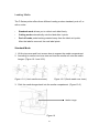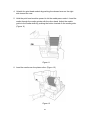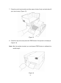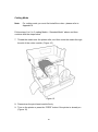
1
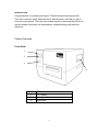
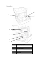
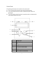
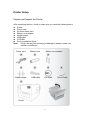
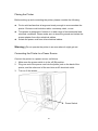
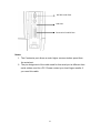
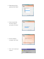
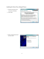
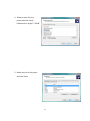
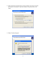
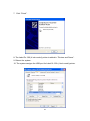
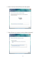
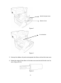
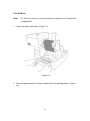
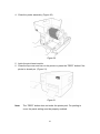
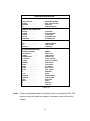
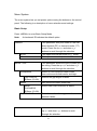
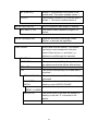
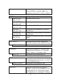
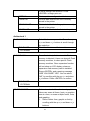
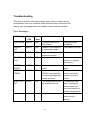
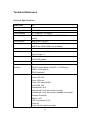
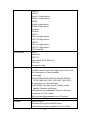
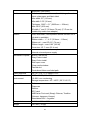
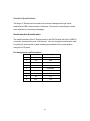
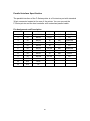
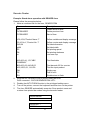
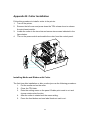
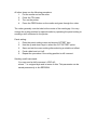
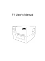
F1 User’s Manual Proprietary Statement This manual contains proprietary information of Argox Information Co., Ltd. It is intended solely for the information and use of parties operating and maintaining the equipment described herein. Such proprietary information may not be used, reproduced, or disclosed to any other parties for any other purpose without the expressed written permission of Argox Information Co., Ltd. Product Improvements Continuous improvement of products is a policy of Argox Information Co., Ltd. All specifications and signs are subject to change without notice. FCC Compliance Statement This equipment has been tested and found to comply with the limits for a Class A digital device, pursuant to Part 15 of the FCC Rules. These limits are designed to provide reasonable protection against harmful interference in a residential installation. This equipment generates, uses, and can radiate radio frequency energy and, if not installed and used in accordance with the instructions, may cause harmful interference to radio communications. However, there is no guarantee that the interference will not occur in a particular installation. If this equipment does cause harmful interference to radio or television reception, which can be determined by turning the equipment off and on, the user is encouraged to try to correct the interference by the following measures: Reorient or relocate the receiving antenna. Increase the separation between the equipment and the receiver. Connect the equipment into a different outlet on a different circuit. Consult the dealer or an experience Radio/TV technician for help. This unit was tested with shielded cables on the peripheral devices. Shielded cables must be used with the unit to insure compliance. The user is cautioned that any changes or modifications not expressly approved by Argox Information Co., Ltd. could void the user’s authority to operate the equipment. Liability Disclaimer Argox Information Co., Ltd. takes steps to assure that the company’s published engineering specifications and manuals are correct; however, errors do occur. Argox Information Co., Ltd. reserves the right to correct any such errors and disclaims any resulting liability. In no event shall Argox Information Co., Ltd. or anyone else involved in the creation, production, or delivery of the accompanying product (including hardware and software) be liable for any damages whatsoever (including, without limitation, damages for loss of business profits, business interruption, loss of business information, or other pecuniary loss) arising out of the use of or the results of use of or inability to use such product, even if Argox Information Co., Ltd. has been advised of the possibility of such damages. 2 A LETTER TO OUR CUSTOMERS Dear Customer, Congratulations on selecting the Argox F Series label printer! You have made an excellent choice. This manual is intended to help you get to know your new printer. There are two parts: an operation guide and a technical reference. In the operation guide there are illustrations to help you quickly learn the functions and features of the printer. Information in greater detail is included in the latter chapters on troubleshooting, maintenance and technical reference. For your convenience much of this information is presented in table format. We hope you enjoy your new printer. Sincerely, Argox Information Co., Ltd. CONTENTS INTRODUCTION ................................................................................................................................... 3 PRINTER OVERVIEW ............................................................................................................................. 3 Front View ..................................................................................................................................... 3 Rear View ...................................................................................................................................... 4 Interior View .................................................................................................................................. 5 CONTROL PANEL................................................................................................................................... 6 CONTROL PANEL BUTTONS ................................................................................................................... 7 Ready Mode .................................................................................................................................. 7 Setup Mode ................................................................................................................................... 7 CONTROL PANEL LIGHTS ...................................................................................................................... 8 PRINTER SETUP .................................................................................................................................. 9 UNPACK AND INSPECT THE PRINTER ..................................................................................................... 9 PLACING THE PRINTER ....................................................................................................................... 10 CONNECTING THE PRINTER TO A POWER SOURCE ............................................................................... 10 SELECTING A COMMUNICATION INTERFACE ........................................................................................ 11 USB Interface Requirements .................................................................................................... 11 Centronics Parallel Interface Requirements ........................................................................... 11 Serial (RS-232) Interface Requirements ................................................................................. 11 COMMUNICATING WITH THE PRINTER ................................................................................................. 13 Before installation ....................................................................................................................... 13 Installing the Driver (Label Dr.200) .......................................................................................... 13 INSTALLING THE PRINTER DRIVER (SEAGULL DRIVER)..................................................................... 16 INSTALLING USB DRIVER (W INDOWS 98 ONLY) .............................................................................. 21 INSTALLING PRINTER DRIVER (W INDOWS 98 ONLY) ........................................................................ 23 USB PLUG AND PLAY FUNCTION ........................................................................................................ 26 INSTALLING THE USB DRIVER IN WINDOWS VISTA (PLUG AND PLAY) ............................................... 29 OPERATIONS ...................................................................................................................................... 33 LOADING A RIBBON ............................................................................................................................ 33 LOADING MEDIA ................................................................................................................................ 37 Standard Mode ........................................................................................................................... 37 Cutting Mode ............................................................................................................................... 40 Peel Off Mode ............................................................................................................................. 42 CONFIGURATION ............................................................................................................................... 45 1 PERFORMING CALIBRATION ................................................................................................................ 45 PRINTING A CONFIGURATION LABEL .................................................................................................. 45 SELECT OR ADJUST THE MEDIA SENSOR ............................................................................................. 47 Select the See-through Sensor ................................................................................................ 47 Adjust the Reflective Sensor .................................................................................................... 47 ADJUST PRINT HEAD PRESSURE ......................................................................................................... 48 SETUP MODE ...................................................................................................................................... 49 Enter Setup Mode ...................................................................................................................... 49 Enter Special Setup Mode ........................................................................................................ 49 How to Leave Setup Mode........................................................................................................ 49 PASSWORD PARAMETERS .................................................................................................................... 50 MENU SYSTEM ................................................................................................................................... 51 Basic Setup ................................................................................................................................. 51 Authorised 1 ................................................................................................................................ 54 Authorised 2 ................................................................................................................................ 57 Special Setup .............................................................................................................................. 58 MAINTENANCE .................................................................................................................................. 60 TROUBLESHOOTING ....................................................................................................................... 61 ERROR MESSAGES .............................................................................................................................. 61 TECHNICAL REFERENCE ............................................................................................................... 62 GENERAL SPECIFICATIONS .................................................................................................................. 62 INTERFACE SPECIFICATIONS ............................................................................................................... 65 Serial Interface Specification .................................................................................................... 65 Parallel Interface Specification ................................................................................................. 66 PS2 Keyboard Interface ............................................................................................................ 67 USB Interface.............................................................................................................................. 67 Auto Polling ................................................................................................................................. 67 APPENDIX A: STAND-ALONE KEYBOARD & BARCODE READER ...................................... 68 KEYBOARD ......................................................................................................................................... 68 Keyboard Functions ................................................................................................................... 68 BARCODE READER ............................................................................................................................. 72 APPENDIX B: CUTTER INSTALLATION ....................................................................................... 74 Installing Media and Ribbon with Cutter ................................................................................. 74 APPENDIX C: DISPENSER INSTALLATION................................................................................. 76 APPENDIX D: SUPER CARD INSTALLATION ............................................................................. 77 2 INTRODUCTION Congratulations on choosing the Argox F Series industrial barcode printer! This user’s manual, which describes the F-Series printer, will help you get to know your new printer. This manual includes a guide to operating the printer as well as related information on maintenance, troubleshooting and technical reference. Printer Overview Front View 1 2 3 4 1 LED indicator 2 LCD display 3 Front panel buttons 4 Media door 3 Rear View 1 2 3 6 4 5 7 1 RS232 Serial Port 2 PS/2 Port 3 USB Port 4 Centronics Parallel Port 5 Power switch (O = Off, I = On) 6 Electronics cover 7 AC power connector 4 Interior View 2 1 3 4 5 6 7 1 Ribbon take-up spindle 2 Media supply hanger 3 Media roll guide 4 Print head module 5 Ribbon supply spindle 6 Media guide 7 Platen roller 5 Control Panel All controls and indicators are located on the control panel. The LCD shows the operation status and printer parameters. The control panel buttons are used to operate the printer and to set parameters. The LED indicators show the printer’s operation status or indicate which control panel buttons are active. 1 2 3 6 4 7 5 8 9 1 POWER light 2 ALERT light 3 LCD 4 MENU button 5 ENTER button 6 UP arrow or PAUSE button 7 LEFT arrow or CANCEL button 8 DOWN arrow button 9 RIGHT arrow or FEED button 6 Control Panel Buttons The printer has six basic control buttons on the control panel. Some of these buttons also work as selection keys. The selectable modes and related functions of the printer key are detailed below. Ready Mode Button Function / Description MENU Enter and exit Setup mode. Press for more than 5 seconds to enter special menu. LEFT The CANCEL key pauses printing. Arrow/CANCEL When printer has an error, press the CANCEL key to return to ready mode after resolving the problem. RIGHT Arrow/FEED The FEED key advances one label when the printer is in stand-by. UP Arrow/PAUSE The PAUSE key temporarily suspends printing. Press CANCEL to resume printing. Setup Mode Button ENTER Function / Description The ENTER key selects the function, item, or displayed value. Save changes and exit Setup mode. LEFT Arrow/CANCEL Scrolls the LCD to the previous parameter. RIGHT Arrow/FEED Scrolls the LCD to the next parameter. UP Arrow/PAUSE Increases the value. Scrolls to the next option. DOWN Arrow Decreases the value. Scrolls to the previous option. 7 Control Panel Lights Light POWER ALERT Status Function / Description On The printer power is turned on. Off The printer power is turned off. Blinking ALERT blinks when an error occurs. 8 Printer Setup Unpack and Inspect the Printer After unpacking the box, check to make sure you have the following items. Printer Power cord An extra ribbon core Ribbon core adaptor Media hanger USB cable CD-ROM Quick Installation Guide Note: If there are any items missing or damaged, please contact your reseller or distributor. Power cord Media hanger Ribbon core USB cable Ribbon core adaptor CD-ROM Printer 9 Quick Guide Placing the Printer Before setting up and connecting the printer, please consider the following: Find a solid surface that is large and sturdy enough to accommodate the printer. Choices could include a table, countertop, desk, or cart. This printer is designed to function in a wide range of environmental and electrical conditions. Please make sure to clear the ground and isolate the power adapter from other electrical cables. Isolate the power cord from other electrical cables. Warning!Do not operate the printer in an area where it might get wet. Connecting the Printer to a Power Source Connect the printer to a power source, as follows: 1. 2. Make sure the power switch is in the off (O) position. Plug one end of the power cord into the power jack on the back of the printer, and the other end of the cord into an AC electrical outlet. 3. Turn on (I) the printer. Power Switch 10 Selecting a Communication Interface This printer comes with a USB interface, a standard Centronics parallel interface, and a nine-pin Electronics Industries Association (EIA) RS-232 serial data interface. USB Interface Requirements The Universal Serial Bus (USB) interface is version 2.0 and 1.1 compliant and provides a full-speed (12Mb/s) interface that is compatible with your existing PC hardware. The USB’s ―plug and play‖ design makes installation easy. Multiple printers can share a single USB port/hub. Centronics Parallel Interface Requirements You can connect the printer to the host computer’s parallel port using any standard Centronics cable. The required cable must have a standard 36-pin parallel connector on one end, which is plugged into the parallel port located on the back of the printer. The other end of the parallel interface cable connects to the printer connector at the host computer. For pin-out information, please refer to the Technical Reference in this manual. Serial (RS-232) Interface Requirements The required cable must have a nine-pin "D" type male connector on one end, which is plugged into the mating serial port located on the back of the printer. The other end of the cable connects to a serial port on the host computer. For technical and pin-out information, please refer to the Technical Reference in this manual. 11 RS-232 Serial Port USB Port Centronics Parallel Port Notes: 1. The Centronics port allows a much higher communication speed than the serial port. 2. The pin assignment of the cable used for this serial port is different than serial cables used for a PC. Please contact your local Argox reseller if you need this cable. 12 Communicating with the Printer The bundled printer driver can be applied to all applications under Windows 98/2000/2003/Windows XP and Windows Vista. With this driver you can run any popular Windows software applications such as MS-Word and print to this printer. Before installation 1. Check the contents of the driver to ensure it is completed. 2. Make a backup copy of the driver. Installing the Driver (Label Dr.200) 1. Double click the driver file (Label Dr. 200) to execute in Windows. 2. Click "Next". 3. Select a driver for your printer and click "Next". For F1, you should select Argox F1(203 dpi). 13 4. Select the port of the printer and click "Next". 5. When the related files have been copied to your system, click ―Next‖. 6. After the installation is complete, click ―Finish‖. 7. Click ― Yes‖ to restart your computer. 14 Notes: 1. If you are updating the driver, make sure the previous version has been removed. 2. If you install new bar code application software such as ArgoBar, LabelView or CodeSoft, you should activate the Label Dr. 200 driver and set it as the current printer driver. 3. If you install new bar code application software such as Bartender Ultra Lite, you should activate the seagull driver for Argox printers. 15 Installing the Printer Driver (Seagull Driver) 1. Double click the driver file to execute in Windows. 2. Click "Next". 3. Select ‖Install printer drivers‖ and click ―Next‖. 16 4. Select a driver for your printer and click "Next" . Please select ―Argox F1 PPLB‖. 5. Select the port of the printer and click "Next. 17 6. Enter a specify Printer Name ―Argox F1 PPLB‖ and click ―Next‖ 7. Click ―Finish‖ to complete the installation. 18 8. After the related files have been copied to your system, click ―Finish‖ 9. After the installation is completed, click ―Close‖ 19 Notes: 4. If you are updating the driver, make sure you remove the previous version first. 5. If you install new bar code application software such as ArgoBar, LabelView or CodeSoft, you should activate the Label Dr. 200 driver and set it as the current printer driver. 6. If you install new bar code application software such as Bartender Ultra Lite, you should activate the seagull driver for Argox printers. 20 Installing USB Driver (Windows 98 Only) Note: Uninstall the printer driver before installing the USB driver. 1. Connect the label printer to a computer with a USB cable. 2. Turn on the printer’s power. 3. The window ―Add New Hardware Wizard‖ will pop, click ―Next‖. 4. Select ‖Search for the best driver for your device. (Recommended)‖, click ―Next‖. 5. Select new driver location, Click‖ Next‖ 21 6. Click ― Next‖ 7. Click ― Finish‖ 8. Click ― Next‖ Note: After the USB driver is installed, you could refer to next page to install the printer driver. 22 Installing Printer Driver (Windows 98 Only) 9. Select‖ Search for the best driver for your device‖ ( Recommended)‖. 10. Click‖ Next‖ 11. Select‖ Specify a location‖ 12. Click‖ Browse‖ and choose Label Dr. 200 location. 13. Select― Win98‖ 14. Click‖ OK‖ 23 15. Click‖ Next‖ 16. Click‖ Next‖ 17. Click‖ Finish‖ 18. Click‖ Finish‖ 24 19. Click‖ OK‖ 25 USB Plug and Play Function Note: The printer driver needs to be installed with version 1.4.00 or later and support ―USB Plug and Play‖ for Windows XP, Windows 2003 and Windows 2000. 1. Extract the PrinterDriver.exe to the fixed route. (―C:\Label Dr. 200‖, for example) 2. Connect the label printer to a computer with an USB cable. 3. Turn on the printer’s power and the system will detect the device automatically. 4. Select ―Install from a list or specific location (Advanced)‖, click ―Next‖. 26 5. Select ―Search for the best driver in these locations‖ and choose ―Include this location in the search‖. Input the location of the printer driver, click ―Next‖. 6. Select ―Continue Anyway‖. 27 7. Click ―Finish‖. 8. The Label Dr. 200 (4 inch model) printer is added in ―Printers and Faxes‖. 9. Reboot the system. 10. The system assigns the USB port for Label Dr. 200 (4 inch model) printer. 28 Installing the USB Driver in Windows Vista (Plug and Play) 1. Extract the PrinterDriver.exe to the fixed route. (―C:\Label Dr. 200‖, for example) 2. Connect the label printer to a computer with an USB cable. 3. Turn on the printer’s power and the system will detect the device automatically. 4. Select ―Locate and install driver software (recommended)‖. 5. Pop the window ―User access control‖ and click ― Continue‖ 29 6. Select ―I don’t have the disk. Show me the other options.‖ 7. Select ―Browse my computer for driver software (advanced) ―. 30 8. Input the location of printer driver. (―C:\Dr200 Printer Driver_ x86\Win Vista\4 inch mode‖, for example) 9. Select‖ Install this driver software anyway‖ 10. The related files start to copy to your system. 31 11. After the installation is complete, click ―Close‖. 32 Operations Loading a Ribbon Note: The F-Series printer uses transfer thermal printing and the required ribbon is coated outside. 1. Lift the top cover and front access door to expose the media compartment. (Figure 1) Figure 1 2. Unlatch the print head module by pushing the release lever on the right side toward the rear. (Figures 2 & 3) 33 Media Compartment Release Lever Figure 2 Print Module Figure 3 3. Unwrap the ribbon roll pack and separate the ribbon roll and the bare core. 4. Attach the edge of the ribbon to the bare core and wind a little bit onto the core. (Figure 4 & 5) Figure 4 34 Figure 5 5. Insert the ribbon roll into the supply holder. First snap in the right side and then left side. Make sure the coating side of the ribbon is face down. (Figure 6) Ribbon Supply Holder Figure 6 6. Put the print head module down and insert the bare core into the pick-up holder. (Figure 7-1) First snap in the right side and then left side. (Figure 7-2) Ribbon Pick-up Holder Figure 7-1 Figure 7-2 35 7. Turn the wheel of the print head module to ensure the ribbon is tightly wound. (Figure 8) Wheel Figure 8 8. Press down the print head module firmly on both sides till you hear a snap. (Figure 9) Figure 9 36 Loading Media The F-Series printer offers three different loading modes: standard, peel-off, or with a cutter. Standard mode allows you to collect each label freely. Cutting mode automatically cuts the label after it prints. Peel-off mode peels backing material away from the label as it prints. After the label is removed, the next label prints. Standard Mode 1. Lift the top cover and front access door to expose the media compartment. 2. According to media core inner size and load the media roll onto the media hanger. (Figure 10-1 and 10-2) Figure 10-1 (1inch media core inner) Figure 10-2 (3inch media core inner) 3. Click the media hanger back into the media compartment. (Figure 10-3) Media Hanger Figure 10 37 4. Unlatch the print head module by pushing the release lever on the right side toward the rear. 5. Hold the print head module upward to let the media pass under it. Lead the media through the media guides with the other hand. Adjust the media guide to the media width by pushing the button located on the media guide. (Figure 11) Figure 11 6. Lead the media over the platen roller. (Figure 12) Figure 12 38 7. Close the print head module and then press it down firmly on both sides till you hear a snap. (Figure 13) Figure 13 8. Close the top cover and press the FEED button if the printer is already on. (Figure 14) Note: After the media is loaded, you could press FEED button to calibrate the media length. Figure 14 39 Cutting Mode Note: For cutting mode you must first install the cutter—please refer to Appendix A. Follow steps 1 to 6 in ―Loading Media – Standard Mode‖ above and then continue with the steps below. 7. Thread the media over the platen roller, and then route the media through the slot of the cutter module. (Figure 15) Figure 15 8. Press down the print head module firmly. 9. Turn on the printer or press the ―FEED‖ button if the printer is already on. (Figure 16) 40 Figure 16 Note: The ―FEED‖ button does not make the printer cut. For cutting to occur the panel setting must be properly enabled. 41 Peel Off Mode Note: 1. For Peel-off mode you must first install the dispenser kit. Please refer to Appendix B. Open the peeler assembly. (Figure 17) Figure 17 2. Remove approximately 6-inches of labels from the backing paper. (Figure 18) 42 Figure 18 3. Lead the backing paper over the platen roller, and then thread it back into the slot. Make sure that the media is under the peeler module. (Figure 19) Figure 19 43 4. Close the peeler assembly. (Figure 20) Figure 20 5. Latch the print head module. 6. Close the top cover and turn on the printer or press the ―FEED‖ button if the printer is already on. (Figure 21) Figure 21 Note: The ―FEED‖ button does not make the printer peel. For peeling to occur the panel setting must be properly enabled. 44 Configuration This section discusses calibration, printer configuration settings and shows you how to view or change printer parameters through the control panel. Performing Calibration After the media is loaded, you should perform a media calibration to calibrate the media sensor. During the calibration, the printer determines the label length and the sensor settings. The results of the auto calibration are stored in the printer’s memory and are retained even when the printer power is off. These parameters remain in effect until you perform the next calibration. 1. Press<MENU> to enter setup mode. 2. Use the left <←> and right <→> buttons to scroll through the parameters until you reach MEDIA CALIBRATION. 3. Press<ENTER> 4. Press<MENU> to SAVE CHANGES 5. Use the up <↑> and down < ↓> buttons to scroll to YES or NO. 6. Press<ENTER> Printing a Configuration Label After loading the media or performing a self-test, print a configuration label as a record of your printer’s current settings. Keep the label to use when troubleshooting printing problems. To print a printer configuration label, complete the following steps: 1. Press <MENU> to enter setup mode. 2. Use the left <←> and right <→> buttons to scroll through the parameters until you reach PRINT OUT. 3. Press<ENTER> 4. Use the up <↑> and down < ↓> buttons to scroll to SETTING. 5. Press <ENTER> to print the configuration label. (Figure 22) 45 PRINTER CONFIGURATION VERSION INFORMATION: PPLB F1B0-1.00 . . . . . . . 032408 . . . . . . . . . . . . . . . 80320001 . . . . . . . . . . . . . 1.1 . . . . . . . . . . . . . . . . . . FIRMWARE VERSION DATE CODE (mmddyy) SERIAL NO EEPROM VERSION MEMORY INFORMATION : 8192 KB . . . . . . . . . . . . . 6088 KB . . . . . . . . . . . . . 4096 KB . . . . . . . . . . . . . 3071 KB . . . . . . . . . . . . . ONBOARD . . . . . . . . . . TOTAL RAM AVAILABLE RAM TOTAL FLASH AVAILABLE FLASH FLASH MODULE PARAMETERS INFORMATION: 1M ................ 13 . . . . . . . . . . . . . . . . . . . ENGLISH . . . . . . . . . . . . PRINTED LENGTH LABEL COUNT LANGUAGE SETTING INFORMATION : TRANSFER THERMAL GAP / NOTCH . . . . . . . . 79 MM . . . . . . . . . . . . . . TRANSMISSIVE . . . . . . 1 ( CENTER ) . . . . . . . . . 12 INCH . . . . . . . . . . . . . NORMAL . . . . . . . . . . . . 0 MM . . . . . . . . . . . . . . . 0 MM . . . . . . . . . . . . . . . 0 MM . . . . . . . . . . . . . . . 0 MM . . . . . . . . . . . . . . . 8................... 3 IPS . . . . . . . . . . . . . . . . ENABLED . . . . . . . . . . . ENABLED . . . . . . . . . . . 9600 . . . . . . . . . . . . . . . . NONE . . . . . . . . . . . . . . . 8................... 1................... RIBBON MEDIA TYPE LABEL LENGTH SENSOR TYPE TRANS. SENSOR MEDIA CAL LENGTH PRINT MODE TEAR OFFSET CUT OFFSET HORI. OFFSET VERT. OFFSET DARKNESS SPEED REPRINT MODE ALERT BUZZER BAUD RATE PARITY DATA BITS STOP BIT Figure 22 Note: Printer configuration label is activated via the control panel LCD. The options to print the label are located in the basic setup of the menu system. 46 Select or Adjust the Media Sensor This printer uses two types of media sensors: See-through and reflective. The default is see-through sensor No 1. Select the See-through Sensor The standard see-through sensor is in a fixed position and enabled from the control panel. (Figure 23) Figure 23 Adjust the Reflective Sensor 1. Press down the Thermal Print Head (TPH) release lever to release the print head module. 2. Lift the print head module to expose the media sensor cover. (Figure 24) 3. Slide the media sensor until the reflective sensor aligns with the gap or notch. (Figure 25) Figure 24 Figure 25 47 Adjust Print Head Pressure If printing quality is not even, you may need to adjust the print head pressure. To adjust print head pressure use a flat tip screwdriver to turn the left and right screws counterclockwise to increase the pressure, or clockwise to decrease the pressure. (Figure 26) Left Screw Right Screw Figure 26 Adjust the pressure adjustment screws as follows: Condition Resolution Print quality of the left side of a label Turn the left screw counterclockwise to is too light. increase the pressure. Print quality of the right side of a label is too light. Turn the right screw counterclockwise to increase pressure. 48 Setup Mode You can set printer parameters for your application directly by using the control panel LCD and buttons. Enter Setup Mode 1. 2. Press <MENU>. Use the left or right button to scroll through the parameters. Enter Special Setup Mode Special setup mode is the menu that lets you set up the language and change password. 1. Press the <MENU> button for more than 5 seconds and release. 2. Use the left or right button to scroll through the parameters. How to Leave Setup Mode 1. Press <MENU>. 2. The printer displays SAVE CHANGES and activates the <ENTER> button. The following table shows three options for leaving the setup mode. Option Description Save Changes Press <ENTER> to save changes and exit setup mode. Reject Changes Press the up <↑> and down < ↓> buttons to select ―NO‖, and press <ENTER>. The printer rejects changes and exits setup mode. Return to Setup Mode Press <MENU> to return to the same parameter. Press the left <←> button to return to the previous parameter 49 Password Parameters The F-Series printer has three password levels. When you enter the setup mode on the control panel, parameters which are not protected by password are displayed. You must enter a correct password to enter AUTHORISED SETUP 1 and AUTHORISED SETUP 2. The password levels and default passwords are shown in the following table. Password Level Level name Default Password 3 AUTHORISED SETUP 2 9999 2 AUTHORISED SETUP 1 1234 1 BASIC SETUP No password To enter a password when prompted, complete the following steps: 1. When the printer displays AUTHORISED SETUP X, press <ENTER>. The LCD displays password and the number 0000. 2. Enter the four-digit password for the password level displayed or for a higher level. The left <←> and right <→> buttons select the digit position. The up <↑> and down <↓> buttons change the selected digit’s value. 3. After entering the password, press <ENTER>. 50 Menu System The menu system lets you set printer options using the buttons on the control panel. The following is a description of menu selections and settings. Basic Setup Press <MENU> to enter Basic Setup Mode A checkmark indicates the default option. Note: RIBBON This parameter sets print mode for use with direct thermal (DT) or thermal transfer (TT) mode. Press the up <↑> and down <↓> buttons to scroll through the selection. YES This option sets as the printer to TT mode. NO This option sets as the printer to DT mode. MEDIA TYPE Gap/Notch This parameter shows the type of media you are using. Press the up <↑> and down <↓> buttons to scroll through the selection. Select for non-continuous web media, non-continuous fanfold media, and tags. GAP LENGTH 10mm (10~99) MARK MARK THICKNESS 10mm (10~99) CONTINUOUS TRANSMISSIVE Selects the gap length of labels. Non-continuous black mark lines. Select black mark thickness of labels Select for media without gaps or divisions between labels. Select transmissive sensor 1 or 2. Press the up <↑> and down <↓> buttons to scroll through the selection. 51 1 (CENTER) Sensor 1 is positioned in the center of the media route. This option enables sensor 1. 2 (LEFT) MEDIA CAL LENGTH 12 INCH (1~30) The position of sensor 2 is to the left side of sensor 1. This option enables sensor 2. Set the maximum label length to calibrate. The default media calibration length is 12 inches. MEDIA CALIBRATION Calibrate and detect media gap. Press <Enter> to activate this operation. PRINT MODE Setup label removal method. The method you select must correspond to the print mode. Press the up <↑> and down <↓> buttons to scroll through the selection. NORMAL TEAR OFF This parameter establishes the position of the labels over the tear-off bar after printing. PEEL OFF Enables label peeler mode. CUT The printer automatically cuts a label after it is printed. BY COMMAND Sets a specific number of labels for cutting by command. CUT AFTER BATCH The printer waits to cut after the number of labels you set in BATCH COUNT. BATCH COUNT Sets the number of labels for BATCH CUT. 0001 (1~9999) BATCH CUT The printer waits to cut after the number of labels you set with ―P‖ command to the printer. SINGLE CUT Sets cut after one label 52 ROTATE CUTTER This parameter allows you to rotate cutter. Press <ENTER> to activate. Note: The parameter shows only if a cutter is installed. OFFSET This option fine tunes the media stop location TEAR OFFSET 0mm (-3~+3) Sets label tear off offset. PEEL OFFSET 0mm (-16~+16) Sets label peeling offset. CUT OFFSET Sets label cutting offset. 0mm (-16~+16) VERTICAL 0mm (-30~+30) Change the vertical position of the whole label format. HORIZONTAL 0mm (-99~+99) Change the horizontal position of the whole label format. TPH OFFSET 0mm (-3~+3) Change the thermal print head (TPH) vertical offset. PRINT WIDTH 102mm (10~104mm) DARKNESS 8 (1~15) SPEED 3IPS (1~6 IPS) PRINT OUT Sets maximum print width. Objects that exceed the maximum print width do not print. The print width default value is 10mm. Adjusts print darkness for consistent high quality printing. Press up <↑> to increase value or down<↓> to decrease value. The default for print darkness is 8. Controls the rate of label movement during the printing process. Press up <↑> or down <↓> to choose the value. The default for print speed is 3 ips. Prints out current printer configuration settings, or prints out downloaded form list, downloaded font list, downloaded graphic list. Press the up <↑> and down <↓> buttons 53 to scroll through the selection. Press <ENTER> to begin print out. SETTING Prints a printer configuration label. FORM LIST Prints a label that lists the form currently stored in the printer. GRAPHIC LIST Prints a label that lists the graphics currently stored in the printer. FONTS LIST Prints a label that lists the fonts in the printer. Authorised 1 FLASH MODULE ONBOARD Select flash memory module. Press the up <↑> and down <↓> buttons to scroll through the selection. The default is internal flash module. EXTERNAL CLEAR FLASH Erase flash data (all data stored in Flash memory is deleted.) Users can clear all Flash memory modules, or clear specific Flash memory modules. Clear expansion function will not show on LCD display unless an expansion flash memory card is installed. Press <ENTER> and a warning message ―ARE YOU SURE? YES‖. You can select ―NO‖ by scrolling with the up <↑> and down <↓> buttons. Press <ENTER> to confirm. ONBOARD EXTERNAL DELETE OBJECT Delete downloaded form, font, and graphic. Users can erase all forms, fonts, or graphics one at a time, or erase multiple forms, fonts, and graphics. 1. Select Delete form, graphic or font by scrolling with the up <↑> and down <↓> buttons. 54 2. 3. Press <ENTER> and use the up <↑> and down <↓> buttons to scroll through selections. Press <ENTER> again and a warning message ―Are you sure‖ appears. You can select ―YES‖ to continue or ―NO‖ to cancel this operation. FORM Delete form. GRAPHIC Delete graphic. FONT Delete font. AUTO FORM Auto form lets you detach the printer from a computer and print in standalone mode. OFF Enable automatic form printing. ON Disable automatic form printing. REPRINT MODE Reprint a label partially printed due to ribbon out, media out or head open error conditions. The label is reprinted after error condition is corrected. On Enable recovery print. Off Disable recovery print. LABEL COUNT The printer displays label quantity you print. On Enables the label count. Off Disables the label count. LABEL COUNT TYPE Decreasing Increasing ALERT BUZZER Count printing label quantity as decreasing or increasing. Count printing label as decreasing. Count printing label as increasing. Audible signal indicates error condition. ON Enables the buzzer. OFF Disables the buzzer. 55 HEX DUMP The hex dump mode is a troubleshooting tool for checking the interconnection between the printer and the host computer. Select ―ON‖ and all transmitted data is dumped and printed as ASCII and Hex values. OFF Normal operating mode. ON Prints raw ASCII data received from the host. SERIAL COMM. Baud Rate 9600bps Sets serial port communication. Determines the RS-232 baud rate. The default baud rate is 9600bps. (1200~115200bps) PARITY The parity of the printer must match the parity of the host computer for accurate communications to take place. None No parity. Odd Odd parity. Even Even parity. DATABITS Set the Data Bit to match the setting used by the host computer. 7Bits Seven bit Word length. 8Bits Eight bit Word length. STOPBIT Define Stop Bit. 1 One stop bit. 2 Two stop bits. HANDSHAKE BOTH Define handshake protocol between printer and host. Use both handshaking methods. XON/XOFF CTS/RTS FINE DARKNESS Fine-tunes darkness based on current main darkness level. 0 (-63~+63) BASE SPEED The default fine darkness is 0. Sets the base print speed. The real print speed is main speed plus base speed. 56 0 (0~4ips) LOAD DEFAULT The default of base speed is 0. Reset Printer and panel settings. Press <ENTER> and a warning message ―ARE YOU SURE? YES/CONFIRM‖ appears. Select with the up <↑> and down <↓> buttons. Press <ENTER> to confirm. Authorised 2 RTC SETUP This function appears on the LCD display only when the RTC module is installed. Press <ENTER> and press the right <→> button to move to the next digit. Use the up <↑> and down <↓> buttons to select a value. Press <ENTER> to accept the value. (Note: This parameter only appears if the RTC card is installed.) DATE (MM-DD-YY) Change current date if RTC module is installed. Format: MM-DD-YY TIME (HH:MM:SS) Change current time if RTC module is installed. Format: HH:MM:SS ADVANCED CUT Enable or disable backfeed after label cut. This function does not appear if cutter function is disabled. (Note: This parameter appears only if cutter is installed.) WITH BACKFEED Enable backfeed after cut. W/O BACKFEED Disable backfeed after cut. ADVANCED PEEL Enable or disable backfeed after a label is peeled and removed. (Note: This parameter only appears if peeler is installed.) WITH BACKFEED Enable backfeed after peel. W/O BACKFEED Disable backfeed after peel. 57 IGNORE COMMAND Set panel commands to be active or ignored. In default, all commands are active. SELECT ALL DARKNESS SPEED RIBBON DETECT MEDIA TYPE PRINT MODE PRINT WIDTH SERIAL COMM. RTC SETUP Special Setup LANGUAGE The LANGUAGE parameter is included in the special menu. You can select a language via the control panel. 1. Press <MENU> for 5 seconds. 2. Press the <↑> or <↓> button to reach the language of your choice. 3. Press <MENU> and you are prompted to accept changes. Press <ENTER> to confirm the language. ENGLISH FRENCH GERMAN ITALIAN SPANISH PORTUGUESE CHANGE PASSWORD The parameter allows you to change the password for Authorised 1 and Authorised 2. 1. Press <MEN 2. .U> for 5 seconds. 3. Press <ENTER> and the printer prompts 58 you to enter the old password. 4. 5. Press <ENTER> again and the printer prompts you to enter the new password. Press <MENU> and the printer prompts you to accept changes. SETUP 1 The default password is 1234. SETUP 2 The default password is 9999. 59 Maintenance Argox recommends using following material to clean the printer: 100% ethanol Cotton swab Blower brush CAUTION! 1. The print head gets hot and could cause severe burns. Always allow the print head to cool before maintenance. 2. Argox is not responsible for damage caused by the use of cleaning fluids on this printer. Component Procedure Frequency Print head 1. Open the print head and remove the media and ribbon. 2. Using the swab and 100% ethanol, wipe the print head from end to end. Clean the print head after each change of ribbon. Platen roller Manually rotating the platen roller, clean it thoroughly with 100% ethanol and swab. Clean the platen roller when changing a new label roll. Tear-off/Peel-off bar Use the swab to remove excess adhesive from the tear-off/peel-off bar. Once a month. Sensor Air blow or vacuum. Once every six months. 60 Troubleshooting This section provides information about errors that you might need to troubleshoot. If an error condition exists with the printer, review the LCD display error messages below for possible causes and the solutions. Error Messages LCD Display Blinking Buzzer LED Possible Cause Solution alert HEAD OPEN ALERT YES The print head is not fully closed. Close print head completely. RIBBON OUT ALERT YES Ribbon is not loaded or is incorrectly loaded. Load ribbon correctly. MEDIA OUT ALERT YES Media is not loaded or is Load media correctly. loaded incorrectly. MEMORY FULL ALERT YES Memory is full. Delete data in the memory or expand the memory. CUTTER ALERT YES Media is jammed in the Remove the jammed cutter. paper. FAILED SERIAL IO ERROR ALERT YES Format or baud rate of RS232 communication is inconsistent between printer and host. Check the baud rate, format or protocol between host and printer. HEAD TOO HOT ALERT YES The temperature of the print head is too hot. Let the printer cool down. Printing will resume when the print head cools to a suitable temperature. PAUSE ALERT NO The printer is paused. Press the CANCEL button once to resume. 61 Technical Reference General Specifications Model name F1 Printing method Direct Thermal / Thermal Transfer Printing resolution 203 dpi (8 dots/mm) Printing speed 2 ~ 6 ips (50 ~152 mm/s) Printing length 0.5‖ ~ 90‖ (13mm ~ 2286mm), MAX 90‖(Command mode) Printing width Max 4.09‖ (104 mm) Memory 8MB DRAM (7MB user available) 4MB Flash ROM (3MB user available) CPU type 32 bit RISC microprocessor Media sensor Reflective (movable) See-through x 2 Display LED indicators x 2 2x16 LCD display Operation interface Button x 6 Communication Centronics parallel interface RS-232 serial (baud rate 2400 ~ 115200 bps) USB 2.0 (full speed) PS/2 Keyboard 1D Barcodes PPLB: Code 128 UCC Code 128 auto Code 128 subset A/B/C UCC/EAN 128 Interleaved 2 of 5 Interleaved 2 of 5 with check sum digit Interleaved 2 of 5 with human readable check digit German Postcode Matrix 2 of 5 UPC Interleaved 2 of 5 Code 39 Code 39 with check sum digit 62 Code 93 EAN-13 EAN-13 2 digit add-on EAN-13 5 digit add-on EAN-8 EAN-8 2 digit add-on EAN-8 5 digit add-on Codabar Postnet UPC-A UPC-A 2 digit add-on UPC-A 5 digit add-on UPC-E UPC-E 2 digit add-on UPC-E 5 digit add-on GS1 Data Bar 2D Barcodes PPLB: Maxicode PDF-417 Data Matrix (ECC 200 only) QR code Composite code Fonts Internal character sets standard 5 alpha-numeric fonts with height from 0.049‖~0.23‖ 20 codepages for 8-bits character (code page 437,850,852,860,863,865,857,861,862,855,866 737,851,869,1250,1251,1252,1253,1254,1255 ) 9 codepages for 7-bits character (USA, British, German, French, Danish, Italian Spanish, Swedish and Swiss ) Internal fonts are expandable up to 24x 24 times 4 direction 0º~270º rotation Soft fonts are downloadable (up to 72 points) Graphic PCX bitmap, GDI , Binary raster Software ARGOX PPLB Windows Driver (Win 2000/XP/Vista) Label editing software-ArgoBar Pro/ Print Utility/ 63 Bartender/ Font Utility Media Roll-feed, die-cut, continuous, fan-fold, tags, thermal ticket, plain paper and fabric label Max width 4.3‖ (110 mm) Min width 0.79‖ (20 mm) Thickness .0025‖~. 01‖ (.0635mm ~. 254mm) Max OD 8‖ (203 mm) ID width 1‖ and 3‖ (25.4mm~76 mm) (3‖ ID can be installed by media core adapter) Ribbon Wax, Wax/Resin, Resin(Ribbon wound ink-side out or ink-side in available) Ribbon width – 1.‖~ 4.3‖ (25.4mm ~ 110mm) Ribbon roll – max OD 2.9‖ (74 mm) Ribbon length – max 1182’ (360 M) Core size - ID 1‖ core (25.4 mm) Power Source 100~ 240VAC , 50-60Hz, 5Amps Internal universal power supply Mechanism request Built-in Tear off bar Easy Peeler install Easy Cutter install Side-open cover Clear media window Fanfold slot Centralized ribbon and label path Safety Approval CE, UL, CUL, FCC class A, CCC Operation environment 40ºF ~ 104ºF (4ºC~40ºC) 10~90% non condensing Storage temperature -4ºF~140ºF (-20 ºC~60 ºC) Optional items Cutter Dispenser Stacker RTC card 4MB Asian Font card (Simply Chinese, Tradition Chinese, Japanese, Korean) Standalone KDU – ArgoKee Compact size W390 X L309 X H255 mm Weight 16.5 lbs (7.5 kgs) 64 Interface Specifications The Argox F-Series printer sends and receives messages through serial, parallel and USB communication interfaces. The printer automatically checks each interface for incoming messages. Serial Interface Specification The serial interface of the F-Series printer is an RS-232 port with 9-pin (DB9-S) connector located at the rear of the printer. You can change the baud rate; data bit, parity bit and stop bit by both sending commands to the printer and by using the LCD panel. Pin Assignment and Description Pin No. Direction 1 Description Shorted to Pin-6 2 IN RxD 3 OUT TxD 4 N.C. 5 GROUND 6 Shorted to Pin-1 7 OUT RTS 8 IN CTS 9 OUT +5V 65 Parallel Interface Specification The parallel interface of the F-Series printer is a Centronics port with standard 36-pin connector located at the rear of the printer. You can connect the F-Series printer and the host controller with a standard parallel cable. . Pin Assignment and Description Pin No. Direction Description Pin No. Direction 1 IN /STROBE 13 OUT SELECT 2 IN DATA 1 14,15 ----- N.C. 3 IN DATA 2 16 OUT GROUND 4 IN DATA 3 17 OUT GROUND 5 IN DATA 4 18 ----- N.C. 6 IN DATA 5 19~30 OUT GROUND 7 IN DATA 6 31 ---- N.C. 8 IN DATA 7 32 OUT /FAULT 9 IN DATA 8 33~36 ---- N.C. 10 OUT /ACK 11 OUT BUSY 12 OUT PE 66 Description PS2 Keyboard Interface The Argox F-Series printer provides a standard IBM PC PS2 keyboard interface that lets you control the printer with a standard PS2 keyboard. Pin Assignment and Description The PS2 keyboard interface is a female, 6-pin, mini DIN connector. Pin No. Direction Description 1 ----- N.C. 2 OUT +5V 3 ----- N.C. 4 IN/OUT DATA 5 GROUND 6 IN/OUT CLOCK USB Interface The Argox F-Series printer provides a standard USB interface that conforms to USB 2.0 full-speed specification. This increases the data transfer rate between the host controller and printer, dramatically enhancing performance. Pin Assignment and Description Pin No. Direction Description 1 IN Vcc(+5V) 2 IN/OUT Differential + 3 IN/OUT Differential - 4 GROUND Auto Polling Both the serial port and parallel port of this printer can be active at the same time, i.e. the printer can simultaneously communicate with two PCs via different ports. Note that there is no port contention, so if both PCs transmit data at the same time data may become damaged in the receiving buffer. 67 Appendix A: Stand-alone Keyboard & Barcode Reader This appendix covers stand-alone operation with keyboard or barcode reader. Keyboard To use the printer in stand-alone operation with a keyboard, please follow the procedure described below: 1. 2. Press the MENU key to enter menu mode on the LCD panel. Enter a password to switch to privileged menu and enable the AUTO 3. 4. 5. 6. 7. 8. 9. FORM function. Save the changes and press MENU again to leave the settings menu. Make a form for the keyboard. Download a form to the printer and save it to flash memory permanently. Turn off the printer. Connect the keyboard to the keyboard interface. Turn on the printer. Select your form and press enter to confirm, or change the form by pressing up and down. 10. Type the input data according to instructions in the first row of the LCD. Keyboard Functions Key Function ESC 1. Go back to the previous variable input field. 2. During data input level, press <ESC> or the CANCEL key on the panel for more than 5 seconds to force the printer back to the select form level. Users can change to other forms here and press enter to start the form. 3. In select form level, press <ESC> or the CANCEL key on the panel for more than 5 seconds to force the Backspace printer to exit standalone mode and switch back to normal printing. However, you must still disable AUTO FORM in the settings menu. Otherwise it begins in stand alone mode when the printer restarts. Deletes the first character to the left of the cursor and shifts all characters on the right forwards. 68 Insert Inserts a new character at the cursor position. Shift Switches between upper/lower case characters as the shift key is pressed. Delete Deletes the character at the cursor and shifts all the characters on the right forwards. Caps Lock Switches to upper case characters. Space Moves the cursor to right. Home Moves the cursor to the leftmost position. End Moves the cursor to the rightmost position. Example: Stand alone operation with keyboard form Please follow the procedure below: 1. Make a command file for the form, KBD.FRM 2. 3. Command Description ZS FK"KBDFORM" FS"KBDFORM" Enable store to flash Delete previous form Start of form V00,15,N,"Product Name ?" C0,10,N,+1,"Product No. ?" Define variable and display message Define counter and display message Q50,24 q406 S2 D8 ZT Set label dimension Set label width Set printing speed Set printing darkness Print from top A50,20,0,4,1,1,R,‖ABC COMPANY‖ B50,60,0,2,2,4,40,B,C0 A50,150,0,3,1,1,N,V00 Print fixed data FE ZN End of form Disable store to flash Print barcode I25 for counter Print the input product Send the file, KBD.FRM to printer under MS-DOS DOS command : COPY/B KBD.FRM LPT1: Enable the AUTO FORM function in the privileged settings menu. 69 4. Turn off the printer, connect the keyboard and then turn on the printer. 5. The LCD displays this message: SELECT FORM KBDFORM 6. 7. Use the up and down keys to select another form and press <ENTER> to confirm. Once a form is selected, the LCD displays: LOADING FORM KBDFORM 8. Key-in the input device and barcode data. Product Name? Barcode Printer Product No. ? 0123456789 9. Input the label count and the copy count. LABEL SET NO. ? 2 COPIES PER LAB. ? 3 10. Six labels are printed out and the printer goes to step 8 and waits for data input. 70 Output 71 Barcode Reader Example: Stand alone operation with READER form Please follow the procedure below: 1. Make a command file for the form, READER.FRM 2. 3. 4. 5. Command Description ZS FK"READER" FS"READER‖ Enable store to flash Delete previous form Start of form V00,15,N,"Product Name ?" C0,10,N,+1,"Product No. ?" Q50,24 Define variable and display message Define counter and display message Set label dimension q406 S2 D8 ZT Set label width Set printing speed Set printing darkness Print from top A50,20,0,4,1,1,R,‖ABC COMPANY‖ B50,60,0,2,2,4,40,B,C0 Print fixed data A50,150,0,3,1,1,N,V00 PA1 FE ZN Print the input product Single copy End of form Disable store to flash Print barcode I25 for counter Send the file, READER.FRM to printer under MS-DOS DOS command : COPY/B READER.FRM LPT1: Disable the AUTO FORM function in the privileged setting menu. Turn off the printer, connect the keyboard and then turn on the printer. The form READER automatically executes. Scan product name and number from printed bar codes using the barcode reader. Product Name? Apple Product No. ? 11223344 72 6. A label is printed. The copy count depends on the PA command for the READER form. Step 4 repeats automatically. Output Notes: 1. 2. 3. To return to normal operation, press and hold <ESC> on keyboard or the CANCEL key for more than 5 seconds. During standalone operation, you can input data through: Keyboard Barcode reader Parallel port Serial port USB For the keyboard form the P command is not allowed, while for the barcode reader/ scanner form, a PA command must be included. 73 Appendix B: Cutter Installation Follow this procedure to install a cutter in the printer. 1. Turn off the printer. 2. Remove the left cover and press down the TPH release lever to release the print head module. 3. Locate the cutter in the two slots and secure two screws indicated in the figure below. 4. Turn on the power switch and enable the cutter from the control panel. Installing Media and Ribbon with Cutter The first time after installation or after a cutter jam use the following procedure: 1. Put the media end on the roller. 2. Close the TPH latch. 3. Enter the setting menu on the panel. Enable print mode to cut and 4. 5. choose rotate cutter function. After the cutter is rotated exit the menu setting. Press the feed button and one label feeds out and is cut. 74 All other times use the following procedure: 1. 2. 3. 4. Put the media end on the roller. Close the TPH latch. Turn on the printer. Press the FEED button so the media end goes through the cutter. The cutter generally cuts the label at the center of the media gap. You may change the cutting position for special media by operating the panel setting or sending a shift command to the printer: Panel setting: 1. 2. 3. 4. 5. Enter the panel setting menu and choose OFFSET item. Use the up and down keys to select the CUT OFFSET option. Save and exit the menu setting after selecting a suitable cut offset. Feed a label and cut it off. Repeat the procedure if the cutting position is still incorrect. Sending a shift command: You may send a shift command. <ESC>KI; where ―-― is a signed byte and in terms of dots. This parameter can be saved permanently in the EEPROM. 75 Appendix C: Dispenser Installation 1. 2. 3. 4. Turn off the printer Remove the left cover and press down the TPH release lever to release the print head module. Screw the peeler brace to the printer as shown in the figure below. Turn on the power switch and enable the peeler function from the control panel. Diagram of Media and Ribbon Installation for Peeler 76 Appendix D: Super card Installation 1. Shut the power down and open the back cover. 2. Plug the super card in the socket and set the DIP switch 5 to ON. 3. Turn on the power and wait the LCD display appears ―RESTART PRINTER‖. Note: When you un-plug the super card, please shut the power down and put the DIP switch 5 to OFF. 77