1
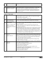
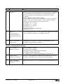
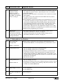
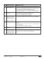
VITODENS 200
Troubleshooting Guide
This guide is for internal use only and is NOT a substitute for the technical support literature supplied with the Vitodens 200 boiler and the
accessories. Use in conjunction with Vitodens 200 Quick Start-up Guide and Start-up/Service Instructions.
Before getting started, remember…
•
All Vitodens 200 boilers have passed rigorous functionality testing and come factory-tested for proper
operation.
Approximately 85% of all field issues are associated with items external to the boiler, such as:
• Air in the water system (at start-up, air must be purged completely for at least 1 hour)
• Wrong programming (coding) match to connected system
• Air in the gas line (specifically for LP)
• Wrong pump designation, coding or assignment
• Power supply issues (reversed polarity, improper grounding, Ground Fault Interrupted supply, or
unstable power supply).
• Off-grid power supply such as generators, battery back-up.
•
Only a few measurements without burner calibrations need to be performed on the boiler. The following are
items that do require measurements:
• Inlet gas pressure (static and running)
• Combustion flue gases and air intake (for direct vent systems)
• Power supply
• Certain fuses
•
When changing the coding addresses the boiler must be restarted (power ON/OFF) at least once for the
changes to take effect. The control needs between 2 and 60 seconds to process and transfer data.
•
From our own experience, we have replaced the following components on the boilers in the following order:
• VR20 circuit board
• LGM burner control unit
• Fan assemblies
• Complete burner assembly (some due to damage of the inlet air damper)
•
When troubleshooting the Vitodens 200 avoid jumping to the premature conclusion that parts such as
VR20, LGM etc., or the boiler are defective. It is important to avoid this assumption.
Troubleshooting Steps When the Customer Calls
Step 1 Collect pertinent information. Please use the Vitodens Diagnostics sheets if possible. A copy is attached
at the end of this document for convenience.
Record the boiler model number, gas type, venting type, system layout connected to boiler, accessory and
equipment used (Low-Loss Header (LLH), mixing valves, etc).
5351 934 v1.0 10/2007
Page 1 of 16
Step 2 Follow start-up procedures
For new installations, the first tool is always the Quick Start-up Guide. There are Quick Start-up Guides for
each respective boiler size and version. Following all steps in the Quick Start-up Guide will resolve up to 90%
of the issues. Copies of all Quick Start-up Guides must be kept in the Vitodens 200 Service Binder.
For boilers that have already been in service for some time, see the following steps.
Step 3 Check the programming
Using the information collected in Step 1, go over the programming of the control unit using the updated
product manual. Pay special attention to the coding address “000:___”, “OB8:___”, “045:___”. Most problems
can be solved using the Installation, Start-up/Service and respective accessory manuals that are supplied with
the boiler.
Step 4 Refer to the service guide supplement
Use this Troubleshooting Guide to solve problems that could not be solved using the Quick Start-up Guide and
product service manuals. This Troubleshooting Guide contains the knowledge and experience of our Service
and Engineering Departments relating to unique and difficult-to-diagnose problems. This guide should help solve
95% of the remaining problems that cannot be solved with steps 1 – 3.
Step 5 Replace components
Once steps 1 – 4 are completed, it may still be necessary to replace a part (e.g. VR20 circuit board, LGM
burner control, etc.). Do not replace any parts prior to completing all previous steps. At this time the
Viessmann Service Departments located in Waterloo, Warwick or Langley need to be consulted.
Please avoid calling before having completed the previous steps.
Who to contact…
Viessmann Manufacturing
Company Inc.
Waterloo, ON
Tel. (519) 885-6300
Toll-Free (800) 387-7373
Viessmann Manufacturing.
Company (U.S.) Inc
Warwick, RI
Tel. (401) 732-0667
Toll-Free (800) 288-0667
Viessmann Manufacturing
Company Inc.
Langley, BC
Tel. (604) 533-9445
Toll-Free (877) 853-3288
5351 934 v1.0 10/2007
Page 2 of 16
Service Call Overview
Important: Read the information on pages 1 and 2 before using this guide. This guide assumes the reader is
familiar with the Vitodens product manuals and the Quick Start-up Guide (QSG).
When burner fault indicator (red LED) is lit, the boiler is in lockout mode and needs to be reset.
When a fault is flashing on the programming unit’s display, but the red light is not lit, the boiler need not be
reset and will resume operation as soon as the fault is acknowledged or corrected.
Item Field Service Calls
Suggested Solution
Section 1: Unusual boiler operation
1
Boiler does not start and
no fault code is
displayed on
programming unit’s
screen.
Model 6-24/8-32
2
Boiler does not start and
no fault code is
displayed on
programming unit’s
screen.
Model 11-44/15-60
Water pressure switch did not close (WB2-24C, -24, -32).
Check system pressure (must be above 12 psig).
Power on boiler and enter installer set-up. Go to Relay Test #10. If
boiler has stalled with no fault code displayed, remove wires from
pressure switch and jumper it. If boiler starts, replace the switch.
If boiler does not start, check for other probable causes, such as
incorrect voltage, defective VR20 board, LGM board etc.
Water flow switch did not close. Follow procedure as in item 1.
If boiler does not start, verify #20, #21 and #20A plugs for pump
connections in both PPM and orange boiler relay pump box.
If plug #20 was incorrectly used as system pump (#20A), change it
to #20A plug; boiler should then start (see QSG for pump diagrams).
If boiler does not start, check for other probable causes, such as
incorrect voltage, defective VR20 board, LGM board etc.
3
Boiler short cycling
Check for proper grounding of the boiler (dedicated ground, check
building ground).
Check for air in the system – purge until system is entirely free of air.
Check for proper water flow in the system (check for proper sizing of
pump(s) and pipes).
Low gas pressure while boiler is running. Check inlet gas valve
screen. Increase gas supply pressure if it is below the required
minimum.
Check for blocked air inlet on concentric venting system. (For testing
purposes only: remove burner cover to eliminate venting air intake
and to allow room air for combustion).
Flue gas leakages on concentric system (see flue gas test procedure
in Venting System Installation Instructions)
4
Boiler short cycling
When in DHW call for heat: ensure solenoid valve is installed straight
into the diverting valve against the seat, even if solenoid pulls in and
out normally as per Relay Test #04).
DHW coil resistance is high, especially with non-Viessmann tank.
Order PN 7134599.
Check for zone valves in the system. If present, they require a
separate pressure-activated bypass – Vitodens 200, WB2-24, -32
internal bypass is not designed to handle system flow. It is only used
for boiler pump protection. Use of Low Loss Header will help in this
situation.
Model 6-24/8-32
5351 934 v1.0 10/2007
Page 3 of 16
Field Service Calls
Suggested Solution
5
Boiler short cycling on a
short heating circuit
(ie: connected directly
to one mixing valve
heating circuit only “B”)
All model sizes
Set heating curves for heating circuit A, in this case the boiler, equal
to B (single circuit with mixing valve). Lower boiler factory default
differential setting from 8°C to 2°C to 3°C/ 4°F to 5°F (differential
temperature between A and B).
Use of Low Loss Header eliminates this problem.
6
Noise from boiler built-in
bypass valve
Systems with zone valves, controlled by other means such as room
thermostat, require separate pressure-activated bypass to be
installed.
See item 4.
Model 6-24/8-32
7
Fuse or circuit breaker
tripping
Check for hot/neutral polarity in the wall outlet.
Check if GFI is installed (see item 40).
For sizes 44/60 if 0.6 Amp fuse in PPM is blown replace with
equivalent 0.8 Amp fuse. (Viessmann PN 9066825)
8
Accessories (HK1,
…etc). BUS
Communication
Problems
Interference problem: Check proper connections using updated wiring
diagram. Note: Boiler relay test does not work with Viessmann 2-wire
BUS connection (additional mixing valves)
Check all proper coding / scan.
Use shielded/stranded wire.
9
Ice build-up on outside
vent termination
Usually associated with unusual boiler cycling.(see item 3,4)
Check outdoor sensor for proper reading.
Heating circuits A/B set points (see item 8).
Vent pipe slope (should slope back to boiler).
Replace VR20 board.
10
Unusual or erratic
operation of pumps, but
relay test shows normal
functioning
Verify all proper coding addresses and timer schedules.
Replace VR20 board.
Model 11-44/15-60; Change coding address 013:001 To 013:000 ;
pump runs during WWSD if left to 001 value
11
Gas odor outside
Check inlet gas pressure at highest input. Use relay test #11 or DHW
call for heat to put boiler at highest input and adjust as required.
Check inlet gas valve mesh screen for blockage, such as pipe debris
and flakes. If this happens frequently, contact Viessmann.
12
Boiler only operates
when “Party” mode
button is pressed
Pressing the “Party” mode button will activate the DHW recirculation
pump (#20 connection pump output). If heating pump #20A is
mistakenly connected into #20 in an installation without LLH, boiler
will fire only on “Party” mode. Note: If LLH is installed, there is no
DHW recirculation operation since pump #20 becomes boiler pump.
Model 11-44/15-60
5351 934 v1.0 10/2007
Page 4 of 16
Item Field Service Calls
Suggested Solution
13
Electrical Breakers
Tripping and GFCI's
Tripping
PPM Vitodens new Transformer Mar. 17/2004 SN:
6020264071162004
PM Vitodens new Transformer Apr. 16/2004 SN:
6020273649112004
Power/Pump modules produced before March 17, 2004 and Power
Modules produced before April 16, 2004 have an 'autotransformer'
style of transformer. These may cause breakers and/or GFCI's to trip
if the Line/Neutral are reversed.
Power/Pump modules produced after March 17, 2004 and Power
Modules produced after April 16, 2004 have isolation transformer.
These do not cause breakers and/or GFCI's to trip with Line/Neutral
reversal.
FYI: How to read serial number: First six numbers are product part
number, last six numbers are week and year code. Digits in the
middle are sequential numbers
14
Boiler will not fire on
relay test #10 & #11
This occurs when Vitodens boiler is connected to one single circuit
with mixing valve. To protect the heating circuit during all relay tests,
mixing valve closes completely. As a result there will be no flow
through the boiler. In this case, another way should be determined to
get flow. Protect any RFH circuit from excessive water temperatures
during relay test.
Model 11-44/15-60
15
Noisy boiler operation /
Coaxial vent damaged in
shipping/transport.
Improper packaging and handling.
May need packaging reinforcement to protect the vent pipe.
Ensure that coaxial vent pipe adaptor is not deformed. This may
cause air noise or whistling due to the reduced air gap.
16
Maximum boiler
temperature 75°C/
167°F (does not go up
to 82°C/ 180°F at
design)
Boiler starts modulating down as boiler temperature approaches
75°C/167°F (modulating boiler). Between 75°C/167F to 82°C/180F
boiler operates (on min. fire) until load is satisfied – shut down at
maximum adjustable setting (82°C/180°F) under coding address 042.
17
Erratic operation of
heating and DHW
Verify correct time and date settings of programming unit. Incorrectly
programmed time clock or timer schedules can cause erratic boiler
operation.
Verify timer schedules when DHW is produced and DHW recirc pump
operation.
Sun and moon dial determines day- and night-time space heating
room temperatures.
18
Boiler power switch not
functional
When mounting Programming Assembly onto the boiler ensure the
power switch is properly inserted into the rear opening provided on
base of programming unit. Ensure switch (c/w spring) is moving
freely.
5351 934 v1.0 10/2007
Page 5 of 16
Troubleshooting Fault Code 06
5351 934 v1.0 10/2007
Page 6 of 16
Field Service Calls
19
Problems with multiple
Vitodens installations
Suggested Solution
For custom projects, i.e. boilers with Vitocontrol-C, contact KW
Electronic Service. For problems with Vitocontrol-S, refer to
respective manuals and Quick Start-up Guide developed by KWE.
Also refer to the issue of “Vitotalk”, addressing the operation of
Cascade Controls.
Section 2: Fault codes
20
Fault A1
Acknowledge fault and reset.
Power boiler on and off, remove VR20 circuit board and reinstall.
Power boiler on and off again.
If fault code A1 reappears, replace LGM.
21
Fault A4 (Also see
Service Instructions)
Verify coding address 0B8:006 and change value accordingly.
22
B1 fault code
Low battery charge or dip switch setting of programming unit (rear)
are not set properly.
Replace batteries or check dip switches and clear fault code.
If fault code reappears, turn boiler off, remove VR20 circuit board,
and power the boiler on.
Reinstall VR20 circuit board ensuring that it makes positive contacts.
If boiler starts (after a few seconds), but no temperature display is
present, replace VR20 board and entire programming unit. Usually
boiler operates in the background without proper communication with
programming unit. For example, DHW production activates on a call
for domestic hot water and boiler starts firing.
(leads to no Boiler temp
display/no access to
system menu or installer
set up)
23
Fault F4
Model 6-24/8-32
24
Fault 06
Fault 07
5351 934 v1.0 10/2007
Air in the system leads to pump racing. Observe boiler temperature;
high temperature spikes may lead to fault 02 (fixed high limit switch);
Bleed air from both systems (domestic hot water and space heating).
Use yellow cap provided with the DHW solenoid valve. Bleed the
pump itself using the screw pump head.
Disconnect pump communication plug #145 and change coding
address 013:001 to 013:000.
If boiler is connected to OFF-grid power supply, contact Viessmann.
Air supply to boiler is insufficient.
Check for ice blockage on vent termination.
Check maximum flue pipe length.
Severe local wind conditions.
Check location of side wall terminal (see compliance to all
requirements stated in venting manual).
Defective or blown fuse on orange electronic fan control box (for
44/60 only). Replace entire box.
Defective pressure transducer.
Page 7 of 16
Item Field Service Calls
Suggested Solution
25
Fault 14
Gas line needs to be purged extensively on new propane installations
or when boiler was not in operation for extended period of time.
Verify gas regulator and working inlet gas pressure (not static
pressure).
Check ionization current. Check for gaps.
Input voltage to ionization rod must be approx. 160 to 170 VAC (to
ground). If it is not, check polarity (L, N, G) of the power supply.
Check resistance of gas valve coils with power off.
Terminals 1,2→~ 51.7Ω
Terminals 1,3→~ 51.7Ω
Terminals 2,3→~103.5Ω
Check orifice size.
Check spark and ignition transformer.
See also item #11.
26
Fault 14
With two boilers
installed, sometimes
only one goes into lockout
Verify gas pressure inlet with both boilers running high. Run relay test
#11, if needed to simulate, or run DHW for high fire.
27
Outdoor Temperature
Sensor Fault
If resistance is within limits, wiring is correct and sensor is not
defective, replace VR20 circuit board.
Section 3: Unusual screen displays
28
“EXT. program 2,”
appears on screen
Usually appears at start-up.
Verify all coding addresses.
If problem persists, replace VR20 circuit board.
If problem persists, replace LGM.
If problem persists, replace programming unit control console.
29
“Boiler enabling”
appears on the display
Verify all coding addresses, especially those designated for “Do not
change”). These must stay in their factory default settings.
30
Boiler temperature
display unit displays
only in °C
Cannot be changed to °F when remotely mounting programming unit.
5351 934 v1.0 10/2007
Page 8 of 16
Item Field Service Calls
Suggested Solution
31
Dashes displayed
instead of coding
values, e.g. 000- - -.
System address 000:
and OB8: not displayed
when in coding 2.
Check all external wiring, and that accessories to the boiler, such as
LLH, DHW and outdoor sensor, specifically X6.1/6.2, are installed
and wired properly.
Ensure no room thermostat is connected to X6.1 and X6.2 (common
field mistake).
Turn boiler on/off a few times and ensure VR20 board is properly
installed with good contacts.
Electromagnetic interference problem with programming unit, such as
in industrial installations and gas heating stations, can be solved by
removing the programming unit and using remote wall-mount base
(room dependent operation) wired into X6.1 and X6.2. Also, install
temperature display unit on boiler (for boiler code requirements).
Ensure that S1 DIP switch at rear temperature display is set to OFF.
Verify proper installation of programming unit console onto the boiler.
Replace entire programming unit console.
32
Extreme low
temperature conditions
may cause ice buildup
on side wall and vertical
venting termination
Side wall venting screen can be field modified. Please call for
information (see Who to contact…on page 2).
Vertical venting screen can be field modified. Please call for
information (see Who to contact…on page 2).
Section 4: Coding address modifications
33
Not enough flow
through boiler
Boiler pump is undersized. Use Grundfos pumps specified in the
Technical Data Manual, or their equivalent, e.g. TACO 0011, 0014.
Model 11-44/15-60
34
Coding address 015
“Do not change” 015:000 for 6-24C/6-24/8-32.
“Do not change” 015:001 for 11-44/15-60.
Changing this address from 015:000 to 015:001 on models 6-24C,
6-24, 8-32 will result in boiler firing without circulation pump and
solenoid valve energized on a DHW call for heat. For models 11-44
to15-60 changing the address from 015:001 to 015:000 will result in
DHW pump not energized.
May lead to fault 02.
35
Coding address 017
“Do not change” 017:001.
Changing this address from factory default setting will result in burner
firing without circulation pump operating. May lead to fault 02. Has
no effect on models WB2-44/60
Model 6-24/8-32
36
OD6 coding (°C to °F)
°C for addresses.
°F for display only.
37
Not able to change the
date
See coding OC7.
5351 934 v1.0 10/2007
Page 9 of 16
Item Field Service Calls
38
Snow melt and pool
heating
Suggested Solution
Requires installation of a secondary heat exchanger, (Glycol 50%,
max.)
Do not use Vitodens in open loop pool heating system.
Section 5: Frequently asked questions
39
Do I need a drain fitting
for the venting system?
You do not need a drain fitting and you do not need a different rain
cap. Boiler will be able to handle the condensation in the vent.
40
Can I use stainless steel
Flex pipe to vent?
The Vitodens cannot be vented with a flex pipe, even though flex
pipe is made of a UL listed AL-29-4C corrosion resistant material.
These liners are only approved for category I appliances (for lining a
masonry chimney). They are not approved for category IV boilers like
the Vitodens. If you find a flex liner in the North American market
that is approved for category IV, please send us the information to
review.
41
Gap seems too large
around single wall vent
pipe adaptor
Use a high-temperature silicon compound to fill in the gap.
42
How do OB8 coding and
anti-legionnaire function
operate?
The OB8:001 means DHW (without anti-legionnaire function);
The OB8:002 means DHW (with anti-legionnaire function);
Once the DHW sensor is plugged in, address 000:… and OB8 must
be verified and set manually, if required.
anti-legionnaire function:
If there is no call for DHW in a period of 24 hours, the anti-legionnaire
function is initiated by the control and heats up the tank to 140° F /
60° C for a period of 10 minutes. This 10-minute period must lie
outside the programmed DHW switching times for the anti-legionnaire
function so that the control can sense it. See also coding address
OA7 for factory default setting (OA7:060) and possible changes
(OA7:061 to 070). We prefer to leave it at Factory Default setting,
due to the maximum boiler limitations (172.4 °F/78 °C) for DHW. If
coding address OA7 is set to 070, the boiler may need more time to
reach this temperature and therefore might not respond quickly to a
call for heat and be blocked in DHW (especially models WB2-24C,
-24, -32). Do not set DHW temperature controller higher than 140 °F
/ 60 °C. This is applicable to all Vitodens boilers.
5351 934 v1.0 10/2007
Page 10 of 16
Item Field Service Calls
Suggested Solution
43
Replacement parts
Complete burner assembly comes with NG orifice installed in the gas
valve. Each burner assembly is shipped with LP conversion kit and
comes with Service Instructions and Warning Labels.
Gas valves are shipped with warning labels and instructions, but
without orifice installed. Use the orifice from the existing gas valve.
44
Fault A3
Bus communication problem with Cascade Control.
Check wire to X5 plug for proper connection.
Boiler control or Cascade Control is defective.
45
Replacement ionization
electrodes are not the
same size and shape
There are three different designs of electrodes. All are compatible.
Model 11-44/15-60
46
Fault F3
Check connections/wiring to low-loss header sensor of Cascade
Control
Check accessories, e.g. outdoor temp. sensor, low-loss header sensor
of Cascade control
Check Cascade Control. Replace if necessary.
47
Fault CC
Reset boiler. If red light reappears and boiler goes into lockout mode,
replace LGM 29.XX.
48
Boiler does not ramp up
to high fire (specially in
multiple boiler systems
with cascade control).
Check inlet gas valve mesh screen for blockage. Clean it. If the issue
reports more than 2 times a year contact Viessmann.
5351 934 v1.0 10/2007
Page 11 of 16
VITODENS 200
Diagnostic Sheets
CAUTION
WARNING
The installation, adjustment, service,
and maintenance of this product must
be done by a licensed professional
heating contractor who is qualified
and experienced in the installation,
service and maintenance of hot water
boilers. There are no user serviceable
parts on the boiler, burner, or control.
Ensure main power supply to
equipment, the heating system, and
all external controls have been
deactivated. Close main gas supply
valve. Take precautions in all
instances to avoid accidental
activation of power during service
work.
Please include all of the information requested to facilitate the diagnosis and fax it back to
_______________________________________________ at
_______________________________
Mechanical Contractor: _____________________________________________________________________________________________
Address:
_____________________________________________________________________________________________
_____________________________________________________________________________________________
Tel:
_____________________________________________________________________________________________
Contact Person:
_____________________________________________________________________________________________
Date Installed:
_____________________________________________________________________________________________
Project Name:
_____________________________________________________________________________________________
Project Address:
_____________________________________________________________________________________________
_____________________________________________________________________________________________
Tel:
_____________________________________________________________________________________________
Contact Person:
_____________________________________________________________________________________________
Altitude of Installation: ________________________________________ feet
Residence / Home
Installation in:
Commercial / Industrial
Heating Boiler
Model:
WB2-
ASME Serial No.:
_____________________________________________________________________________________________
Fuel Supply:
DHW Model (if applicable):
NG
6-24C
6-24
8-32
11-44
15-60
LP
Brand: ________________________________
Size: ___________________________________
Boiler Installation Checklist
The following information must be made available to us to assist in the diagnosis.
System Layout
Using the booklets supplied with the boiler provide the following information:
1.
Date on cover of Installation Instructions: month ____________ year ____________
2.
The page number of the Installation Instructions for the system type: Page No. ____________
Installation and Activation Requirements. Please Provide:
Heat loss calculations
Flow calculations (GPM at ft head for each pump in system)
DHW Tank coil flow rate and head ____________ ____________
Venting material: ______________________________________________ (include sketch)
Gas pressure measured at full fire _____________________
Gas valve screws x, y readjusted?
Yes
No
Boiler water pressure ____________ temperature ____________
Electrical polarity and grounding at #40 plug confirmed. L & N terminal ____________
Power source:
grid
generator
External gas filter installed
Yes
inverter
No
If LLH installed, is Viessmann #5 sensor connected to boiler?
Single boiler installation
with Cascade control
Yes
No
No LLH
without Cascade control
Boiler / System Parameters Checklist. Please ensure that you have reviewed the items below:
Wiring in Power Pump Module correct (quick set-up)
Max temperature set A / B
Wiring in Vitodens correct (schematic)
Differential set-point
Coding addresses match system
DHW set-point / optimum switch position
Relay test as per manual
Burner micro-amp signal measured
Sensor test as per manual
Saved fault code retrieval
Operating status information O.K.
Vitodens control batteries, remote mount
Mixing valve direction, dip switches
Remote enable / disable function
Time and date set correctly
LLH sensor actual temperature reading
All timer schedules
Btu/h matches load
Heating curves A / B
Integration with other heat sources
Shift A / B
Vitodens control DIP switch (S1 & S2) at the back
System Sketch
If the diagram as provided in the Installation Instructions was not followed, the following information is required. Include
this information on the separate sheet attached. If floor heat design software can assist in answering the following
questions, please include it in your response.
Piping schematic including boiler feed
Circuit water temperature requirements
Piping diameters and lengths
Circuit Btu requirements
Individual circuit flow, GPM required
Total Btu load
Foot of head for each circuit
Circulator sizes (model numbers)
Calculated Delta T for each circuit
Address
Recorded Value
Address
000
015
003
017
005
108
007
019
008
020
010
027
011
028
013
038
Address
Recorded Value
Address
042
0B2
044
0B3
045
0B8
046
0C1
099
0C5
0A0
0D7
0A2
Scan 1
0A7
Scan 2
0A9
Recorded Value
Recorded Value
System Sketch
Printed on environmentally friendly
(recycled and recyclable) paper.
Viessmann Sales Center
Langley, BC Canada
Tel. (604) 533-9445
Fax. (604) 533-9439
Technical information subject to change without notice
Viessmann Manufacturing
Company (U.S.) Inc.
Warwick, RI USA
Tel. (401) 732-0667
Fax (401) 732-0590
5351 934 v1.5
Viessmann Manufacturing
Company Inc.
Waterloo, ON Canada
Tel. (519) 885-6300
Fax (519) 885-0887