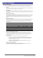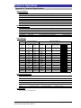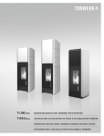
1
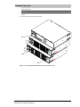
Rack-Mount Fail-Safe Transfer Switch Installation and Operations Manual C-8HFx C-16HFx © 2006-2011 Server Technology, Inc. All rights reserved. Instructions This symbol is intended to alert the user to the presence of important operating and maintenance (servicing) instructions in the literature accompanying the appliance. Dangerous Voltage This symbol is intended to alert the user to the presence of un-insulated dangerous voltage within the product’s enclosure that may be of sufficient magnitude to constitute a risk of electric shock to persons. Protective Grounding Terminal This symbol indicates a terminal that must be connected to earth ground prior to making any other connections to the equipment. Life-Support Policy As a general policy, Server Technology does not recommend the use of any of its products in the following situations: life-support applications where failure or malfunction of the Server Technology product can be reasonably expected to cause failure of the life-support device or to significantly affect its safety or effectiveness. direct patient care. Server Technology will not knowingly sell its products for use in such applications unless it receives in writing assurances satisfactory to Server Technology that: the risks of injury or damage have been minimized, the customer assumes all such risks, and the liability of Server Technology is adequately protected under the circumstances. The term life-support device includes but is not limited to neonatal oxygen analyzers, nerve stimulators (whether used for anesthesia, pain relief or other purposes), auto-transfusion devices, blood pumps, defibrillators, arrhythmia detectors and alarms, pacemakers, hemodialysis systems, peritoneal dialysis systems, neonatal ventilator incubators, ventilators (for adults or infants), anesthesia ventilators, infusion pumps, and any other devices designated as “critical” by the U.S. FDA. Notices 301-0128-1 Rev. D (011711) Copyright © 2006-2011 Server Technology, Inc. All rights reserved. 1040 Sandhill Drive Reno, Nevada 89521 USA All Rights Reserved This publication is protected by copyright and all rights are reserved. No part of it may be reproduced or transmitted by any means or in any form, without prior consent in writing from Server Technology. The information in this document has been carefully checked and is believed to be accurate. However, changes are made periodically. These changes are incorporated in newer publication editions. Server Technology may improve and/or change products described in this publication at any time. Due to continuing system improvements, Server Technology is not responsible for inaccurate information which may appear in this manual. For the latest product updates, consult the Server Technology web site at www.servertech.com. In no event will Server Technology be liable for direct, indirect, special, exemplary, incidental or consequential damages resulting from any defect or omission in this document, even if advised of the possibility of such damages. In the interest of continued product development, Server Technology reserves the right to make improvements in this document and the products it describes at any time, without notices or obligation. Other trademarks and trade names may be used in this document to refer to either the entities claiming the marks and names or their products. Server Technology, Inc. disclaims any proprietary interest in trademarks and trade names other than its own. The Globe logo is a trademark of Server Technology, Inc., registered in the US. Use of the logo for commercial purposes without the prior written consent of Server Technology may constitute trademark infringement and unfair competition in violation of federal and state laws. Server Technology and the Globe logo are trademarks of Server Technology, Inc., registered in the US. Sentry, Cabinet Distribution Unit, Rack-Mount Fail-Safe Transfer Switch, and SMARTER Technical Support are trademarks of Server Technology, Inc. Please Recycle Shipping materials are recyclable. Please save them for later use, or dispose of them appropriately. Table of Contents CHAPTER 1: INTRODUCTION 4 Quick Start Guide.............................................................................................................................4 Technical Support ............................................................................................................................4 Equipment Overview........................................................................................................................5 CHAPTER 2: INSTALLATION 6 Standard Accessories........................................................................................................................6 Additional Required Items ...............................................................................................................6 Safety Precautions ............................................................................................................................6 Installing the Power Input Retention Bracket...................................................................................7 Mounting ..........................................................................................................................................7 Optimizing the Transfer Thresholds.................................................................................................7 Connecting to the Power Source ......................................................................................................7 Connecting Devices..........................................................................................................................7 CHAPTER 3: OPERATIONS 8 Modes of Operation..........................................................................................................................8 CHAPTER 4: APPENDICES Appendix A: Technical Specifications .............................................................................................9 Appendix B: Warranty, Product Registration and Support ............................................................11 9 Chapter 1: Introduction Quick Start Guide The following instructions will help you quickly install and configure your Rack-Mount Fail-Safe Transfer Switch for use on your network. For detailed information on each step, go to the page number listed to the right. 1. 2. 3. 4. Mount the Rack-Mount Fail-Safe Transfer Switch ....................................................................7 Optimize the transfer thresholds.................................................................................................7 Connect to the power sources.....................................................................................................7 Connect the devices to the Fail-Safe Transfer Switch................................................................7 Technical Support Experience Server Technology's FREE SMARTER Technical Support - Learn more... Server Technology understands that there are often questions when installing and/or using a new product. Free Technical Support is provided from 6:00 AM to 7:00 PM, Monday-Friday, Pacific Time. Server Technology, Inc. 1040 Sandhill Drive Reno, Nevada 89521 USA 4 Introduction Tel: 775.284.2000 Fax: 775.284.2065 Web: www.servertech.com Email: [email protected] Rack-Mount Fail-safe Transfer Switch Installation and Operations Manual Equipment Overview 1. The Voltage Selector switch configures the Rack-Mount Fail-Safe Transfer Switch for the installed operational voltage. NOTE: This configures the brownout/over-voltage switching points. 2. 3. The power inlets connect the Rack-Mount Fail-Safe Transfer Switch to the electrical power sources. LEDs display the input feeds power status. 1 2 3 Figure 1. Sentry Rack-Mount Fail-Safe Transfer Switch Views Rack-Mount Fail-safe Transfer Switch Installation and Operations Manual Introduction 5 Chapter 2: Installation Before installing your Rack-Mount Fail-Safe Transfer Switch, refer to the following lists to ensure that you have all the items shipped with the unit as well as all other items required for proper installation. Standard Accessories Mounting hardware: Two removable flanges with M4 screws. Outlet retention clips (208-240V models). Additional items for Cx-xxx-C20 models: Separate power input cords. Power input retention bracket hardware (may be installed): Four removable T-brackets with four 40mm screws. Additional Required Items Flathead and Phillips screwdrivers Screws, washers and nuts to attach the CDU to your rack Safety Precautions This section contains important safety and regulatory information that should be reviewed before installing and using the Sentry Rack-Mount Fail-Safe Transfer Switch. For input and output current ratings, see Power Ratings in Appendix A: Technical Specifications. Only for installation and use in a Service Access Location in accordance with the following installation and use instructions. This equipment is designed to be installed on a dedicated circuit. Dedicated circuit must have circuit breaker or fuse protection. CDUs have been designed without a master circuit breaker or fuse to avoid becoming a single point of failure. It is the customer’s responsibility to provide adequate protection for the dedicated power circuit. Protection of capacity equal to the current rating of the CDU must be provided and must meet all applicable codes and regulations. In North American, protection must have a 10,000A interrupt capacity. Destiné à l'installation et l'utilisation dans le cadre de Service Access Location selon les instructions d'installation et d'utilisation. Cet équipement est conçu à être installé sur un circuit spécialisé. Le circuit spécialisé doit avoir un disjoncteur ou une protection de fusible. CDUs ont été conçus sans disjoncteur général ni fusible pour éviter que cela devient un seul endroit de panne. C’est la responsabilité du client de fournir une protection adéquate pour le circuit-alimentation spécialisé. Protection de capacité équivalant à la puissance de l'équipement, et respectant tous les codes et normes applicables. Les disjoncteurs ou fusibles destinés à l'installation en Amérique du Nord doivent avoir une capacité d'interruption de 10.000 A. The plug on the power supply cord shall be installed near the equipment and shall be easily accessible. Always disconnect the power supply cords before opening to avoid electrical shock. WARNING! High leakage current! Earth connection is essential before connecting supply! La prise sur le cordon d’alimentation sera installée près de l’équipement et sera facilement disponible. Nur für Installation und Gebrauch an Anschlusszugriffspunkten gemäß der folgenden Installations- und Gebrauchsanweisungen. Diese Ausrüstung ist zur Installation in einem festen Stromkreis vorgesehen. Der feste Stromkreis muss mit einem Schutzschalter oder einem Sicherungsschutz versehen sein. CDUs verfügt über keinen Hauptschutzschalter bzw. über keine Sicherung, damit kein einzelner Fehlerpunkt entstehen kann. Der Kunde ist dafür verantwortlich, den Stromkreis sachgemäß zu schützen. Der Kapazitätsschutz entspricht der aktuellen Stromstärke der Geräte und muss alle relevanten Codes und Bestimmungen erfüllen. Für Installation in Nordamerika müssen Ausschalter bzw. Sicherung über 10.000 A Unterbrechungskapazität verfügen. Der Stecker des Netzkabels muss in der Nähe der Ausrüstung installiert werden und leicht zugänglich sein. Toujours déconnecter le cordon d’alimentation avant d’ouvrir pour éviter un choque électrique. ATTENTION ! Haut fuite très possible ! Une connection de masse est essentielle avant de connecter l’alimentation ! ATTENTION! Les unités Cx-xxE-x Double Pôle/Fusible sur le Neutre Ziehen Sie vor dem Öffnen immer das Netzkabel heraus, um die Gefahr eines elektrischen Schlags zu vermeiden. ACHTUNG! Hoher Ableitstrom! Ein Erdungsanschluss ist vor dem Einschalten der Stromzufuhr erforderlich! ACHTUNG!: Cx-xxE-x Zweipolige bzw. Neutralleiter-Sicherung WARNING! Cx-xxE-x units Double Pole/Neutral Fusing 6 Installation Rack-Mount Fail-safe Transfer Switch Installation and Operations Manual Installing the Power Input Retention Bracket For units with a total maximum output <30A, it may be necessary to install the power input retention bracket prior to mounting the unit within the rack. To install the power input retention bracket: 1. 2. Remove the two screws attaching the IEC 60320 C19 inlet to the enclosure. Assemble and attach the retention bracket to the enclosure as shown. Figure 2.1 Retention Bracket assembly Mounting 1. 2. 3. Select the appropriate bracket mounting points for proper mounting depth within the rack. Attach the brackets to these mounting points with two screws for each bracket. Install the enclosure into your rack, using the slots in each bracket. The slots allow about ¼ inch of horizontal adaptability to align with the mounting holes of your rack. NOTE: A mounting bracket kit for 23” wide racks or cabinets is available. Contact your Server Technology Sales Representative for more information. Figure 2. Mounting Optimizing the Transfer Thresholds The Voltage Selector switch is used to optimize the transfer threshold by configuring the Transfer Switch for the nominal operational voltage of the installation. The Transfer Switch uses this setting to calculate the brownout and over-voltage threshold (± 13% ). To optimize the transfer threshold: Select the voltage setting that most closely matches the nominal operating voltage of the power sources. Connecting to the Power Source To attach a power cord to the unit: 1. 2. Plug the female end of the power cord firmly into its connector at the base. Use a screwdriver to tighten the two screws on the retention bracket. To connect to the power source: Plug the male end of the power cord into the AC power source. Connecting Devices 1. 2. Keep the device’s on/off switch in the off position until after it is plugged into the outlet. Connect devices to the CDU outlets. NOTE: Server Technology recommends even distribution of attached devices across all available outlets to avoid exceeding the outlet, branch or phase limitations. See Power Ratings on page 9 for more information. Always disconnect ALL power supply cords before opening to avoid electrical shock. Afin d’éviter les chocs électriques, débranchez TOUTES les cables électrique avant d’ouvrir. Immer ALLE Netzleitungen auskuppeln vor den Aufmachen um elektrischen Schlag zu vermeiden. Rack-Mount Fail-safe Transfer Switch Installation and Operations Manual Installation 7 Chapter 3: Operations Modes of Operation The Sentry Rack-Mount Fail-Safe Transfer Switch is designed to operate in the following modes: Normal Infeed A provides power to branches A1 & A2 and Infeed B provides power to branches B1 & B2. Each infeed is monitored individually for voltage and current. Input Failure The equipment powered by the failed input is transferred to the remaining input. The input current LED display of the failed input will be blank and the remaining display will report the total current load for the unit. Recovery from Input Failure When voltage is restored to the failed input and remains within ±7% of nominal for 2 seconds, the equipment normally supported by that input is transferred back returning the Sentry to a ‘Normal’ mode with the input current LED displays reporting the total current load for each respective infeed. Brownout/Over-Voltage When an input’s voltage varies from its nominal by ±13% or more, the equipment powered by that input is transferred to the remaining input. The input current LED display of the input in the brownout/over-voltage state will be blank and the remaining display will report the total current load for the unit. Nominal Voltage* 100V 110V 115V 120V 208V 220V 230V 240V * Brownout 87.0V 95.7V 100.0V 104.4V 181.0V 191.4V 200.1V 208.8V Recovery Voltage 93.0V 102.3V 106.9V 111.6V 193.4V 204.6V 213.9V 223.2V Over-Voltage 107.0V 117.7V 123.0V 128.4V 222.6V 235.4V 246.1V 256.8V 113.0V 124.3V 129.9V 135.6V 235.0V 248.6V 259.9V 271.2V Nominal operating voltage is configured by the Voltage Selector Switch. Recovery from Brownout/Over-Voltage When the input’s voltage returns to and remains within ±7% of nominal for 2 seconds, the equipment normally supported by that input is transferred back returning the Sentry to a ‘Normal’ mode input current LED displays reporting the total current load for each respective infeed. Critical Brownout A critical brownout is when an input’s voltage drops below its nominal by -25%. 8 When an input is already in a brownout/over-voltage state AND the remaining input experiences a critical brownout, ALL equipment will be transferred to the input only experiencing a brownout/over-voltage. When an input has already failed AND the remaining input experiences a critical brownout, ALL outlets will turn off. Recovery from Critical Brownout When the input’s voltage returns to and remains within ±7% of nominal for 2 seconds, the equipment normally supported by that input is transferred back. Operations Rack-Mount Fail-safe Transfer Switch Installation and Operations Manual Chapter 4: Appendices Appendix A: Technical Specifications Domestic Models Model Rated Voltage Input Cordset and Plug (10’) C-8HF2-C203 C-8HF2-L303 C-16HF1-C20 C-16HF1-L30 C-16HF2-C20 C-16HF2-L30 208-240V, 60Hz 208-240V, 60Hz 100-120V, 60Hz 100-120V, 60Hz 208-240V, 60Hz 208-240V, 60Hz IEC 60320 C20 2 x NEMA L6-30P, 30A/208V Locking 1 IEC 60320 C20 2 x NEMA L5-30P, 30A/120V Locking 1 IEC 60320 C20 2 x NEMA L6-30P, 30A/208V Locking Outlets 1 8 IEC 60320/C19 8 IEC 60320/C19 16 NEMA 5-20R 16 NEMA 5-20R 16 IEC 60320/C13 16 IEC 60320/C13 International Models Model Rated Voltage C-8HFE-C203 C-8HFE-P323 C-16HFE-C20 C-16HFE-P32 1 Input Cordset and Plug (10’) Outlets 1 230V, 50Hz 230V, 50Hz 230V, 50Hz 230V, 50Hz IEC 60320 C20 2 x IEC 60309, 32A 3-pin 6Hr Blue 1 IEC 60320 C20 2 x IEC 60309, 32A 3-pin 6Hr Blue 8 IEC 60320/C19 8 IEC 60320/C19 16 IEC 60320/C13 16 IEC 60320/C13 Input cordset selected at time of purchase Power Ratings Input Current Ratings1 Output Current Ratings L’indice du courant d’entrée Eingangsstromstärke L’indice du courant de sortie Ausgangsstromstärke Model Voltage Current Voltage Outlet Branch Circuit M odele Tension Courrant Tension Prise Circuit de la Branche Phase Total T otal Modell Spannung Strom Spannung Anschlussstelle Zweigstromkreis Insgesamt A: 16 100-120V 100-120V 16 16 16 B: 16 60Hz 60Hz 100-120V A: 24 100-120V C-16HF1-L30 16 16 24 60Hz B: 24 60Hz A: 16 208-240V 208-240V C-8HF2-C203 16 16 16 B: 16 60Hz 60Hz A: 24 208-240V 208-240V 16 16 24 C-8HF2-L303 B: 24 60Hz 60Hz 208-240V A: 16 208-240V C-16HF2-C20 12 16 16 60Hz B: 16 60Hz 208-240V A: 24 208-240V C-16HF2-L30 12 16 24 60Hz B: 24 60Hz 230V A: 16 230V C-8HFE-C203 16 16 16 50Hz B: 16 50Hz 230V A: 32 230V C-8HFE-P323 16 20 32 50Hz B: 32 50Hz 230V A: 16 230V C-16HFE-C20 10 16 16 50Hz B: 16 50Hz 230V A: 32 230V C-16HFE-P32 10 20 32 50Hz B: 32 50Hz 1 All current ratings are in amperes. Tous les indices de courant sont en ampères. Alle Angaben der Stromstärke erfolgen in Ampere. C-16HF1-C20 Physical Specifications Operating Storage Temperature 32° to 104° F (0° to 40° C) -40° to 185° F (-40° to 85° C) Elevation(above MSL) 0 to 10,000 ft (0 to 3000m) 0 to 50,000 ft (0 to 15000m) Relative Humidity 10 to 90%, non-condensing 10 to 90%, non-condensing C-xHF 3.5 x 17.0 x 14.0 in. Dimensions (H x W x D) Weight (90 x 437 x 356 mm) 20.7 lbs (9.4 kg) Transfer Rate Power transfer ≤ 18 milliseconds. Rack-Mount Fail-safe Transfer Switch Installation and Operations Manual Appendices 9 Regulatory Compliance Product Safety Units have been safety tested and certified to the following standards: USA/Canada European Union UL 60950:2003 and CAN/CSA 22.2 No. 60950-1-03 EN60950-1:2001 This product is also designed for Norwegian IT power system with phase-to phase voltage 230V. USA Notification Note: This equipment has been tested and found to comply with the limits for a Class A digital device, pursuant to part 15 of the FCC Rules. These limits are designed to provide reasonable protection against harmful interference when the equipment is operated in a commercial environment. This equipment generates, uses, and can radiate radio frequency energy and, if not installed and used in accordance with the instruction manual, may cause harmful interference to radio communications. Operation of this equipment in a residential area is likely to cause harmful interference in which case the user will be required to correct the interference at the user’s own expense. Modifications not expressly approved by the manufacturer could void the user's authority to operated the equipment under FCC rules. Canadian Notification This Class A digital apparatus complies meets all requirements of the Canadian Interference-Causing Equipment Regulations. Cet appareil numérique de la classe A respecte toutes les exigencies du Règlement sur le matériel brouilleur du Canada. European Union Notification Products with the CE Marking comply with both the EMC Directive (89/336/EEC) and the Low Voltage Directive (73/23/EEC) issued by the Commission of the European Community. Compliance with these directives implies conformity to the following European Norms: EN55022 EN55024 EN60950-1 EN61000-3 Electromagnetic Interference Electromagnetic Immunity Product Safety Harmonics and Flicker Products with the following mark comply with the RoHS Directive (2002/95/EC) issued by the Commission of the European Community. Japanese Notification この装置は、情報処理装置等電波障害自主規制協議会(VCCI)の基準に基づくクラ スA情報技術装置です。この装置を家庭環境で使用すると電波妨害を引き起こすことが あります。この場合には使用者が適切な対策を講ずるよう要求されることがあります。 Recycling Server Technology Inc. encourages the recycling of its products. Disposal facilities, environmental conditions and regulations vary across local, state and country jurisdictions, so Server Technology encourages consultation with qualified professional and applicable regulations and authorities within your region to ensure proper disposal. Waste Electrical and Electronic Equipment (WEEE) In the European Union, this label indicates that this product should not be disposed of with household waste. It should be deposited at an appropriate facility to enable recovery and recycling. For information on how to recycle this product responsibly in your country, please visit: www.servertech.com/support/recycling. 10 Appendices Rack-Mount Fail-safe Transfer Switch Installation and Operations Manual Appendix B: Warranty, Product Registration and Support Warranty For Server Technology Warranty information, please see our website. Product Registration Registration is your key to special offers and services reserved for Registered Users. Excellent Technical Support Services Special Update and Upgrade Programs Warranty Protection Extended Warranty Service New Product Information Register your products online today! Technical Support Experience Server Technology's FREE SMARTER Technical Support - Learn more... Server Technology understands that there are often questions when installing and/or using a new product. Free Technical Support is provided from 6:00 AM to 7:00 PM, Monday-Friday, Pacific Time. Server Technology, Inc. 1040 Sandhill Drive Reno, Nevada 89521 USA Tel: 775.284.2000 Fax: 775.284.2065 Web: www.servertech.com Email: [email protected] Return Merchandise Authorization If you have a unit that is not functioning properly and is in need of technical assistance or repair: Please review Server Technology’s Return Merchandise Authorization process on our website. Rack-Mount Fail-safe Transfer Switch Installation and Operations Manual Appendices 11 Server Technology HEADQUARTERS – NORTH AMERICA EMEA APAC Server Technology, Inc. 1040 Sandhill Drive Reno, NV 89521 United States +1.775.284.2000 Tel +1.775.284.2065 Fax [email protected] www.servertech.com www.servertechblog.com Server Technology Intl Sienna Court The Broadway Maidenhead Berkshire SL6 1NJ United Kingdom +44 (0) 1628 509503 Tel +44 (0) 1628 509100 Fax [email protected] Server Technology, Inc. Singapore +65 (0) 6829 7008 Tel +65 (0) 6234 4574 Fax [email protected]