1
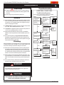
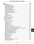
fire feature www.montigo.com Installation Operation & Maintenance Manual Check local codes and read all instructions prior to installation. C-View Residential Fireplace BF-Series SS Gas Fireplace R520 Indoor R620 Indoor Warning: If the information in these instructions is not followed exactly, a fire or explosion may result causing property damage, personal injury or death. Warning: WHAT TO DO IF YOU SMELL GAS Improper installation, adjustment, alteration, service or maintenance can cause injury or property damage. Refer to this manual. For assistance or additional information consult a qualified installer, service agency or the gas supplier. Safety Notice: Glass doors on gas fireplaces are extremely hot while the fireplace is on and remain hot even after the fireplace has been turned off. Safety screens are available and can reduce the risks of severe burns. Please keep children away from the fireplace at all times. For Your Safety: Do not store or use gasoline or other flammable vapors and liquids in the vicinity of this or any other appliance. • • Do not try to light any appliance. Do not touch any electrical switch; do not use any phone in your building. • Immediately call your gas supplier from a neighbor's phone. Follow the gas supplier's instructions. • If you cannot reach your gas supplier, call the fire department. Installation and service must be performed by a qualified installer, service agency or the gas supplier. ® C XG0771 US Canadian Heating Products Inc. Langley, BC V4W 4A Montigo Del Ray Corp. Ferndale, WA 98248 • Installer: Leave this manual with the appliance. • Consumer: Retain this manual for future reference. 070111 C-View Residential R520-R620 Series Indoor Gas Fireplace fire feature Warning: Read this manual before installing, operating or troubleshooting this appliance. Please retain this owner's manual for future reference. Congratulations! Congratulations on selecting a FireFeature gas fireplace, an elegant and well designed gas fireplace built to your specifications. The FireFeature gas fireplace you have selected is designed to provide the utmost in safety, reliability, and engineering standards. As the owner of this new fireplace, you'll want to read and carefully follow all the instructions contained in this Installation, Operations and Maintenance manual. Pay special attention to all cautions, warnings, and Important warnings. This owner's manual should be retained for future reference. We suggest that you keep it with all your other important documents and product manuals. The information contained in this owner's manual, unless noted otherwise, applies to all models, and gas control systems. Your new FireFeature gas fireplace will give you years of durable, reliable use. Welcome to the Montigo family of gas fireplace products. Safety Alert Key: • DANGER! Indicates a hazardous situation which, if not avoided will result in death or serious injury. • WARNING! Indicates a hazardous situation which, if not avoided could result in death or serious injury. • CAUTION! Indicates a hazardous situation which, if not avoided, could result in minor or moderate injury. • NOTICE: Used to address practices not related to personal injury. • Important: Used to address practices not related to personal injury. Table Of Contents Congratulations Safety Alert Key Introduction................................................................................ 3 Warranty and Installation ............................................... 3 Installation Installing the Fireplace.................................................4-5 Dimensions......................................................... 4 Clearances......................................................... 4 Vent Installation............................................................... 5 Vent Terminations............................................................ 5 Exterior Power Vent Installation.......................... 5 Exterior Power Vent Wire Routing...................... 5 Power Vent Installation............................................6 - 12 EDVRR Roof Mounted Power Vent Install.....6 - 9 EDVRW Wall Mounted Power Vent Install...9 - 12 Converting To Top / Rear Vent...................................... 12 Converting the Pressure Sensing Tube........................ 12 Testing the System prior to framing.......................12 - 13 Installing the Gas line.................................................... 13 Framing..................................................................13 - 16 Page 2 Finishing around the Fireplace...................................... 16 Fireplace Facing............................................... 16 Mantels and Surrounds............................................................. 16 Installation of Electrical Supply..................................... 17 Installing the Remote Switch......................................... 17 Electrical Schematic...................................................... 18 Operation................................................................................. 19 Start Up Sequence........................................................ 19 Maintenance......................................................................20 - 23 Removing and installing the Door................................. 20 Installing the glass beads and optional River Rock...... 21 General Observations................................................... 22 Cleaning........................................................................ 22 Troubleshooting.....................................................22 - 23 Gas Control Valve......................................................... 23 Warranty................................................................................... 24 Appentix A Termination Locations.............................................. 25 Appentix B ( State of Massachussetts )..................................... 26 Notes: ...................................................................................... 27 Part No. XG0771 - 0070111 C-View Residential R520-R620 Series Indoor Gas Fireplace fire feature Introduction Thank You for choosing a FireFeature Gas Fireplace. The C-View Residential Fireplace is a linear burner power vented fireplace. The R520 and R620 uses Montigo's 5”/10” Power Vent System. This venting systems are ideal for extremely long or difficult venting runs. The R520 is rated for Natural Gas at 80,000 BTU/H (23.2 Kilowatts) Input, and Propane at 65,000 BTU/H (18.9 Kilowatts). Use 5”/10" dia Montigo Certified Coaxial Vent. The R620 is rated for Natural Gas at 100,000 BTU/H (29.0 Kilowatts) Input, and Propane at 80,000 BTU/H (23.2 Kilowatts). Use 5”/10" dia Montigo Certified Coaxial Vent. CAUTION! Due to its high operating temperatures, the appliance should be located out of traffic & away from furniture and draperies. Children and adults should be alerted to the hazards of the high surface temperature, which could cause burns or clothing ignition. Young children should be carefully supervised when they are in the same room as the appliance. Clothing or other flammable materials should not be placed on or near the appliance. This manual covers installation, operation and maintenance. Lighting, operation and care of this fireplace can be easily performed by the homeowner. However, all installation and service work should be performed by a qualified or licensed installer, plumber, or gasfitter who is qualified or licensed by the state, province, region, or governing body in which the appliance is being installed. This manual covers all models and unless otherwise specified, the designation C-View Residential refers to all models. Sections which are specific to a particular model are marked with a symbol, plus the appropriate model number. Warranty and Installation Information: The Montigo warranty will be voided by, and Montigo disclaims any responsibility for, the following actions: ►Modification of the fireplace and/or components including Power Vent assembly or glass panels. ►Use of any component part not manufactured or approved by Montigo in combination with this Montigo fireplace system. ►Installation other than as instructed in this manual. Consult your local Gas Inspection Branch on installation requirements for factory-built gas fireplaces. Installation & repairs should be done by a qualified contractor. Installations in Canada must conform to the current CAN/CGA B-149.1 and .2 Gas Installation Code and local regulations. Installations in the USA must conform to local codes, or in the absence of local codes to the National Fuel Gas Code, ANSI Z223.1-1988. See Appendix B for installation within the State of Massachusetts. WARNING HOT GLASS WILL CAUSE BURNS. DO NOT TOUCH GLASS UNTIL COOLED. NEVER ALLOW CHILDREN TO TOUCH GLASS. Part No. XG0771 - 070111 Installing The Fireplace Introduction to the C-View Residential Fireplace: The complete system will require a fireplace a power vent module a electrical control panel as well as the appropriate vent system to connect the fireplace to the power vent module placed in a vertical or horizontal location. The Residential fireplace is not a heat efficient fireplace and should not be used to heat your home. This product is a fire feature and should only be used to enhance the ambiance of the room. Basic Concept of the Residential Fireplace System: The control compartment of this fireplace is located in the bottom of the fireplace right below the burner system. All models will be supplied with a Honeywell smart valve gas control and will not have a variable flame control. There are two air switches that are controlling the gas control system, and are located in the bottom of this fireplace. These gas valves, and pressure switches communicate with the electrical control panel via a six conductor cable supplied with the fireplace. To operate the fireplace, Montigo has supplied and installed twenty feet of low voltage wire to this electrical control panel. Connect the two wire harness to a standard single pole ON/Off switch located at a location of your choice. You may also extent these wires to any length, as long as you select a wire of equal quality. The Residential Fireplace Installation Location: The Residential Fireplace may be installed in any location that maintains proper clearances to air conditioning ducts, electrical wiring and plumbing. Safety, as well as efficiency of operation, must be considered when selecting the fireplace location. Try to select a location that does not interfere with room traffic, has adequate ventilation, and offers an accessible pathway for vent installation. Refer to Vent Installation Section for more information. Page 3 C-View Residential R520-R620 Series Indoor Gas Fireplace fire feature Installation WARNING! WARNING The C-View Residential unit is a power vented fireplace system. Under no circumstances can this model be installed without a power vent module. For regular Horizontal vent installation use model EPVRW with the rough-in kit model EPVRWF. For regular Vertical installation use model EPVRR with a rough-in kit model EPVRRF. Should your vent run be in excess of our vent parameters, a more power full power vent module is available. For Horizontal vent runs select model EPVRW2. For Vertical vent runs select model EPVRR2. These power vent modules will utilize the same rough-in kit as well as the same electrical panel. When this appliance is installed directly on Any combustible materials other than wood flooring, (carpet, vinyl flooring, etc) it must be installed on a equivilent wood or metal panel. This material must extend the full width and depth of the appliance. Clearances To ensure the C-View Residential Fireplace operates safely, all models must maintain the following clearances. Top - Rear Vent * Top - Top Vent Back Sides Floor Mantel ** Dimensions The fireplace dimensions are shown below and on the following page: N H I K R520 R620 10" 10” 2" 10" 10” 2" 3” 0" 6" 3” 0" 6" * See Instructions on page 4, (figure 1a) ** See Instructions on page 16, (Mantels & Surrounds) Unprotected combustible walls which are perpendicular to the fireplace opening, must not be closer to the fireplace than the described in Figure 16. L Top View A (Width) Exterior wall framing **27” See Fig. 16 D (Opening) B (Height) E (Opening) Min 6” EPVRWF rough -in Frame G Exterior EPVRW Power Vent Front View C Exterior Sheating H Exterior Finishing Material I F 33” Rear vent M 4 3/8” 5 3/8” Side View Figure 1a. C-View Residential Rear clearance dimensions. Unit Dimensions B C D E F G H I J K L M C-View R520 72⅝" A 39" 15⅛" 18⅛" 61¼" 21⅞" 11⅜" 5" 10" 12⅞" 9½" 5⅞" 9⅜" C-View R620 84⅝" 39" 15⅛” 18⅛" 73¼" 21⅞" 11⅜" 5" 10" 12⅞" 9½" 5⅞" 9⅜" Figure 1. C-View Residential Fireplace dimensions. Page 4 R520 R620 A B F G H I J K L 72 5/8 84 5/8 39 151/8 18 1/8 61 1/4 N/A N/A 10 N/A 9 1/2 5 3/8 9 3/8 36 3/8 39 151/8 18 1/8 73 1/4 N/A N/A 5 5 10 N/A 9 1/2 5 3/8 9 3/8 42 3/8 C D E M N Part No. XG0771 - 0070111 C-View Residential R520-R620 Series Indoor Gas Fireplace fire feature Installation Vent Installation Before installing the the rough-in kit on your roof or wall install the electrical cord model EPVH-10 to model EPVH-100 and connect it to the electrical control panel that was supplied with the fireplace. Do not attach the electrical wire to the exterior of the vent.The vent will get hot and may damage the wire. Install the power vent rough-in kit in its predetermined location and install the vent system from the rough-in kit to the fireplace. When the vent is near the fireplace you should have a male end aiming towards the fireplace connection which also has a male connection. Vent Terminations Selecting A Termination Location Before installing the termination or venting, check to ensure the planned termination location is acceptable and meets basic requirements shown in Figure 3, and Appendix A ( Termination Locations). Cautions: Vent terminations can be very hot. The termination is to be installed higher than 7 feet above a public walkway. Do not obstruct, or attempt to conceal, the vent termination. These actions will affect the operation of the fireplace, and may be hazardous. In heavy snow areas, take extra care to prevent snow buildup from obstructing the vent termination. Locating the Power Vent Control Box Locate the Power Vent Control Box in an accessible location. The location should be where maintenance, adjustments and service may be made easily. Vertical Power Vent Termination Installing the Residential’s Terminations with Frame 1. Frame the termination opening for fireplace models, R520 and R620, Pages 6 to 9. (Vertical & Horizontal Vent Runs) 2. Fasten the termination and its frame in place using a minimum of 4 screws, See Figure 2 below. Vertical EPVRR (Top Vent) Venting & Terminations, P. 5-7. Horizontal EPVRW (Wall Vent) Venting & Terminations, P. 7-9. Power Vent Termination 10” (8“ Vent) 12” (10” Vent) Power Vent Frame, Min. 10”x 10” for 8” Vent. 12”x 12” Frame for 10” Vent 8” & 10” Vent Slip Section EPVRR Vertical Power Vent 12”Min Height 10” (8“ Vent) 12” (10” Vent) EPVRW Horizontal Power Vent One Control Cable Installation required for either Horizontal or Vertical Termination Vent Horizontal Power Vent Termination 110Vac 15A Supply Current from Distribution Panel Wall Switch Control Box Power Vent One run for Horizontal or Vertical Installation Required. Horizontal Power Vent Termination Figure 2a. C-View Residential Series Control Box / Power Vent Wire Routing Diagram Power Vent Frame Figure 2. Typical C-View Residential Vertical (Top Vent) Power Vent Coaxial configuration. Part No. XG0771 - 070111 Page 5 C-View Residential R520-R620 Series Indoor Gas Fireplace fire feature Installation The Vertical EPVRR Power Vent Installation Requirements for Vertical Power Venter The C-View Residential Series fireplace use a Designated coaxial vent system designed specifically for the Residential fireplace, and Use of other non-certified parts will void the Montigo warranty, and may impede the operation of the fireplace. The EPVRR Power Vent dimensions are show below. Ensure that the planned termination location is acceptable as shown in Appendix A. ■ Maximum allowed vent run is 100 feet. (Refer to Montigo Reference Document, XG1035) for all Possible variations not described here. Vertical runs must be supported by a minimum of three supports per 10 feet of venting. For vertical installations the longest vent run is 140 feet with a limit of 6 -90° Elbows, or 12 - 45° Elbows. For longer runs contact the C-View Manufacturer. It is important that the location of the power vent motor is not exposed to a downfall of water not in excess of the standard rain fall. The Vertical EPVRRF Power Vent Rough-in Frame Installation Requirements for Vertical Power Venter Roughin Frame. The C-View Residential Series fireplace use a Designated coaxial vent system designed specifically for the Residential fireplace, and Use of other non-certified parts will void the Montigo warranty, and may impede the operation of the fireplace. Front View Front View Top View Vertical Power Vent Requirements Top View It is recommended that the External Power Vent System be used with a gas fireplace that is equipped with HSI. When installing the venting, the installation must adhere to the Vent Installation Section in the fireplace's Installation Operation and Maintenance Instructions, as well as the following guidelines: Page 6 Part No. XG0771 - 0070111 C-View Residential R520-R620 Series Indoor Gas Fireplace fire feature Installation Available EPVRR Vertical Vent Components Installing the Vertical EPVRR Power Vent Selecting A Termination Location Before installing the termination or venting, check to ensure the planned termination location is acceptable and meets basic requirements shown in Appendix A ( Termination Locations). 14 1/2” 14 1/2” Installing the Residential’s Terminations with Frame 1. Frame the termination opening for fireplace models, R520 and R620, Pages 6 and 7. 18” 2. Fasten the termination and its frame in place using a minimum of 4 screws, installation below. The following venting components are available for the C520 and C620 Top Vent. 5" / 10" Venting A - Termination EPVRR B - Rough-in Frame EPVRRF RFL-1 (12" Section) RFL-2 (24" Section) RFL-3 (36" Section) RFL-4 (48" Section) C - Flex Sections D - Rigid Sections REXT-1 (12" m/f Section) REXT-2 (24" m/f Section) REXT-3 (36" m/f Section) REXT-4 (48" m/f Section) E - Support Ring & Plate RSPXT-10 F - Firestop RS-10 Figure 4. Contruction, Rough-in framing. Step 1.Construct a Vertical Chase for the termination opening to meet the following requirements: ■ Opening Size must be: 14 1/2" x 14 1/2" x 18" Min. height. ■ Maximum allowed vent run is 100 feet. (Refer to Montigo Reference Document, XG1036) for all Possible variations not described here. Electrical Harness with Connection 2 to 3” MAX Connecting the Venting Connect the vent system with a Montigo Flex section to the fireplace pipe for ease of installation. Flex pipe sections are made in 24" lengths, model RFL-2, through to model RFL-4, 48" long). When installing these vent components fasten each section with a minimum of three sheet metal screws on the outer and inner flue pipes. Vent Pipe Vent Chase Rigid Vent components are made in 12" sections, model REXT-1 through to model REXT-5, 60" long. Make sure that these inner pipes are connected securely, and slide into each other to a minimum of 1 1/2". Review and compare your vent run to the information in the Exterior Power Vent Installation Section.. Hang the vent components from the ceiling or the wall and maintain 1" clearance around all vent pipe to any combustible materials. When using Montigo flex pipe or rigid elbows ensure that the inner pipe is fastened with three metal screws as well as the outer pipe. Place the springs, supplied with the pipe kit, around the inner pipe before installing the outer pipe over the inner. This will separate the two pipe and avoid any possible hot spots. Part No. XG0771 - 070111 Figure 4a. Installation, Vertical Vent pipe. (female end top end). Step 2. Install the Vent pipe female end up, and 2" to 3" MAX. from the top of the Constructed Chase. Also, at this point install the Electrical harness, (EPVH-(10-100) that will communicate with the Power Vent Module. Page 7 C-View Residential R520-R620 Series Indoor Gas Fireplace fire feature Installation Step 5. Power Vent Rough-in Kit Install the Power Vent, Roof-top Stainless steel cover over the Installed Rough-in Kit. (You can see the Electrical harness connector in the top right corner). Electrical Harness Connector Location Electrical Harness from Power Vent Inset Electrical Harness Figure 4e. Figure 4f. Step 6. Figure 4b. Installation of Rough-in Kit Install the Power Vent Module Power / communication harness. Hold the Power Vent in close proximity of the assembled Chase, (with stainless steel cover attached) and plug in the Power Vent communication / Power Cord. (Note the direction and orientation of the plug socket). (See Figure 4e & Figure 4f) Step 3. Install the Power Vent Rough-in Kit. Pull wire harness through the supplied hole in the bottom corner of the rough-in box, and snap into the slot provided, (See figure 4b inset). Install Power Vent Module with Power / Communication Harness Vertical Roof Top Power Vent Vertical Roof Top Power Vent Rough-in Kit Install Fasteners around perimeter of Rough-in Kit Figure 4c. (Fasten Rough-in Kit to framing) Step 4. Install fasteners around perimiter of Rough-in Kit. (Holes supplied for ease of installation) Figure 4g. (Installation of Power Vent Module) Step 7. Install the Power Vent Module. Place the Power Vent Module over the stainless steel cover flange and vent pipe, aligning the Power Vent into final position. Ensure the Harness is placed down in the Rough-in box when placing the Power Vent Module. The Power Vent will sit flush with the stainless steel cover if installed correctly. Figure 4d. (Installed Stainless steel cover) Page 8 Part No. XG0771 - 0070111 C-View Residential R520-R620 Series Indoor Gas Fireplace fire feature Installation Front View Stainless Steel Fasteners The Horizontal EPVRWF Power Vent Rough-in Frame Installation Requirements for Horizontal Power Venter Rough-in Frame. Figure 4h. (Installed Power Vent Module) Step 8. Install (3) three stainless steel fasteners around Power Vent Module @120 degrees (penetrating through the inner stainless steel vent cover) The C-View Residential Series fireplace use a Designated coaxial vent system designed specifically for the Residential fireplace, and Use of other non-certified parts will void the Montigo warranty, and may impede the operation of the fireplace. The Horizontal EPVRW Power Vent Installation Requirements for Exterior Power Venter Front View The C-View Residential Series fireplace use a Designated coaxial vent system designed specifically for the Residential fireplace, and Use of other non-certified parts will void the Montigo warranty, and may impede the operation of the fireplace. The EPVRW Power Vent dimensions are show below. 18.81" 16.7" 14.14" Ø 5.0" 18.66" Top View 14.7 Side View Part No. XG0771 - 070111 Page 9 C-View Residential R520-R620 Series Indoor Gas Fireplace fire feature Installation Horizontal Power Vent Requirements It is recommended that the External Power Vent System be used with a gas fireplace that is equipped with HSI. When installing the venting, the installation must adhere to the Vent Installation Section in these Instructions, as well as the following guidelines: Ensure that the planned termination location is acceptable as shown in Appendix A. ■ Maximum allowed vent run is 100 feet. (Refer to Montigo Reference Document, XG1036) for all Possible variations not described here. Horizontal runs must be supported by a minimum of three supports per 10 feet of venting. For horizontal installations the longest vent run is 100 feet with a limit of 4 -90° Elbows, or 8 - 45° Elbows. For longer runs contact Montigo. It is important that the location of the power vent motor is not exposed to a downfall of water not in excess of the standard rain fall. Available EPVRW Horizontal Vent Components Selecting A Termination Location Before installing the termination or venting, check to ensure the planned termination location is acceptable and meets basic requirements shown in Appendix A ( Termination Locations). Installing the Residential’s Terminations with Frame 1. Frame the termination opening for fireplace models, R520 and R620, on Page 10. 2. Fasten the termination and its frame in place using a minimum of 4 screws, installation below. The following venting components are available for the C520 and C620 Top Vent. 5" / 10" Venting A - Termination EPVRW (Wall Vent) B - Rough-in Kits EPVRWF (Wall Vent) C - Flex Sections RFL-1 (12" Section) RFL-2 (24" Section) RFL-3 (36" Section) RFL-4 (48" Section) D - Rigid Sections REXT-1 (12" m/f Section) RXT-20 (20" section) REXT-2 (24" m/f Section) REXT-3 (36" m/f Section) REXT-4 (48" m/f Section) E - Elbows REL-90MM (m/m 90° Elbow) REL-90FF (f/f 90° Elbow) REL-90FM (f/m 90° Elbow) REL-45FM (f/m 45° Elbow) Connecting the Venting Connect the vent system with a Montigo Flex section to the fireplace pipe for ease of installation. Flex pipe sections are made in 24" lengths, model RFL-2, through to model RFL-4, 48" long). When installing these vent components fasten each section with a minimum of three sheet metal screws on the outer flue pipe. Rigid Vent components are made in 12" sections, model REXT-1 through to model REXT-5, 60" long. Make sure that these inner pipes are connected securely, and slide into each other to a minimum of 1 1/2". Review and compare your vent run to the information in the Exterior Power Vent Installation Section.. Hang the vent components from the ceiling or the wall and maintain 1" clearance around all vent pipe to any combustible materials. When using the Montigo flex pipe ensure that the inner pipe is fasten with three sheet metal screws as well as the outer pipe. Place the springs, supplied with the pipe kit, around the inner pipe before installing the outer pipe over the inner. This will separate the two pipe and avoid any possible hot spots. Installing the Horizontal EPVRW Power Vent Selecting A Termination Location Before installing the termination, ensure that the proper air flow restrictor is installed as shown on page 5, and check to ensure the planned termination location is acceptable. For a detailed illustration of allowed termination locations, see Appendix A. Installing the External PV Termination Step 1. Construct a frame for the termination opening to meet the following requirements: ■ Opening Size must be: 14 1/2" x 14 1/2". ■ Maximum allowed vent run is 100 feet. (Refer to Montigo Reference Document, XG1035) for all Possible variations not described here. ■ Allow Min. 12" behind the fireplace cabinet for attaching fireplace and Power Vent Collars. Failing to do so could result in miss-aligment of Venting componennts or the fireplace not fitting as designed. 14 1/2” (Opening) 14 1/2” (Opening) Figure 5. Framing the Opening for Power Vent Page 10 Part No. XG0771 - 0070111 C-View Residential R520-R620 Series Indoor Gas Fireplace fire feature Installation Step 2. Step 5. Insert the Power Vent Rough-in Box as shown in Figure 5a. Fasten the Box securely in place with Screws or nails, Figure 5a. Apply exterior sheathing and finishing, if required. (Figure 4a). Securely fasten the bottom Collar pan into the Rough-in frame using the existing hardware, (4-pcs). Tighten the Strain Relief nut onto Strain relief fitting. Step 6. Framing Pull the Power Vent Connector, (from behind) half-way through supplied hole in conduit mounting frame, and snap into place, (notches in two plastic wing clips. Orientation not critical). Strain Relief & tightened nut Rough-in Frame Power Vent Conduit Conduit mounting frame Power Vent Connector Figure 5a. Orientation, Placing the Power Vent Inner Box Step 3. Next, remove the bottom collar and conduit mounting frame as shown Figure 6. (Place removed hardware in a handy location for re-assembly). Tightened hardware, 4-pcs. Figure 5d. (Installing Conduit connector & conduit mounting frame) Step 7. Fasten the Conduit mounting frame into place using the existing hardware, (6-pcs). (Coil conduit in behind cover.) Installed Power Vent Connector Figure 5b. Installation of Rough-in Kit Tightened hardware, 6-pcs. Step 4. Insert the conduit from the Power Vent Module into the rough-in frame through the two top right entry holes. Remove the nut from the supplied strain relief and place as shown, Figure 5c. Strain Relief Figure 5e. (Assembled Rough-in Kit) Power Vent Conduit Strain Relief Nut Step 8. Install the Power Vent Power / communication harness. Hold the Power Vent in close proximity of the assembled Rough-in Kit, and plug in the Power Vent communication / Power Cord. (Note the direction and orientation of the pins inside the Power Vent connector, the snap them together). (Figure 5f). Figure 5c. Installation of Power Vent Conduit Part No. XG0771 - 070111 Page 11 C-View Residential R520-R620 Series Indoor Gas Fireplace fire feature Installation Communication Harness. 5” Inner Flue Collar, Typ. All models (with gasket) TOP of Power Vent, (Note Quantity of louvers). 10” Outer Flue Collar, R520, R620 (with gasket) 5” Flue Cover Plate, Typ. All models (with gasket) Note louver direction 10” Flue Cover Plate, Typ. R520, R620 (with gasket) Figure 5f. (Installation of Power Vent communication harness) Step 9. Install the Power Vent. Place the Power Vent into the Rough-in frame, aligning the Power Vent into final position. Ensure the Harness is placed down in the Rough-in box when placing the Power Vent. (Secure the Power Vent in Place with the supplied hardware). Figure 10. Flue cap installation, Top Vented fireplace. Converting the Pressure Sensing tube from Top vent to Rear vent All C-View Residential are shipped as Top Vent fireplaces. The fireplace will have installed a formed pressure sensing tube. This tube which is installed at the factory is maufactured of 1/4" aluminum tubing, Figure 11. It will be required to remove the pre-installed 1/4" tube and Replace with the supplied Rear vent tube / part as described below. Aim the pressure sensing tubing (Top Vent or Rear Vent) as shown in Figure 11 to activate the control System. (Oval below) Tightened hardware, 4-pcs. Top Vent Opening Figure 5g. (Completed Installation of Power Vent) Converting to Top Vent / Rear Vent All C-View Residential are boxed and shipped as Top Vent fireplaces. Should your installation specifications require that you install your Vent system on the Rear of the fireplace, read the following instructions carefuly. 1.Remove the eight machine screws that secure the 10" cover plate to the rear vent take off location of the fireplace. (Ensure you do not damage the fibre gasket) 2.Then, carefuly Remove the 5" cover plate that is installed on the inner rear vent take off location. (Ensure you do not damage the fibre gasket). 3. Now, remove the Top vent (5" inner and 8" or 10" outer) flue Collars. Switch the Collars and Cover plates as shown in, Figure 10. CAUTION! When installing the Rear vent pressure sense tube, aim into the rear vent opening the same way as pictured in this installation, Figure 11. A loose fitting of the flare nut will result in a malfunctioning or problematic fireplace installation. Page 12 Pressure sensing tube, (Top Vent configuration when shipped). Replace with the part for Rear vent configuration. Fitting installed inside fireplace Flare Nut on (Top & Rear, pressure sensing tubing, (do not overtighten). Rear Vent Opening Replace tube from top vent configuration with Part supplied with the fireplace for rear vent configuration. Figure 11. Fireplace Air Proving switch, tubing configuration. Testing the System The C-View Residential Control and Power Vent System can be safely tested prior to finish framing the Fireplace. This test can be done quickly and efficiently to ensure all systems function according to the design specifications. The fireplace should be installed on the rough-in frame, Figure 6a with the Power Vent Module and the Vent Termination connected. Part No. XG0771 - 0070111 C-View Residential R520-R620 Series Indoor Gas Fireplace fire feature Installation Note: No gas is needed to prove the system. The control panel is supplied with a power cord plug in. Plug it into a extension cord or any other 110 Volt power supply. 110V Power Supply Fuse LED Indicator Note: After gas line is connected, each appliance connection, valve and valve train must be checked while under normal operating pressure with either a liquid solution, or leak detection device, to locate any source of leak. Tighten any areas where bubbling appears or leak is detected until bubbling stops completely or leak is no longer detected. DO NOT use a flame of any kind to test for leaks. WARNING! Figure 12. 110V Power Supply Figure 12a. (Fuse & LED Indicator) If the red LED is illuminated (beside the fuse) you have power to When pressure testing the fireplace, Gas line, and input system follow the appropriate local codes or your area. DO NOT connect the fireplace to pressures in excess of 1/2lb. This will damage the gas control valve. the panel. The power vent motor should start running and time out after three to four minutes. Turn the wall switch to the on position. Observe the two LED on the right side of the panel. If both LED are lilluminated and the hot service igniters are glowing red, it is working correctly. Ignitor Operation Lights Figure 12b. (LED Igniter Indicators) Installing The Gas Line The gas connection is located on the right side of the lower portion of the fireplace body. The manufacturer requires a service shut off valve located in an accessible location to isolate the gas supply. The gas line must be installed, and tested for leaks before finishing the CView Residential Fireplace. Natural Gas requires a minimum inlet gas supply pressure of 5.5" W.C. & a manifold pressure of 3.5" W.C. Propane requires a minimum inlet gas supply pressure of 11" W.C. & a manifold pressure of 10" W.C. The manifold outlet pressure is set from the factory to the appropriate pressure and should be verified. The manufacturer has provided an inlet pressure tap location in the fireplace for easy access. The control valves have a provision to remove a 1/8 plug so that a hose barb fitting can be installed to check pressure. 1 3/4” 2 1/4” 1/2” gas inlet Framing for the Residential fireplace: Instructions for framing the platform and enclosure are covered in the following Pages. To ensure the fireplace fits as shown in the Specifications please read all the instructions. Frame the rough-in opening for the fireplace as per the framing instruction with the measurements provided in Figure 6. After you frame the enclosure to these measurements install the metal header across the top of the fireplace opening. Install the cement board provided with the fireplace ,or replace it with a larger non-combustible board should you find this to your advantage. The bottom of the fireplace may be framed with combustible materials as long as you maintain the clearances required. Install drywall or any other combustible board to the the front face of the framing, however no not cover the area where the cement board is installed. You may cover this portion with alkaline paint or any non-combustible materials for the area that is designated in Figure 18. Recessing the fireplace into the Floor: You may recess this fireplace into the floor to meet your design parameter. Make sure that the gas connection has been taken into consideration. Maintain the clearances on the back of the fireplace the same way as if you would frame this unit. Building a low Profile Enclosure: Maintain the clearances to the top the sides and the back of the fireplace as per the installation instruction / Clearance specifications. Should these clearances not suit your design a cement board enclosure may be an alternative. Keep in mind that the exterior of the enclosure will get hot and decorative items may be damaged. Note: minimum clearances will directly translate into elevated temperatures and will still get hot, and decorative items placed near the fireplace may be damaged. Figure 14. Gas Inlet Supply location, (Right-hand side of fireplace). Part No. XG0771 - 070111 Page 13 C-View Residential R520-R620 Series Indoor Gas Fireplace fire feature Installation Step 1. To ensure your glass viewing area is at the optimum height, follow the Example below, Figure 16. Example: If you wish to have the bottom edge of the glass to be 24", the top of the platform will be 13". This dimension takes in account the height of the platform, plywood and adequate clearances. U Q (Opening) Drywall or Equiv. Framing Dimensions Q R U R520 77” 45” **27” R620 89” 45” **27” R (Opening) ** See Figure 1a. 3/4” Plywood Platform Figure 16. Fireplace installation, (Rough Frame-In dimensions). Step 2. Place the Fireplace on the platform and install the Vent pipe, and Power Vent module. (Install the module in a location where it can be accessed when the surround is installed around the fireplace). Next, Connect the Gas line, and provide a gas service shut-off valve; according to local gas codes. Before fastening in place Line up the front face of the fireplace (top and botttom), Figure 6a. then secure in place with 1/4" wood screws. Intake / Exhaust Venting 1/2” Supply Gas connection Figure 16a.Fireplace installation, (Inlet Gas & Power Vent). Step 3. Back-framing the Fireplace; installing 2 x 4's. Ensure you have the required 2 x 4's to complete the project. Cut One 2 x 4 to fit under the fireplace throat, (horizontal), fit & remove. Next, cut the short 2 x 4's, under the previous Horizontal. (Note: when these pieces are secured into place there should be the required 1" clearance to Page 14 Part No. XG0771 - 0070111 C-View Residential R520-R620 Series Indoor Gas Fireplace fire feature Installation combustibles), Figure 16b. Next, cut four vertical 2 x 4's to install between the Upper and Lower Horizontal 2 x 4's, (2-pcs either side). (Ensure these are placed the required 1" clearance to combustibles). Cut the top 2 x 4 (horizontal) to fit between the vertical 2 x 4's (iether side of fireplace) as shown. Last, install the Supplied Steel Header 1" above the fireplace throat. Non-Combustible header, (supplied by Montigo) 2x4 (horizontal) 2x4 (horizontal) 2-pcs 2 x 4 (vertical) Both Sides Typ. 1” clearance 1” clearance 1” clearance 1” clearance Figure 16b.Fireplace installation, (Ensure you maintain the 1" clearance to combustibles). Step 4. As shown in Figure 16c; Cut a sheet of Non-combustible concrete board to overlap the new Horizontal & Vertical 2 x 4's, See Figure 16b, Above. Place the Non-combustible wall board above the fireplace throat, allowing 1/8" clearance from the rim above the fireplace opening. Pre-drill the board with 1/8" drill and secure to framing with Nails, use flat heat sheet metal screws to fasten the board to the metal header. Sheet metal Screws to attach Non-Combustible cement board to Steel header. Pre-drill for Nail fasteners Combustible framing Non-Combustible cement board, (supplied by Montigo) or Equiv. Clearance required for expansion of the fireplace when in operation. 1/8” Figure 16c.Non-combustible Board over the Fireplace, (supplied by Montigo). Part No. XG0771 - 070111 Page 15 C-View Residential R520-R620 Series Indoor Gas Fireplace fire feature Installation Step 5. As shown in Figure 6d; Cut standard Gyproc / Drywall board to complete the installation of the surround. Fit the edge of the board to the rim around the fireplace opening. Fasten the board in place using standard drywall screws. Wall board / Gyproc or Equiv. (Bottom & Sides) Figure 16d.Fireplace installation (Cut the remainder of Gyproc / Wall board to complete the fireplace surround). Finishing Around the Fireplace Combustible mantels and mouldings may be safely installed over the fireplace provided that they do not project beyond shaded area shown in Figure 18, below. Side wall clearances are 6". Combustible Construction allowed in this area Combustible Construction allowed in shaded area Steel Stud construction allowable within this area Non-Combustible Facing Material Top of fireplace Mantels & Surrounds NOTE: National Canadian Gas Association mantel test requirements are for fire hazard prevention to combustible materials. Please be aware; temperatures over the mantel will rise above normal room temperature and walls above fireplace may be hot to touch. We recommend careful consideration be given to the effects of elevated mantel temperatures which may be in excess of product design, for example: candles, plastic or pictures. This can cause melting, deformation, discoloration or premature failure of T.V. and radio components. Fireplace Facing When selecting the finish material for your fireplace, it is important to remember the following: THE ELECTRICAL CONTROL PANEL MUST NOT BE OBSTRUCTED IN ANY WAY - to do so prevents access for servicing controls. The face of the fireplace may be painted to match the room decor, provided you use a heat-resistant paint. Decorative facing must not extend past the fireplace opening at all, because it will interfere with the access to retainers for removal of glass door. Painting: Figure 18. Combustible mantles and facings. Page 16 Special care is recommended by the Master Painters and Decorators Association, when painting the fireplace surrounds, to select and apply a quality Alkyd sealer prior to the applying of latex paints. This is to prevent leaching of water from evaporation and causing a brownish staining effect to paint over coats. Part No. XG0771 - 0070111 C-View Residential R520-R620 Series Indoor Gas Fireplace fire feature Installation Installation Of Electrical Supply The C-View Residential Fireplace is supplied with an external electrical Control Panel pre-wired by the factory. The power control box is connected to the fireplace with a 20 foot long 6 conductor cable that will communicate with the fireplace.The control panel should be located in a location that would be assessable when the fireplace in finished. Wall Switch 110V Power Supply Fuse LED Indicator 6 - conductor communication cable Power Vent Speed Control Left-sideView Power Vent Speed Control Right-sideView Figure 20. C-View Residential Power Vent Module Installing The Remote Switch The C-View Residential Fireplace may be connected to a wall switch or a hand-held remote. The valve operates on a 24V circuit. DO NOT connect the gas valve to an external circuit. Figure 19. (Fireplace to Control Panel Harness) Wall Switch The power cord from the power vent module pugs into the side of this panel. A 20 foot low voltage wire is attached and connected to this panel as well. Connect a single pole On/Off switch (Black and White) to these two wires at a location of your choice, (See Installing the Remote Switch). Installations in Canada must be electrically grounded in accordance with CSA C22.1 Canadian Electrical Code Part 1 and/or Local Codes. Installations in the USA must be electrically grounded in accordance with local codes or, in the absence of local codes, with the National Electrical Code, ANSI/NFPA 70-1987. Figure 20a. (Remote Switch Wire connection) The external electrical panel supplied with the fireplace is equipped with a 20 foot low voltage wire, for connecting to a wall switch of your choice. Should you require a longer switch wire, replace this wire to any length with a wire of equal quality. Additional length are available upon request. CAUTION! Power Vent Motor Post-purge Module Pre-purge Module The valve has a 1/2 minute Time-On Delay to clear All possible build up of burned gas within the System. After this Time-On Delay the fireplace will proceed with the Initiated Start-Up Sequence has completed. Indicator light Fuse Vent Speed Control 110V Power Supply Wall Switch Gas Control Wiring Air Proving Switch Ignitor operation Lights Terminal Block Control Panel / Top View Figure 19a. (Control Panel Overview) Part No. XG0771 - 070111 Page 17 C-View Residential R520-R620 Series Indoor Gas Fireplace fire feature Installation WARNING! If you do not follow these instructions exactly, a fire or explosion may result causing property damage, personal injury or loss of life. NC Gas Valve 1 LV Wall Switch 7 8 Gnd Green 6 Brn 5 Blu 4 Red 3 Blk / Wht 2 Wht / Blk Wht / Blk 1 Blk / Wht Pre-purge Time-On delay Post-purge Module NO Combustion Flue Gas Air Switch Switch Fireplace Figure 21. C-View Residential Wiring Schemmatic Figure 21a. C-View Residential SIT IPI Wiring Schemmatic Page 18 Part No. XG0771 - 0070111 C-View Residential R520-R620 Series Indoor Gas Fireplace fire feature Operation If you do not follow these instructions exactly, a fire or explosion may result causing property damage, personal injury or loss of life. WARNING! Startup Sequence: A. Purge all air out of the gas supply line to the fireplace system and ensure that the supply pressure is not in excess of 12" WC. B. Plug the electrical control panel into the power outlet. (The power vent will start and run for about three minutes and then turn off. Caution: Do not turn OFF the power to this panel at this time to operate the fireplace 1. Turn the speed control on the right side of the panel to a low positing ( clockwise ). 2. Turn the wall switch to the "On" position. The LED on the left of the panel should illuminate. 3. Turn the speed up on the speed control knob very slowly until the right LED is illuminated. Note: There will be a 1/2 minute Time-On delay, then burner will fire up. This Initial setting will produce the most attractive looking fire. However, You may increase the speed if desired. 4. If the right LED is not illuminated when the power vent module is running it will be a signal that the combustion air supply is inadequate. CAUTION! This fireplace has been set up at the factory for a determined air volume though the venting system. This fireplace will not operate unless the correct air movement is detected by our control system.. Please consulted with your contact person at Montigo should you have any problems with your start up. Operation: With Honeywell Intermittent Pilot If you do not follow these instructions exactly, a fire or explosion may result causing property damage, personal injury or loss of life. WARNING! For Your Safety - READ BEFORE LIGHTING: A. This appliance is equipped with an ignition system that lights the pilot burner automatically. Do not attempt to light the pilot by hand. B. BEFORE LIGHTING smell all around the appliance area for gas. Be sure to smell next to the floor because some gas is heavier than air and will settle on the floor. What To Do If You Smell Gas: Do not try to light any appliance. Do not touch any electrical switch; do not use any phone Part No. XG0771 - 070111 in your building. Immediately call your gas supplier from a neighbour's phone. Follow the gas supplier's instructions. If you cannot reach your gas supplier, call the Fire Department. C. Do not use this appliance if any part has been under water. Immediately call a qualified service technician to inspect the appliance and to replace any part of the control system, and any gas control which has been under water. Page 19 C-View Residential R520-R620 Series Indoor Gas Fireplace fire feature Maintenance Removing and Installing the Door trim and Door Removing the door trim: Removing the door: Follow the (4) four steps to remove, or install the C-View Residential fireplace door. Follow the (4) four simple steps below to remove, or install the CView Residential fireplace door trim. Step 1: Remove glass suction cups from box and place on Glass door. (The tool may not be exactly as shown). (Follow the instructions supplied with this product to ensure All the adequate safety instructions are observed.) Step 2: Place the suction cups on the glass door, spaced evenly. (Ensure they are firmly attached, and secured.) Step 1: Step 2: Grasp the trim on either side of the Then, pull the trim from the top of door with the tips of your fingers. the door, as shown. (Both sides Typ.) Pull firmly to release the trim from the internal door magnets. Step 3: Lifting the glass panel. Hold the Tools firmly and lift the glass panel up and out of the lower track (Into the upper track). Tilt the lower edge of the door panel outwards. Step 4: Ensure the top edge of the glass is fully removed from the upper outer track, and Tilt / Lift away Cautiously from the fireplace. Store in a safe location until time to replace. Reinstalling the door: Follow the (4) four previous steps to re-install the C-View Residential fireplace door. Step 3: Remove the trim from the bottom of the door as shown. Page 20 Step 4: Remove the other side, as shown in Steps 1 - 3. Part No. XG0771 - 0070111 C-View Residential R520-R620 Series Indoor Gas Fireplace fire feature Maintenance Installing the C-View Residential Glass Beads and Optional River Rocks The C-View Residential fireplaces have the option of installing the optional cultured rocks or designer glass beads. As described below for Natural Gas and L.P. Note: The designer beads or cultured rocks cannot cover the burners. Doing so produces an undesireable / uneven flame pattern, and eventual sooting. Beads The C-View Residential fireplace is supplied with Designer Glass beads. Remove the Door and trim as shown in the previous Instruction. Follow these instructions to ensure all parts are removed or replaced as required. Once the Trim and glass doors are removed place the marbles randomly around the burners as shown in Figures 23 and 23a. Figure 23. Completed glass bead installation. (Note: place glass beads on top of mesh pilot cover. Figure 23a. Operating Propane gas fireplace with designer glass beads surrounding burner tray. Optional River Rocks The C-View Residential fireplace has the option of installing the cultured rocks which mimic real stone. These may be spaced at random, or in a visual pattern of your preference. See the Montigo web site for photographs and ideas. www.montigo.com Part No. XG0771 - 070111 Page 21 C-View Residential R520-R620 Series Indoor Gas Fireplace fire feature Maintenance Troubleshooting CAUTION! Fireplace gas control must be in the “OFF” position and pilot and main burners extinguished when cleaning appliance with a vacuum. Doors can get very hot. Handle only when cool. General Have the fireplace installation inspected yearly, including a visual check of the vent system, the burner and the pilot flame. For your convenience a 1/8" manifold pressure tap is supplied on the gas valve for a test gauge connection. For Natural Gas this appliance requires a minimum inlet pressure of 5.5" W.C. and a manifold pressure of 3.5" W.C. HONEYWELL SV9500 /9600 Troublshooting Sequence NOTE: Before Troubleshooting, Familiarize Yourself With START The Startup And Checkout Procedure. SV9500 / SV9600 is powered (24VAC nominal) Always keep the fireplace area clear and free of combustible materials, as well as gasoline and other flammable vapours and liquids. Do not use this appliance if any part has been under water. Immediately call a qualified service technician to inspect the appliance and to replace any part of the control system and any gas control which has been under water. Cleaning When the fireplace is first activated, there may be some smoking and a visible film may be left on the glass. This is a normal condition, and is the result of burning of protective coatings on new metal. Glass must be cleaned periodically to remove any film (which is a normal by-product of combustion) which may be visible. Film can easily be removed by removing the door, as shown on page 8. Handle the door carefully, and clean it with non-abrasive glass cleaners. One of the most effective products is Kel Kem. Silicone seals on inner door during initial firing will "off gas", leaving a visual deposit of a white substance on combustion chamber walls. This can easily be removed using normal household products. NO YES For Propane this appliance requires a minimum inlet pressure of 11" W.C. and a manifold pressure of 10" W.C. NO YES Turn gas on. Pilot Burner Lights? NO YES SYSTEM OK Unplug Pilot Burner Cable, Measure Voltage at SV9500/SV9600 HSI Terminals (24VAC Nominal, see INSET) NO Replace SV9500/ SV9600 Replace Igniter / Flame Rod Assembly Replace SV9500/SV9600 NO Measure Volume to SV9500 / SV9600 Voltage must be at least 19.5 VAC NO YES YES Main Valve opens? HSI - Line voltage power Terminals - Low voltage transformer - Limit Controller - Thermostat - Wiring - Air proving switch on combustion air blower system -Vent damper (if used) is open and end switch made YES Igniter warms up and glows red. Pilot Valve opens. INSET CHECK: - Turn Gas Supply Off - Set thermostat to call for heat Check Transformer Line Volt Supply Replace Igniter / Flame Rod Assembly NO Replace Igniter / Flame Rod Assembly and retain. Restart troubleshooting Sequence. Does main valve open? YES NO Replace SV9500 / SV9600. Save old Igniter/ Flame Rod Assembly for service. Discard old Igniter / Flame Rod Assembly Use a vacuum cleaner or whisk broom to keep the control compartment, burner, and firebox free from dust and lint. WARNING! Do not attempt to clean glass when hot. Do not clean glass with abrasive materials as any glass etching may cause premature glass failure. CAUTION! DO NOT OPERATE THIS FIREPLACE WITHOUT THE GLASS DOOR OR WITH A BROKEN GLASS DOOR. Page 22 Part No. XG0771 - 0070111 C-View Residential R520-R620 Series Indoor Gas Fireplace fire feature Maintenance Troubleshooting the Power Vent System: 1. Plug the power cord into a 110 Volt outlet. 2. The red LED will indicate that you have power. 3. The power vent module will run for three minutes and then it will time out. 4. Turn the wall switch to the "ON" position. 5. The left LED will light up, the power vent module will start running. 6. The right LED will Illuminate when the power vent is pulling the correct amount of air thought the vent connection of the fireplace. 7. The flue gas proving Switch will close the circuit , the right LED will light up. 8. The pre-purge module will close the circuit to the valve after the power vent has run for 1/2 minute to clear all unburned gases out of the system. 9. The smart valve will start the glow plug and light the pilot. 10. The flame sensor will inform the control system in the Smart valve to fire the main burner. 11. Turn the wall switch off, the burner will shut off immediately and the power vent module will continue to run for three minutes to clear all unburned gases out of the system Diagnosing the Power Vent System: SYMPTOMS Solution The right delay is not llluminated when the wall switch is "ON" There is no power, Check the LED on the left side of the Module. The right relay is not illuminated and the wall switch is "ON" . The power vent is running Turn the Power vent speed control up to a higher setting. Check the installation of the sensor tube on the inside of the fireplace. Before you re-install the the glass front, hold a piece of paper in front of the fireplace opening and ensure the vacuum of the Power vent will hold the paper in place. The left LED is not Illuminated, the wall Switch is "ON", and Power vent is running. Honeywell (Q3450) Pilot Assembly Pilot Electrical Harness Connector Honeywell Gas Control (SV9501M) Gas Control Connector R W Bk Figure 25. Honeywell SV9501 gas valve. Troubleshooting R520/R620-F Follow this information to reset the SIT System: 1. Locate the lead to the battery backup, (remove) (Refer to schematic, below) 2. Locate the AC/DC wall transformer, (Unplug connector) (Refer to schematic, below) 1. 2. The combustion air switch is sensing a shortage of air in the air supply. Look for any restriction in the air supply vent. Troubleshooting If your fireplace still does not operate correctly, consult your dealer or the manufacturer. All service and repairs should be performed by a qualified agency. All spare parts, optional fans, and optional trim finishes are available from your local dealer or the manufacturer. Part No. XG0771 - 070111 Gas Control Valve If your fireplace still does not operate correctly, consult your dealer or the manufacturer. Page 23 C-View Residential R520-R620 Series Indoor Gas Fireplace fire feature Warranty Montigo - Lifetime Limited Warranty The Warranty The Companies warrants the Montigo Gas Appliance to be free from defects in materials and workmanship at the time of manufacture. On the Montigo, there is a ten-year warranty on the firebox and its components, a five-year warranty on the main burner, and a one-year warranty on the pilot burner, gas control valve and fibre logs. Glass, plated/painted finishes, and refractory lining are exempt. Remedy And Exclusions The coverage of this Warranty is limited to all components of the Gas Appliance manufactured by The Companies. This Warranty only covers Montigo Gas Appliances installed in the United States or Canada. If the components of the Gas Appliance covered by this Warranty are found to be defective within the time frame stated (see The Companies right of investigation outlined below). The Companies will, at its option, replace or repair defective components of the Gas Appliance manufactured by The Companies at no charge, and will also pay for reasonable labour costs incurred in replacing or repairing components. If repair or replacement is not commercially practical, The Companies will, at its option, refund the purchase price of the Montigo Gas Appliance. This Warranty covers only parts and labour as provided above. In no case shall The Companies be responsible for materials, components, or construction which are not manufactured or supplied by The Companies, or for the labour necessary to install, repair or remove such materials, components or construction. All replacement or repair components will be shipped F.O.B. the nearest The Companies factory. Qualifications To The Warranty The Gas Appliance Warranty outlined above is further subject to the following qualifications: (1) The Gas Appliance must be installed in accordance with The Companies installation instructions and local building codes. The Warranty on this Montigo Gas Appliance covers only the component parts manufactured by The Companies. The use of components manufactured by others with this Montigo Gas Appliance could create serious safety hazards, may result in the denial of certification by recognized national safety agencies, and could be in violation of local building codes. This warranty does not cover any damages occurring from the use of any components not manufactured or supplied by The Companies (2) The Montigo Gas Appliance must be subjected to normal use. The Gas Appliances are designed to burn gas only. Burning conventional fireplace fuels such as wood, coal or any other solid fuel will cause damage to the Gas Appliance, will produce excessive temperatures and will result in a fire hazard. Limitations On Liability It is expressly agreed and understood that The Companies sole obligation, and purchaser's exclusive remedy under this Warranty, under any other warranty, expressed or implied, or in contract, tort or otherwise, shall be limited to replacement, repair, or refund, as specified above. In no event shall The Companies be responsible for any incidental or consequential damages caused by defects in its products, whether such damage occurs or is discovered before or after replacement or repair, and whether or not such damage is caused by The Companies negligence. Some states do not allow the exclusion or limitation of incidental or consequential damages, so the above limitation or exclusion may not apply to you. The duration of any implied warranty with respect to this Montigo Gas Appliance is limited to the duration of the foregoing warranty. Some states do not allow limitation on how long an implied warranty lasts, so the above may not apply to you. Investigation Of Claims Against Warranty The Companies reserves the right to investigate any and all claims against this Warranty and to decide upon method of settlement. The Companies Are Not Responsible For Work Done Without Written Consent The Companies shall in no event be responsible for any warranty work done without first obtaining The Companies written consent. Dealers Have No Authority To Alter This Warranty The Companies employees and dealers have no authority to make any warranties nor to authorize any remedies in addition to or inconsistent with those stated above. How To Register A Claim Against Warranty In order for any claim under this Warranty to be valid, The Companies must be notified of the claimed defect in writing or by telephone, as soon as reasonably possible after the defect is discovered. Claims against this Warranty in writing should include the date of installation, and a description of the defect. Other Rights This Warranty gives you specific legal rights, and you may also have other rights which vary from state to state. NOTE: The Companies as stated above refer to - Canadian Heating Products Inc. and/or Montigo Del Ray Corp. Canadian Heating Products Inc. and/or Montigo DelRay Corp. reserves the right to make changes at any time, without notice, in design, materials, specifications, prices and also to discontinue colors, styles and products. Page 24 Part No. XG0771 - 0070111 C-View Residential R520-R620 Series Indoor Gas Fireplace fire feature Appendix A - Powervent Locations The Vertical EPVRR Power Vent The Horizontal EPVRW Power Vent Wall 30” Min. Wall Eaves / Overhang Wall 30” Min. 30”Min. Top View [R] 24”Min. 30”Min. Front View [F] & [G] Wall 18” 18” Min. Front View [V] Part No. XG0771 - 070111 Page 25 C-View Residential R520-R620 Series Indoor Gas Fireplace fire feature Appendix A - Powervent Locations A = clearance to the termination frame above grade, veranda, porch, deck, or balcony [30 inches (75 cm) minimum] N = B = clearance to door, or sides and top of window, that may be opened [30 inches (75 cm) minimum for appliances. P = clearance under veranda, porch, deck, or balcony [30 inches (75 cm) minimum‡ to non-combustibles] [30 inches (75 cm) minimum‡ to combustibles] C = clearance to bottom of window that may be opened horizontally [36 inches (92 cm) minimum for appliances. Q = clearance above a roof [24 inches (61 cm) minimum] D = no clearance to permanently closed window when installed with approved glass penetration termination S = clearance from corner in recessed location [30 inches (75 cm) minimum] E = clearance to permanently closed window [30 inches 75 cm recommended to prevent condensation on window] F = vertical clearance to ventilated soffit located above the termination within a horizontal distance of [30 inches 75 cm] from the centreline of the termination [30 inches (75 cm) minimum] G = clearance to unventilated soffit [30 inches (75 cm) minimum to non-combustibles] [30 inches (75 cm) minimum to combustibles] R = clearance to adjacent walls and neighboring buildings [30 inches (75 cm) minimum] T = maximum depth in recessed location [48 inches (122 cm) minimum] U = minimum width for back wall of recessed location [60 inches (150 cm) minimum] V = [30 inches (75 cm) minimum] horizontal clearance between the frames of two terminations that are level. W = horizontal clearance between the frames of two terminations that are not level. [30 inches (75 cm) minimum] a vent shall not terminate directly above a sidewalk or paved driveway which is located between two single family dwellings and serves both dwellings only permitted if veranda, porch, deck, or balcony has an open side that is equal to or greater than the depth of the enclosed area * as specified in CGA B149 Installation Codes. Note: local Codes or Regulations may require different clearance. † H = clearance to outside corner [30 inches (75 cm) minimum] I = clearance to inside corner [30 inches (75 cm) minimum] J = * not to be installed above a meter/regulator assembly within 40" (103 cm) horizontally from the centreline of the regulator K = clearance to service regulator vent outlet [3 feet minimum in the United States] [*6 feet (1.8 m) minimum in Canada] clearance above paved sidewalk or a paved driveway located on public property [*7 feet (2.1 m) minimum] † ‡ L = clearance to non-mechanical air supply inlet to building or the combustion air inlet to any other appliance [16 inches (41 cm) minimum for appliances ≤100 000 BTU/H (30kW)] M = clearance to mechanical air supply inlet [*6 feet (1.8 m) minimum] Page 26 Part No. XG0771 - 0070111 C-View Residential R520-R620 Series Indoor Gas Fireplace fire feature Appendix B State of Massachusetts Amendment (Gas Fireplace / Equipment sold in the State of Massachusetts) 5.08: Modifications to NFPA-54, Chapter 10 (1) Revise NFPA-54 section 10.5.4.2 by adding a second exception as follows: Existing chimneys shall be permitted to have their use continued when a gas conversion burner is installed, and shall be equipped with a manually reset device that will automatically shut off the gas to the burner in the event of a sustained back-draft. (2) Revise 10.8.3 by adding the following additional requirements: (a) For all side wall horizontally vented gas fueled equipment installed in every dwelling, building or structure used in whole or in part for residential purposes, including those owned or operated by the Commonwealth and where the side wall exhaust vent termination is less than seven (7) feet above finished grade in the area of the venting, including but not limited to decks and porches, the following requirements shall be satisfied: 1. INSTALLATION OF CARBON MONOXIDE DETECTORS. At the time of installation of the side wall horizontal vented gas fueled equipment, the installing plumber or gas fitter shall observe that a hard wired carbon monoxide detector with an alarm and battery back-up is installed on the floor level where the gas equipment is to be installed. In addition, the installing plumber or gas fitter shall observe that a battery operated or hard wired carbon monoxide detector with an alarm is installed on each additional level of the dwelling, building or structure served by the side wall horizontal vented gas fueled equipment. It shall be the responsibility of the property owner to secure the services of qualified licensed professionals for the installation of hard wired carbon monoxide detectors a. In the event that the side wall horizontally vented gas fueled equipment is installed in a crawl space or an attic, the hard wired carbon monoxide detector with alarm and battery back-up may be installed on the next adjacent floor level. b. In the event that the requirements of this subdivision can not be met at the time of completion of installation, the owner shall have a period of thirty (30) days to comply with the above requirements; provided, however, that during said thirty (30) day period, a battery operated carbon monoxide detector with an alarm shall be installed. 2. APPROVED CARBON MONOXIDE DETECTORS. Each carbon monoxide detector as required in accordance with the above provisions shall comply with NFPA 720 and be ANSI/UL 2034 listed and IAS certified. 3. SIGNAGE. A metal or plastic identification plate shall be permanently mounted to the exterior of the building at a minimum height of eight (8) feet above grade directly in line with the exhaust vent terminal for the horizontally vented gas fueled heating appliance or equipment. The sign shall read, in print size no less than one-half (1/2) inch in size, “GAS VENT DIRECTLY BELOW. KEEP CLEAR OF ALL OBSTRUCTIONS”. 4. INSPECTION. The state or local gas inspector of the side wall horizontally vented gas fueled equipment shall not approve the installation unless, upon inspection, the inspector observes carbon monoxide detectors and signage installed in accordance with the provisions of 248 CMR 5.08(2) (a)1 through 4. (b) EXEMPTIONS: The following equipment is exempt from 248 CMR 5.08(2)(a)1 through 4: 1. The equipment listed in Chapter 10 entitled “Equipment Not Required To Be Vented” in the most current edition of NFPA 54 as adopted by the Board; and 2. Product Approved side wall horizontally vented gas fueled equipment installed in a room or structure separate from the dwelling, building or structure used in whole or in part for residential purposes. (c) MANUFACTURER REQUIREMENTS - GAS EQUIPMENT VENTING SYSTEM PROVIDED. When the manufacturer of Product Approved side wall horizontally vented gas equipment provides a venting system design or venting system components with the equipment, the instructions provided by the manufacturer for installation of the equipment and the venting system shall include: 1. Detailed instructions for the installation of the venting system design or the venting system components; and 2. A complete parts list for the venting system design or venting system. (d) MANUFACTURER REQUIREMENTS - GAS EQUIPMENT VENTING SYSTEM NOT PROVIDED. When the manufacturer of a Product Approved side wall horizontally vented gas fueled equipment does not provide the parts for venting the flue gases, but identifies “special venting systems”, the following requirements shall be satisfied by the manufacturer: 1. The referenced “special venting system” instructions shall be included with the appliance or equipment installation instructions; and 2. The “special venting systems” shall be Product Approved by the Board, and the instructions for that system shall include a parts list and detailed installation instructions. (e) A copy of all installation instructions for all Product Approved side wall horizontally vented gas fueled equipment, all venting instructions, all parts lists for venting instructions, and/or all venting design instructions shall remain with the appliance or equipment at the completion of the installation. (3) After NFPA-54 section 10.10.4.2 add a new section 10.10.4.3 as follows: When more than four gas appliances are to be vented through a common gas vent or common horizontal vent manifold, a plan of the proposed vent installation shall be submitted to the Inspector and the serving gas supplier for review and approval. Extraction from: Massachusets Rules and Regulations 5.00: Amendments To 2002 Edition Of ANSI Z223.1-NFPA-54 Part No. XG0771 - 070111 Page 27 fire feature XG0771 - 010610 Canadian Heating Products Inc. Langley, BC V4W 4A1 Montigo Del Ray Corp. Ferndale, WA 98248