1
EPSON TERMINAL PRINTER
Stylus 1000
SERVICE MANUAL
(ADDENDUM for
Stylus 800
SERVICE MANUAL)
SEIKO EPSON CORPORATION
PRINTER TECHNICAL SUPPORT GROUP
4002262
REV.-A
ADDENDUM
REVISION SHEET
Revision
Rev.-A
Revision Page
Issued Date
April 28, 1993
-i-
1st issue
ADDENDUM
Stylus-800/1000 SERVICE MANUAL
General Description
1.1 General Description
This addendum only summarizes the major features and specifications which specifically applicable to the
stylus-looo.
1.1.1 Features
printing speed. You can print up to 150 cps in 10 cpi LQ mode and up to 250 cps in 10 cpi DRAFT
mode.
■ Fast
■ Built-in
adjustable auto sheet feeder supports various different size of paper, A3 to A4, LETTER and
LEGAL. It can holds up to 100 sheet of paper at a time.
■ You
■
can use a continuous form by installing optional tractor unit.
Various built-in font :
4 scalable LQ fonts, 15 bit-mapped LQ fonts and 3 DRAFT fonts.
1.1.2 Specification
.
This section describes the detail specification of the Stylus-1000.
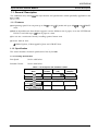
1.1.2.1 Printing Specification
Print Speed :
See the table below.
Printable Column :
See the table below.
Table 1-1 Print Speed and Printable Column
Character
Pitch
I
10 cpi
Print Speed
(LQ)
Printable
Column
I
136
I
150
Print Speed
(DRAFT)
CPS 1
250
12 cpi
163
180
300
15 cpi
204
255
375
17 cpi
I
I ( 1 0 cpi/Condensed) I
233
20 cpi
272
I
I
257
I
I
428
I
300
I
I
I
500
(12 cpi/Condensed)
REV.-A
1-1
ADDENDUM
Stylus-800/1000 SERVICE MANUAL
General Description
1.1.2.2 Paper Handling Specification
Paper Feeding :
■ Friction fed (either from built-in auto sheet feeder or manual insertion slot)
■ push tractor feed (from rear tractor unit (optional))
Note) Set the release lever to correct position to select proper feeding system.
1.1.2.3 Paper Specification
<Cut Sheet>
[With ASFJ
Width :
182-420 mm (7.2 - 16.5”)
Note) When you use A3 size paper in landscape orientation, both left
and right margin area becomes large since the maximum printable
width is limited up to 345 mm.
Length :
Thickness :
Weight :
Quality :
182-297 mm (7.2 - 11.7’)
0.065-0.11 (0.0026 - 0.0043”)
64.90 g/mZ (18 - 241b./55 -78 Kg)
Normal PPC paper,
Bond paper
.
(With manual insertion slot]
182-420 mm (7.2 - 16.5”)
Width :
182-420 mm (7.2 - 16.5”)
Length :
Thickness : 0.065-0.11 (0.0026 - 0.0043”)
52-90 g/m2 (14 - 241b.)
Weight :
Normal PPC paper, Bond paper
Quality :
<Envelope>
Size :
Thickness :
#6 (W X L : 166 X 92 mm (6VZ x 3%”))
#10 (W X L : 240 X 104 mm (9?4 x 4%”))
0.16-0.52 mm (0.0063 - 0.020”)
Note) The variation in thickness within printable area must be less than
0.25 mm (0.0098”).
Weight :
Quality :
45-90 g/m’ (I2 - 241b.)
<Continuous form>
Width :
Thickness :
Weight :
Quality :
101.6 -406.4 mm (4.0 - 16.0”)
0.065 -0.1 mm (0.0026 - 0.0039”)
52-82 g/m2 (14 - 221b.)
Normal PPC paper, Bond paper
cLabel>
Label size : 63.5 x 23.8 mm (W x L/Minimum)
101.6 -406.4 mm (4.0 - 16.0”)
Baclcirw vaver size :
ThiCkn:si :’ Less than 0.2 mm (0.0078”) including backing paper.
Equivalent of normal PPC paper
QuaIity :
Notes) 1.
2.
3.
4.
1-2
Normal PPC paper, Bond paper
Label can only be used under normal temperature condition.
Usable only with tractor feeding (requires optional tractor unit).
Do not perform any reverse feed.
Remove label form paper while the printer is not in use.
REV.-A
ADDENDUM
Stylus-800/1000 SERVICE MANUAL
Adjust lever :
General Description
The adjust lever, attached to the carriage unit, must be set to proper position for the
paper thickness, as shown in table below.
Table 1-2 Adjust Lever Position
Paper
Lever
Position
LEFT
(Horizontal)
Cut Sheet
Continuous form
1
RIGHT
(Vertical)
REV.-A
Envelope
Label
1-3
ADDENDUM
Stylus-800/fOOO SERVICE MANUAL
General Description
1.1.3 Printer
Operations
This section describes the basic operation of the printer.
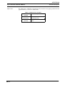
1.1.3.1 Control Panel
The control panel of the Stylus-1000 contains six non-lock type push buttons and nine LED indicators for easy
controls over the various printer’s functions.
() DATA
opApEROuT
Q
O INK OUT
I
1
() ECONOMY
O CONDENSED
[;;
1 II
.
Figure 1-1 Control Panel - Stylus-1000
fButtonl
■ PAUSE
Switch the printer status between the printing and the no-printing in case if
any print data is exist in the input buffer.
■ ECONOMY/CONDENSED Selects the ECONOMY printing mode or the CONDENSED printing mode
alternately. It also works as a reverse micro feed button if the ALT button has
been pressed.
■ FONT
Select the one of the available fonts. It also works as a forward micro feed
button if the ALT button has been pressed.
H LOAD/EJECT
By pressing this button, the printer either loads a new paper into the printer,
or ejects a paper that currently in the paper path of the printer. It also works
as the LF/FF button if the ALT button has been pressed.
■ ALT
It functions as to alternate the function of certain buttons to another. Holds
down this button in PAUSE mode for 5 seconds, the printer moves the carriage
to the ink cartridge installation/replacement position.
■ RESET
When you press this button, the printer is initialized.
[Indicators]
■ PAUSE
It lights when the printer is in PAUSE mode.
It lights when the print data exists in the input buffer.
■ PAPER OUT
It lights when the printer is in out-of-paper condition. It blinks if the paper jam
has occurred.
z INK OUT
It lights when the printer detects ink end of the ink cartridge. It blinks if the
ink level becomes low.
■ ECONOMY/CONDENSED These LEDs shows the currently selected mode.
It indicates the currently selected font.
■ FONT
■ DATA
1-4
REV.-A
ADDENDUM
General Description
StVlus-800/1000 SERVICE MANUAL
1.1.3.2 Default Setting Item
The default setting items of the Stylus-1000 are as listed in table below.
Table 1-3 Default Setting Item
Description
Menu Contents
Character Table
Select the character table
Factory
Setting
us
Italic
Auto Print Direction
Print direction is automatically
selected as to maintains optimal
print quality (alignment).
. . . . . . . . . . . . . . . . . . . . . . . . . . . . . . . . . . . . . . . . . . . . . . . . . . . . . . . . . . . . . . . . . . . . . . . . . . . . . . . . . . . . . . . . . . !. . . . . . . . . . .
OFF: Depends on the command ‘ESC U’.
ON
Page Length for
Continuous Form
o:
11 inch
11 “
1:
2:
12 inch
8.5 inch
3:
70/6 inch
Skip-over Perforation
ON:
ON 10FF
OFF
for
Continuous Form
Note)
REV.-A
Network IIF Mode
ON:
For network environment, such as
LocalTalk. (Time-out printing is
disabled.)
,. !. .., .. ... ,.,. .! , . . . . . . . . . . . . . . . . . . . . . . . . . . . . . . . . . . . . . . . . . . . . . . . . . . . . . . . . . . . . . . . . . . . . . . . . , . ,., ,.,. !
OFF: For normal environment. (Time-out
printing is enabled.)
OFF
Mixed Text/Graphics
Mode ‘1
ON:
To ensure proper’ printing of the
image containing graphics and
scalable font, with certain
applications, such as MS Word,
WordPerfect V.5.1 or earlier.
,., . , . . . , , . . . . . . . . . . . . . . . . . . . . .. . . . . . . . . . . . . . . . . . . . . . . . . . . . . . . . . . . . . . . . . . . . . . . . . . . . . . . . . . . . . . . . .
OFF: For normal use.
OFF
4uto Line Feed
ON:
Line feed operation is automatically
performed by CR code input.
.0. . . . . . . . . . . . . . . . . . . . . . . . . . . . . . . . . . . . . . . . . . . . . . . . . . . . . . . . . . . . . . . . . . . . . . . . . . . . . . . . . . . . . . . . . . . . . . . . . . .
OFF: No line feed operation with single
“CR code.
OFF
Wto IIF Switching
Printer automatically select the l/F
which receives the data.
,,. . . . . . . . . . . . . . . . . . . . . . . . . .. . . . . . . . . . . . . . . . . . . . . . . . . . . . .. ,. ,0.0. .,. . . . . . ., . ,. , ,., , ,., . . . . . .
OFF: Active l/F is depending on the DIPSW setting on the optional l/F card.
ON
hto l/F Switch
Nait Time
30 sec. / 10 sec.
\uto Tear Off
ON:
ON:
Printer automatically feed a paper to
the tear-off position.
,,,. . . . . . . . . . . . . . . . . . . . . . . . . . . . . . . . . . . . . . . . . . . . . . . . . . . . . . . . . . . . . . . . . . . . . . . . . . . . . . . . ,. . . . , . ,. O. .
OFF:
10 sec.
ON
● 1 = If set to ON, the capacity of input buffer is limited to 64 KByte.
1-5
ADDENDUM
Stylus-800/fOOO SERVICE MANUAL
General Description
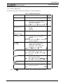
1.1.3.3 Error Conditions
The Stylus-1000 detects various errors and indicates them with the LED indicators and buzzer as shown in
table below.
T de 1-4 El ror Indication
PAPER INK OUT
LED
LED
Error
OFF
O N
Paper out
PAUSE
LED
OFF
Buzzer
Recovery
JJ ■ x 3 times I Set the paper and press the
-
buttons as follows :
1. PAUSE
2. LOAD/EJECT
+
1
Blink
Paper jam
OFF
OFF
Ink low ● 1
OFF
Ink end
No ink
cartridge
Carriage Error
Release Lever
*I
Backout/Eject
Error with
Continuous
form ● 1
Waste ink tank
over-flow
Note) JI :
n :
■ :
❑ :
●1:
‘2 :
1-6
ON
ON
OFF
--tOFF
OFF
T
OFF
OFF
T
OFF
ON
OFF
~m x 3 times
Same as above.
No beeps
Press PAUSE button and replace
the ink cartridge to new one.
Then, press PAUSE button again
to resume r)rintina. ● 2
J= x 3 times
Replace the ink cartridge and
press PAUSE button.
OFF
Install the ink cartridge and press
PAUSE button.
OFF
J3a x 5 times Turn off the printer, and turn it on
again.
OFF
)8 x 3 times Set the release lever to the
I position to current paper path.
OFF
~ x 3 times
BLINKS
-
-
)= x 3 times Service maintenance required.
(Replace the waste ink absorbing
material and reset the protect
counter.)
0.1 second beep
0.5 second beep
0.1 second interval
0.2 second intewal
This is not treated as an error. (Warning)
It is not necessary to immediately replace the ink cartridge until the printer detect ‘Ink End’
error.
REV.-A
ADDENDUM
Operating Principles
Stylus-800/1000 SERVICE MANUAL
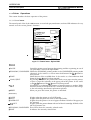
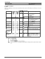
2.1 Operating Principles
The main control circuit of the Stylus-1000 is different from the StyluS-800, and is the C114 MAIN BOARD.
This board has an additional comector to which the optional mpE-B I/F card cm be connected. The figure
below shows a block diagram of the main control circuit board.
;Common
;
: Drive Circuit ~
~ (PWC/PWD) ~
<. . . . . . . . . . . . . . . . . . . . .
—
L
S1 (Data)/LAT
I
L—————.
I
IC3
E05A85EB
1
(Program)
––––––
Head driver
I
(Printhead) I
IC8‘1
IC7•2
lC5/6
Mask ROM
(CG)
Mask ROM
(CG)
PS-RAM
(lM)
CRO-3
r
ADO-15
1
“’’w--=
I-E[
Control
Panel
(C106 PNL)
IC13
SLA7024
QM1
SMA6501
CR Motor
PFMotor
--t
Note) ● 1 : 4MBit Mask - For JAPAIWTAIWAN only
8MBit Mask - For KOREA only
*2 : 16MBit Mask - For JAPANfiAIWAN/KOREA
8Mbit Mask - For Europe
Figure 2-1 C114 MAIN BOARD Block Diagram
2-1
REV.-A
I
ADDENDUM
Stylus-800/1000 SERVICE MANUAL
Operating Principles
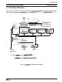
2.1.1 Sensor Circuit
In addition to the sensors built in the C106 MAIN BOARD for the StylUS-8C10, the C114 MAIN BOARD for the
Stylus-1000 is equipped with a sensor which detect the position of the release lever. The release lever is used
to switch between normal paper feed from the built-in ASF and the tractor feed which is ordy available if the
optional tractor unit has been installed. The figure below shows the sensor circuit block diagram.
PE
+5v
RE
(CN4;
+5v
+5V
‘+5V
79 I
SW8
FT@
801
SW7
HP
(CN3)
+!5V
Ink
IC9
INK 4 6
‘W6 E 0 5 A 8 5 E B
I
(IC3)
CPU
(ICI)
AN1
74
,.–. .—
T
+5V
4
! Printhead
‘— . . — .
Figure 2-2 Sensor Circuit Block Diagram
2-2
REV.-A
ADDENDUM
Stylus-800/1000 SERVICE MANUAL
Disassembly and Assembly
3.1 Disassembly and Assembly
This addendum only explains the disassembly and assembly procedures
wtich
specifically applicable to the
Stylus-looo.
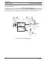
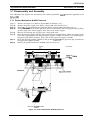
3.1.1 Printer Mechanism M-4860 Removal
[Step 1]
[Step 2]
[Step 3]
[step 4]
[Step 5]
[Step 6]
[Step 71
[Step 8]
Remove the upper case. (Refer to Stylus-800 S/M (Section 3.2.1.))
Remove the power supply unit. (Refer to Stylus-800 S/M (Section 3.2.2.))
Remove themain control circuit board unit. (Refer to Stylus-800 S/M (Section 3.2.3.))
Unhook two hooks of the center support of the auto sheet feeder from a front guide shaft, by lifting
up front edge of the center support. Then, remove the center support.
Remove the retaining ring (E-ring) from a front guide shaft.
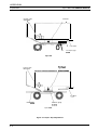
Move the left edge guide assembly to the position shown in figure below, where two cutouts made
to the front paper guide frame (the paper eject support assembly is inserted to a rounded edge of
the paper guide frame assembly). Then, take out the paper exit support assembly.
Move the right edge guide assembly to the position expIained in the previous step and take out
the paper exit support assembly.
Remove the printer mechanism (M-4860) from the lower case.
cutout
‘
Front frame
/
Ill
It
II
guide
bly
Paper eject SUPPOR
assembly
Figure 3-1 Printer Mechanism (M-4860) Removal
REV.-A
3-1
I
ADDENDUM
Stylus-800/1000 SERVICE MANUAL
Disassembly and Assembly
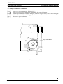
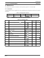
3.1.2 Paper Feed Motor Removal
[Step 1]
[Step 2]
[Step 3]
[Step 4]
Remove the printer mechanism. (Refer to 3.1.1.)
Remove two screws ((CBS M3x1O)X2) which fixing the paper feed motor.
Turn the paper feed motor for about 90 degree, as shown in figure below, so that one of fixing tab
of the motor released from a holding plate.
Take out the paper feed motor.
/
u
I
i
.
“m
(m .,,,.O.’.,. .. ,
‘@
‘o
{/l’fn
N
II
J
Paper Feed Motor
L
Figure 3-2 Paper Feed Motor Removal
.
3-2
REV.-A
ADDENDUM
Disassembly and Assembly
Stylus-800/1000 SERVICE MANUAL
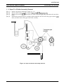
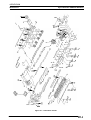
3.1.3 Paper
Feed
Roller Assembly Removal
Remove the printer mechanism. (Refer to 3.1.1.)
Remove the carriage assembly. (Refer to SVIUS-800 S\M (Section 3.2.6.5.)
Remove four screws ((CBB M3x1O)X4, two each at left and right side) and remove the rear base
frame.
Unhook the transmission gear assembly which attached at the left end of the paper ejection roller
shaft, and then remove the paper feed roller assembly.
[Step 1]
[Step 2]
[Step 3]
[Step 4]
I
II
‘(
Figure 3-3 Paper Feed Roller Assembly Removal
3-3
REV.-A
1
ADDENDUM
Adjustment
Stylus-800/1000 SERVICE MANUAL
4.1 Adjustment
This addendum only explains the adjustment procedures which specifically applicable to the Stylus-1000.
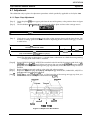
4.1.1 Paper Gap Adjustment
[Step 1]
[Step 2]
■
Insert the plastic plate into a paper path from the rear of the printer, at the position shown in figure
below.
Put the thickness -gauge (#F518 / t=l.Omrn) on the plastic plate and move the carriage onto it.
Certain thick and stiff paper can be used with this adjustment as a substitute for the plastic plate.
[Step 3]
I
Verify that a gap exist between the front edge of the carriage frame and the front frame. The
direction of carriage guide shaft holder rotation is depending on the existence of this gap, as shown
in table below.
YES
t
RIGHT Bush
LEFT Bush
Gap between
Carriage and Front frame
I
NO
(Gap exist between printhead and PG gauge)
Cw
Ccw
I
Ccw
Cw
Note) The direction in table above, is viewed from a side frame to which the corresponding
carriage guide shaft holder is attached.
[Step 4]
[Step 5]
[Step 6]
[Step n
Rotates BUSH, PARALLEL, ADJUST that attached at the left end of the carriage guide shaft as the
printhead contact the PG gauge. When you narrow the gap and the printhead contacts the PG
gauge, the front edge of the carriage unit pop up and if so, moves the bush 1 step in reverse
direction.
Remove the PG gauge and attach it at the right side adjust position.
Repeat the step from [Step 2] to [Step 4], and adjust the gap with BUSH, PARALLEL, ADJUST at
the right end of the carriage guide shaft.
Veri&-the gap at the left atiju~t position, as if the front edge of the carriage unit pop up when you
move the left end bush 1 step in counter-clockwise (CCW).
A@&int (L)
I
Arjua
L?Oilt (F!)
I
/
I
I
I
Frmtframe
stytu’ *OO
!
Slyilu lma
Figure 4-1 Adjust Tool Set Position
REV.-A
4-1
ADDENDUM
Stylus-800/1000 SERVICE MANUAL
Adjustment
Printhead
Carriage guide
shaft holder
/
. . . . . . . . . . . . . . . . . . . . . . . . . . . . . . . . . . . . . . . . . . . . . . . . . . . . . /./. . .’. . . . .. . . . . . . .
\
\
o\ ‘
./
Front frame
PG Adjust gage
#F609
stylus 600
Printhaad
Carriage guide
shaft holder
.......................................................
.........................
rame
Thickness gauge
(1.Omm)
Plastic plate
stylus 1000
Figure 3-2 Paper Gap Adjustment
4-2
.
REV.-A
I
ADDENDUM
Maintenance
Stylus-800/1000 SERVICE MANUAL
6.1 Maintenance
This addendum only explains the maintenance which specifically applicable to the Stylus-1000.
6.1.1 Lubrication
A proper lubricant must be applied only to the specified points of the printer mechanism for optimal
performance.
Table 6-1 Recommended Lubricant
Type
o-5
G-26
Oil
Grease
Note)
Name
QTY
40 cc
40 g
Part No.
1010513
B702600001
Availability
E
E
E = EPSON Exclusive product (Not commercially available)
Table 6-2. Lubrication Points
Ref. No.
Lubrication Point
Lubricant
stylus
800
stylus
1000
(1)
Frame Assembly, R (Gear shaft A,B and C)
G-26
(1 -3 mg)
YES
YES
(2)
Flat gear, 8
G-26
(1 -3 mg)
YES
YES
(3)
Shaft, Reduction
G-26
(1 -3 mg)
YES
-
(4)
Oil Pad (Carriage)
YES
YES
(5)
Shaft, CR, Guide
o-5
(3 drops)
o-5
YES
YES
YES
YES
(Paint on the shaft)
(6)
Roller, PF
G-26
(1 -3 mg)
(7)
Release shaft
G-26
(1 -3 mg)
(8)
Paper Eject Roller Shaft (Ends)
G-26
(1 -3 mg)
(9)
GEAR, 14
G-26
(1 -3 mg)
YES
(lo)
GEAR, 11
G-26
(1 -3 mg)
YES
(11)
Planetary Gear Lever
G-26
(1 -3 mg)
YES
(12)
Front Frame / PG Adjust Lever
G-26
(13)
GEAR, 22.5
G-26
(1 -3 mg)
YES
.
YES
YES
YES
YES
6-1
REV.-A
I
I
ADDENDUM
Stylus-800/1000 SERVICE MANUAL
Maintenance
$2 y’&- -7\J\,,
.
w
Figure 6-1. Lubrication Points
REV.-A
6-2
I
ADDENDUM
APPENDIX
StyhIs-800/1000 SERVICE MANUAL
A.1 Appendix
This addendum only explains the comectors which specifically applicable to the Stylus-1000.
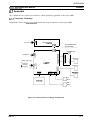
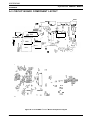
A.1.l Connector Summary
Figure below shows the intercomection between the major components of the Stylus-1000.
c1
z
AC Input
cl 06 PSWPSE
ICN2 ]
I,
Printer Mechanism
(M-4810/4860)
..........................................
[CN7 I
Prnthead Unit
/’
o
z
Parallel l/F
+
HP Sensor
Stylus-1000
,..
—.. — . . only
— .1
. ..7
I
: Optional
Zi
1 TYPE-B
: l/F Card
L.. —.. —.. —..
. .i
+
c1 o6/cl 14
MAIN
I
PE Sensor
b
RE Sensor
0
CI06 PNL
PF
Motor
CR
Motor
Figure A-1 Interconnection of Major Components
A-1
REV.-A
I
ADDENDUM
Stylus-800/1000 SERVICE MANUAL
APPENDIX
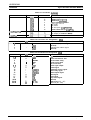
Table A-1 Connector Wmmary
Board
Cl 06/114 MAIN
Location
Pin
CN1
CN2
CN3
CN4
CN5
CN6
CN7
CN8
36 pins
12
12
4
6
5
4
18
Description
Centronics parallel l/F
HEAD-1 (to printhead)
HEAD-2 (to printhead)
PE(#l/2)/RE(#3/4) sensor
PF motor
CR motor
PS line (from C106 PSE/PSB)
Panel control line (to C106 PNL)
C106 PSEVPSE
AC input (UN)
DC output (to C106/114 MAIN)
C106 PNL
(to C106/114 MAIN)
Table A-2 Connector Pin Assignment - CN4
Pin
I
1/0
1
2
3
4
I
I
Name
I
Description
I
Paper-End (PE) status signal
(Ground)
Release lever status signal
(Ground)
PE
GND
LSW
GND
Table A-3 Connector Pin Assignment - CN9
Pin
1-6
7
8
9
10
11
12
13
14
15
16
17
18
19-24
25-28
29-36
.
1/0
o
1
I
o
0
I
I
I
o
0
0
0
1/0
N a m e
+5V
TXD
/READY
RXD
NC
IRST
INH
/CMREQ
/WPRDY
/RDREQ
/WR
/RD
/cs
GND
A3 - AO
D7 - DO
Description
+5V DC
Serial transmission data
Receive data ready
Serial receive data
(No connection)
Reset signal output
Inhibit signal
Command request signal
Write ready signal
Read request signal
Write signal
Read signal
Chip select signal
[Ground)
Address line (A3 - AO)
Data line (D7 - DO)
REV.-A
A-2
I
ADDENDUM
Stylus-800/1000 SERVICE MANUAL
APPENDIX
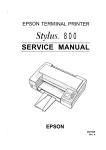
A.3 CIRCUIT BOARD COMPONENT LAYOUT
—
...—i,
I
I
1
I
I
I
.—
u Qrllz rd
Iz
8 CN5 I
~N2t
4
C144
I
12
CN3 1
RHzz
ii
L—J
4MI
VRl
- - - - -
Emr
,7... -.
II
I
I
i:
I
$,
~el:
‘
,72~:
c~s.
~:s= ;-- ,
,.
:
,
98 I
.J
— .-..,
I
1111! 1111[.
Zi
Uq.
-
~:,
i
“
<:
1
. - ”
..,.
. . . ,
.
.
lwz
o
t
o
0 0
0 0
00:
co
;U” ~
Figure A-2. Cl 14 MAIN Control Board Component Layout
REV.-A
A-4
I
EPSON