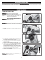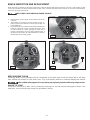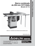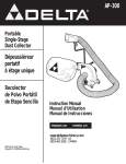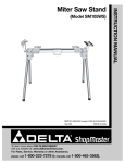
1
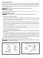
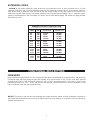
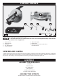
(Model MS250)
PART NO. A05737_01-24-06_RevB
Copyright © 2006 Delta Machinery
To learn more about DELTA MACHINERY
visit our website at: www.deltamachinery.com.
For Parts, Service, Warranty or other Assistance,
please call
ESPAÑOL: PÁGINA 23
1-800-223-7278 (In Canada call 1-800-463-3582).
INSTRUCTION MANUAL
10" Compound
Power Miter Saw
TABLE OF CONTENTS
IMPORTANT SAFETY INSTRUCTIONS . . . . . . . . . . . . . . . . . . . . . . . . . . . . . . . . . . . . . . . . . . . . . . . . . . . . . . . . . . . 2
SAFETY GUIDELINES. . . . . . . . . . . . . . . . . . . . . . . . . . . . . . . . . . . . . . . . . . . . . . . . . . . . . . . . . . . . . . . . . . . . . . . . . 3
GENERAL SAFETY RULES . . . . . . . . . . . . . . . . . . . . . . . . . . . . . . . . . . . . . . . . . . . . . . . . . . . . . . . . . . . . . . . . . . . . 4
ADDITIONAL SPECIFIC SAFETY RULES . . . . . . . . . . . . . . . . . . . . . . . . . . . . . . . . . . . . . . . . . . . . . . . . . . . . . . . . . 5
FUNCTIONAL DESCRIPTION . . . . . . . . . . . . . . . . . . . . . . . . . . . . . . . . . . . . . . . . . . . . . . . . . . . . . . . . . . . . . . . . . . 7
CARTON CONTENTS . . . . . . . . . . . . . . . . . . . . . . . . . . . . . . . . . . . . . . . . . . . . . . . . . . . . . . . . . . . . . . . . . . . . . . . . . 8
ASSEMBLY . . . . . . . . . . . . . . . . . . . . . . . . . . . . . . . . . . . . . . . . . . . . . . . . . . . . . . . . . . . . . . . . . . . . . . . . . . . . . . . . . 8
OPERATION . . . . . . . . . . . . . . . . . . . . . . . . . . . . . . . . . . . . . . . . . . . . . . . . . . . . . . . . . . . . . . . . . . . . . . . . . . . . . . . 11
TROUBLESHOOTING . . . . . . . . . . . . . . . . . . . . . . . . . . . . . . . . . . . . . . . . . . . . . . . . . . . . . . . . . . . . . . . . . . . . . . . 20
MAINTENANCE. . . . . . . . . . . . . . . . . . . . . . . . . . . . . . . . . . . . . . . . . . . . . . . . . . . . . . . . . . . . . . . . . . . . . . . . . . . . . 20
SERVICE . . . . . . . . . . . . . . . . . . . . . . . . . . . . . . . . . . . . . . . . . . . . . . . . . . . . . . . . . . . . . . . . . . . . . . . . . . . . . . . . . . 22
ACCESSORIES . . . . . . . . . . . . . . . . . . . . . . . . . . . . . . . . . . . . . . . . . . . . . . . . . . . . . . . . . . . . . . . . . . . . . . . . . . . . . 22
WARRANTY. . . . . . . . . . . . . . . . . . . . . . . . . . . . . . . . . . . . . . . . . . . . . . . . . . . . . . . . . . . . . . . . . . . . . . . . . . . . . . . . 22
ESPAÑOL. . . . . . . . . . . . . . . . . . . . . . . . . . . . . . . . . . . . . . . . . . . . . . . . . . . . . . . . . . . . . . . . . . . . . . . . . . . . . . . . . . 23
IMPORTANT SAFETY INSTRUCTIONS
Read and understand all warnings and operating instructions before using any tool or equipment.
When using tools or equipment, basic safety precautions should always be followed to reduce the risk of
personal injury. Improper operation, maintenance or modification of tools or equipment could result in serious
injury and property damage. There are certain applications for which tools and equipment are designed. Delta
Machinery strongly recommends that this product NOT be modified and/or used for any application other than
for which it was designed.
If you have any questions relative to its application DO NOT use the product until you have written Delta Machinery
and we have advised you.
Online contact form at www.deltamachinery.com
Postal Mail: Technical Service Manager
Delta Machinery
4825 Highway 45 North
Jackson, TN 38305
(IN CANADA: 125 Mural St. Suite 300, Richmond Hill, ON, L4B 1M4)
Information regarding the safe and proper operation of this tool is available from the following sources:
Power Tool Institute
1300 Sumner Avenue, Cleveland, OH 44115-2851
www.powertoolinstitute.org
National Safety Council
1121 Spring Lake Drive, Itasca, IL 60143-3201
American National Standards Institute, 25 West 43rd Street, 4 floor, New York, NY 10036 www.ansi.org
ANSI 01.1Safety Requirements for Woodworking Machines, and the U.S. Department of Labor regulations www.osha.gov
SAVE THESE INSTRUCTIONS!
2
SAFETY GUIDELINES - DEFINITIONS
It is important for you to read and understand this manual. The information it contains relates to protecting YOUR
SAFETY and PREVENTING PROBLEMS. The symbols below are used to help you recognize this information.
Indicates an imminently hazardous situation which, if not avoided, will result in death or serious injury.
Indicates a potentially hazardous situation which, if not avoided, could result in death or serious injury.
Indicates a potentially hazardous situation which, if not avoided, may result in minor or moderate injury.
Used without the safety alert symbol indicates potentially hazardous situation which, if not avoided, may
result in property damage.
CALIFORNIA PROPOSITION 65
SOME DUST CREATED BY POWER SANDING, SAWING, GRINDING, DRILLING, AND OTHER
CONSTRUCTION ACTIVITIES contains chemicals known to cause cancer, birth defects or other reproductive harm.
Some examples of these chemicals are:
· lead from lead-based paints,
· crystalline silica from bricks and cement and other masonry products, and
· arsenic and chromium from chemically-treated lumber.
Your risk from these exposures varies, depending on how often you do this type of work. To reduce your exposure to
these chemicals: work in a well ventilated area, and work with approved safety equipment, always wear MSHA/NIOSH
approved, properly fitting face mask or respirator when using such tools.
3
GENERAL SAFETY RULES
READ AND UNDERSTAND ALL WARNINGS AND OPERATING INSTRUCTIONS BEFORE
USING THIS EQUIPMENT. Failure to follow all instructions listed below, may result in electric shock,
fire, and/or serious personal injury or property damage.
IMPORTANT SAFETY INSTRUCTIONS
1.
2.
3.
4.
5.
6.
7.
8.
9.
10.
11.
12.
13.
FOR YOUR OWN SAFETY, READ THE INSTRUCTION MANUAL BEFORE OPERATING THE
MACHINE. Learning the machine’s application,
limitations, and specific hazards will greatly
minimize the possibility of accidents and injury.
USE CERTIFIED SAFETY EQUIPMENT. Eye
protection equipment should comply with ANSI
Z87.1 standards, hearing equipment should
comply with ANSI S3.19 standards, and dust
mask protection should comply with MSHA/NIOSH
certified respirator standards. Splinters, air-borne
debris, and dust can cause irritation, injury, and/or
illness.
DRESS PROPERLY. Do not wear tie, gloves, or
loose clothing. Remove watch, rings, and other
jewelry. Roll up your sleeves. Clothing or jewelry
caught in moving parts can cause injury.
DO NOT USE THE MACHINE IN A DANGEROUS
ENVIRONMENT. The use of power tools in damp
or wet locations or in rain can cause shock or
electrocution. Keep your work area well-lit to
prevent tripping or placing arms, hands, and
fingers in danger.
MAINTAIN ALL TOOLS AND MACHINES IN PEAK
CONDITION. Keep tools sharp and clean for best and
safest performance. Follow instructions for lubricating
and changing accessories. Poorly maintained tools and
machines can further damage the tool or machine and/
or cause injury.
CHECK FOR DAMAGED PARTS. Before using the
machine, check for any damaged parts. Check
for alignment of moving parts, binding of moving
parts, breakage of parts, and any other conditions
that may affect its operation. A guard or any other
part that is damaged should be properly repaired
or replaced. Damaged parts can cause further
damage to the machine and/or injury.
KEEP THE WORK AREA CLEAN. Cluttered areas and
benches invite accidents.
KEEP CHILDREN AND VISITORS AWAY. Your shop
is a potentially dangerous environment. Children and
visitors can be injured.
REDUCE THE RISK OF UNINTENTIONAL STARTING.
Make sure that the switch is in the “OFF” position
before plugging in the power cord. In the event
of a power failure, move the switch to the “OFF”
position. An accidental start-up can cause injury.
USE THE GUARDS. Check to see that all guards
are in place, secured, and working correctly to
prevent injury.
REMOVE ADJUSTING KEYS AND WRENCHES
BEFORE STARTING THE MACHINE. Tools, scrap
pieces, and other debris can be thrown at high
speed, causing injury.
USE THE RIGHT MACHINE. Don’t force a machine
or an attachment to do a job for which it was not
designed. Damage to the machine and/or injury
may result.
14.
15.
16.
17.
18.
19.
20.
21.
22.
23.
24.
4
USE RECOMMENDED ACCESSORIES. The
use of accessories and attachments not recommended by Delta may cause damage to the
machine or injury to the user.
USE THE PROPER EXTENSION CORD. Make
sure your extension cord is in good condition.
When using an extension cord, be sure to use one
heavy enough to carry the current your product will
draw. An undersized cord will cause a drop in line
voltage, resulting in loss of power and overheating.
See the Extension Cord Chart for the correct size
depending on the cord length and nameplate
ampere rating. If in doubt, use the next heavier
gauge. The smaller the gauge number, the heavier
the cord.
SECURE THE WORKPIECE. Use clamps or a vise to
hold the workpiece when practical. Loss of control
of a workpiece can cause injury.
FEED THE WORKPIECE AGAINST THE DIRECTION
OF THE ROTATION OF THE BLADE, CUTTER, OR
ABRASIVE SURFACE. Feeding it from the other
direction will cause the workpiece to be thrown out
at high speed.
DON’T FORCE THE WORKPIECE ON THE
MACHINE. Damage to the machine and/or injury
may result.
DON’T OVERREACH. Loss of balance can make
you fall into a working machine, causing injury.
NEVER STAND ON THE MACHINE. Injury could occur
if the tool tips, or if you accidentally contact the cutting
tool.
NEVER LEAVE THE MACHINE RUNNING UNATTENDED. TURN THE POWER OFF. Don’t leave the machine
until it comes to a complete stop. A child or visitor could
be injured.
TURN THE MACHINE “OFF”, AND DISCONNECT
THE MACHINE FROM THE POWER SOURCE before
installing or removing accessories, before adjusting
or changing set-ups, or when making repairs. An
accidental start-up can cause injury.
MAKE YOUR WORKSHOP CHILDPROOF
WITH PADLOCKS, MASTER SWITCHES, OR
BY REMOVING STARTER KEYS. The accidental
start-up of a machine by a child or visitor could
cause injury.
STAY ALERT, WATCH WHAT YOU ARE DOING,
AND USE COMMON SENSE. DO NOT USE THE
MACHINE WHEN YOU ARE TIRED OR UNDER
THE INFLUENCE OF DRUGS, ALCOHOL, OR
MEDICATION. A moment of inattention while
operating power tools may result in injury.
THE DUST GENERATED by certain woods and
wood products can be injurious to your health.
Always operate machinery in well-ventilated areas,
and provide for proper dust removal. Use wood
dust collection systems whenever possible.
ADDITIONAL SPECIFIC SAFETY RULES
FAILURE TO FOLLOW THESE RULES MAY RESULT IN SERIOUS PERSONAL INJURY.
1.
2.
3.
4.
5.
6.
7.
8.
9.
10.
11.
12.
13.
14.
15.
16.
DO NOT OPERATE THIS MACHINE until it is
completely assembled and installed according to the
instructions. A machine incorrectly assembled can
cause serious injury.
OBTAIN ADVICE from your supervisor, instructor,
or another qualified person if you are not thoroughly
familiar with the operation of this machine. Knowledge
is safety.
FOLLOW ALL WIRING CODES and recommended
electrical connections to prevent shock or
electrocution.
SECURE THE MACHINE TO A SUPPORTING SURFACE.
Vibration can possibly cause the machine to slide,
walk, or tip over, causing serious injury.
USE ONLY CROSSCUT SAW BLADES. Use only
zero-degree or negative hook angles when using
carbide-tipped blades. Do not use blades with deep
gullets. These can deflect and contact the guard, and
can cause damage to the machine and/or serious
injury.
USE ONLY BLADES OF THE CORRECT SIZE AND
TYPE specified for this tool to prevent damage to the
machine and/or serious injury.
USE A SHARP BLADE. Check the blade to see if it
runs true and is free from vibration. A dull blade or
a vibrating blade can cause damage to the machine
and/or serious injury.
INSPECT BLADE FOR CRACKS or other damage
prior to operation. A cracked or damaged blade can
come apart and pieces can be thrown at high speeds,
causing serious injury. Replace cracked or damaged
blades immediately.
CLEAN THE BLADE AND BLADE FLANGES prior to
operation. Cleaning the blade and flanges allows you
to check for any damage to the blade or flanges. A
cracked or damaged blade or flange can come apart
and pieces can be thrown at high speeds, causing
serious injury.
USE ONLY BLADE FLANGES specified for this tool
to prevent damage to the machine and/or serious
injury.
CLEAR THE AREA OF FLAMMABLE LIQUIDS and/
or gas prior to operation. Sparks can occur that would
ignite the liquids and cause a fire or an explosion.
CLEAN THE MOTOR AIR SLOTS of chips and
sawdust. Clogged motor air slots can cause the
machine to overheat, damaging the machine and
possibly causing a short which could cause serious
injury.
TIGHTEN THE TABLE CLAMP HANDLE and any
other clamps prior to operation. Loose clamps can
cause parts or the workpiece to be thrown at high
speeds.
NEVER START THE TOOL with the blade against the
workpiece. The workpiece can be thrown, causing
serious injury.
KEEP ARMS, HANDS, AND FINGERS away from the
blade to prevent severe cuts. Clamp all workpieces
that would cause your hand to be in the “Table
Hazard Zone” (within the red lines).
WHEN CUTTING WITH A COMPOUND SLIDING
MITER SAW, PUSH THE SAW FORWARD (AWAY
FROM YOU) and toward the fence. Pulling the saw
toward you can cause the saw to kick upward and
toward you.
17.
18.
19.
20.
21.
22.
23.
24.
25.
26.
27.
28.
29.
30.
32.
33.
WHEN USING A SLIDING MITER SAW AS A REGULAR
MITER SAW, LOCK THE SLIDE MECHANISM IN PLACE.
If the slide mechanism is not locked, the saw can kick
back toward you.
ALLOW THE MOTOR TO COME TO FULL SPEED
prior to starting cut. Starting the cut too soon can
cause damage to the machine or blade and/or
serious injury.
NEVER REACH AROUND or behind the saw blade.
A moving blade can cause serious injury.
NEVER CUT FERROUS METALS or masonry. Either
of these can cause the carbide tips to fly off the blade
at high speeds causing serious injury.
NEVER CUT SMALL PIECES. Cutting small pieces
can cause your hand to move into the blade, resulting
in serious injury.
NEVER LOCK THE SWITCH in the “ON” position.
Setting up the next cut could cause your hand to
move into the blade, resulting in severe injury.
NEVER APPLY LUBRICANT to a running blade.
Applying lubricant could cause your hand to move
into the blade, resulting in serious injury.
DO NOT PERFORM FREE-HAND OPERATIONS.
Hold the work firmly against the fence and table.
Free-hand operations on a miter saw could cause
the workpiece to be thrown at high speeds, causing
serious injury. Use clamps to hold the work when
possible.
AFTER COMPLETING CUT, release power switch
and wait for coasting blade to come to a complete
stop before returning saw to raised position. A
moving blade can cause serious injury.
TURN OFF THE MACHINE and allow the blade to
come to a complete stop prior to cleaning the blade
area or removing debris in the path of the blade. A
moving blade can cause serious injury.
TURN OFF MACHINE and allow the blade to come
to a complete stop before removing or securing
workpiece, changing workpiece angle, or changing
the angle of the blade. A moving blade can cause
serious injury.
PROPERLY SUPPORT LONG OR WIDE WORKPIECES. Loss of control of the workpiece can cause
injury.
NEVER PERFORM LAYOUT, ASSEMBLY, OR SET-UP
WORK on the table/work area when the machine is
running. A sudden slip could cause a hand to move
into the blade. Severe injury can result.
TURN THE MACHINE “OFF”, disconnect the machine
from the power source, and clean the table/work area
before leaving the machine. LOCK THE SWITCH IN
THE “OFF” POSITION to prevent unauthorized use.
Someone else might accidentally start the machine
and cause injury to themselves.
BEFORE OPERATING THE SAW, check and securely
lock the bevel, miter, and sliding fence adjustments.
ADDITIONAL INFORMATION regarding the safe
and proper operation of power tools (i.e. a safety
video) is available from the Power Tool Institute, 1300
Sumner Avenue, Cleveland, OH 44115-2851 (www.
powertoolinstitute.com). Information is also available
from the National Safety Council, 1121 Spring Lake
Drive, Itasca, IL 60143-3201. Please refer to the
American National Standards Institute ANSI 01.1
Safety Requirements for Woodworking Machines and
the U.S. Department of Labor regulations.
SAVE THESE INSTRUCTIONS.
Refer to them often and use them to instruct others.
5
POWER CONNECTIONS
A separate electrical circuit should be used for your machines. This circuit should not be less than #12 wire and should
be protected with a 20 Amp time lag fuse. If an extension cord is used, use only 3-wire extension cords which have
3-prong grounding type plugs and matching receptacle which will accept the machine’s plug. Before connecting the
machine to the power line, make sure the switch (s) is in the “OFF” position and be sure that the electric current is of
the same characteristics as indicated on the machine. All line connections should make good contact. Running on low
voltage will damage the machine.
Do not expose the machine to rain or operate the machine in damp locations.
MOTOR SPECIFICATIONS
Your machine is wired for 120 volts, 60 HZ alternating current. Before connecting the machine to the power source,
make sure the switch is in the “OFF” position.
GROUNDING INSTRUCTIONS
This machine must be grounded while in use to protect the operator from electric shock.
1. All grounded, cord-connected machines:
In the event of a malfunction or breakdown, grounding provides a path of least resistance for electric current to
reduce the risk of electric shock. This machine is equipped with an electric cord having an equipment-grounding
conductor and a grounding plug. The plug must be plugged into a matching outlet that is properly installed and
grounded in accordance with all local codes and ordinances.
Do not modify the plug provided - if it will not fit the outlet, have the proper outlet installed by a qualified electrician.
Improper connection of the equipment-grounding conduc-tor can result in risk of electric shock. The conductor
with insulation having an outer surface that is green with or without yellow stripes is the equipment-grounding
conductor. If repair or replacement of the electric cord or plug is necessary, do not connect the equipmentgrounding conductor to a live terminal.
Check with a qualified electrician or service personnel if the grounding instructions are not completely
understood, or if in doubt as to whether the machine is properly grounded.
Use only 3-wire extension cords that have 3-prong grounding type plugs and matching 3-conductor receptacles that
accept the machine’s plug, as shown in Fig. A.
Repair or replace damaged or worn cord immediately.
2. Grounded, cord-connected machines intended for use on a supply circuit having a nominal rating less
than 150 volts:
If the machine is intended for use on a circuit that has an outlet that looks like the one illustrated in Fig. A, the
machine will have a grounding plug that looks like the plug illustrated in Fig. A. A temporary adapter, which looks
like the adapter illustrated in Fig. B, may be used to connect this plug to a matching 2-conductor receptacle as
shown in Fig. B if a properly grounded outlet is not available. The temporary adapter should be used only until
a properly grounded outlet can be installed by a qualified electrician. The green-colored rigid ear, lug, and the
like, extending from the adapter must be connected to a permanent ground such as a properly grounded outlet
box. Whenever the adapter is used, it must be held in place with a metal screw.
NOTE: In Canada, the use of a temporary adapter is not permitted by the Canadian Electric Code.
In all cases, make certain that the receptacle in question is properly grounded. If you are not sure,
have a qualified electrician check the receptacle.
GROUNDED OUTLET BOX
GROUNDED OUTLET BOX
GROUNDING MEANS
CURRENT
CARRYING
PRONGS
ADAPTER
GROUNDING BLADE
IS LONGEST OF THE 3 BLADES
Fig. A
Fig. B
6
EXTENSION CORDS
Use proper extension cords. Make sure your extension cord is in good condition and is a 3-wire
extension cord which has a 3-prong grounding type plug and matching receptacle which will accept the machine’s
plug. When using an extension cord, be sure to use one heavy enough to carry the current of the machine. An
undersized cord will cause a drop in line voltage, resulting in loss of power and overheating. Fig. D-1 shows the correct
gauge to use depending on the cord length. If in doubt, use the next heavier gauge. The smaller the gauge number,
the heavier the cord.
MINIMUM GAUGE EXTENSION CORD
RECOMMENDED SIZES FOR USE WITH STATIONARY ELECTRIC MACHINES
Ampere
Rating
Volts
Total Length
of Cord in Feet
Gauge of
Extension Cord
0-6
0-6
0-6
0-6
120
120
120
120
up to 25
25-50
50-100
100-150
18 AWG
16 AWG
16 AWG
14 AWG
6-10
6-10
6-10
6-10
120
120
120
120
up to 25
25-50
50-100
100-150
18 AWG
16 AWG
14 AWG
12 AWG
10-12
10-12
10-12
10-12
120
120
120
120
up to 25
25-50
50-100
100-150
16 AWG
16 AWG
14 AWG
12 AWG
12-16
12-16
12-16
120
120
120
up to 25
25-50
14 AWG
12 AWG
GREATER THAN 50 FEET NOT RECOMMENDED
Fig. B
FUNCTIONAL DESCRIPTION
FOREWORD
Delta ShopMaster Model MS250 is a 10" Compound Power Miter Saw designed to cut wood, plastic, and aluminum.
Compound angle and bevel cutting are easy and accurate. It can crosscut up to 5-3/4" x 2-3/8", miter at 45° both left
and right up to 4-1/8" x 2-3/8", bevel at 45° left up to 5-7/8" x 1-9/16", and compound 45° x 45°,4-1/8" x 1-9/16". It has
positive miter stops at 0°, 22.5°, 31.62°, and 45° both left and right, and bevel stops at 0° and 45° adjustable. A dust
bag is included to catch fine dust and wood chips.
NOTICE: The photo on the manual cover illustrates the current production model. All other illustrations contained in
the manual are representative only and may not depict the actual color, labeling, or accessories, and are intended to
illustrate technique only.
7
CARTON CONTENTS
1
2
5
4
6
7
3
8
Fig. 1
Remove the miter saw and all loose items from the carton.
Do not lift the miter saw by the switch handle. This action can cause misalignment. Always lift the machine
by the base or the carrying handle.
1.
2.
3.
4.
5.
Miter Saw Arm
Miter Saw Base
Dust Bag
1/2" Blade Wrench
5mm Hex Wrench
6.
7.
8.
Table Lock Handle
Bevel Pointer
M5x.8x10mm Pan Head Screw with an
M5.3 Flat Washer
UNPACKING AND CLEANING
Carefully unpack the machine and all loose items from the shipping container(s). Remove the protective coating from all unpainted
surfaces. This coating may be removed with a soft cloth moistened with kerosene (do not use acetone, gasoline or lacquer thinner for
this purpose). After cleaning, cover the unpainted surfaces with a good quality household floor paste wax.
ASSEMBLY
ASSEMBLY TOOLS REQUIRED
(Supplied)
* 5mm hex wrench
* 1/2” Blade wrench
(Not supplied)
* Phillips head screw driver
* A square to make adjustments
ASSEMBLY TIME ESTIMATE
Assembly time for this product will be about 30 minutes.
8
For your own safety, do not connect the machine to the power source until the machine is completely
assembled and you read and understand the entire instruction manual.
ATTACHING THE MITER SAW ARM TO THE BASE
DISCONNECT MACHINE FROM POWER SOURCE!
1.
2.
Align the bevel lock handle screw (A) Fig. 2 on the miter saw
arm with the bevel hub (B) on the base.
Thread the bevel lock handle screw (A) Fig. 2 into the bevel
hub (B) by turning the bevel handle knob (K) Fig. 3.
B
A
K
Fig. 2
ATTACHING THE BEVEL POINTER
DISCONNECT MACHINE FROM POWER SOURCE!
1.
Loosen the bevel lock handle (K) Fig. 3, and tilt the miter saw
arm to the 45 degree position.
2. Align the hole in the bevel pointer (C) Fig. 3 with the hole (D)
in the back of the base.
3. Insert the M5x.8x10mm pan head screw with washer (B)
Fig. 3 through the hole in the bevel pointer (C). Thread the
screw into the hole (D) in the back of the base and tighten
securely.
NOTE: To adjust the pointer, see the section “ADJUSTING 90°
AND 45° BEVEL STOPS”.
D
C
B
K
Fig. 3
ATTACHING THE TABLE LOCK HANDLE
B
Thread the table lock handle (A) Fig. 4 into the threaded hole (B)
of the arm bracket.
A
Fig. 4
ROTATING THE TABLE TO THE 90° DEGREE POSITION
B
1.
Turn the table lock handle (A) Fig. 5 counter-clockwise one
or two turns, and depress the index lever (B) to release the
45° positive stop.
Fig. 5
9
A
2.
Rotate the table to the left until the index stop engages
with the 90° positive stop (Fig. 6). Tighten the table lock
handle (A).
A
Fig. 6
MOVING CUTTINGHEAD TO THE UP POSITION
1.
2.
Push down on handle (A), Inset, Fig. 7. Pull out the cuttinghead lock knob (B).
Move the cuttinghead (C) to the up position (Fig. 8).
C
A
B
Fig. 7
Fig. 8
A
ATTACHING THE DUST BAG
Squeeze the spring clips (A) Fig. 9 of the dust bag (B) and clip
the dust bag (B) over the ribs of the dust chute.
B
Fig. 9
FASTENING THE MACHINE TO A SUPPORTING SURFACE
A
Before operating your compound miter saw, make sure that it
is firmly mounted to a sturdy workbench or other supporting
surface. Four holes are provided, two of which are shown at
(A) Fig. 10.
When frequently moving the saw from place to place, mount
the saw on a 3/4" piece of plywood, and clamp the plywood
to a supporting surface with “C” clamps.
Fig. 10
10
OPERATION
OPERATIONAL CONTROLS AND ADJUSTMENTS
TABLE HAZARD AREA
A
The area inside the two red lines (A) Fig. 11
on the table is designated as a hazard zone. Never place
your hands inside this area while the machine is running.
B
Fig. 11
USING THE OPTIONAL WORK CLAMP
1.
2.
An optional work clamp (A) Fig. 12 is available. Use this
accessory clamp, especially with short workpieces. Never
allow your hands to be in the “Hazard Zone”.
Two holes (B) Fig. 11 are provided in the base of the miter
saw, enabling you to use the clamp (A) Fig. 12 on either
the right or left hand side of the saw blade.
Keep your hands out of path of saw blade.
If necessary, clamp the workpiece in place before making
the cut.
A
Fig. 12
STARTING AND STOPPING THE MITER SAW
To start the miter saw, depress the switch trigger (A) Fig. 13. To stop the miter saw, release the switch trigger.
This saw is equipped with an automatic electric blade brake. As soon as the switch trigger (A) Fig. 13, is released, the electric brake
is activated and stops the blade in seconds.
A turning saw blade can be dangerous. After completing cut, release switch trigger (A) Fig. 13, to activate
blade brake. Keep cuttinghead down until blade has come to a complete stop.
The torque developed during braking may loosen the arbor screw (E) Fig. 47. The arbor screw should be checked
periodically and tightened if necessary.
LOCKING THE SWITCH IN THE “OFF” POSITION
IMPORTANT: When the miter saw is not in use, the switch should be locked in the "OFF" position using a padlock (B)
Fig. 14, with a 3/16" diameter shackle to prevent unauthorized use of the saw.
B
A
Fig. 13
Fig. 14
11
ROTATING THE TABLE FOR MITER CUTTING
Your miter saw will cut any angle from a straight 90° cut to 47° right and left. Turn the lock handle (A) Fig. 15 counter-clockwise one
or two turns, depress the index lever (B), and move the control arm to the desired angle. Tighten the lock handle (A).
The miter saw is equipped with positive stops at the 0°, 22.5°, 31.62°, and 45° right and left positions. Loosen the lock handle (A) Fig.
15, and move the control arm until the bottom of the index lever (B) engages into one of the positive stops, four of which are shown
at (C). Tighten the lock handle (A). To disengage the positive stop, depress the index lever (B).
A triangle indicator (D) Fig. 17 is provided on the miter scale at the 31.62° right and left miter positions for cutting crown moulding.
(Refer to the “CUTTING CROWN MOULDING” section of this manual).
IMPORTANT: Always tighten the lock handle (A) Fig. 16 before cutting.
A
B
C
A
Fig. 15
Fig. 16
POINTER AND SCALE
The pointer (E) Fig. 17 indicates the angle of cut. Each line on the scale (F) represents 1 degree. When you move the pointer from
one line to the next on the scale, you change the angle of cut by 1 degree.
ADJUSTING THE POINTER
To adjust the pointer (E) Fig. 18, loosen the screw (G), adjust the pointer (E), and tighten the screw.
F
D
E
E
G
Fig. 17
Fig. 18
LOCKING THE CUTTINGHEAD IN THE DOWN POSITION
A
To transport the saw, always lock the cuttinghead in the down
position. Lower the cuttinghead (A) Fig. 19, and push the
cuttinghead lock knob (B) into the hole in the cutting arm until it
locks the cuttinghead.
IMPORTANT: Carrying the machine by the switch handle will
cause misalignment. Always lift the machine by the base or
by the carrying handle (See Fig. 22).
B
Fig. 19
12
TILTING THE CUTTINGHEAD FOR BEVEL CUTTING
You can tilt the cuttinghead of your compound miter saw to cut
any bevel angle from a 90° straight cut off to a 45° left bevel
angle. Loosen the bevel lock handle (A) Fig. 20, tilt the cutting
arm (B) to the desired angle, and tighten the lock handle (A).
B
Positive stops are provided to rapidly position the saw blade
at 90° and 45° to the table. Refer to the section of this manual
titled “ADJUSTING 90° AND 45° BEVEL STOPS.” The bevel
angle of the cuttinghead is determined by the position of the
pointer (C) Fig. 20 on the scale (D).
A
C
A triangle indicator is provided on the bevel scale at the
33.86° bevel angle for cutting crown moulding. Refer to the
“CUTTING CROWN MOULDING” section of this manual.
D
Fig. 20
REAR SUPPORT/CARRYING HANDLE
A rear support bar (A) Fig. 21 is provided to prevent the machine from tipping to the rear when the cuttinghead returns to the up
position. For maximum support, pull the bar (A) out as far as possible.
You can also use the support bar (A) Fig. 22 to carry the machine.
A
A
Fig. 22
Fig. 21
ADJUSTING THE BLADE PARALLEL TO THE TABLE SLOT
DISCONNECT MACHINE FROM POWER SOURCE!
C
1.
Lower the cutting arm. The saw blade (A) Fig. 23 should be
parallel to the left edge (B) of the table opening.
2.
To adjust, loosen the three bolts (C) Fig. 23 and move the
cutting arm until the blade is parallel with the left edge (B)
of the table opening and centered in the slot. Tighten the
three bolts (C).
A
Fig. 23
13
B
ADJUSTING THE FENCE 90° TO THE BLADE
DISCONNECT MACHINE FROM POWER SOURCE!
If the fence (A) Fig. 24 is removed from the saw, adjust it after replacement so that it is 90° to the blade.
1.
Place one end of the square (B) Fig. 24 against the fence (A) and the other end against the blade.
2.
To adjust, loosen the four screws (C) Fig. 25, and adjust fence 90° degrees to the blade. Tighten the four screws (C).
B
A
C
Fig. 25
Fig. 24
ADJUSTING THE DOWNWARD TRAVEL OF THE SAW BLADE
DISCONNECT MACHINE FROM POWER SOURCE!
1.
You can limit the downward travel of the saw blade to
prevent it from contacting any metal surfaces of the
machine. Make this adjustment by loosening the locknut
(A) Fig. 26 and turning the adjusting screw (B) in or out.
2.
Lower the blade as far as possible. Rotate the blade by
hand to make certain the teeth do not contact any metal
surfaces.
3.
Tighten the locknut (A)
B
A
Fig. 26
ADJUSTING 90° AND 45° BEVEL STOPS
DISCONNECT MACHINE FROM POWER SOURCE!
1.
2.
3.
Loosen the bevel lock handle (A) Fig. 20 and move the cutting arm (B) Fig. 20 all the way to the right. Tighten the bevel lock
handle.
Place one end of a square (A) Fig. 27 on the table and the other end against the blade. Check to see if the blade is 90° to the
table (Fig. 27).
To adjust, loosen the locknut (B) Fig. 28, and turn the screw (C) until the head of the screw (C) contacts the casting (D) when
blade is 90° degrees to the table. Tighten the locknut (B).
D
C
A
B
Fig. 28
Fig. 27
14
S
4.
5.
Loosen the bevel lock handle. Move the cutting arm all the
way to the left bevel position and tighten the bevel lock
handle.
Use a combination square (A) Fig. 29 to see if the blade is
at 45° to the table.
A
Fig. 29
6.
7.
8.
To adjust, loosen the locknut (E) Fig. 30, and turn the screw (F) until it contacts the casting (G). Tighten the locknut (E).
Check to see that the bevel pointer (P) Fig. 31 is pointing to the 45° mark on the bevel scale (S) Fig. 29. To adjust the bevel
pointer (P) Fig. 31, loosen the screw (H) and adjust pointer (P). Tighten the screw (H) securely.
These positive stops enable you to rapidly position the blade at the 90° and 45° bevel angle to the table.
H
F
P
G
E
Fig. 31
Fig. 30
ADJUSTING THE TENSION OF THE CUTTINGHEAD RETURN SPRING
DISCONNECT MACHINE FROM POWER SOURCE!
The tension of the cuttinghead return spring was adjusted
at the factory so that the cuttinghead returns to the "up"
position after cutting.
B
To adjust the spring tension, loosen the locknut (A) Fig.
32 and turn the screw (B) (clockwise to increase or
counterclockwise to decrease the spring tension). After
adjustment, tighten the locknut (A).
A
Fig. 32
15
MACHINE USE
TYPICAL OPERATIONS AND HELPFUL HINTS
1.
2.
Before cutting, make certain that the cutting arm and table are at their correct settings and firmly locked in place.
Place the workpiece on the table and hold or clamp it firmly against the fence. The optional clamp (A) Fig. 33 can also be used
on the right side of the machine (See Fig. 11).
3.
If the position or size of the workpiece causes your hand to be in the “Hazard Zone”, use the work clamp
to secure the workpiece. Keep your hands out of the “Hazard Zone”.
4.
5.
For best results, cut at a slow, even cutting rate.
Never attempt freehand cutting (wood that is not held firmly against the fence and table).
AUXILIARY WOOD FENCE
When performing multiple or repetitive operations that result in small cut-off pieces (one inch or less), the
saw blade can catch the cut-off pieces and project them out of the machine or into the blade guard and housing, causing
damage or injury. To limit the risk, mount an auxiliary wood fence on your saw (Fig. 34).
Holes are provided in the fence to attach an auxiliary fence (A) Fig. 34. This auxiliary fence is constructed of straight wood
approximately 1/2" thick by 3" high by 20" long.
NOTE: The auxiliary fence (A) is used ONLY with the saw blade in the 0° bevel position (90° to the table). When you bevel cut (blade
tilted), remove the auxiliary fence.
A
A
Fig. 33
Fig. 34
16
A
GENERAL CUTTING OPERATIONS
1.
2.
3.
4.
5.
Your machine has the capacity to cut standard 2 x 4’s, lying flat or on edge, at the 45° right and left miter angles (Fig. A1 & A2).
A standard 2 x 6 can be cut in the 90° straight cut-off position in one pass (Fig. A3).
Cutting a standard 4 x 4 can be accomplished with one pass (Fig. A4).
This machine has the capacity to accurately cut crown mouldings and other bevel-type cuts (Fig. A5).
Cutting various sizes of plastic pipe is an easy job with this machine (Fig. A6).
A1
A2
A3
A4
A5
A5
17
CUTTING ALUMINUM
Aluminum extrusions such as used for making aluminum screens and storm windows can easily be cut with
your compound
miter saw. When cutting aluminum extrusions, or other sections that can be cut with a saw blade and are within the capacity of
the machine, position the material so the blade is cutting through the smallest cross-section (Fig. 35). The wrong way to cut
aluminum angles is illustrated in Fig. 36. Be sure to apply a stick wax to the blade before cutting aluminum stock. This stick wax is
available at most industrial mill supply houses. The wax provides proper lubrication and keeps chips from adhering to the blade.
NEVER APPLY LUBRICANT TO THE BLADE WHILE THE MACHINE IS RUNNING.
BLADE
FENCE
BLADE
FENCE
Fig. 35
RIGHT
WRONG
Fig. 36
CUTTING BOWED MATERIAL
Check to see if your workpiece is bowed. If it is, make sure the material is positioned on the table as shown in Fig. 37.
If the material is positioned the wrong way, as shown in Fig. 38, the workpiece will pinch the blade near the completion of the cut.
WRONG
RIGHT
Fig. 37
Fig. 38
WORK SUPPORT EXTENSIONS
C
For support when cutting long pieces, a work support extension
can be constructed. Fig. 39 illustrates the miter saw mounted
to two standard 2 x 4’s (A). Fasten the four mounting legs (two
of which are shown at (B) Fig. 39 to the 2 x 4’s, using four
screws (not supplied) through the four holes in the mounting
legs. The length of the 2 x 4’s (A) can vary, depending on the
kind of work that will need to be cut.
C
A
NOTE: Ensure that the top of the support 2 x 4’s (C) are
level with the miter saw table.
B
This is critical because the distance from the top of the
2 x 4’s (A) to the miter saw table varies from saw to saw. In
most cases, standard 2 x 4’s (C) can used. If these are too
high, cut the 2 x 4s (C) to provide this height or use other
properly-sized wood.
Fig. 39
18
CUTTING CROWN MOULDING
One of the many features of the saw is the ease of cutting crown moulding. The following is an example of cutting both inside and
outside corners on 52°/38° wall angle crown moulding.
1. Move the table to the 31.62° right miter position and lock the table in position. NOTE: A positive stop is provided to find this angle
quickly.
2. Tilt the saw blade to the 33.86° left bevel position and tighten bevel lock handle. NOTE: A triangle indicator is provided on the
bevel scale to find this angle quickly.
3. Place the crown moulding on the table with the CEILING EDGE of the moulding against the fence, and make the cut, as shown
in Fig. 40.
NOTE: The piece of crown moulding used for the outside corner will always be on the right hand side of the blade, as shown at (A)
Fig. 40. The piece of crown moulding used for the inside corner will always be on the left hand side of the blade, as shown at
(B) Fig. 40.
4. To make the matching halves of the inside and outside corners, rotate the table to the 31.62° left miter position.
NOTE: A positive stop is provided to find this angle quickly. The saw blade is already tilted to the 33.86° left bevel position from the
previous cut.
5. Place the crown moulding on the table with the WALL EDGE of the crown moulding against the fence and make the cut. Again,
the piece of crown moulding used for the outside corner will always be on the right side of the blade, as shown at (C) Fig. 41. The
piece of crown moulding used for the inside corner will always be on the left side of the blade, as shown at (D) Fig. 41.
6. Fig. 42 illustrates the two outside corner pieces; (A) being the piece cut at (A) Fig. 40 and (C) being the piece cut at (C) Fig. 41.
7. Fig. 43 illustrates the two inside corner pieces; (B) being the piece cut at (B) Fig. 40, and (D) being the piece cut at (D) Fig. 41.
45-45 CROWN MOULDING
NOTE: If you are cutting crown moulding that is 45°-45°, follow the same procedure above, with the exception that the bevel position
will always be at 30° and the miter position will be 35-1/4° to the right or left.
OTHER ANGLES
NOTE: The above instructions are assuming the angle between the walls is 90°. If you need help cutting crown moulding set at angles
other than 90°, see the instruction sheet “CUTTING CROWN MOULDING” on the Delta Machinery web site at www.deltamachinery.
com.
WALL
EDGE
B
A
C
D
CEILING
EDGE
Fig. 41
Fig. 40
C
B
A
Fig. 42
Fig. 43
19
D
TROUBLESHOOTING
For assistance with your machine, visit our website at www.deltamachinery.com for a list of service centers or call the
DELTA Machinery help line at 1-800-223-7278 (In Canada call 1-800-463-3582).
MAINTENANCE
CHANGING THE BLADE
Use only cross-cutting saw blades.
A
When using carbide-tipped blades, do not
use blades with deep gullets as they can
deflect and contact the guard.
B
Use only 10" diameter saw blades which are
rated for 5200 rpm or higher and have 5/8"
diameter arbor holes.
Fig. 44
DISCONNECT MACHINE FROM POWER SOURCE!
B
1.
Remove screw (A) Fig. 44 and rotate cover (B) to the rear
(Fig. 45).
Fig. 45
C
2.
3.
4.
5.
6.
To remove the saw blade, insert the hex wrench (C)
Fig. 46 into the hex hole located on the rear end of the
motor shaft to keep the shaft from turning.
Use a wrench (G) Fig. 47 to loosen the arbor screw (E) by
turning it clockwise.
Remove the arbor screw (E) Fig. 47, the outside blade
flange (F), and the saw blade from the saw arbor.
Attach the new saw blade making certain that the teeth
of the saw blade are pointing down (Fig. 47). Place the
outside blade flange (F) Fig. 45 on the arbor, and attach
the arbor screw (E) by turning it counter-clockwise using
the wrench (G) Fig. 45. At the same time, use the hex
wrench (C) Fig. 46 to keep the arbor from turning.
Rotate the cover back to the front and replace the screw
that was removed in STEP 1.
Fig. 46
E
G
B
Remove wrenches (C) Fig. 46 and (G) Fig. 47
before starting machine.
Fig. 47
20
T
E
E
T
H
BRUSH INSPECTION AND REPLACEMENT
Brush life varies. It depends on the load on the motor. Check the brushes after the first 50 hours of use for a new machine or after
a new set of brushes has been installed. After the first check, examine them after about 10 hours of use until a replacement is
necessary. To inspect the brushes:
DISCONNECT MACHINE FROM POWER SOURCE!
1.
2.
3.
Remove three screws (A) Fig. 48 and remove the motor
cover (B).
The brushes are located in the two holders (C) Fig. 47.
Remove spade type terminal connector (D) and pull out
brush holders (C).
Fig. 50 illustrates one of the brushes (E) removed from the
holder (C). When the carbon on either brush (E) is worn
to 3/16" in length or if either spring (F) or shunt wire is
burned or damaged in any way, replace both brushes. If
the brushes are found to be serviceable after re-moving,
reinstall them in the same position.
A
B
Fig. 48
D
F
C
C
E
Fig. 49
Fig. 50
KEEP MACHINE CLEAN
Periodically blow out all air passages with dry compressed air. All plastic parts should be cleaned with a soft damp
cloth. NEVER use solvents to clean plastic parts. They could possibly dissolve or otherwise damage the material.
Wear certified safety equipment for eye, hearing and respiratory protection while using compressed air.
FAILURE TO START
Should your machine fail to start, check to make sure the prongs on the cord plug are making good contact in the
outlet. Also, check for blown fuses or open circuit breakers in the line.
21
SERVICE
REPLACEMENT PARTS
Service Center, visit our website at www.deltamachinery.
com or call our Customer Care Center at 1-800-223-7278.
All repairs made by our service centers are fully guaranteed
against defective material and workmanship. We cannot
guarantee repairs made or attempted by others.
Use only identical replacement parts. For a parts list or to
order parts, visit our website at servicenet.deltamachinery.
com. You can also order parts from your nearest factoryowned branch, or by calling our Customer Care Center at
1-800-223-7278 to receive personalized support from highlytrained technicians.
You can also write to us for information at Delta Machinery,
4825 Highway 45 North, Jackson, Tennessee 38305 Attention: Product Service. Be sure to include all of the
information shown on the nameplate of your tool (model
number, type, serial number, etc.)
SERVICE AND REPAIRS
All quality tools will eventually require servicing and/or
replacement of parts. For information about Delta Machinery,
its factory-owned branches, or an Authorized Warranty
ACCESSORIES
A complete line of accessories is available from your Delta Supplier, Porter-Cable • Delta Factory Service Centers, and
Delta Authorized Service Stations. Please visit our Web Site www.deltamachinery.com for a catalog or for the name of
your nearest supplier.
Since accessories other than those offered by Delta have not been tested with this product, use
of such accessories could be hazardous. For safest operation, only Delta recommended accessories should be
used with this product.
WARRANTY
To register your tool for warranty service visit our website at www.deltamachinery.com.
Two Year Limited New Product Warranty
Delta will repair or replace, at its expense and at its option, any new Delta machine, machine part, or machine accessory which in normal
use has proven to be defective in workmanship or material, provided that the customer returns the product prepaid to a Delta factory service
center or authorized service station with proof of purchase of the product within two years and provides Delta with reasonable opportunity
to verify the alleged defect by inspection. For all refurbished Delta product, the warranty period is 180 days. Delta may require that electric
motors be returned prepaid to a motor manufacturer’s authorized station for inspection and repair or replacement. Delta will not be responsible
for any asserted defect which has resulted from normal wear, misuse, abuse or repair or alteration made or specifically authorized by anyone
other than an authorized Delta service facility or representative. Under no circumstances will Delta be liable for incidental or consequential
damages resulting from defective products. This warranty is Delta’s sole warranty and sets forth the customer’s exclusive remedy, with respect
to defective products; all other warranties, express or implied, whether of merchantability, fitness for purpose, or otherwise, are expressly
disclaimed by Delta.
22
ACCESORIOS
Una línea completa de accesorios está disponible de su surtidor de Porter-Cable • Delta, centros de servicio de la
fábrica de Porter-Cable • Delta, y estaciones autorizadas delta. Visite por favor nuestro Web site www.deltamachinery.
com para un catálogo o para el nombre de su surtidor más cercano.
Puesto que los accesorios con excepción de ésos ofrecidos por Delta no se han probado con
este producto, el uso de tales accesorios podría ser peligroso. Para la operación más segura, solamente el delta
recomendó los accesorios se debe utilizar con este producto.
GARANTIA
Para registrar la herramienta para obtener el mantenimiento cubierto por la garantía de la herramienta, visite nuestro sitio web
en www.deltamachinery.com.
Garantía limitada de dos años para productos nuevos
Delta reparará o reemplazará, a expensas y opción propias, cualquier máquina nueva, pieza de máquina nueva o accesorio de máquina nuevo
Delta que durante el uso normal haya presentado defectos de fabricación o de material, siempre que el cliente devuelva el producto con el
transporte prepagado a un centro de servicio de fábrica Delta o una estación de servicio autorizado Delta, con un comprobante de compra
del producto, dentro del plazo de dos años y dé a Delta una oportunidad razonable de verificar el supuesto defecto mediante la realización de
una inspección. Para todos los productos Delta reacondicionados, el período de garantía es de 180 días. Delta podrá requerir que los motores
eléctricos sean devueltos con el transporte prepagado a una estación autorizada de un fabricante de motores para ser sometidos a inspección y
reparación o para ser reemplazados. Delta no será responsable de ningún defecto alegado que haya resultado del desgaste normal, uso indebido,
abuso o reparación o alteración realizada o autorizada específicamente por alguien que no sea un centro de servicio autorizado Delta o un
representante autorizado Delta. Delta no será responsable en ninguna circunstancia de los daños incidentales o emergentes que se produzcan
como resultado de productos defectuosos. Esta garantía es la única garantía de Delta y establece el recurso exclusivo del cliente en lo que
respecta a los productos defectuosos; Delta rechaza expresamente todas las demás garantías, expresas o implícitas, tanto de comerciabilidad
como de idoneidad para un propósito o de cualquier otro tipo.
The following are trademarks of PORTER-CABLE • DELTA (Las siguientes son marcas registradas de PORTER-CABLE • DELTA S.A.) (Les marques suivantes sont
des marques de fabriquant de la PORTER-CABLE • DELTA): Auto-Set®, BAMMER®, B.O.S.S.®, Builder’s Saw®, Contractor’s Saw®, Contractor’s Saw II™, Delta®,
DELTACRAFT®, DELTAGRAM™, Delta Series 2000™, DURATRONIC™, Emc²™, FLEX®, Flying Chips™, FRAME SAW®, Grip Vac™, Homecraft®, Jet-Lock®,
JETSTREAM®, ‘kickstand®, LASERLOC®, MICRO-SET®, Micro-Set®, MIDI LATHE®, MORTEN™, NETWORK™, OMNIJIG®, POCKET CUTTER®, PORTA-BAND®,
PORTA-PLANE®, PORTER-CABLE®&(design), PORTER-CABLE®PROFESSIONAL POWER TOOLS, PORTER-CABLE REDEFINING PERFORMANCE™, Posi-Matic®,
Q-3®&(design), QUICKSAND®&(design), QUICKSET™, QUICKSET II®, QUICKSET PLUS™, RIPTIDE™&(design), SAFE GUARD II®, SAFE-LOC®, Sanding Center®,
SANDTRAP®&(design), SAW BOSS®, Sawbuck™, Sidekick®, SPEED-BLOC®, SPEEDMATIC®, SPEEDTRONIC®, STAIR EASE®, The American Woodshop®&(design),
The Lumber Company®&(design), THE PROFESSIONAL EDGE®, THE PROFESSIONAL SELECT®, THIN-LINE™, TIGER®, TIGER CUB®, TIGER SAW®, TORQBUSTER®,
TORQ-BUSTER®, TRU-MATCH™, TWIN-LITE®, UNIGUARD®, Unifence®, UNIFEEDER™, Unihead®, Uniplane™, Unirip®, Unisaw®, Univise®, Versa-Feeder®, VERSAPLANE® , WHISPER SERIES®,WOODWORKER’S CHOICE™.
Trademarks noted with ™ and ® are registered in the United States Patent and Trademark Office and may also be registered in other countries. Las Marcas Registradas con
el signo de ™ y ® son registradas por la Oficina de Registros y Patentes de los Estados Unidos y también pueden estar registradas en otros países. Marques déposées,
indiquées par la lettre ™ et ®, sont déposées au Bureau des brevets d’invention et marques déposées aux Etats-Unis et pourraient être déposées aux autres pays.
Delta Machinery
4825 Highway 45 North
Jackson, TN 38305
www.deltamachinery.com