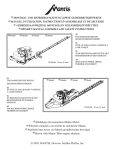
Download Mantis DOUBLE EDGED DEHT19 Owner`s manual
Transcript
®
OWNER’S MANUAL, ASSEMBLY
and SAFETY INSTRUCTIONS
for Gasoline Hedge Trimmer Attachment
Single Edge
Gasoline
Hedge Trimmer
Attachment
Shown with Mantis Tiller engine attached.
AND
Double Edge
Gasoline
Hedge Trimmer
Attachment
Shown with Mantis Tiller engine attached.
©2009, MANTIS, Division Schiller Grounds Care, Inc.
TABLE OF CONTENTS
I. IMPORTANT INFORMATION
II. SAFETY AND WARNINGS
A. Safety Decals.........................................4
B. Safety Decal Identification ...................4
C. General Safety Rules ............................5
D. Warnings — Don'ts ...............................5
E. Warnings — Do’s ...................................6
This professional trimming machine was
designed to the highest standards to ensure
you many hours of uninterrupted service.
A. INTRODUCTION
On behalf of everyone at Mantis we would
like to thank you for your purchase of a
Mantis Gasoline Powered Hedge Trimmer.
I. IMPORTANT INFORMATION
A. Introduction ..........................................2
B. Special Safety Information ...................2
C. Fuel Safety Information........................3
Page
This manual provides the information necessary
for safe and efficient operation and service.
For your safety, it is critically important that
you read and understand this entire manual
before operating your hedge trimmer.
III. ASSEMBLY INSTRUCTIONS ..........................7 - 8
IV. OPERATION ...................................................9
This manual contains different assembly
instructions for both the Single Edge Gasoline
Hedge Trimmers and the Double Edge
Gasoline Hedge Trimmers.
Be sure to follow the proper instructions for
your trimmer.
V.TRIMMING .....................................................10
VI. MAINTENANCE
A. Lubrication ..........................................10
B. Long Term Storage (over 60 days)......11
VII. SERVICE
A. Trouble Shooting ................................11
B. Service Maintenance Guide ...............11
C. Blade Adjustment ...............................12
VIII. PARTS EXPLOSIONS ...........................12 - 16
SERVICE
AND
WARRANTY POLICY.......................18
B. SPECIAL SAFETY INFORMATION
!
WARNING
DANGER
!
ATTENTION: THIS SYMBOL POINTS OUT OUR
IMPORTANT SAFETY INSTRUCTIONS.
WHEN YOU SEE THIS SYMBOL,
!
!
WARNING
HEED IT’S WARNING! STAY ALERT!!
DANGER
!
TO REDUCE THE POTENTIAL FOR ACCIDENTS,
COMPLY WITH THE SAFETY INSTRUCTIONS IN THIS MANUAL.
FAILURE TO COMPLY MAY RESULT IN
SERIOUS PERSONAL INJURY AND OR EQUIPMENT
AND PROPERTY DAMAGE.
2
C. Fuel Safety Information
! WARNING
DANGER !
HANDLE FUEL WITH CARE, IT IS HIGHLY FLAMMABLE. FUELING A HOT
ENGINE OR NEAR AN IGNITION SOURCE CAN CAUSE A FIRE AND
RESULT IN SERIOUS PERSONAL INJURY AND/ OR PROPERTY DAMAGE.
Don’t fuel, refuel or check fuel while smoking or
near an open flame or other ignition source. Stop
engine and be sure it is cool before refueling.
Always pull starter cord slowly until resistance is
felt. Then pull cord rapidly to avoid kickback and
prevent arm or hand injury.
Don’t leave the engine running while the trimmer
is unattended. Stop engine before putting the
trimmer down or while transporting from one
place to another.
Always operate engine with spark arrestor
installed and operating properly. The use of spark
arrestor mufflers is required by law in the state of
California (Section 4442 of the California Public
Resources Code), as well as in other states or
municipalities. Federal laws apply on
federal lands.
Don’t start, run or refuel this trimmer indoors, or
in an improperly ventilated area as poisonous carbon monoxide and other gasses are emitted.
Don’t run engine when electrical system causes
spark outside the cylinder. During periodical
checks of the spark plug, keep plug a safe distance
from cylinder to avoid burning of evaporated fuel
from cylinder.
Don’t check for spark with spark plug or plug wire
removed and grounded. Use an approved tester.
Sparks can ignite fumes.
Don’t crank engine with spark plug removed. If
the engine is flooded, open the choke (push choke
knob in) and pull recoil until engine starts. Follow
instructions in Tiller manual.
Don’t run engine when the odor of gasoline is present, or other explosive conditions exist.
Don’t operate the unit if gasoline is spilled. Clean
up spill completely before starting engine.
Don’t operate the unit if there is an accumulation
of debris around the muffler, and cooling fins.
Always handle fuel with care; it is highly flammable. Never add fuel to a machine with a
running or hot engine. Do not inhale fuel fumes as
they are toxic.
Always know how to stop machine quickly in an
emergency.
! Warning:
!
The Engine Exhaust from this product contains
chemicals known to the State of California to
cause cancer, birth defects or other reproductive
harm.
Don’t touch hot mufflers, cylinders or cooling fins
as contact may cause serious burns.
Don’t refuel indoors or in an improperly ventilated
area.
II. SAFETY AND WARNINGS
!
WARNING
DANGER
!
IF TRIMMER IS USED IMPROPERLY OR SAFETY PRECAUTIONS ARE NOT
FOLLOWED, THE USER RISKS SERIOUS INJURY TO THEMSELVES AND OTHERS.
READ AND UNDERSTAND THE FOLLOWING BEFORE ATTEMPTING TO OPERATE
THIS HEDGE TRIMMER.
3
! A. SAFETY DECALS
An important part of the safety system incorporated in this trimmer are the warning and informational decals found on various parts of the trimmer. These decals must be replaced in time
due to abrasion, etc. It is your responsibility to replace the decals when they become hard to
read. The part numbers for ordering decals are in Section B, Safety Decal Identification (shown
at bottom of this page). The location of these decals is illustrated below.
MANTIS LABEL
P/N 487 MA
Single Edge Gasoline
Hedge Trimmers
Double Edge Gasoline
Hedge Trimmers
MANTIS LABEL
P/N 487 MA
! B. SAFETY DECAL IDENTIFICATION
!
WARNING
!
P/N 300605
READ AND UNDERSTAND OPERATOR’S MANUAL BEFORE USING! KEEP IN A SAFE PLACE!
KEEP BOTH HANDS ON HANDLES AND AWAY FROM BLADES!
KEEP A SURE FOOTING AND NEVER OVERREACH! WHEN REACHING HIGH, STAND ONLY
ON A STABLE SUPPORT, AND NEVER ON THE TOP OF A LADDER!
BLADES COAST AFTER THROTTLE TRIGGER IS RELEASED OR ENGINE IS SWITCHED OFF!
NEVER OPERATE WITHOUT GUARDS, HANDLES, AND SAFETY DEVICES IN PLACE!
P/N 300605
Warning Label
P/N 4036
Ear and Eye Protection
(Located on your engine.)
Important Note: If Safety Decals are not found on your engine, they must be replaced. Call our
Customer Service department for information at 215-355-9700.
4
!
C. GENERAL SAFETY RULES
1. Read and understand the owner’s manual.
Pay particular attention to all sections
regarding safety.
5. Maintain a firm footing and good balance,
do not overreach while trimming. Before
you start to trim, check the work area for
obstacles that might cause you to lose
footing, balance, or control of the machine.
While operating the machine, always be
sure of a safe and secure operating position
especially when using steps or a ladder.
2. Always keep a firm grip on both handles
while the blades are moving and/or the
engine is running. The right hand grasps
the front handle on double edge hedge
trimmers or the side handle on the single
edge hedge trimmers. The left hand
grasps the rear handle.
BE AWARE!! The blades coast after
throttle trigger is released or engine is
switched off. Make sure blades have come
to a complete stop and the engine is off
before releasing a handle.
6. Blades coast after throttle trigger is released
or engine is switched off.
3. Keep area clear of children, pets, and
bystanders.
9. Never attempt to use an incomplete
machine or one fitted with an unauthorized
modification.
4. THIS MACHINE CAN CAUSE SERIOUS
INJURIES. Read instructions carefully for
the correct handling, preparation, mainenance, starting and stoping of the
machine. Be familiar with all controls and
the proper use of the machine. Pay particular attention to all sections regarding safety.
! WARNING
DANGER !
IF TRIMMER IS USED IMPROPERLY OR SAFETY
PRECAUTIONS ARE NOT FOLLOWED, THE USERS
RISK SERIOUS INJURY TO THEMSELVES
AND OTHERS.
READ AND UNDERSTAND THE FOLLOWING
BEFORE ATTEMPTING TO OPERATE
THIS HEDGE TRIMMER.
! D.
WARNINGS — DON’TS
Don’t use trimmer with one hand; keep both
hands on handles with fingers and thumbs
encircling the handles, while blades are moving and engine is running.
Don’t overreach or stand on unstable support.
Do not stand on the top of a ladder while trimming. Use proper equipment for reaching
higher heights. Keep a good footing at all
times.
Don’t ever grasp cutting blades for any reason.
Don’t attempt to clear cut material while
blades are moving, and the engine is running.
Never try to remove jammed material before
7. Stop engine before checking, maintenance
or working on the machine.
8. Never operate without guards, handles and
safety devices in place.
10. To reduce fire hazard, keep engine and
silencer free of debris, leaves, or excessive
lubricant.
11. Know how to stop this machine in an
emergency.
! WARNING
DANGER
!
THE BLADES COAST AFTER THROTTLE
TRIGGER IS RELEASED OR ENGINE IS
SWITCHED OFF. MAKE SURE BLADES
HAVE COME TO A COMPLETE STOP
AND ENGINE IS OFF BEFORE
RELEASING A HANDLE
switching the engine off and making sure the
blades have stopped completely.
Don’t override safety features.
Don’t allow children or incapable people to
operate this trimmer.
Don’t operate this hedge trimmer while under
the influence of alcohol or drugs.
Don’t attempt to repair this hedge trimmer.
Have repairs made by a qualified dealer or
repairman. See that only original Mantis
parts are used.
Don’t operate the machine with a damaged or
excessively worn cutting device.
5
!
E. WARNINGS — DO’S
Always read and follow all instructions.
Always stay alert. Watch what you are doing
and use common sense. Do not operate unit
when fatigued.
Always dress properly. Do not wear loose
clothing or jewelry, they might get caught in
moving parts. Use sturdy proper fitting, nonslip gloves. Gloves reduce the transmission of
vibration to your hands. Prolonged exposure to
vibration can cause numbness and other ailments. Wear non-skid footwear to ensure
secure and proper footing.
Always wear ear and eye protection. Eye protection must meet ANSI Z 87.1. To avoid
hearing damage we recommend hearing protection be worn whenever using the equipment.
Always keep both hands on both handles
when trimmer is running. Severe injuries can
result if you try to use the hedge trimmer with
only one hand or with an insecure grip.
Always keep children, pets, and incapable persons away.
Always use trimmer properly. Cut only types
and size of growth described in the Trimming
section of this manual. Overloading or abusing your hedge trimmer can cause premature
failure and can result in injury. Use common
sense.
Always keep a safe distance between two or
more operators when working together
simultaneously.
Always inspect your unit before each use and
ensure that all handles, guards, safety devices
and fasteners are secure, operating, and in
place.
Always maintain and examine your trimmer
with care. Follow maintenance instructions
given in manual.
Always store trimmer in a sheltered area (a dry
place) not accessible to children. The hedge
trimmer as well as fuel should not be stored in
a house.
Always be aware of power lines.
Always stop the engine before adjusting the
working position of the cutting device.
Always make sure that the cutting blades are
in the correct working position that you want
before starting the engine.
Important: Always follow the Engine and Fuel Warnings found in
your Tiller Manual.
If you don’t have your Tiller Manual, call our Customer Service
Department at 1-800-366-6268 to purchase a replacement or visit
www.mantis.com to download a copy.
6
III. ASSEMBLY INSTRUCTIONS
! WARNING
DANGER !
BLADES ARE EXTREMELY SHARP. TO AVOID
INJURY WHEN UNPACKING AND ASSEMBLING
THE HEDGE TRIMMER, DO NOT GRASP
THE BLADES.
A. DOUBLE EDGE GASOLINE HEDGE
TRIMMERS (CAT # 2224DAHM)
NO HEDGE TRIMMER ATTACHMENT ASSEMBLY
IS NEEDED.
To attach your engine, see sections
B 3, 4, 5, 6, 7, 8.
1. Remove the cutter bar assembly,
throttle assembly with side handle, and hardware bag from their boxes.
The hardware bag consists of the following
items:
P/N
Description
Qty
1/4-20 Lock Nut
Handle Support Channel
Spacer Tube
Shock Absorber
Support Plate
1/4-20 x 2 1/2 Bolt
1/4-28 Flange Locknut
! WARNING
DANGER !
IMPROPER ASSEMBLY OF THIS
TRIMMER CAN RESULT IN
SERIOUS INJURY.
MAKE SURE TO FOLLOW ALL
INSTRUCTIONS CAREFULLY.
B. SINGLE EDGE GASOLINE
HEDGE TRIMMERS (CAT # 2230SAM)
972
300102
300113
300111
300112
300505
3036-B
the handle in the most comfortable position
for you. Place the thread protectors over the
set of studs that you choose not to use at this
time to protect the threads. Secure the handle
in place using two 1/4-28 flange locking nuts
provided. The nuts should be tightened
enough to keep the handle from moving but
not so tight as to crush the plastic.
2
2
2
4
1
2
2
IF YOU HAVE ANY QUESTIONS CALL
1-800-366-6268 AND ASK FOR SERVICE
OR FOR THE NAME OF YOUR LOCAL
MANTIS DEALER.
3. To remove the engine from your Mantis
tiller you will need to identify which throttle
cable connection you have. There are two different styles.
To remove the engine if your tiller has the
connection shown in picture 1, (SV4 Engine
models only). First remove the air cleaner
cover and air filter.
If your tiller has an engine that looks like in
picture 2, just follow the written instructions.
2. Place the front side handle over the two
1/4-28 studs protruding from the frame bar in
front of the gear housing. The handle grip
must be pointing away from the cutting
blades as illustrated below. On Model
2230SAH use the set of studs which places
7
Detach the throttle cable at the carburetor by
loosening the two 10mm nuts on the threaded end
Throttle Cable
10mm nuts
Swivel
engine. Slide the engine over the 1” diameter
stem containing the hex drive on the gear
housing until it is seated all the way down on
the gear housing (see illustration below).
6. Press shock absorbers into sockets on the
gear housing followed by the spacer tubes.
Secure handle and tubing support channels
with the 1/4-20 hex bolts and locking nuts
supplied. (See illustration at the top right)
Slide the cable out and down to unhook it
from the swivel. Separate the ground wire at
the wire connection, which is approximately
3" from the engine.
Loosen the screw at the very bottom of the
engine, just above where the handles are
attached to the tiller. Then just lift the
engine up.
ATTACHING THE ENGINE TO EITHER THE SINGLE
EDGE OR DOUBLE EDGE TRIMMER ATTACHMENT
4. First, fasten the black ground wire from the
handle assembly to the ground screw. Use
the screw that is located on the bottom of the
engine, closest and to the right of the fuel tank.
This ground wire has an eyelet connection.
Therefore, when you want to remove the
engine from the trimmer, just separate the
wire connection. It is not necessary to
unscrew the ground screw. See illustration.
5. Install the engine to the hedge trimmer
8
by first aligning the hex drive on the trimmer
gear housing with the hex socket in the
7. Plug the red wire from the engine into the
switch wire (rectangular flat connector) from
the handle assembly.
8. Feed the throttle cable up between the fuel
tank and the carburetor. Locate the metal
“button” on the triangle. This is the swivel.
The large end of the throttle cable must be
inside the slot in this swivel. (See Picture 3.)
Separate the two nuts and washers and slide
them onto the engine. (See Picture 2.) Adjust
the nuts so the triangle touches the carburetor
case when you squeeze the trigger and hits the
idle screw when the trigger is released. (Picture
2.) Tighten the two nuts until they are snug
using a 10mm or an adjustable wrench.
Throttle movement should be smooth and
unobstructed. Align the engine and tighten the
mounting screw. Reinstall the filter and filter
cover.
IV OPERATION
! WARNING
DANGER !
THE OPERATOR OF THIS HEDGE TRIMMER IS RESPONSIBLE FOR
ACCIDENTS OR HAZARDS OCCURRING TO HIMSELF,
OTHER PEOPLE OR THEIR PROPERTY.
CHECK YOUR TILLER MANUAL
FOR PROPER OPERATING INSTRUCTIONS FOR THE ENGINE
STARTING THE ENGINE WITH THE TRIMMER
STOPPING THE ENGINE WITH THE TRIMMER
2. Slide the ignition switch to the START
position.
2. Slide ignition switch to the STOP
position.
3. Proceed with engine starting
instructions found in your Tiller Manual.
3. Make sure blades have come to a complete stop before releasing either handle.
ATTACHMENT
1. Release the throttle trigger and allow
engine to idle.
ATTACHMENT
1. Place the hedge trimmer flat on the
ground, or other stable surface.
Single edge hedge
trimmer attachments
Double edge hedge
trimmer attachments
! WARNING
! WARNING
DANGER
!
AVOID ACCIDENTAL BLADE
ENGAGEMENT.
DO NOT SQUEEZE THE THROTTLE
TRIGGER WHEN STARTING.
MAINTAIN PROPER IDLE SPEED
ADJUSTMENT (2200-2300 RPM)
DANGER !
IF ENGINE DOES NOT STOP WHEN
SWITCH IS PUT IN THE STOP
POSITION, RELEASE THE THROTTLE
TRIGGER, ALLOW ENGINE TO IDLE.
PUT THE TRIMMER DOWN, AND
PULL THE CHOKE BUTTON OUT TO
COLD START (CLOSED) POSITION.
CHECK AND REPLACE
IGNITION SWITCH BEFORE
STARTING ENGINE AGAIN.
9
V. TRIMMING
! WARNING
proceed to cut. Use overlapping sweeping
motions away from your body to achieve a
safe and even cut.
DANGER
!
BLADES COAST AFTER RELEASING
THROTTLE OR STOPPING ENGINE.
KEEP A FIRM GRIP WITH BOTH
HANDS ON BOTH HANDLES WHILE
BLADES ARE MOVING AND/OR
ENGINE IS RUNNING.
DO NOT STAND ON THE TOP OF A
LADDER WHILE TRIMMING.
MAKE SURE YOUR LADDER OR
OTHER SUPPORT IS STABLE AND ON
FIRM GROUND.
KEEP A SURE FOOTING.
DO NOT OVERREACH.
IF YOUR TRIMMER BECOMES
JAMMED RELEASE THROTTLE AND
STOP ENGINE. MAKE SURE B LADES
HAV E STOPPED COMPLETELY.
REMOVE THE SPARK PLUG CAP FROM
THE SPARK PLUG, THEM REMOVE
THE OBSTRUCTION.
1. WARNING! Read and follow all safety
instructions in the manual before attempting to
use this trimmer.
2. Only after you are familiar with your
hedge trimmer and all of its controls and the
functions should you start the engine.
3. Once the engine is started grasp the handles securely, the left hand should grasp the
rear handle.The right hand should grasp the
front (on the double edge hedge trimmer) or
side (on the single edge hedge trimmer) handle.
4. Squeeze the throttle to accelerate the
engine and engage the blades.
10
5. Tilt the trimmer so the cutting teeth are
angled slightly toward the hedge or shrub and
6. These units are designed to
cut any type of hedge or
shrub; however,
THICKNESS OF
CUT SHOULD
NOT EXCEED
1 INCH IN DIAMETER.
1"
Misuse of this Hedge Trimmer will void the
warranty.
ie: Cutting hedges or shrubs over 1" in diameter or foreign objects such as wires, rocks, or
fences. Before trimming, check work area for
foreign objects such as wires, cords, glass,
fences, or rocks. Be sure to remove any
foreign object from work area. Failure to
properly maintain this hedge trimmer will
void the warranty.
VI. MAINTENANCE
A. LUBRICATION
1. A few drops of a light #10 oil should be
placed on the back edge of each blade guard, or
protective comb, at each adjusting screw
approximately after every 4 hours of normal
operation.
2. To obtain trouble free trimming, it is
necessary to keep the blades lubricated and
clean. The gum that collects and builds up on
the blades can be removed with a 50-50
mixture of kerosene and #10 oil. As petroleum
products can shorten the life of some plastics
it is necessary to remove excess oil-kerosene
mixture from the plastic parts.
3. When blades are replaced, or any other
time that the bottom cover plate is removed,
the grease level should be checked for proper
amount (approximately 3/4 full in the area of
the gears) and a new gasket should be used to
insure proper seating of the cover plate. Use
only Lubrico M3-3K-9K grease in the gear
housing.
FOR ENGINE MAINTENANCE, SEE YOUR
MANTIS TILLER MANUAL. IF YOU DON’T HAVE YOUR
TILLER MANUAL, CALL OUR CUSTOMER SERVICE
DEPARTMENT AT 800-366-6268 TO PURCHASE A
REPLACEMENT. OR VISIT WWW.MANTIS.COM TO
coat the blades with oil to prevent rust.
4. Perform all required maintenance and
service found in this manual.
DOWNLOAD A COPY OF THIS MANUAL
5. Drain the fuel tank and pull the starter
rope several times to remove the fuel from
the carburetor.
B. LONG TERM STORAGE (OVER 60 DAYS)
1. Store your trimmer in a dry and dust free
space, out of the reach of children.
!
WARNING
DANGER
6. Remove the spark plug and pour 1/4 oz. of
fresh, clean, two-stroke engine oil into the
cylinder via the spark plug hole. Cover the
hole with a rag and pull the starter rope 2-3
times.
!
DO NOT STORE IN AN AREA WHERE
FUEL FUMES MAY
ACCUMULATE AND REACH A FLAME
OR SPARK.
7. While looking through the spark plug hole
pull the starter rope until the piston reaches
the top of it’s stroke and stop.
2. Place the ignition switch in the stop
position.
8. Install the spark plug, but leave the ignition cable disconnected.
3. Clean the engine and blades thoroughly and
VII. SERVICE
A. TROUBLE SHOOTING
Problem
Cause
Remedy
1. Blades don’t cut cleanly.
Blades are dull or not adjusted
properly.
Have blades sharpened and
adjusted.
2. Blades don’t move when
throttle is squeezed.
Engine is not seated properly
on the gear housing.
Blades are adjusted too tightly.
Re-install engine following the
assembly instructions.
Re-adjust blades following
service instructions.
See your Tiller Manual for Engine Trouble Shooting
B. SERVICE MAINTENANCE GUIDE
Area
Gear Housing
Blades
Fasteners
Labels
Handles
Guards / Safety Devices
Maintenance
Check Grease
Inspect / Clean / Lubricate
Inspect / Tighten / Replace
Inspect / Replace
Inspect / Replace
Inspect / Replace
Frequency
Monthly
After Use
Before Use
Before Use
Before Use
Before Use
IMPORTANT- Time Intervals shown are maximum. Actual use and your experience will
determine the frequency of required maintenance.
11
C. BLADE ADJUSTMENT
!
WARNING
Single Edge Trimmer
DANGER
!
SWITCH OFF THE ENGINE BEFORE
LUBRICATING OR ADJUSTING THE
BLADES
The care and adjustment of the blades is most
important to the efficient operation of the
trimmer and especially to the long life of the
engine.
1. Place the trimmer in vise clamping on the
frame bar. Be careful! Blades are sharp!
2. Using a 7/16” wrench, loosen all blade
locknuts and unscrew the large head screws
by two turns.
3. Starting with the screw nearest the gear
housing, tighten the screw until the blade
guard of the Single Edge trimmer or the protective comb of the Double Edge trimmer can
just be moved with finger pressure and a
.0015” (1 1/2 thou.) feeler blade just slips
under the blade guard or comb. Tighten the
locknuts while holding the screw stationary in
its correctly adjusted position.
4. Repeat Step 3 on the screws in turn until
all are correctly adjusted.
NOTE: CORRECT
BLADE ADJUSTMENT CAN ONLY BE
ACHIEVED ON CLEAN, OILED BLADES.
VIII. PARTS EXPLOSIONS
GEAR HOUSING ASSEMBLY
Key
No.
12
1
2
3
4
5
6
7
8
9
10
11
12
13
Part No.
371
375
374
300000
D16-56F
16-61
372
314
319
316
16-81
16-80
373
Description
Qty.
Pinion
1
Washer
1
Upper Bushing
1
Gear Hsg Assem. (inc. Key No. 3, 6, 12) 1
Wear Plate
1
Eccentric Shaft
1
Eccentric Gear
1
Felt
1
Gasket
1
Cover Plate
1
6-32 x 5/16 Screw Pack
1
Cover Plate Pin
1
Lower Bushing
1
Double Edge Trimmer
Key
No.
1
2
3
4
5
6
7
Part No.
300000
16-54B
300300
300200
300201
300310
30-2
Description
Gear Housing Assembly
1/4-28 Whiz Flange Locknut
Frame Bar Brace
Side Handle
Grip
30" Frame Bar
30" Inside Blade
Qty.
1
7
1
1
1
1
1
Key
No.
8
9
10
11
12
13
14
15
Part No.
30-1
16-93
16-54A
300504
16-65
16-64
300316
3036-B
Description
30" Outside Blade
Blade Guard
Large Head Phillips Screw
Large Head Screw 1/4-28 x 7/8
Connecting Rod Spacer
Connecting Rod
Thread Protector
1/4-28 Flange Locknut
Qty.
1
5
4
1
1
1
2
2
CUTTING BAR AND SIDE HANDLE ASSEMBLY
Single Edge Trimmers
13
Key
No.
1
2
3
4
5
6
7
8
9
11
12
13
Part No.
300101
300103
300117
300122
300108
---300120
973
300116
300503
972
300102
Description
Handle
Grip (Set)
Switch Plate
Trigger Set
Trigger \ Lockout Springs
-----Switch/With Leads
10-32 Lock Nut
Conduit
10-32 x 1 1/4" Machine Screw
1/4-20 Lock Nut
Handle Support Channel
Qty.
1
1
1
1
1
1
1
1
1
2
2
Key
No.
14
15
16
17
18
19
20
21
22
23
24
25
26
Part No.
300113
300111
300112
300505
300502
300500
300115
300000
300511
300109
300118
376-1
300121
Description
Spacer
Shock Absorber
Support Plate
1/4-20 x 2 1/2" Bolt
6MM Star Lock Washer
6MM Nut
Throttle Cable
Gear Housing Assembly
7/8" Phillips Pan Head Screw
Switch Cap
Cable Tie
Handle End Cap
Eyelet Spade Terminal
Qty.
2
4
1
2
2
2
1
1
4
1
1
1
1
REAR HANDLE ASSEMBLY
Single Edge Trimmers
14
Key
No.
2
3
4
5
6
7
7
8
8
9
9
Part No.
300115
300500
300502
300119
16-54B
300308
300312
24-2D
30-2D
24-1D
30-1D
Description
Throttle Cable
6MM Nut
6MM External Star Lockwasher
Conduit
1/4 - 28 Whiz Flange Locknut
24" D.E. Frame Bar w/Studs (for model 2224DAH)
30" D.E. Frame Bar w/Studs
24" D.E. Inside Blade
30" D.E Inside Blade
24" D.E. Outside Blade
30" D.E. Outside Blade
Qty.
1
2
2
1
7
1
1
1
1
1
1
Key
No.
10
11
12
13
14
15
16
17
18
19
20
21
Part No.
24-42
16-54A
300504
16-65
16-64
300512
300112
300403
300000
300113
972
300300
Description
24" Protective Comb
Large Head Phillips Screw
7/8" Large Head Phillips Screw
Connecting Rod Spacer
Connecting Rod
1/4 - 20 x 2 1/4 Bolt
Support Plate
Shock Absorber
Gear Housing Assembly
Spacer Tube
1/4 - 20 Locknut
Frame Bar Brace
Qty.
1
3
1
1
1
2
3
8
1
4
2
1
CUTTING BAR ASSEMBLY
Double Edge Trimmers
15
Key
No.
1
2
3
4
5
6
7
8
9
Part No.
300511
300113
300403
328
300506
300510
300508
300400
300507
Description
7/8" Phillips Pan Head Screw
Spacer Tube
Shock Absorber
1/4" Flat Washer
1/4-28 x 1 5/8 Hex Head Bolt
10-32 x 4 Hex Head Bolt
#10 Flat Washer
Grip Set
10-32 x 5 1/2 Hex Head Bolt
Qty.
8
4
8
2
2
1
2
1
1
Key
No.
10
11
12
13
14
15
16
17
18
19
Part No.
300405
300404
300120
300117
300122
300108
----300109
973
300121
Description
Hand Guard
Front Handle
Switch With Leads
Switch Plate
Trigger Set
Trigger/Lockout Spring
-------Switch Cap
10-32 Locknut
Eyelet Spade Terminal
Qty.
1
1
1
1
1
1
1
2
1
HANDLE ASSEMBLY
Double Edge Trimmers
16
Return Information
If you are having any trouble with any
Mantis product, please call us. Ask for
Customer Service. Usually, we can
solve most problems over the phone.
If we are unable to solve your problem
and you still want to return the attachment...
Always call first —
1-800-366-6268
to receive your Return Authorization
number.
Please have the following information
when you call:
IF YOU NEED TO
RETURN A PRODUCT
Very few customers ever need to return
a Mantis product, but just in case you
have to...here are some simple instructions that will help us serve you quicker
and better.
Please clean the product if it has been
used. (Remove dirt from attachment).
Give us as much information as possible, so that we can help you as quickly
as possible.
1. Date of purchase
2. Date attachment was first used
3. Customer number, if available
Please provide the following information and send this completed form with your product.
Name
Phone: Day (
)
Address
Evening (
)
City State Zip
Customer No:
(not necessary but helpful)
Product(s) being returned
What do you want us to do?
Repair
Refund
Other
If you are requesting a refund, please tell us why:
Product is different than I expected
Not satisfied with performance
Not satisfied with quality
Other
For repair service, please continue on other side of this form.
17
ATTACHMENT LIMITED SERVICE & WARRANTY POLICY
The Mantis Tiller and its attachments are guaranteed against defects in material and workmanship for a
period of TWO YEARS FROM DATE OF PURCHASE. All tines for the tiller are guaranteed for life against
breakage. Any Mantis products or parts found to be defective within the warranty period are to be returned to
our factory at Southampton, PA
Transportation charges on parts and units submitted for repair or replacement under this warranty must be
paid by the purchaser.
THIS WARRANTY shall not be effective if the product has been the subject of misuse, negligence or accident
or if the product has been repaired or altered outside of our Southampton factory in any respect which
affects its condition or operation.
Mantis shall not be liable for any special indirect or consequential damages arising from defective equipment.
Any implied warranty, including merchantability or fitness for a particular purpose, shall not extend
beyond the written warranty period.
®
1028 Street Road • Southampton, PA 18966
(215) 355-9700 • 1-800-366-6268
! Warning: The Engine Exhaust from this product contains chemicals known to the
State of California to cause cancer, birth defects or other reproductive harm.
For additional information on the care and use of any Mantis attachment, please call our Service Department at 800-366-6268
If you are returning a product for repair or for a repair cost estimate, please tell us
what appears to be broken or what performance needs to be improved:
Disassemble and pack your product in the original shipping
carton or any other strong corrugated box. Ship the returned
product, prepaid, by UPS or USPS (Post Office).
When shipping through the Post Office, be sure to insure your product
for replacement value and ship certified.
FOR REPAIR or REFUNDS:
MANTI S
1028 Street Road
Southampton, PA 18966
©Schiller Grounds Care, Inc, 2009
P/N 300703 08-09


