
1
Preface
1
Introduction
2
Network Topologies
3
Product Characteristics
4
Installation and Maintenance
5
Approvals and Marks
6
References
7
61H
62H
SIMATIC NET PROFIBUS
Optical Link Module
OLM / P11 V4.0
OLM / P12 V4.0
OLM / P11 V4.0
OLM / G12 V4.0
OLM / G12-EEC V4.0
OLM / G11-1300 V4.0
OLM / G12-1300 V4.0
Operation manual
01/2007
A2B00065774D, Edition V1.0
63H
65H
64H
Safety Guidelines
This operation manual contains notices which you should observe to ensure your own personal safety as well as
to avoid property damage. The notices referring to your personal safety are highlighted in the manual by a safety
alert symbol, notices referring to property damage only have no safety alert symbol. Depending on the danger
level, the notices are displayed in descending order as follows.
Danger
indicates that death or severe personal injury will result if proper precautions are not taken.
Warning
indicates that death or severe personal injury may result if proper precautions are not taken.
Caution
with safety alert symbol indicates that minor personal injury can result if proper precautions are not taken.
Caution
without safety alert symbol indicates that property damage can result if proper precautions are not taken.
Notice
used without the safety alert symbol indicates a potential situation which, if not avoided, may result in an
undesirable result or state.
When several danger levels apply, the notices of the highest level (lower number) are always displayed. If a
notice refers to personal damages with the safety alert symbol, then another notice may be added warning of
property damage.
Copyright Siemens AG 2007. All rights reserved.
Disclaimer
Siemens AG
Automation and Drives
Postfach 4848, D-90327 Nürnberg
Siemens AG 2007
Subject to technical modifications
Siemens Aktiengesellschaft
A2B00065774D, Edition V1.0
Passing on and copying this document, validation and edition of its content is not
permitted, if not especially allowed. Infringements oblige to amends. All rights reserved,
especially in the case of patent chartering or GM entry.
We checked the content of this print on compliance with the described hardware and
software. Nevertheless variations can not be excluded, so that we do not take liability for
complete compliance. The information in this print is checked regularly, necessary
corrections are enclosed in the subsequent editions.
Qualified Personnel
The device/system may only be set up and operated in conjunction with this documentation. Only qualified
personnel should be allowed to install and work on the equipment. Only qualified personnel should be allowed
to install and work on the equipment. Qualified personnel in the sense of the safety related notices of this
documentation are persons who have the right to commission, ground and label devices, systems and electric
circuits in accordance with the standards of the safety technology.
Intended use
Please observe to the following:
Warning
The device may only be used for the purposes designated in the catalog and in the technical description and may
only be used in connection with third party devices and components recommended or approved by Siemens. The
proper and safe operation of the product implies appropriate transportation, appropriate storing, positioning and
assembly as well as accurate operation and maintenance.
Note: If the PROFIBUS OLM are supplied via extensive 24V supply lines or networks, actions against the
injection of strong electro magnetic pulses into the supply lines have to be taken. These can occur for example
by lightning strike or switching of heavy inductive loads. The robustness of the PROFIBUS OLM against
electromagnetic interference is amongst others verified by the Surge Immunity Test according to
EN61000-4-5. For this test, an over voltage protection for the voltage supply lines is necessary. For example
the Dehn Blitzductor VT AD 24V Art. No. 918402 or an equal protection element are suitable. Manufacturer:
DEHN+SÖHNE GmbH+Co.KG Hans Dehn Str.1 Postfach 1640 D-92306 Neumarkt, Germany
Brands
All names which are labeled with the trademark ® are incorporated brands of the Siemens AG. All other names
in this script can be brands, whose use by third parties for their purposes can violate the rights of the owner.
SIMATIC NET PROFIBUS, Optical Link Module
Operation manual, 01/2007, A2B00065774D, Edition V1.0
iii
Table of Contents
1
Preface ...................................................................................................................................................... 1
0H
6H
1.1
1H
2
Preface ........................................................................................................................................... 1
67H
Introduction................................................................................................................................................ 3
2H
68H
2.1
3H
3
Introduction .................................................................................................................................... 3
69H
Network Topologies ................................................................................................................................... 7
4H
70H
3.1
Bus Topology ................................................................................................................................. 8
3.1.1
Bus topology with fiber optic cable distance monitoring and segmentation .................................. 9
3.1.2
Bus topologies without fiber optic cable distance monitoring ........................................................ 9
3.2
Sterntopologie ..............................................................................................................................10
3.3
Ring topology ...............................................................................................................................12
3.3.1
Redundant optical Ring with two OLMs ....................................................................................... 14
5H
6H
7H
8H
9H
10H
4
71H
72H
73H
74H
75H
76H
Product Characteristics............................................................................................................................ 17
1H
7H
4.1
Technical data ..............................................................................................................................17
4.2
Installation ....................................................................................................................................20
4.2.1
Safety related notices ..................................................................................................................20
4.2.2
General information on the commissioning .................................................................................21
4.2.3
Setting of compatibility, operation mode and transmission rate .................................................. 22
12H
13H
14H
15H
16H
5
78H
79H
80H
81H
82H
Installation and Maintenance ................................................................................................................... 27
17H
83H
5.1
Installation ....................................................................................................................................27
5.1.1
Installation instructions.................................................................................................................27
5.1.2
Connection of the optical lines .....................................................................................................30
5.2
Installation of the modules ...........................................................................................................31
5.3
Connection of the electrical RS 485 bus lines .............................................................................32
5.4
Connection of the operation voltage supply.................................................................................34
5.5
Connection of the signaling contact lines ....................................................................................34
5.6
Receiving level of the optical channels ........................................................................................35
5.7
LED displays and error search.....................................................................................................36
5.7.1
LED displays ................................................................................................................................36
5.7.2
Error search .................................................................................................................................38
5.8
Maintenance.................................................................................................................................40
5.9
Cleaning .......................................................................................................................................40
5.10
Configuration ................................................................................................................................41
5.10.1
Configuration of optical bus and star topologies ..........................................................................41
5.10.2
Configuration of redundant optical rings ......................................................................................41
18H
19H
20H
21H
2H
23H
24H
25H
26H
27H
28H
29H
30H
31H
32H
3H
6
84H
85H
86H
87H
8H
89H
90H
91H
92H
93H
94H
95H
96H
97H
98H
9H
Approvals and Marks ............................................................................................................................... 43
34H
10H
6.1
CE-mark .......................................................................................................................................43
6.2
c-tick .............................................................................................................................................44
6.3
FM approval .................................................................................................................................45
35H
36H
37H
10H
102H
103H
SIMATIC NET PROFIBUS, Optical Link Module
iv
Operation manual, 01/2007, A2B00065774D, Edition V1.0
6.4
Ex approval ..................................................................................................................................45
6.5
UL/CSA approval .........................................................................................................................45
38H
39H
7
104H
105H
References .............................................................................................................................................. 47
40H
106H
7.1
41H
References...................................................................................................................................47
SIMATIC NET PROFIBUS, Optical Link Module
Betriebsanleitung, 01/2007, A2B00065774D, Edition V1.0
107H
v
Tables
Table 2-1
Number of electrical and optical ports per module, .......................................................................4
Table 4-1
Overview of the product characteristics.......................................................................................19
Table 4-2
DIL-switch in compatibility mode..................................................................................................23
Table 5-1
Meaning of the LED displays and signalization via the signaling contact ...................................38
Table 5-2
Constant for the calculation of the slot time at DP-standard (redundant optical ring) .................42
Table 5-3
Constant for the calculation of the slot time at DP/FMS (”universal“) and DP with S5 95U
(redundant optical ring) ................................................................................................................42
108H
109H
10H
1H
12H
13H
Figures
Figure 2-1
PROFIBUS OLM with position of all interfaces, displays and adjustment possibilities .................3
Figure 3-1
Network structure in optical bus topology ......................................................................................8
Figure 3-2
Network structure in optical star topology....................................................................................10
Figure 3-3
Network structure in redundant optical ring topology ..................................................................12
Figure 4-1
View module OLM from top .........................................................................................................21
Figure 5-1
Actions against faults ...................................................................................................................27
Figure 5-2
Fixing of shielded lines with cable clamps and cable retainers ..................................................28
42H
43H
4H
45H
46H
47H
48H
14H
15H
16H
17H
18H
19H
120H
Figure 5-5
View of the module bottom ..........................................................................................................30
Installation of a module on a standard rail ...................................................................................31
Installation of a module with a mounting plate .............................................................................32
Figure 5-6
Electrical port, Connection assignment Sub-D jack...................................................................32
Figure 5-7
operation voltage supply, pin assignment 5 pin terminal block ...............................................34
Figure 5-8
Signaling contact relais with floating contacts; ...........................................................................34
Figure 5-9
Signaling contact, pin assignment 5 pin terminal block .............................................................34
Figure 5-10
Position of the level recording connections ................................................................................35
Figure 5-11
Assignment recorded output voltage to signal quality .................................................................35
Figure 5-12
LED displays at the front plate .....................................................................................................36
Figure 5-3
49H
Figure 5-4
50H
51H
52H
53H
54H
5H
56H
57H
58H
vi
12H
12H
123H
124H
125H
126H
127H
128H
129H
130H
SIMATIC NET PROFIBUS, Optical Link Module
Operation manual, 01/2007, A2B00065774D, Edition V1.0
1
1
Preface
1.1 Preface
Purpose of the operation manual
This operation manual supports you when commissioning PROFIBUS-OLM devices (Optical
Link Module)
Area of validity of this operation manual
This operation manual is valid for the following devices:
SIMATIC NET OLM/P11 V4.0
6GK1 503-2CA00
SIMATIC NET OLM/P12 V4.0
6GK1 503-3CA00
SIMATIC NET OLM/G11 V4.0
6GK1 503-2CB00
SIMATIC NET OLM/G12 V4.0
6GK1 503-3CB00
SIMATIC NET OLM/G12-EEC V4.0
6GK1 503-3CD00
SIMATIC NET OLM/G11-1300 V4.0
6GK1 503-2CC00
SIMATIC NET OLM/G12-1300 V4.0
6GK1 503-3CC00
Glossary
OLM/
G 1 2 -1300
optional: wavelength
Number of optical interfaces
Number of RS-485 interfaces
G glass fiber
P plastic fiber
SIMATIC NET PROFIBUS, Optical Link Module
Operation manual, 01/2007, A2B00065774D, Edition V1.0
1
Preface
1.1 Preface
Further Documentation
You can find additional tips on other SIMATIC NET products, which you can use with the
OLM V4.0 devices, in the manual “SIMATIC NET PROFIBUS networks SIEMENS AG”.
Finding information
To help you find the information you require more quickly, the manual includes not only the
table of contents but also the following sections in the Appendix:
Glossary
•
•
59H
Index
60H
Audience
This operation manual addresses persons involved in the commissioning of PROFIBUS
networks with the link modules of the OLM V4.0 series.
Standards and Approvals
The devices of the OLM V4.0 series meet the requirements for the CE mark. For detailed
information please refer to chapter 6 of this operation manual.
Additionally the devices of the OLM V4.0 meet the requirements for the UL, C-Tick, FM and
ATEX marks. For detailed information please refer to chapter 6 of this operation manual.
2
SIMATIC NET PROFIBUS, Optical Link Module
Operation manual, 01/2007, A2B00065774D, Edition V1.0
2
2
Introduction
2.1 Introduction
This chapter gives an overview on the functions of the PROFIBUS OLM4.0 product
family.
What Is Possible?
PROFIBUS OLMs are designed for the use in optical PROFIBUS field bus networks.
They allow the conversion of electrical PROFIBUS interfaces (RS 485 level) into optical
PROFIBUS interfaces and vice versa.
The modules can be integrated into existing PROFIBUS field bus networks – under
utilization of the known advantages of the optical transmission technology. A complete set
up of a PROFIBUS field bus network with modules in line, star or ring topology as well as
any combination of these topologies is possible, as well.
To increase the protection of the field bus network against failure, the redundant ring is
supported.
DIL switch for
operation modes
LED displays
Operating voltage
Signaling Contact
Recording jacks for
level recording of the
optical interfaces
(see chapter 5.6).
Channel 1
RS-485
Channel 2 Channel 3
Optical channels
Figure 2-1
PROFIBUS OLM with position of all interfaces, displays and adjustment possibilities
SIMATIC NET PROFIBUS, Optical Link Module
Operation manual, 01/2007, A2B00065774D, Edition V1.0
3
Introduction
2.1 Introduction
Every module has two (OLM P11, G11) or three (OLM P12, G12) independent channels
(ports), which consist of a transmission and a receiving unit.
The operation voltage supply is realized with 24 V DC voltage. To increase the operation
safety a redundant feed is possible.
The electric channel is designed as 9-pin sub-D socket (female). A RS 485 bus segment
according to PROFIBUS standard EN 50170 /2/ can be connected to this channel.
The fibre optic cables are connected via BFOC 1/2,5 connectors.
Six multicolor LEDs show the current operation mode and possible operation failures as
well as the level ratios on the optical interfaces.
0F
Table 2-1 shows the different connection options of the modules and the maximum
possible optical range of the single channels.
OLM/
P11
P12
G11
G12
G11-1300
G12-1300
G12-EEC
Number of channels
-electrical
1
1
1
1
1
1
-optical
1
2
1
2
1
2
80 m
80 m
-
-
-
-
400 m
400 m
-
-
-
-
- silica glass fiber optic cables
-
-
-
-
15 km
15 km
10/125 µm (9/125µm)
-
-
3 km
3 km
10 km
10 km
50/125 µm
-
-
3 km
3 km
10 km
10 km
Fiber types that can be used
- plastic fiber optic cables
980/1000 µm
- PCF fiber optic cables
(HCS®)
200/230 µm
62.5/125 µm
Table 2-1
Number of electrical and optical ports per module,
usable fiber types, as well as maximum achievable fiber optic cable distances between the modules.
See the “Technical Data” for exact frame conditions. PCF stands for Polymer Cladded Fiber and is
similar to HCS® 2.
1F
There is a measurement output for every channel, at which the optical input level can be
detected with a standard volt meter.
Different failure reports of the OLM are supplied as accumulative signal via a signaling
contact (relais with floating contacts) for further processing. The single operation modes
as well as failure notices are displayed through several multicolor LEDs at the front of the
device (see chapter 5.7.1).
The mechanical design consists of a compact and stable metal housing which can be
mounted either on a rail or on a mounting plate.
The configuration of the modules is realized via switches which are easy accessible from
the outside.
1
BFOC stands for Bajonett Fiber Optic Connector.
This type of connector is functionally compatible with ST connectors.
2
ST is a registered trademark of the company AT&T.
4
®
HCS
is a brand of Ensign-Bickford Optics Company.
SIMATIC NET PROFIBUS, Optical Link Module
Operation manual, 01/2007, A2B00065774D, Edition V1.0
Introduction
2.1 Introduction
The PROFIBUS OLMs meet the requirements for the standard EN 50170 /2/ as well as
for the technical directive “Optical transmission technology for PROFIBUS” which was
edited by the PROFIBUS user organization (PNO).
OLM/G12 and OLM/G12-EEC have the same functions. They only differ in the
specification of the climatic vicinity requirements: the OLM/G12 is suitable for the use in
the standard temperature range from 0 °C to 60 °C, whereas the OLM/G12-EEC
(extended environmental conditions) can be used in the extended temperature range of –
20 °C to +60 °C and up to 100% humidity (condensating).
SIMATIC NET PROFIBUS, Optical Link Module
Operation manual, 01/2007, A2B00065774D, Edition V1.0
5
Network Topologies
2.1 Introduction
3
Network Topologies
3
Which network topologies can be implemented?
The following network topologies can be realized with the PROFIBUS OLM:
•
Point to point connection
•
Bus Topology
•
Star Topology
•
Redundant optical ring
Combinations of this basic types are possible as well. For the setup of the fiber
optic cables of these network topologies, lines with two optical fibers are used.
If in the case of failure – e.g. break of a fiber optic cable – a higher protection of the
field bus against failure is necessary, the availability of the network can be
increased by redundant network configuration.
Please observe:
Single DTEs or complete PROFIBUS segments with a maximum of 31 recipients
can be connected to the electrical interface of the PROFIBUS OLM.
Only pass fiber optic cables in heavily EMC endangered areas to avoid EMC
influences into the whole network.
Optically only OLMs of the same wave length may be connected with each
other:
– OLM/P11 and OLM/P12 with each other
– OLM/G11 and OLM/G12 as well as OLM/G12 EEC with each other
– OLM/G11-1300 and OLM/G12-1300 with each other
Optical channels which are connected via fiber-optic cables must be set to the
same operation mode.
Transitions between different OLM types are only possible via the RS485
interface.
In the subsequently described network topologies, OLM/G12-EEC can be used
everywhere, where also a OLM/G12 can be used.
SIMATIC NET PROFIBUS, Optical Link Module
Operation manual, 01/2007, A2B00065774D, Edition V1.0
7
Network Topologies
3.1 Bus Topology
3.1 Bus Topology
DTE/
bus segment
DTE/
bus segment
DTE/
bus segment
DTE/
bus segment
RS-485
1
OLM/P1
1
OLM/G1 (-1300)
Ch 1
Ch 2
S E
2
OLM/P1
2
OLM/G1 (-1300)
Ch 1
2
OLM/P1
2
OLM/G1 (-1300)
1
Ch 1
Ch 1
Ch 2 Ch 3
S E S E
1
OLM/P1
OLM/G1 (-1300)
Ch 2 Ch 3
S E S E
Ch 2
S E
FOC
Figure 3-1
Network structure in optical bus topology
In a bus structure the single PROFIBUS OLMs are connected with two-core fiber
optic cables.
At the beginning and at the end of a bus, modules with one optical channel are
enough, in-between modules with two optical channels are necessary.
If single point-to-point connections have to be set up, they can be realized with
modules with one optical channel each.
The bus topology can be realized with and without fiber optic cable distance
monitoring. If within a fiber optic cable bus both operation modes are used, the
operation mode “bus topology without fiber optic cable distance monitoring”
determines the availability of this fiber optic cable bus. It is recommended to use
the fiber optic cable distance monitoring in homogeneous OLM-networks (factorymade preset).
Please observe that to ensure a correct operation, it is necessary to meet the
following frame conditions during the configuration of the network:
The parameter MIN TSDR, described in the PROFIBUS standard EN 50170 /2/,
has to be set to a value ≥ 11 at all DTEs. This is usually the case but has to be
checked in case of occurance of permanent communication problems.
Choose the lowest possible bus participant addresses when configuring your
network, to keep possible occuring master timeouts low in the case of failure.
How the setting is to be changed can be found in the documentation of the
manufacturer supplied with the DTE that is connected.
8
SIMATIC NET PROFIBUS, Optical Link Module
Operation manual, 01/2007, A2B00065774D, Edition V1.0
Network Topologies
3.1 Bus Topology
3.1.1
Bus topology with fiber optic cable distance monitoring and segmentation
Use this operation mode especially when a distorted fiber optic cable segment shall
be seperated from the rest of the network (see chapter 4.2.2.4). Only use this
operation mode, if you connect PROFIBUS OLM V4.0 or V3/V4.0 with each other
only.
Monitoring mechanisms:
•
•
•
•
•
Send echo:
Monitor echo:
Suppress echo:
Monitor:
Segmentation:
yes
yes
yes
yes
yes
In this operation mode the monitoring of the single fiber optic cables is done by the
two connected modules.
In case a module breaks down or a fiber optic cable breaks or disturbances on the
optical transmission line are detected, the fiber optic cable between the two OLMs
is interrupted (segmented). The PROFIBUS network falls apart into two part
networks which -each one for itself- stay functional. The failure is displayed by
switching of the channel LEDs to red and by activation of the reporting contacts of
the two OLMs connected to the disturbed fiber optic cable. The segmentation is
nullified automatically as soon as both modules recognize the segmented field bus
part network as failure free by means of independently sent test telegrams.
Observe that in networks with several active bus participants two logical token
rings occur in the case of failure. Thus temporary network disturbances because of
double tokens or telegram collisions can occur with every interconnection of the
two part networks.
Note:
If at the beginning or at the end of a bus modules with two optical channels are
used, the vacant optical channel has to be set to the operation mode “bus without
fiber optic cable distance monitoring”, so that it does not lead to a fiber optic cable
break signalization (see chapter 4.2.2.4). Observe that the optical channels which
are not connected have to be protected against external light and pollution by
means of protective caps.
3.1.2
Bus topologies without fiber optic cable distance monitoring
Use this operation mode when connecting a PROFIBUS OLM with another fiber
optic cable component according to PROFIBUS directive (optical/electrical
converter), which does not send a telegram echo and does not expect or tolerate a
telegram echo.
Monitoring mechanisms:
Send echo:
no
• Monitor echo:
no
• Suppress echo:
no
• Monitor:
no
•
Segmentation:
no
In this operation mode no monitoring of the single fiber optic cables is carried out.
•
SIMATIC NET PROFIBUS, Optical Link Module
Operation manual, 01/2007, A2B00065774D, Edition V1.0
9
Network Topologies
3.2 Star Topology
3.2 Star Topology
RS-485
Electrical star segment
1
OLM/G1
OLM/P1
Ch 1
2
Ch 1
Ch 1
Ch 2
S E
OLM/P1
1
OLM/G1 -1300
Ch 1
Ch 2
S E
Ch 2 Ch 3
S E S E
1
Ch 2
S E
FOC
E S
Ch 2
E S
Ch 2
E S
Ch 2
Ch 1
Ch 1
1
OLM/P1
E S
Ch 2
Ch 1
E S
Ch 2
1
OLM/P1
Ch 1
Ch 1
1
OLM/G1
1
OLM/G1
DTE/
bus segment
DTE/
bus segment
Figure 3-2
OLM/G11-1300
DTE/
bus segment
DTE/
bus segment
DTE/
bus segment
Network structure in optical star topology
Several modules are summed up to an active PROFIBUS star coupler. Further
modules are connected to it via two-core fiber optic cables. The modules of the star
coupler are interconnected via the electrical channel (electrical star segment). All
OLM types for different fiber optic cables (plastic, PCF, glass) can be combined via
the electrical star segment.
Please observe:
CH1 has to be set to “Monitor off” (S0 = 1) at all OLMs, which are connected to
the electrical star segment. Thus the segmentation function of the RS 485
channel of this OLM is turned off to keep up a high availability of the electrical
star.
Make sure that the electrical star segment is accurately wired. Keep its
dimensions as small as possible to avoid disturbing injections into the electrical
star segment and from here into the whole network. You can achieve this by
positioning the OLMs directly next to each other on a rail.
Switch on the terminating resistors (see chapter 5.3) in the bus connectors at the
two ends of the electrical star segments.
13H
If possible do not connect bus participants to the electrical star segment.
10
SIMATIC NET PROFIBUS, Optical Link Module
Operation manual, 01/2007, A2B00065774D, Edition V1.0
Network Topologies
3.2 Star Topology
For the setup of a active PROFIBUS star coupler modules with one or two optic
channels can be used. For the connection of a DTE or of a RS 485 bus segment to
an active star coupler, modules with one optical channel are enough.
When the distance monitoring on the optical channels is on, a monitoring of the
fiber optic cables by means of the respectively connected OLMs is given.
Note:
Vacant optical channels, which are for example intended for possible later
extensions, lead to a fiber optic cable break signalization when the distance
monitoring is on. You can avoid this error message by switching vacant channels to
the operation mode “bus without fiber optic cable distance monitoring”. Observe
that the optical channels which are not connected have to be protected against
external light and pollution by means of protective caps.
SIMATIC NET PROFIBUS, Optical Link Module
Operation manual, 01/2007, A2B00065774D, Edition V1.0
11
Network Topologies
3.3 Ring Topology
3.3 Ring Topology
DTE/
bus segment
DTE/
bus segment
DTE/
bus segment
DTE/
bus segment
RS-485
2
2
2
OLM/P1
OLM/P1
2
OLM/G1 (-1300)
OLM/G1 (-1300)
Ch 1
Ch 1
2
2
OLM/P1
Ch 1
Ch 2 Ch 3
S E S E
Ch 2 Ch 3
S E S E
2
OLM/P1
OLM/G1 (-1300)
2
OLM/G1 (-1300)
Ch 1
Ch 2 Ch 3
S E S E
Ch 2 Ch 3
S E S E
FOC
Figure 3-3
Network structure in redundant optical ring topology
This network topology is a special form of the bus topology. By “closing” of the
optical bus, a high operation safety of the network is achieved. A redundant optical
ring can only be realized by means of modules with two optical channels.
Monitoring mechanisms:
•
Send echo:
yes
•
Monitor echo:
yes
•
Suppress echo:
yes
•
Segmentation:
yes
The interruption of one or both fiber optic cables between the modules is detected
by the OLM and the ring will become an optical bus.
If one module breaks down, only the DTEs connected to this module or the RS 485
segment are disconnected from the ring. The rest of the network itself stays
functional as bus. The error message is displayed by the LEDs of the two OLMs
connected to the distorted fiber optic cables and by the signaling contacts of these
OLMs. The segmentation is nullified automatically as soon as both modules
recognize the segmented field bus part network as failure free by means of
independently sent test telegrams. The bus will close again to a ring.
12
SIMATIC NET PROFIBUS, Optical Link Module
Operation manual, 01/2007, A2B00065774D, Edition V1.0
Network Topologies
3.3 Ring Topology
Please observe:
For a correct operation the following frame conditions have to be met:
Only use this operation mode, if you optically connect PROFIBUS OLM with at
least Version V3 with each other only. Both optical channels have to be set to
the operation mode “redundant optical ring” at all PROFIBUS OLMs. All
modules within a ring have to be connected via fiber optical cables with each
other. There must be no RS 485 bus line within the ring.
The parameter MIN TSDR, described in the PROFIBUS standard EN 50170 /2/,
has to be set to a value ≥ 11 at all DTEs. This is usually the case but has to be
checked in case of occurance of permanent communication problems.
Choose the lowest possible bus participant addresses when configuring your
network, to keep possible occuring master timeouts low in the case of failure.
In case of redundancy (e.g. cable break) a switching time occurs, during which a
correct data transmission is not possible. To assure a shock-free bridging for the
application, it is recommended to set the telegram retry number (retry) at the
PROFIBUS master to at least 3. To assure a shock free switching back of the
optical bus to the optical ring, after the clearance of an error, no telegram must
be in the network at the same time. This status occurs, when the master sends a
GAP query to an address below the HSA. The master tries to address the device
in cycles and waits only till the rundown of the configured slot time, if he gets an
answer or not (“GAP query”). The OLM recognizes this status an closes the
optical bus to an optical ring in the middle of this query sequence. As a result the
following two important requirements for the configuration of the redundant
optical ring must be given:
The value of the parameter HSA (Highest Station Address) has to be set in a
way, that between bus address 0 and the value HSA at least one address is
not occupied by a bus participant, at all DTEs, this means there has to be at
least one address gap. You can simply achieve this address gap by setting
the HSA value to a level at least one higher than the highest occuring bus
participant number.
Notice
If this requirement is not given or not given anymore, the optical bus will not close to a redundant optical
ring anymore, after a segmentation. In this case the error message (LED and signaling contact) of the
two respective OLMs will not be nullified after the clearing of the error, as well.
The slot time must be set to about a double of the value that would be valid
in a redundant network. See chapter 5.10 for further information. How the
setting is to be changed can be found in the documentation of the DTE or in
the configuration software.
132H
Notice
At a OLM, no glass fiber optic cable may be connected to a plastic fiber optic cable and vice versa.
SIMATIC NET PROFIBUS, Optical Link Module
Operation manual, 01/2007, A2B00065774D, Edition V1.0
13
Network Topologies
3.3 Ring Topology
3.3.1
Redundant Optical Ring with two OLMs
The setup of a redundant optical ring with two PROFIBUS OLMs can be seen as
special case of the redundant optical ring and can be realized with the following
two configurations.
DTE/
bus segment
DTE/
bus segment
DTE/
bus segment
DTE/
bus segment
RS-485
OLM/P1
2
2
OLM/P1
OLM/G1 (-1300)
2
2
OLM/P1
OLM/G1 (-1300)
2
2
OLM/P1
2
OLM/G1 (-1300)
Ch 1
Ch 1
Ch 2 Ch 3
S E S E
Ch 2 Ch 3
S E S E
2
OLM/G1 (-1300)
Ch 1
Ch 1
RS-485
Ch 2 Ch 3
S E S E
Ch 2 Ch 3
S E S E
FOC
FOC
Figure 3-2
Figure 3-1
configuration 1
configuration 2
Display behaviour of the LED in the redundant optical ring:
A telegram recieved by any channel will be passed on to all other channels. If the
telegram was recieved at an optical channel, it will also be sent back to the sender,
in the same channel, as an echo and therfore serves as monitoring telegram to test
the fiber optic cables between the OLMs.
The OLM also detects, if a received telegram is an echo or a telegram, that was
passed on. In the case of an echo telegram, the channel LED stays dark whereas
in the case of a passed on telegram it will illuminate yellow. In networks with more
than two OLMs echo telegrams and passed on telegrams will alternate quickly.
Because of the display-time prolongation to at least 300 ms all channel LEDs seem
to be yellow agleam.
A different display behaviour of the channel LEDs of the redundant optical ring can
only occur under the following frame conditions:
1. The redundant optical ring consists of exactly two OLMs and both fiber optic
cable connections are of different length (difference > approx. 2m).
Under these conditions, it is the case, that the receiving OLM will receive a sent
telegram always in the channel with the shorter fiber optic cable connection first.
The channel will signalize this with a yellow gleaming LED. The telegram at the
other optical channel is taken as “echo telegram”, the channel LED stays dark.
Because of the fiber-optic cable dimensions being static, the display behaviour will
remain static, too.
14
SIMATIC NET PROFIBUS, Optical Link Module
Operation manual, 01/2007, A2B00065774D, Edition V1.0
Network Topologies
3.3 Ring Topology
Configuration 1 (see Figure 3-2
1, fiber-optic cable1 < fiber-optic cable2) , LED-display:
configuration
1. Operation mode, no fiber-optic cable interruption:
OLM 1
OLM 2
SystemLED = lit green
SystemLED = lit green
CH1
LED = lit yellow
CH1
LED = lit yellow
CH2
LED = lit yellow
CH2
LED = is not lit
CH3
LED = is not lit
CH3
LED = lit yellow
2. Fault, fiber-optic cable1 interrupted:
OLM 1
OLM 2
SystemLED = lit green
SystemLED = lit green
CH1 LED = lit yellow
CH1
LED = lit yellow
CH2 LED = lit red
CH2
LED = lit yellow
CH3 LED = lit yellow
CH3
LED = lit red
3. Fault, fiber-optic cable2 interrupted:
OLM 1
OLM 2
SystemLED = lit green
SystemLED = lit green
CH1
LED = lit yellow
CH1
LED = lit yellow
CH2
LED = lit yellow
CH2
LED = lit red
CH3
LED = lit red
CH3
LED = lit yellow
Configuration 2 (see Figure 3-1
configuration 2, fiber-optic cable1 < fiber-optic cable2) , LED-display:
1. Operation mode, no fiber-optic cable interruption:
OLM 1
OLM 2
SystemLED = lit green
SystemLED = lit green
CH1
LED = lit yellow
CH1
LED = lit yellow
CH2
LED = lit yellow
CH2
LED = lit yellow
CH3
LED = is not lit
CH3
LED = is not lit
2. Fault, fiber-optic cable1 interrupted:
OLM 1
OLM 2
SystemLED = lit green
SystemLED = lit green
CH1
LED = lit yellow
CH1
LED = lit yellow
CH2
LED = lit red
CH2
LED = lit red
CH3
LED = lit yellow
CH3
LED = lit yellow
SIMATIC NET PROFIBUS, Optical Link Module
Operation manual, 01/2007, A2B00065774D, Edition V1.0
15
Network Topologies
3.3 Ring Topology
3. Fault, fiber-optic cable2 interrupted:
OLM 1
OLM 2
SystemLED = lit green
SystemLED = lit green
CH1
LED = lit yellow
CH1
LED = lit yellow
CH2
LED = lit yellow
CH2
LED = lit yellow
CH3
LED = lit red
CH3
LED = lit red
2. The redundant optical ring consists of exactly two OLMs and both fiber- optic
cable connections are of exactly the same length.
Under these circumstances it is the case that the receiving OLM receives a
telegram at both of the optical channels at the same time. To manage this case,
the OLM prioritizes the two optical channels. By definition the telegram of the one
optical channel will then be taken as echo (channel LED = off) and the telegram of
the other optical channel will then be taken as passed-on telegram (channel LED =
yellow).
It may occur that because of jitter influences and the resulting scanning differences
between the two optical input channels alternately the one or the other optical
channel will receive a telegram before the other. Because of the display-time
prolongation to at least 300 ms all channel LEDs seem to be yellow lit then.
Configuration 1/2 (fiber-optic cable1 = fiber-optic cable2), LED display A:
1. Operation mode, no fiber-optic cable interruption:
OLM 1
OLM 2
SystemLED = lit green
SystemLED = lit green
CH1
CH1
LED = lit yellow
LED = lit yellow
(continuous light, blinking,flickering) (continuous light, blinking,flickering)
CH2
LED = lit yellow
CH2
LED = lit yellow
(continuous light, blinking,flickering) (continuous light, blinking,flickering)
CH3
LED = lit yellow
CH3
LED = lit yellow
(continuous light, blinking,flickering) (continuous light, blinking,flickering)
2. Fault, fiber-optic cable1 interrupted:
see above
3. Fault, fiber-optic cable 2 interrupted
see above
Generally:
No matter if a channel LED is lit or not, all optical channels are monitored
continuously in the redundant optical ring. If a channel LED is not lit, the telegrams
which run on this channel are used for the monitoring of the transmission line. The
productivity communication is realized via the channel with the yellow lit display.
Faults are invariably displayed by a red lit channel LED and by the signaling
contact. We recommend to connect the signaling contact for a safe monitoring of
the OLM.
16
SIMATIC NET PROFIBUS, Optical Link Module
Operation manual, 01/2007, A2B00065774D, Edition V1.0
Product Characteristics
4.1 Technical data
4
4
Product Characteristics
4.1 Technical data
Characteristics
Device type
OLM P11 V4.0
OLM P12 V4.0
OLM G11 V4.0
OLM G11-1300 V4.0
OLM G12 V4.0
OLM G12-1300 V4.0
OLM G12-EEC V4.0
Power supply
Operating voltage
24 VDC protection low voltage
permitted voltage range 18..32 VDC NEC Class 2
Current consumption
Output voltage for
max. 200 mA
bus connection end
5 VDC+5/-10%,
RS-485 (Sub-D jack, Pin6)
Signaling Contact
Function
Voltage
floating contact, opens in case of error
CE:
max. 50 VDC/30 VAC protective low voltage
cULus:
max. 30 VDC/30 VAC protective low voltage
Current
max 1.0 A
Signal transmission
Transmission rate
9,6; 19,2; 45,45; 93,75; 187,5; 500 kbit/s
1,5; 3; 6; 12 Mbit/s
Setting transmission rate
automatically
<10-9
Bit error rate
Signal run thruogh time (any given in/output)
≤ 6.5 tBit
Retimer
Input (all channels)
Signal distortion
±
Bit length
30%
±
0.12%
±
0.01%
Output (all channels)
Average bit length
Status signaling
Device
Electrical channel
Optical channels
Optical level
Safety
IEC regulation
LED
“system”,
red/green together with signaling contact
LED yellow/red
LED yellow/red
level display with green/yellow/red LED
IEC 60950 (corresponds with EN 60950 and VDE 0805)
UL-approval
according to type plate
CSA-approval
according to type plate
SIMATIC NET PROFIBUS, Optical Link Module
Operation manual, 01/2007, A2B00065774D, Edition V1.0
17
Product Characteristics
4.1 Technical data
Characteristics
C-Tick approval
FM approval
Ex approval
Electrical channel
Type
Input voltage stability
Optical channels
Device type
according to type plate
according to type plate
according to type plate
“
“
“
“
“
-
-16 dBm
-13 dBm
-19 dBm
-17 dBm
-17 dBm
-17 dBm
-
-
-9.5 dBm
-5 dBm
-25 dBm
-3 dBm
-28 dBm
-3 dBm
-29 dBm
-3 dBm
-
0..3 km
0..15 km
0..10 km
-
0..3 km
0..10 km
0..400 m
-
-
0..50 m
30..80 m
BFOC/2.5
-
OLM P11 V4.0
OLM P12 V4.0
Wavelength
Optical power that can be injected
in glass fiber E 10/125 (9/125)
in glass fiber G 50/125
in glass fiber G 62.5/125
in PCF S 200/230
Transmission rate reduced
Transmission rate default
in plastic fiber S 980/1000
Transmission rate reduced
Transmission rate default
Sensitivity receiver
Override limit receiver
Bridgeable distance 3
with glass fiber E 10/125 (0.5dB/km)
with glass fiber G 50/125
(3dB/km @850nm, 1dB/km @1300nm)
with glass fiber G 62.5/125
(3.5dB/km @850nm, 1dB/km @1300nm)
with PCF S 200/230
Transmission rate reduced
Transmission rate default
in plastic fiber S 980/1000 (0.2dB/m)
Transmission rate reduced
Transmission rate default
Connector
Electromagnetic compatibility
Noise emission field
Noise emission line
Electrostatic discharge (ESD)
HF irradiation
HF inlet
Burst
Surge (surge voltage)
(with Blitzductor)
“
OLM G11-1300 V4.0
OLM G12-1300 V4.0
660 nm
RS-485
-7 V..+12 V
OLM G11 V4.0
OLM G12 V4.0
OLM G12-EEC V4.0
850 nm
“
“
1300 nm
2F
“
“
“
“
“
“
3
“
“
EN55022, limit value class A
EN55022, limit value class A
EN61000-4-2, ± 6 kV contact discharge
EN61000-4-3, 10 V/m 80 MHz..1 GHz
EN61000-4-6, 10 V 10 kHz..80 MHz
EN61000-4-4, ± 2 kV on powersupply, signaling contact and RS-485
EN61000-4-5,
on powersupply lines
± 1 kV balanced
± 2 kV unbalanced
on RS-485 bus lines
± 2 kV unbalanced
The distances between two OLMs may not be exceeded, independently from the optical power balance.
18
SIMATIC NET PROFIBUS, Optical Link Module
Operation manual, 01/2007, A2B00065774D, Edition V1.0
Product Characteristics
4.1 Technical data
Characteristics
Voltage interruption
Voltage raids
Climatic ambient conditions
Ambient temperature during operation
Storage and transport temperature
Relative air moisture
Mechanical ambient conditions
Swing operation
Swing transport
Vibration in operation
Shock in operation
Shock packed
Free fall unpacked
Free fall packed
Miscellaneous information
Device type
EN61000-4-11,
voltage reduction by >95% for 5 s
voltage reduction by 30% for 10 ms
voltage reduction by 60% for 100 ms and 1000 ms
-20 °C..+60 °C for OLMG12-EEC
0 °C..+60 °C for all other OLMs
-40 °C..+70 °C
100%, condensing for OLMG1x-EEC
<95%, not condensing for all other OLMs
10..58 Hz, 0.075 mm deflection
58..150 Hz, 1 g acceleration
5 Hz..9 Hz, 3.5 mm deflection
9 Hz..500 Hz, 1 g acceleration
150 m/s², 11 ms period
150 m/s², 10 ms
250 m/s², 6 ms
10 cm
30 cm in product packaging
1 m in shipping packaging
Degree of protection
IP40
Dimensions
39.5 x 110 x 72.2 mm
Housing material
stainless steel, 1,4016
Weight
approx. 320 g
Silicone
the device is free of silicone
Table 4-1
Overview of the product characteristics
SIMATIC NET PROFIBUS, Optical Link Module
Operation manual, 01/2007, A2B00065774D, Edition V1.0
19
Product Characteristics
4.2 Installation
4.2 Installation
4.2.1
Safety related notices
Only use the PROFIBUS OLM in the way intended in this operation manual.
Especially observe all warnings and safety relevant notices.
Run the modules only with a safety extra-low voltage of a maximum of +32 V (typically
+24VDC) according to IEC 950 / EN 60 950 / VDE 0805. According to the UL/CSA-approval,
the power supply unit has to meet the requirements of the NEC, Class 2. Protective measures
must be taken to avoid the rated voltage of the equipment being exceeded by more than 40%
by transient overvoltages. This is the case if the equipment is supplied exclusively by SELV
circuits. Only the supplied connectors may be used for the electrical connection of the OLM,
also in cases of spare parts. When using the existing connectors (e.g. OLM V3), the proper
contact can not be guaranteed because of different pin diameters! The supplied connectors
must also be plugged to get the IP40 protection.
WARNING: If temperatures in excess of 70°C occur on the cable or at the cable feed-in point,
or the temperature at the branching point of the cables exceeds 80 °C, special measures need
to be taken. If the equipment is operated at an ambient temperature of 50°C - 60°C, use
cables with a permitted operating temperature of at least 80 °C.
Observe the electrical limit values when connecting voltage to the reporting contacts: 50 VDC,
30 VAC(CE) / 30 VDC, 30 VAC(cULus). The connected voltage must also be a safety extralow voltage according to IEC 950/ EN 60 950/ VDE 0805 and has to meet the requirements of
the NEC, Class2 in accordance with the UL/CSA approval.
DANGER: Never connect the PROFIBUS OLM to mains voltage.
Choose the assembly place so that the climatical and mechanical limit values, given in the
technical data, can be met.
WARNING : All PROFIBUS OLMs are approved for the operation in the explosive area zone 2
according to EEx nC [L] IIC T4. The modules shall be installed in a suitable enclosure
providing a degree of protection of at least IP54 according to EN 60529, taking into account
the environmental conditions under which the equipment will be used. It is necessary to use
the supplied connectors for this case of operation.
Note:
If the PROFIBUS OLM are supplied via extensive 24V supply lines or networks, actions
against the injection of strong electro magnetic pulses into the supply lines have to be taken.
These can occur for example by lightning strike or switching of heavy inductive loads. The
robustness of the PROFIBUS OLM against electromagnetic interference is amongst others
verified by the “Surge Immunity Test” according to EN61000-4-5. For this test, an over voltage
protection for the voltage supply lines is necessary. For example the Dehn Blitzductor VT AD
24V Art. No. 918402 or an equal protection element are suitable. Manufacturer: DEHN+SÖHNE
GmbH+Co.KG Hans Dehn Str.1 Postfach 1640 D-92306 Neumarkt, Germany
Note:
The available optical radiant power of the used components is not dangerous at all, if the
circumstances are sensibly predictable circumstances and they meet the requirements for class
1 according to IEC 60825-1 Ed.1.2:2001-08. Nevertheless, avoid looking directly into the
transmitter or into the end of a fiber-optic cable.
20
SIMATIC NET PROFIBUS, Optical Link Module
Operation manual, 01/2007, A2B00065774D, Edition V1.0
Product Characteristics
4.2 Installation
General information on the commissioning
4.2.2
Unpack the OLM V4.0 and its accessories and check on completeness and
potential transport damage. After unpacking, the device should be acclamatized for
an appropriate time to avoid condensation after to storage in cold surrounding.
At first choose the network topology suitable for your requirements. Subsequently
the modules will be commissioned in the following steps:
Checking and if necessary adjustment of the DIL switches.
Installation of the modules.
Connection of the voltage supply and if necessary connection of the signaling
contacts.
Connection of the RS 485 bus line with installed bus connection plug (in case of
bus topology it has to be observed, that the terminating resistances in the
connectors are switched on).
Connection of the optical bus lines.
Figure 4-1
View module OLM from top
Position of the DIL switches and of the connection block for the operation-voltage
supply/signaling contacts/level recording. The figure shows the factory-made setting of the DIL
switches (switches S0, S1, S2, S3, S4, S7 und S8 in position “0”, switches S5 and S6 in
position “1”).
SIMATIC NET PROFIBUS, Optical Link Module
Operation manual, 01/2007, A2B00065774D, Edition V1.0
21
Product Characteristics
4.2 Installation
4.2.3
Setting of compatibility, operation mode and transmission rate
Please observe:
The OLM must be switched off when changing the operation mode. You can
achieve this for example by pulling the 5-pin terminal block.
4.2.3.1
Setting the compatibility
With DIL switch S7 the functional compatibility with devices of the prior generation
SINEC L2FO OLM/P3, -P4, -S3, -S4, S3-1300 and S4-1300 is switched on or off.
The default setting of S7 is position 0 (compatibility switched off).
DIL switch S7 (compatibility) in position 0:
Compatibility to SINEC L2FO OLM/P3, -P4, -S3, -S4, -S3-1300, -S4-1300 switched
off
DIL switch S7 (compatibility) in position 1:
Compatibility to SINEC L2FO OLM/P3, -P4, -S3, -S4, -S3-1300, -S4-1300 switched
on
With DIL-switch S7=1 the functionality compatibility to optical link modules SINEC
L2FO OLM/P3, OLM/P4, OLM/S3, OLM/S4, OLM/S3-1300 and OLM/S4-1300 is
switched on. This operation mode is necessary for the mixed operation of these
modules with the OLM V4.0. Only switch the S7 switch into position 1, if the
PROFIBUS OLM is used as replacement or extension device in existing networks
with SINEC L2FO OLM and a direct optical connection shall be achieved. For the
interconnection of OLM V3 and OLM V4.0, the switch S7 has to be in position 0
because these devices are directly compatible.
The meanings of the DIP switches concerning the compatibility mode are
described in Table 4-2.
13H
22
SIMATIC NET PROFIBUS, Optical Link Module
Operation manual, 01/2007, A2B00065774D, Edition V1.0
Product Characteristics
4.2 Installation
In the following the meaning of the DIP switch of the OLM at S7=1 for:
SINEC L2FO
SINEC L2FO
OLM/P3 and OLM/P4
OLM/S3 and OLM/S4,
OLM/S3-1300 and OLM/S4-1300
S6
Output Power CH4
S6
Reserved
0
Standard
1
High
S5
Output Power CH3
S5
Reserved
0
Standard
1
High
S4
Reserved
S4
Reserved
S3
Reserved
S3
Distance
0
Extended
1
Standard
S2
Redundancy
S2
Redundancy
0
Off
0
Off
1
On
1
On
S1
Mode
Monitor
S1
Mode
Monitor
0
Line/Ring
On
0
Line/Ring
On
1
Line
Off
1
Line
Off
S0
Reserved
S0
Reserved
S8
Reserved
S8
Reserved
OLM/P3: S6 reserved
OLM/S3, OLM/S3-1300: S2 reserved
Table 4-2
DIL-switch in compatibility mode
4.2.3.2
Setting the operation mode
Notice! The following information is only valid for the default setting of S7 (S7 = 0),
this means compatibility is switched off!
The operation mode of the electrical channel CH1 is set with the DIL switch S0.
The operation mode of the optical channel CH2 is set with the DIL switches S1 and
S2. The operation mode of the optical channel CH3 is set with the DIL switches S3
and S4. If the OLM has only one optical interface, S3 and S4 have no function.
4.2.3.3
Setting the operation mode of the electrical channel (CH1)
Operation mode electrical channel with segment monitoring
“
“
CH1 is set to this mode, when S0 is in position 0.
SIMATIC NET PROFIBUS, Optical Link Module
Operation manual, 01/2007, A2B00065774D, Edition V1.0
23
Product Characteristics
4.2 Installation
Operation mode electrical channel without segment monitoring
“
“
CH1 is set to this mode, when S0 is in position 1.
Note: Observe that this operation mode should only be set in the star segment of
the star topology.
4.2.3.4
Setting the operation mode of the optical channels (CH2, CH3)
The operation mode can be set seperately for each optical channel. Combinations
of the operation modes “bus with and bus without fiber-optic cable distance
monitoring” are possible. Observe that the operation mode of the two optical
channels, which are connected via the fiber-optic cables, must always be set
identically! Both optical channels must always be set to the operation mode
“redundant optical ring”.
Operation mode bus with fiber optic cable distance monitoring and
segmentation
“
”
CH2 is set to this mode, when S1 and S2 are in position 0.
CH3 is set to this mode, when S3 and S4 are in position 0.
Operation mode bus without fiber-optic cable distance monitoring
“
”
CH2 is set to this mode, when S1 is in position 1 and S2 is in position 0.
CH3 is set to this mode, when S3 is in position 1 and S4 is in position 0.
Operation mode redundant optical ring
“
“
CH2 is set to this mode, when S1 and S2 are in position 1.
CH3 is set to this mode, when S3 and S4 are in position 1.
Note: Observe that the operation mode must always be set at both optical channels
of a module.
24
SIMATIC NET PROFIBUS, Optical Link Module
Operation manual, 01/2007, A2B00065774D, Edition V1.0
Product Characteristics
4.2 Installation
4.2.3.5
Reducing the optical transmission rate at OLM/P11 and OLM/P12
Notice! The following information is only valid for the default setting of S7 (S7=0)!
The OLM/P11 and OLM/P12 have a high optical transmission rate. The connection
of these modules with non-OLM-devices via plastic fiber-optic cables can lead to
optical override, especially if short cables are used. In this case, the optical
transmission rate can be reduced by approx. 60% (3.8 dB).
The transmission rate of CH2 is set with the DIL switch S5.
The transmission rate of CH3 is set with the DIL switch S6.
In the case of OLM/P11, S6 has no function.
Leave S5 in position 1 (default), if the fiber-optic cable at CH2 works correctly in
this position.
Leave S6 in position 1 (default), if the fiber-optic cable at CH3 works correctly in
this position.
Set S5 to position 0 (reduced), if an override of a non-OLM-device occurs at CH2
when plastic fiber-optic cables are used.
Set S6 to position 0 (reduced), if an override of a non-OLM-device occurs at CH3
when plastic fiber-optic cables are used.
Note:
In the case of glass fiber-optic cables, the DIL switches S5 and S6 have no
function (reduction of the optical transmission rate not possible).
If PCFs are used, the transmission rate must be set to default (S5 or S6 in
position 1).
If the OLM/P11 or the OLM/P12 is used with devices, whose transmission rate is
too high, the use of a fix attenuator may be necessary.
SIMATIC NET PROFIBUS, Optical Link Module
Operation manual, 01/2007, A2B00065774D, Edition V1.0
25
Installation and Maintenance
5.1 Installation
5
Installation and Maintenance
5
5.1 Installation
5.1.1
Installation instructions
Electromagnetic Compatibility
The electromagnetic compatibility comprises all questions on electric, magnetic
and electromagnetic emission effects. To avoid disturbing influences on electrical
installations, these effects have to be cut down to a minimum. Crucial limitation
actions are the constructive setup and the professional connection of bus-lines as
well as the clearing of faults at switched inductances. See also the notice in
chapter 4.2 (protective actions against lightning strike).
134H
Clearance of faults at switched inductances
Connect switched inductivities to deletion parts. The
switching of inductivities, e.g. relais and fans, produces
distortion voltages, who are by far higher than the
switched operation voltage. These distortion voltages can
influence electronical devices. The distortion voltages of
inductivities have to be limited at the emission source by
switching of deletion parts (diode or RC switching). Only
use means of clearance, which are intended for the use
with your relais or fans.
Switching cubicle illumination
Figure 5-1
Actions against faults
of luminescent lamps in
the cubicle
Use light bulbs for the switching cubicle illumination, e.g.
LINESTRA lamps. Avoid the use of luminescent bulbs
because the produce distortion fields. If it can not be
avoided to use luminescent lamps, the measures
described in Figure 5-1 have to be taken.
Layout of devices and lines
Reducing disturbing influences by means of distance
A both simple and effective possibility to reduce disturbing influences,is the spacial
separation of the disturbing and the disturbed device or line. Inductive and
capacitive disturbances decrease by the square of the distance between the
involved elements. This means the doubling of the distance reduces the disturbing
effects by the factor 4. If layout aspects are taken into consideration, already in the
planning of a building or a switching cubicle, they can usually be realized very cost
effective.
SIMATIC NET PROFIBUS, Optical Link Module
Operation manual, 01/2007, A2B00065774D, Edition V1.0
27
Installation and Maintenance
5.1 Installation
Please observe:
In between an OLM and a load switching element (e.g. contactor, relais,
temperature control, switch, etc.) a minimum distance of 15 cm has to be kept. This
minimum distance is to be measured between the outside edges of the
components and must be kept in all directions around an OLM. The power supply
lines (24 VDC) of the OLM may not be passed in the same cable duct with load
carrying lines (load circuits).
The lines +24 VDC and GND should be twisted with each other.
Recommendations on the spacial setup of devices and lines with the aim to
achieve the lowest mutual influences possible, is given in EN 50174-2.
Dealing with bus line shieldings. Observe the following actions when shielding
lines:
- Use completely shielded SIMATIC NET PROFIBUS lines. The shieldings of these
lines have enough coverage to meet the legal requirements for disturbing
influences and effects.
- Always connect the shieldings of bus lines on both ends. Only by connecting the
shieldings of the bus lines on both ends you can meet the legal requirements for
disturbing influences and effects for your installation (CE mark).
- Fix the shielding of the bus line at the connector housing or at the corresponding
cable clamps.
- In stationary use, it is recommended to strip the insulation of the shielded line
without damaging it and to connect it to the shielding/grounding rail.
Note:
In case of potential differences between the grounding points, an unduly high
compensating current may flow through the shielding connected at both ends. By
no means disconnect the shielding of the bus line to solve the problem.
The following solution is permissible.
Pass an extra potential compensation line parallelly to the bus line, which can then
take up the shielding current.
Design of shielding connections
Please observe the following points when
connecting line shieldings:
Fix the shielding bundles with cable
clamps made of metal.
The clamps must enclose the shielding on
a large area and make good
contact (see Figure 5-2).
Only connect the SIMATIC NET
PROFIBUS shieldings via the copperbundle shielding and not via the aluminumfoil shielding. The foil shielding is put on
one side of a plastic foil to increase the
tensile strength and therefore is not
conductive!
Figure 5-2
Fixing of shielded lines with cable
clamps and cable retainers
(schematic image)
The shieldings of all lines, which come
from the outside into a switching cubicle,
have to be grounded on a large area at the
entrance to the switching cubicle housing.
The shielding meshwork of the lines must
not be damaged when stripping down the
28
SIMATIC NET PROFIBUS, Optical Link Module
Operation manual, 01/2007, A2B00065774D, Edition V1.0
Installation and Maintenance
5.1 Installation
line mantle. Tin-plated or galvanically
stabilized surfaces are perfect for a good
contact between grounding elements. In
case of tin-plated surfaces, the necessary
contacts have to be assured by
corresponding screwing. Coated surfaces
at the contact points are inapplicable.
Shielding contacts may not be used as
strain relief. The contact to the shielding
rail could decrease or tear off.
Optical level budget, deterioration and environmental requirements
When using OLM V4.0 devices it should be observed that they are not exposed to
high temperatures without important cause. The deterioration of the devices
increases radically through high temperatures. Similar comes true for the fiber-optic
cables that are to be connected. They deteriorate faster under the influence of
temperature and high humidity. The deterioration effect caused by humidity
especially comes true for plastic fiber-optic cables.
The described deterioration of devices and fiber-optic cables is made up by the
system reserve. This derives from the difference between the receiver sensitivity
and the minimum fed-in optical power (see chapter 4.1) as well as from the cable
attenuation, that derives from the maximum bridgeable distance.
135H
Example:
OLM/G12, wavelength 850 nm, fiber 62.5/200 µm
Psend= 13 dBm
Preceiver= 28 dBm
optical level budget = 28 dBm-13 dBm= 15 dBm
max. line length
= 3 km
attenuation
= 3.5 dB/km @850 nm
max. line attenuation
= 3.5 dB/km * 3 km= 10.5 dB
system reserve
= optical level budget – max. line attenuation
= 15 dBm – 10.5 dBm= 4.5 dBm
This system reserve may not be used by the user, because it may lead to errors at
the optical interface!
Furthermore it has to be observed, that the maximum line length are only valid for
uncut lines. If optical couplings are used in the configured installation, its
attenuation has to be added to the line attenuation.
SIMATIC NET PROFIBUS, Optical Link Module
Operation manual, 01/2007, A2B00065774D, Edition V1.0
29
Installation and Maintenance
5.1 Installation
5.1.2
Connection of the optical lines
Connect the single modules via a two-core fiber-optic cable
with BFOC/2.5 connectors.
Observe
– that the end planes of the optical connectors are dirt-free.
– that always one optical input :
y and one optical output
:z are interconnected (“cross connection“). The
corresponding BFOC jacks of a channel are marked on
the lower end plane.
– that the optical connector is correctly interlocked on the
BFOC jack (bajonett conector must be locked).
– that the BFOC connector head completely intrudes into
the fiber-optic cable jack in case of monomode fiber-optic
cables. If necessary provide a safe contact by pushing
the connector into the jack at the bend-protection cover.
Assure a sufficient strain relief of the fiber-optic cable and
observe the minimal bending radii of the fiber-optic cables
(see notice below).
Figure 5-3
View of the module bottom
with the optical channels 2 and 3
(devices with two optical channels)
Seal vacant BFOC jacks with the supplied protective caps
(note: A vacant optical channel should be set to operation
mode “bus without fiber-optic cable distance monitoring“ so
that it does not lead to a fiber-optic cable break
signalization). Incoming external light can disturb the
network, especially in case of high brightness of the
vicinity. Intruding dust can destroy the optical components.
Observe the maximum length of the fiber-optic cables and
the possible fiber types, given in the table 2-1, S. 4 and in
the technical data, chapter 4.1.
Test the quality of the line by means of the recording jack,
after the installation of the optical network. The recorded
values must lie in the permissible range according to
chapter 5.6.
Note
The passing of fiber-optic cables demands special measures. Mechanical stress such as traction,
pressure or buckling must be avoided. The cable manufacturers give minimal bending radii for the
passing and the operation of fiber-optic cables. The bending radii and the passing requirements
strongly depend on the cable type used and therefore have to be looked up in the directives of the
corresponding data sheet. Not meeting the requirements may lead to higher attenuation values
and in the worst case (extreme bending) to the destruction of the fiber-optic cable.
30
SIMATIC NET PROFIBUS, Optical Link Module
Operation manual, 01/2007, A2B00065774D, Edition V1.0
Installation and Maintenance
5.2 Installation of the modules
5.2 Installation of the modules
Installation possibilities
The OLM modules can either be mounted on a 35 mm rail according to DIN EN
50022 or a plane surface by means of a mounting plate.
Choose the assembly place so that the climatical and mechanical limit values,
given in the technical data, can be met.
Observe that there is enough space for the connection of the bus and voltage
supply lines.
Connect the fiber-optic cables before the installation of the modules. This makes it
easier to connect the fiber-optic cables.
Only install the modules on a rail or a mounting plate, which is grounded with
minimum resistivity and minimum inductivity. Beyond this, no further grounding
measures need to be taken.
Installation on a rail
Hang the upper locking hooks into the rail
and push the lower side onto the rail, as
shown in
Figure 5-4, until it interlocks audibly. To
uninstall the module, pull the locking slide
downward.
Locking slide
Figure 5-4
Installation of a module on a standard rail
SIMATIC NET PROFIBUS, Optical Link Module
Operation manual, 01/2007, A2B00065774D, Edition V1.0
31
Installation and Maintenance
5.3 Connection of the electrical RS 485 bus lines
Installation on a mounting plate
Fix the module to the mounting plate with 3
screws M3x8 (accessories, Order-No.
A2B00065949), torque 0.8 Nm.
Fix the mounting plate at the desired
installation position.
Assure a safe and permanent electrical
connection between mounting plate and
surface by using lock washers for example.
Installation of a module with a mounting plate
Figure 5-5
5.3 Connection of the electrical RS 485 bus lines
9
8
7
6
Figure 5-6
5
4
3
2
1
Pin
3
8
5
6
4
1, 2, 7, 9
Assignment
RxD/TxD, P
RxD/TxD, N
Ground
+5V Output
RTS
vacant
Electrical port, connection
assignment Sub-D jack
The modules are equipped with an electrical port with RS 485
level. It is designed as 9-pin Sub-D jack with screw interlocking
(inside thread UNC 4-40).
The pin assignment corresponds with the PROFIBUS standard
assignment. A short-circuit proof 5 V output for the supply of
external pull-up/pull-down resistances is available at pin 6. The
resistances have to have a power loss of at least 0.25 W. The
RS 485 bus lines RxD/TxD, N and RxD/TxD, P are galvanically
separated against the 24 V supply voltage within the SELV
limits (functional separation).
The RS 485 interface is galvanically connected with the
housing.
Only use shielded and twisted two-wire lines as RS 485 bus lines as described in
the manual “SIMATIC NET PROFIBUS networks”. Do not exceed the segment
dimensions given there.
Connect the RS 485 bus segment via a PROFIBUS connector. If the module is
positioned at the beginning or at the end of a bus segment, this connector needs to
have a switched on bus termination resistance combination.
32
SIMATIC NET PROFIBUS, Optical Link Module
Operation manual, 01/2007, A2B00065774D, Edition V1.0
Installation and Maintenance
5.3 Connection of the electrical RS 485 bus lines
All PROFIBUS bus connectors of the network have to be screwed tight to the
RS485 interfaces.
Connecting or pulling the bus connector or loosely connected bus connectors or
not tightly screwed bus cores inside the connectors can lead to distortions in the
optical and electrical network.
Connect or pull the RS 485 bus connector quickly and without tilting the connector.
Disconnect the RS 485 bus line from the OLM when there is no device at the other
line end or when it is currentless. Otherwise the open line acts like an antenna and
can inject distortions.
In order to minimize disturbing influences, stick to the following order when
connecting a RS 485 bus line to a PROFIBUS OLM when the network is active:
1. Plug the RS 485 bus connector onto the corresponding device (e.g. the
programming device) and screw it tightly.
2. Connect the RS 485 bus connector quickly and without tilting of the connector to
the PROFIBUS OLM.
Carry out the steps in reverse order when disconnecting a device from the network.
Make sure that the bus segment, which is connected to the RS 485 interface, is
terminated at both ends. Only use a connection line, which is terminated on both
ends, to connect a single device.
Compatibility notice:
In the case of OLM V3, pin 2 was additionally connected with ground and pin 1 with
shielding. This is not conform with the corresponding standard EN 50170 /2/. This is
no problem, when standard-conform PROFIBUS lines are used. In the case of
installation into existing wiring, the pin assignment has to be checked and modified if
necessary.
Please observe to the following safety notice:
Do not connect RS 485 bus lines to the OLM, which are completely or partly passed
outside of buildings. Or else lightning strikes in the vicinity can lead to the destruction of
the modules. Realize bus connections which leave the building with fiber-optic cables!
SIMATIC NET PROFIBUS, Optical Link Module
Operation manual, 01/2007, A2B00065774D, Edition V1.0
33
Installation and Maintenance
5.4 Connection of the operation voltage supply
5.4 Connection of the operation voltage supply
L1+
F1
M
F2
L2+
Figure 5-7
Operation voltage supply,
pin assignment 5 pin
terminal block
The terminal block can be pulled off the device for the
connection of the lines.
Supply the module only with a stabilized safety extra-low
voltage of a maximum of +32 V (typically +24V) according
to IEC 950 / EN 60 950 / VDE 0805. According to the
UL/CSA-approval, the power supply unit has to meet the
requirements of the NEC, Class 2. This can be fed via the
5 pin terminal block at the upper side of the module.
To increase the operation safety, the module can
redundantly be supplied via the clamps L2+/+24 VDC*
and M. When the regular supply voltage breaks down, the
module automatically switches to the redundant operation
voltage supply. There is no load splitting between the
single supply possibilities. The signaling contact does not
signalize the break down of a single 24 V feed. For
monitoring purposes, the two feeds, as well as the
signaling contact, have to be connected to a input
module.
Lugs at the terminal block assure a secure connection to the
device and avoid a wrong pole connection.
5.5 Connection of the signaling contact lines
F1
Figure 5-8
F2
Signaling contact relais
with floating contacts;
In case of error, the
contact is open
The terminal block can be pulled off the device for the
connection of the lines.
A relais with floating contacts can be used as signaling contact
and is available at the 5 pin terminal block at the upper side of
the module. By means of this relais, faults of the network and of
the modules can be signalized. In case of error, the contact is
open. Thus a complete voltage break down is signalized, too.
The faults signalized by the signaling contact can be found in
chapter 5.7. Limit values of the signaling contact:
136H
– maximum switching voltage 50 VDC; 30 VAC
L1+
F1
M
F2
L2+
Figure 5-9
34
Signaling contact, pin
assignment 5 pin
terminal block
– maximum switching current 1.0 A
The voltage connected to the relais must be a safety extra-low
voltage according to IEC 950/ EN 60 950/ VDE 0805 and has to
meet the requirements of the NEC, Class2 in accordance with
the UL/CSA approval.
Connection assignment 5 pin terminal block:
Clamp F1 and F2.
Please pay utmost attention to correct connection
assignment of the 5 pin terminal block. Assure a sufficient
electrical insulation of the connection lines of the signaling
contacts, especially when they operate with voltages higher
than 32 V. A wrong assignment can lead to the destruction of
the modules.
SIMATIC NET PROFIBUS, Optical Link Module
Operation manual, 01/2007, A2B00065774D, Edition V1.0
Installation and Maintenance
5.6 Receiving level of the optical channels
5.6 Receiving level of the optical channels
The input level of the two optical channels CH2 und CH3 can be
detected by means of a standard volt meter via the recording
jacks. The volt meter can be connected and disconnected during
running operation. The OLM is protected against a short circuit
at the recording jacks, the data transmission will not be
influenced.
Thus
Figure 5-10 Position of the level
recording connections
– the incoming optical rate can be documented, e.g. for later
recordings (deterioration, damage)
– a good/bad test can be carried out (limit value).
The recording has to be carried out by means of a high resistance, ungrounded volt meter. The ground
connection must not be connected with the housing, otherwise the data traffic could be disturbed. To
meet the EMV requirements, the length of the connected recording lines may not exceed 3m. The
quality of the bus traffic can be estimated by means of the receiving levels in the following diagram:
M
e
a
s
u
r
e
d
v
o
lt
a
g
e
/
V
≈
≈
≈
Figure 5-11
Assignment recorded output voltage to signal quality
SIMATIC NET PROFIBUS, Optical Link Module
Operation manual, 01/2007, A2B00065774D, Edition V1.0
35
Installation and Maintenance
5.7 LED displays and error search
Note:
For a valid recording value it is necessary, that the partner OLM at the other end of
the fiber-optic cable sends regular PROFIBUS telegrams. This can be detected by
means of the LED display of the partner OLM (see chapter 5.7.1).
137H
The output voltages at the the recording jacks are influenced by many factors:
strength of the transmission rate of the partner OLM
vicinity temperature of the optical transmitter and receiver
attenuation of the transmission line
used transmission rate
Thus the recording jacks are not intended as substitute for a calibrated level
recording device with calibrated light source. The displayed value only serves for
the classification of the received optical signals into 3 classes:
good
(normal operation, green)
5V > U > 240 mV
critical
(optical system reserve reduced, yellow)
bad
(functionality not guaranteed, red)
120 mV ≤ U ≤ 240 mV
U < 120 mV
The recording has to be carried out with a standard ungrounded and high
resistance volt meter. The inside resistance of the recording jacks is approx. 30 kΩ.
Neither the connection of the recording jacks nor the connection of the ground to
the OLM housing is permissible.
For connection to an OLM of the SINEC L2FO range, the OLM V4 LED level
indicator has no meaning. The measuring sockets cannot be used.
5.7 LED displays and error search
5.7.1
Figure 5-12
LED displays
LED displays at the front plate
Note:
The LED between “SYSTEM” and “CH 1” is not in use and not lit.
36
SIMATIC NET PROFIBUS, Optical Link Module
Operation manual, 01/2007, A2B00065774D, Edition V1.0
Installation and Maintenance
5.7 LED displays and error search
LED display
System
lit green
not lit
blinks red
blinks red/green
Possible causes
Signaling
- The transmission rate was detected and the voltage supply is ok
does not
signalize
- Voltage supply broken down (complete break down, this means in case of
redundant supply, break down of both supply voltages)
- Voltage supply connected wrongly
- Module defective
Transmission rate not detected yet
- There is no transmitting bus participant
- No connection to a telegram-sending partner module
- Transmitting and receiving fiber-optic cable are connected interchanged
- Transmission rate does not correspond with the PROFIBUS standard
- Only one single bus participant is connected, which only sends token to itself.
After activation of a second bus participant, the display has to change (token
telegrams are not enough to adjust the transmission rate)
- The connected RS 485 segment is only terminated at one side
Transmission rate detected but
- The slot time of the network could not be detected yet (network parameter
HSA set too low, there is no transmitting bus participant)
- One optical channel is set to redundant optical ring mode but the second
one is not (this operation mode must always be set at both optical channels)
- The slot time of the network is set to a too low value
signalizes
“
CH1,
electrical
lit yellow
not lit
blinks red/lit red
“
Signals are received on the RS 285 bus lines.
Contact
does not
signalize
does not
signalize
does not
signalize
does not
signalize
does not
signalize
Bus participant is not connected, does not signalize
-Connected bus participant is not connected
- Interruption of one or both cores of the RS 485 bus line
Sporadic disturbances because of
- Insufficient shielding of the RS 485 bus line
- Open bus line, this means the RS 485 bus line is only connected at one side
- RS 485 segment is not terminated or nly at one side
- Pulling/connecting a RS 485 bus terminal or terminating plug
Permanent error because of
- Cores A and B of the RS 485 bus line are connected interchanged
- Short circuit at the RS 485 bus line
- Transmission time exceeding caused by a bus participant which is positioned
in a bus segment connected to channel 1
-Module and other bus participant, connected at channel one, transmit at the
same time (e.g. because of double addresses or too low slot time or during
clearing of the segmentation in the optical line, see chapter 3.1.1 )
- RS 485 driver of the module defective (e.g. after lightning strike)
Operation mode Bus with fiber optic cable distance monitoring and
redundant optical ring
PROFIBUS telegrams are received on the optical channel
signalizes
does not
signalize
138H
CH2, CH3
optical
“
“
lit yellow
SIMATIC NET PROFIBUS, Optical Link Module
Operation manual, 01/2007, A2B00065774D, Edition V1.0
”
“
does not
signalize
37
Installation and Maintenance
5.7 LED displays and error search
LED display
Possible causes
Signaling
Transmission rate not detected yet – LED “System“ blinks red
does not
- There is no transmitting bus participant
signalize
Contact
not lit
- Transmitting and receiving fiber-optic cable are connected interchanged
-No partner module connected or partner module is not active
- Connected partner module is defective
Transmission rate is detected – LED “System” is lit green
- When the operation mode “redundant optical ring“ is set, the
optical channel operates as standby channel. There is no error in the OLM
or in the fiber-optic cable.
- If one of the operation modes “bus with fiber-optic cable distance
monitoring...“
is set, no telegrams are received on the optical
PROFIBUS channel. There is no error in the OLM or in the
fiber optic cable.
blinks yellow
lit red
Transmission rate is detected – LED “System” is lit green or blinks red/green
does not
- There is no transmitting bus participant (fiber-optic cable connection is ok)
signalize
- Transmitting and receiving fiber-optic cable are connected interchanged
signalizes
- No partner module connected or partner module is not active
- Connected partner module is defective
- Transmission time exceeded by the connected partner module
- Interruption of a fiber-optic cable
- Fiber-optic cable to the partner module longer than permitted
- Loose contact at a fiber-optic cable connector
- Fiber in the fiber-optic cable is loose
- When the channel LED of the two concerned OLMs keeps on gleaming red
after the clearing of a fiber-optic cable fault in the redundant optical ring
check, if the setting of the parameter HSA, described in chapter 3.3 is correct
139H
blinks red/yellow
- Periodically occuring error (see above) loose contact at a fiber-optic cable
connector
- Fiber in the fiber-optic cable is loose
- Only one single bus participant is connected, which only sends token to itself.
signalizes
After the activation of a second participant there must be no more error display
Operation mode “bus without fiber-optic cable distance monitoring”
lit yellow
PROFIBUS telegrams are received on the optical channel
does not
signalize
Not lit
- There is no transmitting bus participant
does not
- Transmitting and receiving fiber-optic cable are connected interchanged
signalize
- No partner module connected or partner module is not active
- Connected partner module is defective
CH2, CH3
Level
Table 5-1
5.7.2
Lit green
Receiving level sufficient, normal operation
lit yellow
Receiving level critical, system reserve reduced
Lit red
Receiving level insufficient, function not guaranteed
not relevant
Meaning of the LED displays and signalization via the signaling contact
Error search
This chapter will help you to localize the error after an error message (LED or
signaling contact). Thus also observe the discription of the LED displays in chapter
5.7.1.
140H
38
SIMATIC NET PROFIBUS, Optical Link Module
Operation manual, 01/2007, A2B00065774D, Edition V1.0
Installation and Maintenance
5.7 LED displays and error search
5.7.2.1
Error display at the System LED
See description of the LED displays in chapter 5.7.
14H
5.7.2.2
Error display at CH1
Check if
the DIL switch S0 is in position 1, when the OLM is at the electrical star
segment of a star topology (see chapter 3.2)
142H
the error is still existent after pulling the RS 485 connector.
Still existent: Device defective 4. Change the OLM.
3F
Not existent anymore: The error derives from the RS 485 bus segment.
Check:
all RS 485 connectors as described in chapter 5.3
– the setup and the shielding of the RS 485 bus segment.
– the RS 485 bus segment by means of the PROFIBUS bus monitor
– the configuration of all bus participants.
–
5.7.2.3
143H
Error display at CH2 / CH3
1.
Check if
if only modules of the same type are connected with each other optically (see
chapter 3),
14H
the optical fiber is permitted for the used module type and does not exceed the
permitted length (see Table 2-1 Number of electrical and optical ports per module,
145H
the optical channels, which are connected via fiber-optic cables, are set to the
same operation mode. (see chapter 4.2.3)
146H
the ends of the fiber-optic cables and the optical transmission and receiving
components are free of dirt
the fiber-optic cable connectors are connected completely and correctly,
the requirements of chapter 5.1.2 were met when connecting and passing the
optical bus lines.
147H
2.
Detect the optical receiving level (chapter 5.6):
148H
Check the fiber-optical attenuation with a optical level meter, if the level is in the
area of “function not guaranteed” or “optical system reserve reduced. If the
attenuation is too high, exchange the fiber-optical cable. If the attenuation is
within the valid area, one of the two OLMs of the distorted segment is defective.
At first, exchange the OLM which delivers the signal for the recording
mentioned above. If the error remains, exchange the other OLM instead. If there
is no optical level meter at hand, a statement can be made by means of a
simple change of both fiber-optic cables at both OLMs: if the error keeps with
4
Is not valid, in case the monomaster of a PROFIBUS network is connected to the RS 485 bus segment that is to be tested. In
this case interchange the conspicious OLM with another OLM of the network and subsequently carry out the test mentioned
above.
If the error keeps with the OLM, the device is defective. Change the OLM.
If the error does not keep with the OLM, the disturbance derives from the RS 485 bus segment. Carry out measures as
described above.
SIMATIC NET PROFIBUS, Optical Link Module
Operation manual, 01/2007, A2B00065774D, Edition V1.0
39
Installation and Maintenance
5.8 Maintenance
the changed parts, the reason will most certainly be the fiber-optic cable, or else
one of the two OLMs.
If the level is in the area “normal operation”, first check the transmitting OLM,
as described above, and then the receiving OLM, if necessary.
If the level of both OLMs of the disturbed fiber-optic cable segments is within
the range “optical system reserve reduced” or “normal operation”, one of the
two OLMs of the disturbed fiber-optic cable segment is defective. In this case
one OLM of the disturbed fiber-optic cable segment is to be changed first, too. If
the error remains, exchange the other OLM instead.
5.7.2.4
Level display is lit yellow or red
For active interfaces see prior chapter 5.7.2.3.
149H
The level display can not be deactivated on general. In case the (correctly) red
level display of a not used optical interface shall be changed to green, a short
circuit must be produced from the transmitter to the receiver of the concerned
channel, via a corresponding fiber-optic cable. At the same time, the monitoring for
this channel must be active. This means for channel 2 S1 and S2 are switched off
and for channel 3 S3 and S4 are switched off. Thus the channel display (yellow
LED) is not lit and the corresponding level LED shows green.
5.8 Maintenance
The OLM V4.0 are maintenance-free. Also no calibrations can be made at the OLM
V4.0. There are no elements inside the OLM V4.0 housing which are to be touched
by the installer or user. The only adjustment elements are the DIL switches which
are accessible from the outside.
The devices have a self resetting fuse (Resetable Fuse / PTC). If the fuse blows
(all LEDs are off despite correctly applied power supply), the device should be
disconnected from the power supply for approx. 30 minutes before it can be turned
on again.
If any different fault develops, please send the device to your SIEMENS service
center for repair. Repairs on-site are not possible.
5.9 Cleaning
If a cleaning of the devices becomes necessary, it has to be carried out by means
of a dry and smooth cloth. Do not use water or solvent! If liquids get into the device
it has to be deactivated.
There must not get any dirt into the optical transmission way or onto the optical
components when cleaning the device. This means that the fiber-optic cables need
to remain connected or the supplied protective caps need to be put on!
40
SIMATIC NET PROFIBUS, Optical Link Module
Operation manual, 01/2007, A2B00065774D, Edition V1.0
Installation and Maintenance
5.10 Configuration
5.10 Configuration
Because of telegram delays due to lines and network components as well as
monitoring mechanisms in the network components, the PROFIBUS network
parameter “slot time“ has to be adjusted to the network dimension, the network
topology and the data rate, when configuring the network.
5.10.1
Configuration of optical bus and star topologies
The configuration of the PROFIBUS network is carried out for example with
SIMATIC STEP 7 (V5) or with COM PROFIBUS (V5). Number of OLMs and overall
line length can be entered via a entry mask. Check on the configuration tools, if the
slot time can be kept in the chosen communication profile. A warning message is
given out and the parameters will be adjusted in the case of an exceeding due to
additional runtime of OLM and fiber-optic cables.
5.10.2
Configuration of redundant optical rings
The following configuration requirements must be met in the redundant optical ring
(see chapter 3.3 for details):
150H
One vacant address below the HSA
(1)
Increase of the retry value to at least 3
(2)
Checking and adjustment of the slot time
(3)
Use the user-specific configuration tool for the setting of the parameters under (2)
and (3). Calculate the slot time by means of the following equation:
Slot time = a + (b * length
) + (c * number
fiber-optic cables
)
OLM
Slot time
is the monitoring time in bit times
Length
is the sum of all fiber-optic cable lines (segment lengths) in the
network.
The length must be entered in km!
fiber-optic cables
Number
OLM
is the number of the PROFIBUS OLMs in the network.
The factors a, b and c depend on the transmission rate and can be found in the
following table:
SIMATIC NET PROFIBUS, Optical Link Module
Operation manual, 01/2007, A2B00065774D, Edition V1.0
41
Installation and Maintenance
5.10 Configuration
Data rate
5
12 Mbit/s
a
b
c
1651
240
28
6 Mbit/s 1
951
120
24
3 Mbit/s 1
551
60
24
1.5 Mbit/s 1
351
30
24
500 kbit/s
251
10
24
187.5 kbit/s
171
3.75
24
93.75 kbit/s
171
1.875
24
45.45 kbit/s
851
0,909
24
19.2 kbit/s
171
0,384
24
9.6 kbit/s
171
0,192
24
Table 5-2 Constant for the calculation of the slot time
at DP-standard (redundant optical ring)
4F
Data rate
1
a
b
c
12 Mbit/s
1651
240
28
6 Mbit/s 1
951
120
24
3 Mbit/s 1
551
60
24
1.5 Mbit/s 1
2011
30
24
500 kbit/s
771
10
24
187.5 kbit/s
771
3.75
24
93.75 kbit/s
451
1.875
24
45.45 kbit/s
851
0.909
24
19.2 kbit/s
181
0.384
24
9.6 kbit/s
171
0.192
24
Table 5-3 Constant for the calculation of the slot time at
DP/FMS (”universal“) and DP with S5 95U (redundant optical ring)
The slot time calculation only considers the optical network and the connection of
bus participants to the OLM via a RS 485 bus segment with a maximum length of
20 m each. Longer RS 485 bus segments have to be added by adding them to the
length of the fiber optic cables.
Note:
If the value of the slot time is configured too low, errors and error messages of the
OLM can occurr. The system LED blinks red/green.
5
In the case of OLM/G11-1300 and OLM/G12-1300 minimum slot times according to the following table must be met, when the
data rates are 12 Mbit/s, 6 Mbit/s, 3Mbit/s and 1.5Mbit/s:
Data rate
Minimum slot time
12 Mbit/s
3800 tBit
6 Mbit/s
2000 tBit
3 Mbit/s
1000 tBit
1.5Mbit/s
530 tBit
If the calculated slot time is below the minimum slot time, use the minimum slot time according to the table above for the slot
time, that is to be configured.
42
SIMATIC NET PROFIBUS, Optical Link Module
Operation manual, 01/2007, A2B00065774D, Edition V1.0
6
6
Approvals and Marks
6.1 CE-mark
Product name SIMATIC NET
EMC directive
SIMATIC NET OLM/P11 V4.0
6GK1 503-2CA00
SIMATIC NET OLM/P12 V4.0
6GK1 503-3CA00
SIMATIC NET OLM/G11 V4.0
6GK1 503-2CB00
SIMATIC NET OLM/G12 V4.0
6GK1 503-3CB00
SIMATIC NET OLM/G12-EEC V4.0
6GK1 503-3CD00
SIMATIC NET OLM/G11-1300 V4.0
6GK1 503-2CC00
SIMATIC NET OLM/G12-1300 V4.0
6GK1 503-3CC00
The SIMATIC NET products above meet the requirements for the following EU directives:
Directive 89/336/EEC
“
Electromagnetic compatibility“
Area of Application
The products are designed for use in an industrial environment:
Area of Application
Industry
Living and business
environment as well as small
companies
disturbance emission
EN 61000-6-4 : 2001
(replaces EN 50082-2)
EN 61000-6-3 : 2001
(replaces EN 50081-1)
Requirements
disturbance protection
EN 61000-6-2 : 2001
(replaces EN 50081-2)
EN 61000-6-1 : 2001
(replaces EN 50082-1)
Installation Guidelines
The products meet the requirements if you keep to the installation instructions and safetyrelated notices as described here and in the “SIMATIC NET PROFIBUS Networks” /1/
manual when installing and operating the device.
SIMATIC NET PROFIBUS, Optical Link Module
Operation manual, 01/2007, A2B00065774D, Edition V1.0
43
Approvals and Marks
6.2 c-tick
Conformity Certificates
The EU declaration of conformity is available for the responsible authorities according to the
above-mentioned EU directive at the following address:
Siemens Corporation
Bereich Automatisierungs- und Antriebstechnik
Industrielle Kommunikation (A&D SC IC)
Postfach 4848
D-90327 Nürnberg
Notes for Manufacturers of Machines
The products are not machines in the sense of the EC Machinery Directive. There is
therefore no declaration of conformity for the EU directive on machines 89/392/EEC for
these products.
If the products are part of the equipment of a machine, they must be included in the
procedure for the declaration of conformity by the manufacturer of the machine.
General notice concerning the approvals
The stated approvals are as recently chartered as the corresponding marks are attached.
6.2 c-tick
Canada
Canadian Notice: This Class B digital apparatus complies with Canadian ICES-003.
Avis Canadien Cet appareil numérique de la classe B est conforme à la norme NMB-003 du
Canada.
Australia
This product meets the requirements of the AS/NZS 3548 standard.
N117
44
SIMATIC NET PROFIBUS, Optical Link Module
Operation manual, 01/2007, A2B00065774D, Edition V1.0
Approvals and Marks
6.3 FM approval
6.3 FM approval
CL.1, DIV.2, GP. A,B,C,D, T4
CL.1, Zone 2, GP. IIC, T4
Ta: -20°C...+60°C
(model OLM/G12 ECC, only)
Ta: 0°C...+60°C
(all other models)
6.4 Ex approval
II 3 G
Eex nC [L] IIC T4
KEMA 06 ATEX 0021 X
EN 60079-15:2003
6.5 UL/CSA approval
c(UL)us LISTED
IND. CONT. EQ.: 91MA
I.T.E.for HAZ. LOC.: 34SM
CLASS 1, DIV. 2 GROUP A; B; C; D T4
CLASS 1, Zone2, GP. IIC, T4
CLASS 1, Zone2, Aex nC IIC, T4
SIMATIC NET PROFIBUS, Optical Link Module
Operation manual, 01/2007, A2B00065774D, Edition V1.0
45
7
References
7
7.1 References
Sources of Information and Other Documentation
1. SIMATIC NET PROFIBUS networks
order numbers:
6GK1970-5CA20-0AA0 German
6GK1970-5CA20-0AA1 English
6GK1970-5CA20-0AA2 French
6GK1970-5CA20-0AA4 Italian
2. EN 50170-1-2 1996: “General Purpose Field Communication System“, Volume 2
“Physical Layer Specification and Service Definition“
3. DIN 19245: “Recording and controlling; PROFIBUS part 3; Process Field Bus;
decentralized periphery (DP)”
4. EIA Standard RS–485 (April 1983): “Standard for electrical characteristics of generators“
SIMATIC NET PROFIBUS, Optical Link Module
Operation manual, 01/2007, A2B00065774D, Edition V1.0
47
Glossary
BFOC
DIN
EEC
Bajonet Fiber Optic Connector
Deutsche Industrie Norm [German industrial standard]
EIA
Electronic Industries Association
EN
Europäische Norm [European standard]
EMV (EMC)
Elektromagnetische Verträglichkeit
(Electromagnetic Compatibility)
Hard Polymer Cladded Silica Fiber
(registered trademark of Ensign-Bickford)
Highest Station Adress
HCS™
HSA
IEC
LED
Extended Environmental Conditions
International Electrotechnical Commission
Light Emitting Diode
OBT
Optical Bus Terminal
OLM
Optical Link Module
PCF
Polymer Cladded Fiber
(similar to HCS™)
PROFIBUS Nutzer Organisation [PROFIBUS user
organization]
Safety Extra Low Voltage
PNO
SELV
TSDR MIN
UL
VDE
Time Station Delay Remote Minimal
Underwriter Laboratories
Verein Deutscher Elektroingenieure [community of German
electrical engineer]
SIMATIC NET PROFIBUS, Optical Link Module
Operation manual, 01/2007, A2B00065774D, Edition V1.0
49
Index
A
ATEX, 45
O
operation mode, 22
C
optical level budget, 29
optical star topology, 3
optical transmission rate, 25
CE-mark, 43
compatibility, 22
C-tick mark, 44
R
D
DIL switch, 22
E
electromagnetic compatibility, 27
F
FM approval, 45
fuse, 40
redundant ring, 12
S
segment monitoring, 23
shielded lines, 28
SINEC L2FO, 22
system reserve, 29
U
UL approval, 45
I
Installation posibilities, 31
N
network topology
bus topology, 7
point-to-point-connection, 7
redundant optical ring, 7
ring topology, 12
star topology, 7
Netztopologie
Sterntopologie, 10
SIMATIC NET PROFIBUS, Optical Link Module
Operation manual, 01/2007, A2B00065774D, Edition V1.0
50


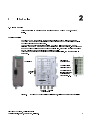
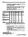


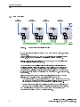
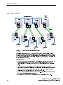

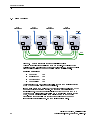

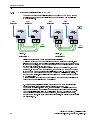
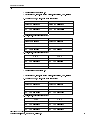
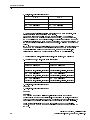
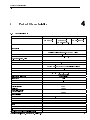
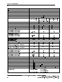
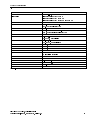

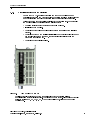

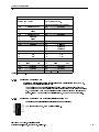


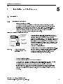
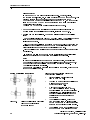

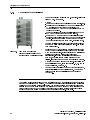

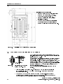

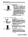
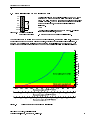


![WLg-ABOARD /N[P] - ACKSYS Communications & Systems](http://vs1.manualzilla.com/store/data/006361248_1-d85c19beabe1f63c614e17883b6a3a3e-150x150.png)