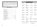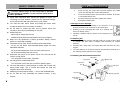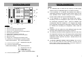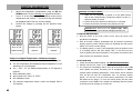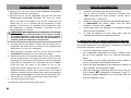
1
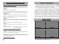
REPLACEMENT AIR NOZZLES
AOYUE
®
INT 2702A+
Lead-Free
Repairing System
INSTRUCTION MANUAL
Thank you for purchasing Aoyue Int2702A+ Repairing System.
It is important to read the manual before using the equipment.
Please keep manual in accessible place for future reference.
(*) Sold Separately
Manufacturer:
AOYUE TONGYI ELECTRONIC EQUIPMENT FACTORY
Jishui Industrial Zone, Nantou, Zhongshan City,
Guangdong Province, P.R.China
http://www.aoyue.com
24
This manual is designed to familiarize and instruct the operator with the proper usage and maintenance of the
equipment. The “Care and Safety Precautions” section
explains the hazards of using any type of soldering or reworking device. Please read carefully and observe the
guidelines in order to maximize usage and minimize the
risk of injury or accidents .
REPLACEMENT TIPS
TABLE OF CONTENTS
Product Description
Specifications
……………………………………………… 3
…………………………………………………
Package Inclusion
……………………………………………
Functions and Features
Safety Precautions
3
4
…………………………………
5
…………………………………………
6
Assembly and Preparation
Control Panel Guide
………………………………
7
………………………………………
8
Operating Guidelines
…………………………………
Auto-Sleep Functions
…………………………………… 13—14
Digital Calibration
………………………………………… 15—17
Care and Maintenance
…………………………………… 18— 20
Basic Troubleshooting Guide
Replacement Tips
Air Nozzles
9—12
……………………… 21 — 22
………………………………………
………………………………………………
23
24
(*) Sold Separately
2
23
BASIC TROUBLESHOOTING GUIDE
PROBLEM 7: AIR PRESSURE LEVEL IS SIGNIFICANTLY LOW NO MATTER HOW
HIGH THE AIRFLOW LEVEL IS CALIBRATED
Case 1: Check the mains voltage (AC power source). If the voltage level falls significantly
low, about 15-20% lower than the standard, there will also be a noticeable drop in the air
PRODUCT DESCRIPTION
The Aoyue INT2702A+ Lead-Free Repairing System is a reworking
equipment that combines the functionality of Hot Air Gun, Soldering
Iron, Smoke Absorber, and Desoldering Gun in one package.
It has several safety features such as the auto-cooling process of
pressure level.
SOLUTION:
Please refer to your local power service provider.
the Hot Air Gun. This functionality protects the device (and its
components) from excessive heat upon reaching any of the following
Case 2: The microcontroller might have detected the operating frequency incorrectly. The
conditions: (1) when the soldering gun remained idle on its resting
user will notice that airflow level is weaker with reference to the airflow gauge compared
handle after a certain period and (2) when the temperature of the
with the displayed value.
device is above a safe threshold upon turning off. It has several
SOLUTION:
Turn off the unit and on again to let the device re-detect the proper operating frequency.
advanced features such as solder iron digital calibration, configurable
Case 3:
design with digital control panel and display provides precision, safety,
The Suction Vacuum cap is connected to the Smoke Absorber Terminal or
auto sleep for hot-air and soldering iron. Finally, the unique, innovative
Vacuum cap instead of the Wire mesh cap.
SOLUTION:
Change the cap to the Wire mesh cap. This allows more air to pass through the system.
SPECIFICATION
Make sure as well that the vacuum tube of the soldering iron or desoldering gun is not
connected.
Case 4:
MAIN STATION
The Wire mesh cap is connected but airflow level is still low.
Power Input :
SOLUTION:
Station Dimensions:
Check the filter pad inside for dirt that can block the air passage. Clean or replace if
Weight:
necessary.
ADDITIONAL SOLUTION:
Check for any tangles in the tube of the hot air gun
PROBLEM 8: UNIT SHOWS UNCONVENTIONAL BEHAVIOR
Description: Unit operates erratically.
5.6Kg
Power Consumption:
70W
Temperature Range:
200°C - 480°C
Heating Element:
Ceramic Heater
Output Voltage:
Power Consumption:
Temperature Range:
the main power source and plug in again when necessary
Heating Element
Pump/Motor Type:
SOLUTION2: Restore unit to default factory setting. switch off/on the unit while holding
the hot-air temperature down button until the banner finishes scrolling, the unit would
revert to its default factory setting.
OTHER PROBLEMS NOT MENTIONED:
24V
HOT AIR GUN
SOLUTION1: Try to switch OFF the device and switch ON again. Unplug the system from
22
188(w) x 126(h) x 250(d) mm
SOLDERING IRON
that can cause the air blockage.
Contact the vendor.
available in 110V / 220V
Air Capacity:
500W
100°C - 480°C
Metal Heating Core
Diaphragm Pump
23 l /min (max)
DESOLDERING GUN
Temperature Range:
200°C - 480°C
Heating Element:
Ceramic Heater
Output Voltage:
Specifications are subject to change without prior notice.
24V
3
PACCKAGE INCLUSIONS
BASIC TROUBLESHOOTING GUIDE
PROBLEM 1: THE UNIT HAS NO POWER
939 Vacuum Suction Pen
2702 Main Station
G001 IC Popper
1.
Check if the unit is switched ON.
2.
Check the fuse. Replace with the same type if fuse is blown.
3.
Check the power cord and make sure there are no disconnections.
4.
Verify that the unit is properly connected to the power source.
PROBLEM 2: HOT-AIR GUN TEMPERATURE DISPLAY IS ALWAYS ABOVE 500oC
Description: Constant display of above 500oC temperature from the panel then displays
an “Err1” on the panel after a few minutes.
Hot Air Gun and
Hot Air Gun Holder
SOLUTION:
LF-2B Tip with
Heater Cartridge
The thermal sensor may be broken and needs to be replaced.
PROBLEM 3: HOT-AIR GUN ACTUAL AIR TEMPERATURE IS NOT INCREASING
30150J
Heat Resistant Pad
Soldering Iron with
Smoke Absorber
Description: Actual temperature reading is not increasing or decreasing based on
desired level.
SOLUTION:
The heating element may be broken or is at the end of its life and needs to be replaced.
PROBLEM 4: THE UNIT IS VIBRATING TOO MUCH
SOLUTION: Check if the 4 screws that hold the pump in place are properly and tightly
20125 Filter
Spring
Desoldering tips
connected. Unplug the system from the main power source before opening the case to
check inside the station.
PROBLEM 5: THE UNIT IS VERY NOISY
SOLUTION:
Desoldering Gun
and Holder
201242 Nozzle
cleaning pin
3017J Filter
Pads(6 pcs.)
Make sure the screw at the center of the base of the main unit has been removed. This
holds the pump in place during transportation and needs to be removed before using the
equipment.
PROBLEM 6: SOLDERING IRON TEMPERATURE DISPLAY PANEL SHOWS “PLUG”
Filter Vacuum Cap
2630B Soldering Iron Holder
with Solder Wire Stand
CHARACTERS
Case 1:
Suction Vacuum Cap
The system shows “PLUG” from the soldering iron temperature display
panel .
SOLUTION 1:
Check if the soldering iron connection assembly is properly connected
and secured to the receptacle on the control panel.
SOLUTION 2:
Power Cord
Air Nozzles
(1124, 1130, 1197, 1313, 1919,1010)
SOLUTION 3:
4
Make sure the soldering iron tip is properly inserted and secured inside
the handle. Loose contacts between the tip and handle can also cause this error message.
See “Soldering Iron Error Messages” on page 21 for further details.
21
CARE and MAINTENANCE
FUNCTION and FEATURES
Changing nozzle:
●
Unscrew the securing lock and pull out the heater external housing together
with the securing lock, Nozzle can now be changed. Re-secure nozzle by
tighten the securing lock on its receptacle.
Changing Filter pad and Filter Spring:
●
Unlock the filter dock by toggling the filter dock locking mechanism. The filter
dock would push out to allow easy extraction of the filter barrel assembly
which houses the filter pad, filter spring and filter barrel cap.
●
Microprocessor-controlled ESD safe equipment.
●
3-in-1 repairing system combining Hot Air Gun, Soldering Iron, and
Desoldering Gun in one sophisticated package.
●
temperature, desoldering gun temperature and air pressure with
touch type panel controls for precision and ease of use.
●
The desoldering gun is equipped with air cylinder type vacuum
pump for stronger suction and zero-crossing circuit that prevents
Filter Barrel Assembly
Filter Dock
Digital control and display of hot air temperature, soldering iron
electrical surges.
●
Filter Dock
Integrated smoke absorber functionality with filter pad to
efficiently absorb and filter harmful fumes.
●
Uniquely designed compound tip that integrates the ceramic
heating element and sensor in just one component. Replacing tips
is as easy as slipping it in/out of the compatible 24V soldering iron.
●
Filter dock locking
mechanism
User configurable 1 to 30 minute idle-to-auto-stand-by mode (with
5 minutes as default) for additional device protection and power
saving.
●
Built-in auto-cooling process that protects the system and its
components from excessive heat, prolonging usage life.
After extracting the Filter Barrel
Assembly we can now take out the
filter spring or the filter pads for
cleaning or replacement.
●
Built-in auto-sleep mode for soldering iron and desoldering gun.
●
Compatibility with air nozzles of various types.
●
Compatibility with different kind of soldering tips.
Re-assemble Filter Barrel assembly
attach spring filter to the filter barrel cap and place back to the desoldering gun body.
Push the Filter dock back in place
a “click” sound would signify that
the filter dock is properly secured.
20
5
CARE and MAINTENANCE
SAFETY PRECAUTIONS
CAUTION: Improper usage can cause serious injury to personnel
and/or damage to equipment. For your own safety, please observe
the ff. precautions.
●
Check each component after opening the package to make sure
everything is in good condition. If there are any suspected damage,
4.
Inside the pipe, the quartz glass and heat insulation are installed.
Loosen the cable and take out the heating element.
5.
Insert new heating element and reconnect the terminal. Be careful not
to rub Heating Element wire.
6.
Reconnect the ground wire after replacing the element.
7.
Assemble the handle again.
do not use the item and report the issue to your vendor.
●
Turn OFF the main power switch and unplug the device when
moving the device from one location to another.
●
Do not strike or subject the main unit to physical shock. Use
carefully to avoid injury and damage to any part.
●
Handle with care.
- Never drop or sharply jolt the unit.
- Contains delicate parts that may break if the unit is dropped.
●
Make sure the equipment is always grounded. Always connect
power to a grounded receptacle.
●
Temperature may reach as high as 480°C when switched ON.
- Do not use the device near flammable gases, paper and other
flammable materials.
- Do not touch heated parts, which can cause severe burns.
- Do not touch metallic parts near the tip.
●
Disconnect the plug from the power source if the unit will not be
used for a long period.
Soldering Iron Error Messages
1. Soldering Iron connection assembly is not connected or not
properly connected to the receptacle on the control panel.
2. Soldering iron tip is damaged and needs to be replaced. The
device will display “PLUG”.
3. Indicating a problem with the contacts of the soldering iron or
the tip.
De-Soldering Gun
1. Before usage dampen the filter pads with a little bit of water to allow efficient
air passage and filter action, re-dampen pads frequently for maximum
efficiency.
2. Routinely clean Spring Filter, and replace filter pads when they are dirty or
clogged .
3. The solder pathway can be cleaned using the provided Nozzle cleaning pin, use
the cleaning pin when pathway seems clogged.
De-Soldering Gun Disassembled illustration:
Filter Barrel
- Turn off power during breaks, if possible.
●
- Turn off power and let the unit cool before replacing parts.
●
The unit may produce a small amount of smoke and unusual odor
Filter Pads
Spring Filter
Use only genuine replacement parts.
Filter barrel
cap
Filter Dock
during initial usage. This is normal and should not yield any
negative result when reworking.
●
Soldering process produces smoke — use on well ventilated place.
●
Do not alter the unit, specifically the internal circuitry, in any
manner.
6
Securing lock
Heater external
housing
De-soldering Gun Body
Nozzle
Heating
element
19
CARE and MAINTENANCE
Spare Parts Guide
Part No.
10094
30106S
S009
20962
B012
C005
3072D
B1003
ASSEMBLY and PREPARATIONS
A. Main Station
Description
Hot air gun heating element
Plastic handle of hot air gun
Hot air gun complete handle
Hot air gun metal pipe
Soldering Iron complete handle
Desoldering gun heating element
Plastic handle of desoldering gun
Desoldering gun complete handle
As soon as the equipment has been removed from the package,
REMOVE THE SCREW located at the center of the bottom of the
main unit. This screw holds the pump in place during transportation.
WARNING: Failure to remove the screw before using the
equipment can cause damage to the system.
B. Soldering Iron
1. Install the solder wire to the soldering iron holder as in Figure 1.
Blower/Vacuum Air Terminal Filters
Filters should be cleaned and replaced regularly to avoid dirt which can clog the
air passage. More importantly, this will also effectively clean the toxic fumes
produced during soldering process.
Soldering Iron Tip
Always keep the solder-plated section of the tip/nozzle coated with a small
amount of solder. Oxide coating on the tip of the nozzle reduces its heat
conductivity. Coating the tip with a small amount of fresh solder ensures
maximum heat conductivity is obtained.
Replacing the Soldering Iron tip
1. Always turn OFF main power switch when removing or inserting a tip.
2. If the tip is hot, use the heat resistant pad to pull it out.
3. Insert the new tip fully into the handle. If the tip is not fully inserted (or if
the tip is damaged), the device will display “PLUG”. Indicating a problem
with the contacts of the soldering iron or the tip.
Replacing the heating element of the Hot Air Gun
The heating element is found in the middle part of the hot air gun. The
normal life of a heating element is 1 year under normal operating conditions.
Steps:
1. Loosen the 3 screws that secure the handle.
2. Slide off the plastic tube.
3. Disconnect the ground wire sleeve.
18
Figure 1. Soldering iron stand with solder wire holder
2. Connect the soldering iron cord assembly to the 6-pin output
terminal found at the lower middle portion of the main unit.
3. Place the soldering iron to the soldering iron stand as shown
above.
C. Smoke Absorber
1. Attach the smoke absorbing tube to the suction vacuum cap.
Make sure the cord connections are free from tangles.
D. Hot Air Gun
The Hot Air Gun holder was installed on the station upside down for
packaging purpose. To set up the Hot Air Gun holder:
1. Loosen the two screws that secure the holder to the station.
2. Turn the holder right side up.
3. Re-fasten the two screws.
4. Place the hot air gun onto the holder in preparation for usage.
E. Desoldering Gun
1. Connect the cord of the desoldering gun to the 6-pin terminal .
2. Connect the vacuum tube to the suction vacuum cap.
3. Place the desoldering gun onto the holder in preparation for
usage.
7
CONTROL PANEL GUIDE
DIGITAL CALIBRATION
NOTES:
1
2
13
3
12
10
4
14
11
●
The calibrated data is saved into the memory an shall remain
effective until it is recalibrated again or new data is entered.
●
If the maximum of 70 degrees has already been added or
subtracted pressing the air pressure down button would not exit
from calibration mode. Instead turning off the soldering iron
9
function switch would exit from the calibration mode.
●
If the maximum of 70 degrees has already been added ,
increasing further the temperature offset would not be allowed
8
but subtracting temperature offset
would be available. And
consequently when the maximum of 70 degrees has already
5
6
been subtracted, decreasing the temperature offset further would
7
LEGEND:
be disabled but increasing the temperature offset would be
1 — Airflow Gauge
allowed.
2 — Hot Air Gun Temperature Adjustment Buttons
●
3 — Hot Air Gun Airflow Adjustment Buttons
Calibration will only make the newly calibrated point the most
accurate. Other temperature points may be a little off.
4 — Soldering Iron / Desoldering Gun Temp Control Buttons
5 — Hot Air Gun Output Terminal
●
The soldering Iron has a lowest temperature limit such that when
6 — Smoke Absorber Terminal or Vacuum Cap
the temperature has been set to 200 degrees with external actual
7 — Soldering Iron / Desoldering Gun 6-Pin Receptacle
temperature also showing 200 degrees, further decreasing the
8 — Main Power Switch
temperature offset would be only have
9 — Soldering Iron / Desoldering Gun Activation Switch
10 — Soldering Iron / Desoldering Gun Temperature Display
Prefixes and meanings:
●
“H” - actual temperature
To reset the calibration settings to factory setting, switch off and on
the unit and while holding the hot-air temperature up button until the
“h” - temperature being set
banner finishes scrolling, the Set temperature / Temperature calibration of
12 — Hot Air Gun Air flow Display
the unit would revert to its default factory setting.
13 — Hot Air Gun Temperature Display
Prefixes and meanings:
minimal effect to the
actual temperature.
“H” - actual temperature
“h” - temperature being set
“C” - cooling down
“---” - sleep mode display
“OFF” - function deactivated display
14 — Hot Air Gun Activation Switch
8
17
DIGITAL CALIBRATION
6.
OPERATING GUIDELINES
Adjust the temperature compensation using the UP and
DOWN buttons of the Soldering iron adjustment buttons.
7.
A zero “0” on the first digit signifies addition to the current
temperature and a minus “-” on the first digit will subtract
the displayed value from the current settings.
8.
Confirm the change by pressing the air pressure down
IMPORTANT REMINDERS:
1. Make sure the equipment is placed on a flat stable surface
and all the heat-generating components placed on their respective holders or stands.
2. Ensure all function switches are OFF prior to reworking.
3. Ensure all terminal connections are properly secured.
button.
IMPORTANT: Please refer to the CONTROL PANEL GUIDE
page for buttons and display panel directory.
A. INITIAL PROCEDURES
1. Plug the device to the main power source using the power cord
provided in the package.
2. With all function switches deactivated and all terminal connections
Initial display
Increase tem-
Decrease tem-
when in cali-
perature by 38
perature by 30
bration mode
degrees
degrees
properly secured, switch ON the device by activating the main power
switch (“8” from the control panel).
3. The display panels, 11 and 12 will temporarily show the product name
in a scrolling manner and then display “OFF” on all rows once the
scroll is finished (see below illustration). The system will remain at this
state until the user activates a function.
Solder Iron Digital Temperature Calibration Example
●
The external temperature sensor displays 248 to 252 degrees.
●
The set temperature and displayed actual temperature of the
soldering iron is 300 degrees.
●
300 — 248 = 52. An additional adjustment of 52 degrees is
required.
●
Enter calibration mode
●
We increase from “0000” to “0052”.
●
Exit calibration mode.
●
The external temperature sensor would now display 298 to
302 degrees.
16
B. HOT AIR GUN
1. Follow the initial procedures above, “A. INITIAL PROCEDURES”.
2. Activate “Hot Air Gun” switch (“14” from the control panel).
3. The system will immediately start to blow air at an airflow rate of 50
while rapidly and safely increasing the air temperature to 100°C
(default system operating parameters). These values will be reflected
from the Hot Air Gun Air Temperature and
Air Pressure display
panels, “13” and “12” from the control panel, respectively. The metal
ball inside the air gauge (“1” from the control panel) will also settle
somewhere in the middle of the visible area indicating that the system
is blowing air at an average or normal rate.
9
OPERATING GUIDELINES
4. Adjust the air flow level using the AIR PRESSURE ADJUSTMENT
BUTTONS (“3” from the control panel).
DIGITAL CALIBRATION
3.
Release the two buttons after the change in display.
4.
Use the same two buttons to adjust the countdown time.
5. Adjust the hot air gun air temperature using the HOT AIR GUN
“t001” means solder iron will go to sleep in 1 minute. Timer is
TEMPERATURE ADJUSTMENT BUTTONS (“2” from the control
panel). The prefix of the display for Hot Air Gun Temperature will
change from “H” to “h” indicating that air temperature is being
adjustable from 1 to 60minutes.
5.
6.
adjusted. It will return to “H” (indicating actual temperature) while
the temperature is gradually increasing or decreasing until the
advised to initially increase the airflow level in order to manage
the system temperature. This is to protect the heating element
inside the handle from excessive heat and avoid the possibility of
subjecting adjacent components to thermal shock.
6. Reworking task can be started 1 minute after the desired hot air
temperature and airflow level are reached, as also indicated from
display panels “11” and “12”, respectively.
7. When reworking is complete, return the Hot Air Gun to its holder
and DO NOT immediately turn off the main power switch.
8. Deactivate the Hot Air Gun Activation button first in order to activate
the auto-cooling process. The system will start to blow air (at room
temperature) at a fast rate to reduce heat from the hot air gun and
bring down the temperature to a reasonable safe level of 90°C.
During this time, the prefix of the display for hot air gun
temperature will also change from “H” to “C” while temperature is
To DEACTIVATE this feature, simply follow the above
procedures. This time, select “tOFF” .
7.
desired temperature is reached.
IMPORTANT: When adjusting the air temperature, it is strongly
Confirm the change by activating the SOLDERING IRON switch.
During sleep mode, the soldering iron temperature display
panel will show an all-dash, “- - - - ” .
8.
To wake the soldering iron from sleep mode, press the
soldering iron temperature adjustment buttons.
H. Utilizing the Solder Iron Digital Temperature Calibration
By default, the system is properly calibrated but for some cases
when a little adjustment of the soldering iron temperature is required
the following procedure can be done.
1. Turn on the soldering iron function switch.
2. Set to appropriate temperature you want to calibrate. Place
the tip of the soldering iron on an external temperature
sensor.
3. The readings on the external temperature sensor should be
more or less equal to the displayed temperature.
4. If there are large discrepancy in the temperature reading we
can re-calibrate the temperature setting.
gradually decreasing. Likewise, the air pressure level is at its highest
5. While the solder iron is operating make sure the hot air gun
reading as indicated from the display panel. Once the temperature
is in off mode (“0FF” is displayed on the panels “6” and “7”),
drops to approximately 90°C the system will halt and display “OFF”
hold the air pressure UP button for a few seconds until four
on the panel. It is now safe to switch off the main power switch.
zeroes are displayed “0000” .
9. Turn OFF the main power switch.
10. Unplug the device from the main power source.
10
15
AUTO SLEEP FUNCTIONS
OPERATING GUIDELINES
1. While the hot air gun is on stand-by mode (“0FF” is displayed on
the panels “13” and “12”), hold both UP and DOWN buttons of
the HOT AIR GUN TEMPERATURE adjustment buttons.
2. Wait until “t005” is displayed on the Hot Air Gun Temperature
display panel, “13”.
NOTES:
1. Hot Air Gun Temperature is adjustable between 100°
and 480°C with an increment of 2° on each step.
2. Hot Air Gun Airflow Rate is adjustable between 10
and 100 with an increment of 2 on each step.
3. Release the buttons when “t005” appears.
C. SOLDERING IRON
4. Adjust the time using the same UP and DOWN buttons of the
1. Connect the Soldering Iron connection assembly to the 6-pin
receptacle located at the front of the control panel (“7” from the
HOT AIR GUN TEMPERATURE adjustment buttons.
5. Confirm the change by activating the HOT AIR GUN function
CONTROL PANEL GUIDE).
2. Follow the initial procedures (“A. INITIAL PROCEDURES”).
switch.
6. The system will immediately switch back to operation and use the
3. Connect the vacuum tube to the Smoke Absorber Terminal or
Vacuum Cap (“6” from the control panel). If smoke absorber
defined countdown parameter for the entire usage.
function is to be used.
NOTES:
●
The sleep mode timer is configurable between 1 and 30 minutes.
●
Sleep mode settings for Hot-Air gun and Soldering Iron is saved
into the memory an shall remain effective until it is reset or new
4. Activate the “SOLDER IRON” Activation switch (“9” from control
panel). This will automatically start to increase the temperature of
the soldering iron to 350°C (default).
5. Adjust the soldering iron temperature using the SOLDER/DESOLDER
data is entered.
TEMPERATURE ADJUSTMENT buttons (“4” from the control panel).
6. If smoke absorber function is to be used. Activate the “SMOKE
G. Activating Soldering Iron Auto-Sleep Mode
The soldering iron’s SLEEP mode is deactivated by default. Follow
the set of procedures below to activate this feature.
reached.
CONDITION: SOLDERING IRON function is inactive.
1. While soldering iron is displaying “OFF” or in stand-by mode, push
both
UP
and
DOWN
buttons
of
the
ABSORBER” Activation switch (“11” from the control panel).
7. Start using the soldering iron as soon as desired temperature is
SOLDERING
IRON
TEMPERATURE adjustment buttons (“4” from the CONTROL PANEL
GUIDE page).
2. Wait until “t0FF” appears from soldering iron temperature display
panel. This means sleep mode is currently turned OFF.
8. When the task is finished, deactivate the SMOKE ABSORBER switch.
9. Deactivate the SOLDER IRON activation switch.
10. Allow sufficient time for the soldering iron to cool down before
keeping in a safe storage.
D. DESOLDERING GUN
1. Connect the De-soldering gun connection assembly to the 6-pin
receptacle located at the front of the control panel (“7” from the
CONTROL PANEL GUIDE).
2. Follow the initial procedures (“A. INITIAL PROCEDURES”).
14
11
OPERATING GUIDELINES
3. Connect the vacuum tube to the Smoke Absorber Terminal or
AUTO SLEEP FUNCTIONS
●
Vacuum Cap (“6” from the control panel). If smoke absorber
function is to be used.
4. Activate the “SOLDER IRON” Activation switch (“9” from control
panel). This will automatically start to increase the temperature of
the desoldering gun to 350°C (default).
6. Adjust the desoldering gun temp. using the SOLDER/DESOLDER
TEMPERATURE ADJUSTMENT buttons (“4” from the control panel).
7. Allow the desoldering gun's tip and its barrel to heat up. Tip
temperature can be reached within 5-6 minutes and its barrel would
obtain optimum temperature 5-9 minutes after the tip temperature
has been reached. If upon initial use solder gets stuck at the end of
the barrel, clean the barrel and wait a few more minutes for the
barrel to heat up.
8. Check the tip temperature with an external temperature sensor,
adjust temperature settings higher or lower for the right
temperature. Or recalibrate at the desired temperature level
9. Ensure that all the solder is melted before triggering the pump.
(Partially melted solder will still be sucked up however it would clog
the barrel).
10. Upon pressing the pump trigger hold the trigger for 1 to 2
seconds longer, as larger lumps of solder may need a longer suction
time to clear the barrel and go into the filter.
11. Clean the filter and dampen the sponge frequently during and after
usage to allow better suction power.
12. When the task is finished, deactivate the SOLDER IRON switch.
Allow the desoldering gun to cool down before handling for storage.
Notes:
●
Please follow the procedures and tips presented above for more
efficient usage of the desoldering gun.
●
Industry recommended tip temperature for soldering is 600 to
610F (315 to 320C) for standard solders and 650 to 700F (340 to
370) for unleaded solders
12
The soldering iron and desoldering gun operating temperature is
configurable between 200°C and 480°C
●
Because of the difference in the heating element and size of the
soldering iron tip and desoldering gun, the soldering iron will heat
up faster than the desoldering gun. This is normal and does not
have any impact on the system’s performance.
●
There will be a slight drop in temperature display once the trigger
of the desoldering gun is used. This is due to rapid intake of air in
which temperature is significantly cooler than the desoldering gun
tip. When the system detects this, it will automatically adjust the
temperature to compensate for the temperature difference.
IMPORTANT: Make sure the SMOKE ABSORBER switch
is deactivated while using the desoldering gun. Otherwise, the desoldering gun will keep on sucking air indefinitely.
E. Auto-Sleep Mode (Hot Air Gun)
The device has a built-in auto-sleep mode feature such that if the
Hot Air Gun sits on its handle and remained idle after a certain period
(the prefix of the display for Hot Air Gun air temperature will also
change from “H” to “L”) , the device will switch to sleep mode. This
mechanism is triggered by a countdown timer so when the time has
elapsed, the system will blow air (at room temperature) at maximum
rate in order to bring down the temperature. During this time, the prefix
of the display for Hot Air Gun air temperature will also change from “L”
to “C”. Once the temperature drops to approximately 90°C, the Hot Air
Gun will automatically stop and show an all-dash “ - - - - “display
indicating that the system is now on sleep mode.
F. Changing SLEEP Mode Timer (HOT AIR GUN)
By default, the system has 5-minute countdown time before the
hot air gun goes to sleep mode. This can be altered by the following
procedure.
13