1
Cisco IOS
IP
Configuration Guide
Release 12.2
Corporate Headquarters
Cisco Systems, Inc.
170 West Tasman Drive
San Jose, CA 95134-1706
USA
http://www.cisco.com
Tel: 408 526-4000
800 553-NETS (6387)
Fax: 408 526-4100
Customer Order Number: DOC-7811741=
Text Part Number: 78-11741-02
THE SPECIFICATIONS AND INFORMATION REGARDING THE PRODUCTS IN THIS MANUAL ARE SUBJECT TO CHANGE WITHOUT
NOTICE. ALL STATEMENTS, INFORMATION, AND RECOMMENDATIONS IN THIS MANUAL ARE BELIEVED TO BE ACCURATE BUT ARE
PRESENTED WITHOUT WARRANTY OF ANY KIND, EXPRESS OR IMPLIED. USERS MUST TAKE FULL RESPONSIBILITY FOR THEIR
APPLICATION OF ANY PRODUCTS.
THE SOFTWARE LICENSE AND LIMITED WARRANTY FOR THE ACCOMPANYING PRODUCT ARE SET FORTH IN THE INFORMATION
PACKET THAT SHIPPED WITH THE PRODUCT AND ARE INCORPORATED HEREIN BY THIS REFERENCE. IF YOU ARE UNABLE TO
LOCATE THE SOFTWARE LICENSE OR LIMITED WARRANTY, CONTACT YOUR CISCO REPRESENTATIVE FOR A COPY.
The Cisco implementation of TCP header compression is an adaptation of a program developed by the University of California, Berkeley (UCB) as part of
UCB’s public domain version of the UNIX operating system. All rights reserved. Copyright © 1981, Regents of the University of California.
NOTWITHSTANDING ANY OTHER WARRANTY HEREIN, ALL DOCUMENT FILES AND SOFTWARE OF THESE SUPPLIERS ARE PROVIDED
“AS IS” WITH ALL FAULTS. CISCO AND THE ABOVE-NAMED SUPPLIERS DISCLAIM ALL WARRANTIES, EXPRESSED OR IMPLIED,
INCLUDING, WITHOUT LIMITATION, THOSE OF MERCHANTABILITY, FITNESS FOR A PARTICULAR PURPOSE AND
NONINFRINGEMENT OR ARISING FROM A COURSE OF DEALING, USAGE, OR TRADE PRACTICE.
IN NO EVENT SHALL CISCO OR ITS SUPPLIERS BE LIABLE FOR ANY INDIRECT, SPECIAL, CONSEQUENTIAL, OR INCIDENTAL
DAMAGES, INCLUDING, WITHOUT LIMITATION, LOST PROFITS OR LOSS OR DAMAGE TO DATA ARISING OUT OF THE USE OR
INABILITY TO USE THIS MANUAL, EVEN IF CISCO OR ITS SUPPLIERS HAVE BEEN ADVISED OF THE POSSIBILITY OF SUCH DAMAGES.
AccessPath, AtmDirector, Browse with Me, CCDA, CCDE, CCDP, CCIE, CCNA, CCNP, CCSI, CD-PAC, CiscoLink, the Cisco NetWorks logo, the Cisco
Powered Network logo, Cisco Systems Networking Academy, the Cisco Systems Networking Academy logo, Fast Step, Follow Me Browsing, FormShare,
FrameShare, GigaStack, IGX, Internet Quotient, IP/VC, iQ Breakthrough, iQ Expertise, iQ FastTrack, the iQ Logo, iQ Net Readiness Scorecard, MGX,
the Networkers logo, Packet, PIX, RateMUX, ScriptBuilder, ScriptShare, SlideCast, SMARTnet, TransPath, Unity, Voice LAN, Wavelength Router, and
WebViewer are trademarks of Cisco Systems, Inc.; Changing the Way We Work, Live, Play, and Learn, Discover All That’s Possible, and Empowering
the Internet Generation, are service marks of Cisco Systems, Inc.; and Aironet, ASIST, BPX, Catalyst, Cisco, the Cisco Certified Internetwork Expert logo,
Cisco IOS, the Cisco IOS logo, Cisco Systems, Cisco Systems Capital, the Cisco Systems logo, Enterprise/Solver, EtherChannel, EtherSwitch, FastHub,
FastSwitch, IOS, IP/TV, LightStream, MICA, Network Registrar, Post-Routing, Pre-Routing, Registrar, StrataView Plus, Stratm, SwitchProbe, TeleRouter,
and VCO are registered trademarks of Cisco Systems, Inc. or its affiliates in the U.S. and certain other countries.
All other brands, names, or trademarks mentioned in this document or Web site are the property of their respective owners. The use of the word partner
does not imply a partnership relationship between Cisco and any other company. (0102R)
Cisco IOS IP Configuration Guide
Copyright © 2001–2006, Cisco Systems, Inc.
All rights reserved.
CONTENTS
About Cisco IOS Software Documentation
Documentation Objectives
Audience
xxix
xxix
xxix
Documentation Organization xxix
Documentation Modules xxix
Master Indexes xxxii
Supporting Documents and Resources
New and Changed Information
Document Conventions
xxxii
xxxiii
xxxiii
Obtaining Documentation xxxv
World Wide Web xxxv
Documentation CD-ROM xxxv
Ordering Documentation xxxv
Documentation Feedback
xxxv
Obtaining Technical Assistance xxxvi
Cisco.com xxxvi
Technical Assistance Center xxxvi
Contacting TAC by Using the Cisco TAC Website
Contacting TAC by Telephone xxxvii
Using Cisco IOS Software
xxxvi
xxxix
Understanding Command Modes
xxxix
Getting Help xl
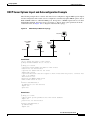
Example: How to Find Command Options
xli
Using the no and default Forms of Commands
xliii
Saving Configuration Changes
xliv
Filtering Output from the show and more Commands
xliv
Identifying Supported Platforms xlv
Using Feature Navigator xlv
Using Software Release Notes xlv
IP Overview
IPC-1
IP Addressing and Services
IP Routing Protocols
IPC-1
IPC-2
Cisco IOS IP Configuration Guide
iii
Contents
Determining a Routing Process IPC-2
Interior and Exterior Gateway Protocols IPC-2
Interior Gateway Protocols IPC-3
Exterior Gateway Protocols IPC-3
Multiple Routing Protocols IPC-3
IP Multicast
IPC-4
IP ADDRESSING AND SERVICES
Configuring IP Addressing
IP Addressing Task List
IPC-7
IPC-7
Assigning IP Addresses to Network Interfaces IPC-7
Assigning Multiple IP Addresses to Network Interfaces
Enabling Use of Subnet Zero IPC-9
Disabling Classless Routing Behavior IPC-10
Enabling IP Processing on a Serial Interface IPC-11
IPC-9
Configuring Address Resolution Methods IPC-12
Establishing Address Resolution IPC-12
Defining a Static ARP Cache IPC-13
Setting ARP Encapsulations IPC-14
Enabling Proxy ARP IPC-14
Configuring Local-Area Mobility IPC-15
Mapping Host Names to IP Addresses IPC-15
Assigning Host Names to IP Addresses IPC-16
Specifying the Domain Name IPC-16
Specifying a Name Server IPC-17
Enabling the DNS IPC-17
Using the DNS to Discover ISO CLNS Addresses IPC-17
Configuring HP Probe Proxy Name Requests IPC-18
Configuring the Next Hop Resolution Protocol IPC-18
The Cisco Implementation of NHRP IPC-18
Protocol Operation IPC-20
NHRP Configuration Task List IPC-20
Enabling NHRP on an Interface IPC-21
Configuring a Static IP-to-NBMA Address Mapping for a Station
Statically Configuring a Next Hop Server IPC-21
Configuring NHRP Authentication IPC-22
Controlling the Triggering of NHRP IPC-22
Triggering NHRP Based on Traffic Thresholds IPC-23
Controlling the NHRP Packet Rate IPC-25
Cisco IOS IP Configuration Guide
iv
IPC-21
Contents
Suppressing Forward and Reverse Record Options IPC-26
Specifying the NHRP Responder Address IPC-26
Changing the Time Period NBMA Addresses Are Advertised as Valid
Configuring a GRE Tunnel for Multipoint Operation IPC-27
Configuring NHRP Server-Only Mode IPC-27
Enabling IP Routing IPC-27
Routing Assistance When IP Routing Is Disabled
Proxy ARP IPC-28
Default Gateway IPC-28
ICMP Router Discovery Protocol IPC-29
Enabling IP Bridging
IPC-26
IPC-28
IPC-30
Enabling Integrated Routing and Bridging
Configuring a Routing Process
IPC-30
IPC-30
Configuring Broadcast Packet Handling IPC-31
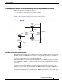
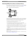
Enabling Directed Broadcast-to-Physical Broadcast Translation
Forwarding UDP Broadcast Packets and Protocols IPC-32
Establishing an IP Broadcast Address IPC-33
Flooding IP Broadcasts IPC-33
Speeding Up Flooding of UDP Datagrams IPC-34
IPC-31
Configuring Network Address Translation IPC-35
NAT Applications IPC-35
Benefits IPC-35
NAT Terminology IPC-36
NAT Configuration Task List IPC-36
Translating Inside Source Addresses IPC-37
Configuring Static Translation IPC-38
Configuring Dynamic Translation with an Access List IPC-38
Configuring Dynamic Translation with a Route Map IPC-39
Overloading an Inside Global Address IPC-39
Translating Overlapping Addresses IPC-41
Configuring Static Translation IPC-43
Configuring Dynamic Translation IPC-43
Providing TCP Load Distribution IPC-43
Changing Translation Timeouts IPC-45
Monitoring and Maintaining NAT IPC-46
Deploying NAT Between an IP Phone and Cisco CallManager IPC-46
Monitoring and Maintaining IP Addressing IPC-47
Clearing Caches, Tables, and Databases IPC-47
Specifying the Format of Network Masks IPC-47
Cisco IOS IP Configuration Guide
v
Contents
Displaying System and Network Statistics IPC-48
Monitoring and Maintaining NHRP IPC-49
IP Addressing Examples IPC-49
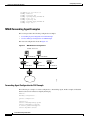
Creating a Network from Separated Subnets Example IPC-50
Serial Interfaces Configuration Example IPC-50
IP Domains Example IPC-51
Dynamic Lookup Example IPC-51
HP Hosts on a Network Segment Example IPC-51
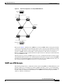
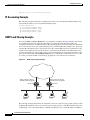
Logical NBMA Example IPC-51
NHRP over ATM Example IPC-53
Changing the Rate for Triggering SVCs Example IPC-55
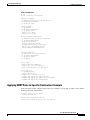
Applying NHRP Rates to Specific Destinations Example IPC-57
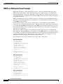
NHRP on a Multipoint Tunnel Example IPC-58
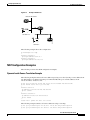
Broadcasting Examples IPC-59
Flooded Broadcast Example IPC-59
Flooding of IP Broadcasts Example IPC-60
Helper Addresses Example IPC-60
NAT Configuration Examples IPC-61
Dynamic Inside Source Translation Example IPC-61
Overloading Inside Global Addresses Example IPC-62
Translating Overlapping Address Example IPC-62
TCP Load Distribution Example IPC-63
ping Command Example IPC-63
Configuring DHCP
IPC-65
DHCP Server Overview
IPC-65
DHCP Client Overview
IPC-67
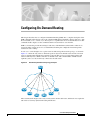
DHCP Relay Agent Overview
IPC-67
DHCP Configuration Task List IPC-68
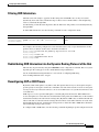
Enabling the Cisco IOS DHCP Server and Relay Agent Features IPC-68
Configuring a DHCP Database Agent or Disabling DHCP Conflict Logging IPC-69
Excluding IP Addresses IPC-69
Configuring a DHCP Address Pool IPC-69
Configuring the DHCP Address Pool Name and Entering DHCP Pool Configuration Mode IPC-69
Configuring the DHCP Address Pool Subnet and Mask IPC-70
Configuring the Domain Name for the Client IPC-70
Configuring the IP Domain Name System Servers for the Client IPC-70
Configuring the NetBIOS Windows Internet Naming Service Servers for the Client IPC-70
Configuring the NetBIOS Node Type for the Client IPC-71
Configuring the Default Router for the Client IPC-71
Cisco IOS IP Configuration Guide
vi
Contents
Configuring the Address Lease Time IPC-71
Configuring Manual Bindings IPC-71
Configuring a DHCP Server Boot File IPC-73
Configuring the Number of Ping Packets IPC-73
Configuring the Timeout Value for Ping Packets IPC-73
Enabling the Cisco IOS DHCP Client on Ethernet Interfaces IPC-73
Configuring DHCP Server Options Import and Autoconfiguration IPC-74
Configuring the Relay Agent Information Option in BOOTREPLY Messages
Configuring a Relay Agent Information Reforwarding Policy IPC-75
Enabling the DHCP Smart-Relay Feature IPC-75
Monitoring and Maintaining the DHCP Server
IPC-75
Configuration Examples IPC-76
DHCP Database Agent Configuration Example IPC-77
DHCP Address Pool Configuration Example IPC-77
Manual Bindings Configuration Example IPC-78
Cisco IOS DHCP Client Example IPC-78
DHCP Server Options Import and Autoconfiguration Example
Configuring IP Services
IP Services Task List
IPC-75
IPC-79
IPC-81
IPC-81
Managing IP Connections IPC-81
Enabling ICMP Protocol Unreachable Messages IPC-82
Enabling ICMP Redirect Messages IPC-82
Enabling ICMP Mask Reply Messages IPC-83
Understanding Path MTU Discovery IPC-83
Setting the MTU Packet Size IPC-84
Enabling IP Source Routing IPC-84
Configuring Simplex Ethernet Interfaces IPC-85
Configuring a DRP Server Agent IPC-85
Enabling the DRP Server Agent IPC-86
Limiting the Source of DRP Queries IPC-86
Configuring Authentication of DRP Queries and Responses
IPC-86
Filtering IP Packets Using Access Lists IPC-87
Creating Standard and Extended Access Lists Using Numbers IPC-88
Creating Standard and Extended Access Lists Using Names IPC-91
Specifying IP Extended Access Lists with Fragment Control IPC-93
Benefits of Fragment Control in an IP Extended Access List IPC-95
Enabling Turbo Access Control Lists IPC-96
Configuring Turbo ACLs IPC-96
Verifying Turbo ACLs IPC-97
Cisco IOS IP Configuration Guide
vii
Contents
Applying Time Ranges to Access Lists IPC-97
Including Comments About Entries in Access Lists IPC-98
Applying Access Lists IPC-98
Controlling Access to a Line or Interface IPC-99
Controlling Policy Routing and the Filtering of Routing Information
Controlling Dialer Functions IPC-99
IPC-99
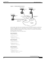
Configuring the Hot Standby Router Protocol IPC-100
Enabling HSRP IPC-101
Configuring HSRP Group Attributes IPC-102
Changing the HSRP MAC Refresh Interval IPC-102
Enabling HSRP MIB Traps IPC-103
Enabling HSRP Support for MPLS VPNs IPC-103
Defining VPNs IPC-104
Enabling HSRP IPC-104
Verifying HSRP Support for MPLS VPNs IPC-105
Enabling HSRP Support for ICMP Redirect Messages IPC-105
Redirects to Active HSRP Routers IPC-105
Redirects to Passive HSRP Routers IPC-107
Redirects to Non-HSRP Routers IPC-107
Passive HSRP Router Advertisements IPC-107
Redirects Not Sent IPC-107
Configuring HSRP Support for ICMP Redirect Messages IPC-108
Configuring IP Accounting IPC-108
Configuring IP MAC Accounting IPC-109
Configuring IP Precedence Accounting IPC-110
Configuring TCP Performance Parameters IPC-110
Compressing TCP Packet Headers IPC-111
Expressing TCP Header Compression IPC-111
Changing the Number of TCP Header Compression Connections
Setting the TCP Connection Attempt Time IPC-112
Enabling TCP Path MTU Discovery IPC-112
Enabling TCP Selective Acknowledgment IPC-113
Enabling TCP Time Stamp IPC-114
Setting the TCP Maximum Read Size IPC-114
Setting the TCP Window Size IPC-114
Setting the TCP Outgoing Queue Size IPC-115
Configuring IP over WANs
IPC-115
Configuring the MultiNode Load Balancing Forwarding Agent IPC-115
MNLB Forwarding Agent Configuration Task List IPC-116
Cisco IOS IP Configuration Guide
viii
IPC-112
Contents
Enabling CEF IPC-116
Enabling NetFlow Switching IPC-117
Enabling IP Multicast Routing IPC-117
Configuring the Router as a Forwarding Agent
IPC-118
Monitoring and Maintaining the IP Network IPC-118
Clearing Caches, Tables, and Databases IPC-118
Monitoring and Maintaining the DRP Server Agent IPC-119
Clearing the Access List Counters IPC-119
Displaying System and Network Statistics IPC-119
Monitoring the MNLB Forwarding Agent IPC-120
Monitoring and Maintaining HSRP Support for ICMP Redirect Messages
IPC-120
IP Services Configuration Examples IPC-120
ICMP Services Example IPC-121
Simplex Ethernet Interfaces Example IPC-121
DRP Server Agent Example IPC-122
Numbered Access List Examples IPC-122
Turbo Access Control List Example IPC-123
Implicit Masks in Access Lists Examples IPC-123
Extended Access List Examples IPC-124
Named Access List Example IPC-124
IP Extended Access List with Fragment Control Example IPC-125
Time Range Applied to an IP Access List Example IPC-125
Commented IP Access List Entry Examples IPC-125
IP Accounting Example IPC-126
HSRP Load Sharing Example IPC-126
HSRP MAC Refresh Interval Examples IPC-127
No Switch or Learning Bridge Present Example IPC-127
Switch or Learning Bridge Present Example IPC-127
HSRP MIB Trap Example IPC-128
HSRP Support for MPLS VPNs Example IPC-128
HSRP Support for ICMP Redirect Messages Example IPC-129
MNLB Forwarding Agent Examples IPC-130
Forwarding Agent Configuration for FA2 Example IPC-130
Services Manager Configuration for SM Example IPC-131
Configuring Server Load Balancing
IPC-133
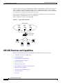
IOS SLB Functions and Capabilities IPC-134
Algorithms for Server Load Balancing IPC-135
Weighted Round Robin IPC-135
Weighted Least Connections IPC-135
Cisco IOS IP Configuration Guide
ix
Contents
Port-Bound Servers IPC-136
Client-Assigned Load Balancing IPC-136
Content Flow Monitor Support IPC-136
Sticky Connections IPC-136
Maximum Connections IPC-136
Delayed Removal of TCP Connection Context IPC-137
TCP Session Reassignment IPC-137
Automatic Server Failure Detection IPC-137
Automatic Unfail IPC-137
Slow Start IPC-137
SynGuard IPC-137
Dynamic Feedback Protocol for IOS SLB IPC-138
Alternate IP Addresses IPC-138
Transparent Web Cache Balancing IPC-138
NAT IPC-138
Redundancy Enhancement—Stateless Backup IPC-139
Restrictions
IPC-139
IOS SLB Configuration Task List IPC-140
Specifying a Server Farm IPC-141
Specifying a Load-Balancing Algorithm IPC-141
Specifying a Bind ID IPC-142
Specifying a Real Server IPC-142
Configuring Real Server Attributes IPC-142
Enabling the Real Server for Service IPC-143
Specifying a Virtual Server IPC-143
Associating a Virtual Server with a Server Farm IPC-143
Configuring Virtual Server Attributes IPC-143
Adjusting Virtual Server Values IPC-144
Preventing Advertisement of Virtual Server Address IPC-144
Enabling the Virtual Server for Service IPC-144
Configuring IOS SLB Dynamic Feedback Protocol IPC-145
Configuring NAT IPC-145
Implementing IOS SLB Stateless Backup IPC-145
How IOS SLB Stateless Backup Works IPC-145
Configuring IOS SLB Stateless Backup IPC-146
Enabling HSRP IPC-147
Customizing Group Attributes IPC-147
Verifying the IOS SLB Stateless Backup Configuration IPC-147
Verifying IOS SLB IPC-148
Verifying IOS SLB Installation IPC-148
Cisco IOS IP Configuration Guide
x
Contents
Verifying Server Failure Detection
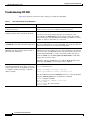
Troubleshooting IOS SLB IPC-150
Monitoring and Maintaining IOS SLB
IPC-149
IPC-151
Configuration Examples IPC-151
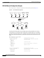
IOS SLB Network Configuration Example IPC-152
NAT Configuration Example IPC-153
HSRP Configuration Example IPC-155
IOS SLB Stateless Backup Configuration Example IPC-157
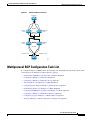
Configuring Mobile IP
IPC-159
Mobile IP Overview IPC-159
Why is Mobile IP Needed? IPC-159
Mobile IP Components IPC-160
How Mobile IP Works IPC-161
Agent Discovery IPC-161
Registration IPC-162
Routing IPC-162
Mobile IP Security IPC-163
MN-HA IPC-163
MN-FA IPC-164
FA-HA IPC-164
HA-HA IPC-164
Storing Security Associations IPC-164
Storing SAs on AAA IPC-165
Home Agent Redundancy IPC-165
HSRP Groups IPC-165
How HA Redundancy Works IPC-165
Prerequisites
IPC-166
Mobile IP Configuration Task List IPC-167
Enabling Home Agent Services IPC-167
Enabling Foreign Agent Services IPC-168
Configuring AAA in the Mobile IP Environment IPC-168
Configuring RADIUS in the Mobile IP Environment IPC-169
Configuring TACACS+ in the Mobile IP Environment IPC-169
Verifying Setup IPC-169
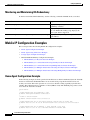
Monitoring and Maintaining Mobile IP IPC-170
Shutting Down Mobile IP IPC-170
Mobile IP HA Redundancy Configuration Task List
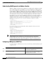
Enabling Mobile IP IPC-171
IPC-170
Cisco IOS IP Configuration Guide
xi
Contents
Enabling HSRP IPC-171
Configuring HSRP Group Attributes IPC-171
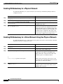
Enabling HA Redundancy for a Physical Network IPC-172
Enabling HA Redundancy for a Virtual Network Using One Physical Network IPC-172
Enabling HA Redundancy for a Virtual Network Using Multiple Physical Networks IPC-173
Enabling HA Redundancy for Multiple Virtual Networks Using One Physical Network IPC-174
Enabling HA Redundancy for Multiple Virtual Networks Using Multiple Physical Networks IPC-174
Verifying HA Redundancy IPC-175
Monitoring and Maintaining HA Redundancy IPC-176
Mobile IP Configuration Examples IPC-176
Home Agent Configuration Example IPC-176
Home Agent Using AAA Server Example IPC-177
Foreign Agent Configuration Example IPC-178
Mobile IP HA Redundancy Configuration Examples IPC-178
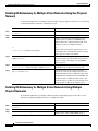
HA Redundancy for Physical Networks Example IPC-180
HA Redundancy for a Virtual Network Using One Physical Network Example IPC-182
HA Redundancy for a Virtual Network Using Multiple Physical Networks Example IPC-183
HA Redundancy for Multiple Virtual Networks Using One Physical Network Example IPC-186
HA Redundancy for Multiple Virtual Networks Using Multiple Physical Networks
Example IPC-189
IP ROUTING PROTOCOLS
Configuring On-Demand Routing IPC-195
On-Demand Routing Configuration Task List IPC-196
Enabling ODR IPC-196
Filtering ODR Information IPC-197
Redistributing ODR Information into the Dynamic Routing Protocol of the Hub
Reconfiguring CDP or ODR Timers IPC-197
Using ODR with Dialer Mappings IPC-198
Configuring Routing Information Protocol
IPC-199
RIP Configuration Task List IPC-200
Enabling RIP IPC-200
Allowing Unicast Updates for RIP IPC-201
Applying Offsets to Routing Metrics IPC-201
Adjusting Timers IPC-201
Specifying a RIP Version IPC-202
Enabling RIP Authentication IPC-203
RIP Route Summarization IPC-203
Cisco IOS IP Configuration Guide
xii
IPC-197
Contents
Restrictions to RIP Route Summarization IPC-205
Configuring Route Summarization on an Interface IPC-205
Verifying IP Route Summarization IPC-205
Disabling Automatic Route Summarization IPC-206
Running IGRP and RIP Concurrently IPC-206
Disabling the Validation of Source IP Addresses IPC-207
Enabling or Disabling Split Horizon IPC-207
Configuring Interpacket Delay IPC-208
Connecting RIP to a WAN IPC-208
RIP Configuration Examples IPC-209
Route Summarization Examples IPC-209
Example 1: Correct Configuration IPC-209
Example 2: Incorrect Configuration IPC-210
Split Horizon Examples IPC-210
Example 1 IPC-210
Example 2 IPC-210
Address Family Timers Example IPC-212
Configuring IGRP
IPC-213
The Cisco IGRP Implementation
IGRP Updates IPC-214
IPC-213
IGRP Configuration Task List IPC-214
Creating the IGRP Routing Process IPC-215
Applying Offsets to Routing Metrics IPC-215
Allowing Unicast Updates for IGRP IPC-215
Defining Unequal-Cost Load Balancing IPC-216
Controlling Traffic Distribution IPC-216
Adjusting the IGRP Metric Weights IPC-217
Adjusting Timers IPC-217
Disabling Holddown IPC-218
Enforcing a Maximum Network Diameter IPC-218
Validating Source IP Addresses IPC-218
Enabling or Disabling Split Horizon IPC-219
IGRP Configuration Examples IPC-219
IGRP Feasible Successor Relationship Example
Split Horizon Examples IPC-220
Configuring OSPF
IPC-220
IPC-223
The Cisco OSPF Implementation
OSPF Configuration Task List
IPC-223
IPC-224
Cisco IOS IP Configuration Guide
xiii
Contents
Enabling OSPF
IPC-225
Configuring OSPF Interface Parameters
IPC-225
Configuring OSPF over Different Physical Networks IPC-226
Configuring Your OSPF Network Type IPC-226
Configuring Point-to-Multipoint, Broadcast Networks IPC-227
Configuring OSPF for Nonbroadcast Networks IPC-227
Configuring OSPF Area Parameters
IPC-228
Configuring OSPF NSSA IPC-229
Implementation Considerations
IPC-230
Configuring Route Summarization Between OSPF Areas
IPC-230
Configuring Route Summarization When Redistributing Routes into OSPF
Creating Virtual Links
IPC-231
Generating a Default Route
IPC-231
Configuring Lookup of DNS Names
IPC-232
Forcing the Router ID Choice with a Loopback Interface
Controlling Default Metrics
IPC-232
IPC-232
Changing the OSPF Administrative Distances
IPC-233
Configuring OSPF on Simplex Ethernet Interfaces
Configuring Route Calculation Timers
IPC-233
IPC-233
Configuring OSPF over On-Demand Circuits IPC-234
Implementation Considerations IPC-235
Logging Neighbors Going Up or Down
IPC-235
Changing the LSA Group Pacing IPC-235
Original LSA Behavior IPC-236
LSA Group Pacing With Multiple Timers
Blocking OSPF LSA Flooding
Reducing LSA Flooding
IPC-236
IPC-237
IPC-238
Ignoring MOSPF LSA Packets
IPC-238
Displaying OSPF Update Packet Pacing
Monitoring and Maintaining OSPF
IPC-239
IPC-240
OSPF Configuration Examples IPC-241
OSPF Point-to-Multipoint Example IPC-241
OSPF Point-to-Multipoint, Broadcast Example IPC-243
OSPF Point-to-Multipoint, Nonbroadcast Example IPC-244
Variable-Length Subnet Masks Example IPC-244
OSPF Routing and Route Redistribution Examples IPC-245
Basic OSPF Configuration Examples IPC-245
Cisco IOS IP Configuration Guide
xiv
IPC-230
Contents
Basic OSPF Configuration Example for Internal Router, ABR, and ASBRs
Complex Internal Router, ABR, and ASBRs Example IPC-246
Complex OSPF Configuration for ABR Examples IPC-249
Route Map Examples IPC-250
Changing OSPF Administrative Distance Example IPC-252
OSPF over On-Demand Routing Example IPC-253
LSA Group Pacing Example IPC-255
Block LSA Flooding Example IPC-255
Ignore MOSPF LSA Packets Example IPC-255
Configuring EIGRP
IPC-246
IPC-257
The Cisco EIGRP Implementation
IPC-257
EIGRP Configuration Task List IPC-259
Enabling EIGRP IPC-259
Making the Transition from IGRP to EIGRP IPC-260
Logging EIGRP Neighbor Adjacency Changes IPC-260
Configuring the Percentage of Link Bandwidth Used IPC-260
Adjusting the EIGRP Metric Weights
IPC-260
Mismatched K Values IPC-261
The Goodbye Message IPC-262
Applying Offsets to Routing Metrics IPC-262
Disabling Route Summarization IPC-262
Configuring Summary Aggregate Addresses IPC-263
Configuring Floating Summary Routes IPC-263
Configuring EIGRP Route Authentication IPC-265
Configuring EIGRP Protocol-Independent Parameters IPC-266
Adjusting the Interval Between Hello Packets and the Hold Time
Disabling Split Horizon IPC-267
Configuring EIGRP Stub Routing IPC-268
Dual-Homed Remote Topology IPC-269
EIGRP Stub Routing Configuration Task List IPC-272
Configuring EIGRP Stub Routing IPC-272
Verifying EIGRP Stub Routing IPC-272
Monitoring and Maintaining EIGRP
IPC-266
IPC-272
EIGRP Configuration Examples IPC-273
Route Summarization Example IPC-273
Route Authentication Example IPC-275
Stub Routing Example IPC-276
Cisco IOS IP Configuration Guide
xv
Contents
Configuring Integrated IS-IS
IPC-277
IS-IS Configuration Task List IPC-277
Enabling IS-IS and Assigning Areas IPC-277
Enabling IP Routing for an Area on an Interface
IPC-279
IS-IS Interface Parameters Configuration Task List IPC-279
Configuring IS-IS Link-State Metrics IPC-280
Setting the Advertised Hello Interval IPC-280
Setting the Advertised CSNP Interval IPC-280
Setting the Retransmission Interval IPC-281
Setting the LSP Transmissions Interval IPC-281
Setting the Retransmission Throttle Interval IPC-281
Setting the Hello Multiplier IPC-282
Specifying Designated Router Election IPC-282
Specifying the Interface Circuit Type IPC-282
Assigning a Password for an Interface IPC-282
Limiting LSP Flooding IPC-283
Blocking Flooding on Specific Interfaces IPC-283
Configuring Mesh Groups IPC-283
Miscellaneous IS-IS Parameters Configuration Task List IPC-284
Generating a Default Route IPC-284
Specifying the System Type IPC-284
Configuring IS-IS Authentication Passwords IPC-285
Summarizing Address Ranges IPC-285
Setting the Overload Bit IPC-285
Changing the Routing Level for an Area IPC-286
Tuning LSP Interval and Lifetime IPC-286
Customizing IS-IS Throttling of LSP Generation, SPF Calculation, and PRC IPC-287
Partial Route Computation (PRC) IPC-287
Benefits of Throttling IS-IS LSP Generation, SPF Calculation, and PRC IPC-287
How Throttling of IS-IS LSP Generation, SPF Calculation, and PRC Works IPC-287
Modifying the Output of show Commands IPC-288
Monitoring IS-IS
IPC-289
IS-IS Configuration Examples IPC-289
Enabling IS-IS Configuration Example IPC-289
Multiarea IS-IS Configuration for CLNS Network Example
IS-IS Throttle Timers Example IPC-291
Configuring BGP
IPC-293
The Cisco BGP Implementation
Cisco IOS IP Configuration Guide
xvi
IPC-293
IPC-290
Contents
How BGP Selects Paths IPC-294
BGP Multipath Support IPC-295
Basic BGP Configuration Task List
IPC-295
Advanced BGP Configuration Task List
IPC-296
Configuring Basic BGP Features IPC-297
Enabling BGP Routing IPC-297
Configuring BGP Neighbors IPC-297
Managing Routing Policy Changes IPC-298
Resetting a Router Using BGP Dynamic Inbound Soft Reset IPC-299
Resetting a Router Using BGP Outbound Soft Reset IPC-300
Configuring BGP Soft Reset Using Stored Routing Policy Information IPC-300
Verifying BGP Soft Reset IPC-301
Configuring BGP Interactions with IGPs IPC-302
Configuring BGP Weights IPC-303
Disabling Autonomous System Path Comparison IPC-303
Configuring BGP Route Filtering by Neighbor IPC-304
Configuring BGP Filtering Using Prefix Lists IPC-304
How the System Filters Traffic by Prefix List IPC-305
Creating a Prefix List IPC-305
Configuring a Prefix List Entry IPC-306
Configuring How Sequence Numbers of Prefix List Entries Are Specified IPC-306
Deleting a Prefix List or Prefix List Entries IPC-307
Displaying Prefix Entries IPC-307
Clearing the Hit Count Table of Prefix List Entries IPC-308
Configuring BGP Path Filtering by Neighbor IPC-308
Disabling Next Hop Processing on BGP Updates IPC-308
Disabling Next Hop Processing Using a Specific Address IPC-309
Disabling Next Hop Processing Using a Route Map IPC-309
Configuring BGP Next Hop Propagation IPC-309
Configuring the BGP Version IPC-310
Configuring the MED Metric IPC-310
Configuring Advanced BGP Features IPC-311
Using Route Maps to Modify Updates IPC-311
Resetting eBGP Connections Immediately upon Link Failure IPC-311
Configuring Aggregate Addresses IPC-311
Disabling Automatic Summarization of Network Numbers IPC-312
Configuring BGP Community Filtering IPC-312
Specifying the Format for the Community IPC-314
Configuring BGP Conditional Advertisement IPC-314
Cisco IOS IP Configuration Guide
xvii
Contents
BGP Conditional Advertisement Configuration Task List IPC-315
Conditional Advertisement of a Set of Routes IPC-315
Verifying BGP Conditional Advertisement IPC-315
BGP Conditional Advertisement Troubleshooting Tips IPC-316
Configuring a Routing Domain Confederation IPC-316
Configuring a Route Reflector IPC-317
Configuring BGP Peer Groups IPC-320
Creating the Peer Group IPC-320
Assigning Options to the Peer Group IPC-321
Making Neighbors Members of the Peer Group IPC-324
Disabling a Peer or Peer Group IPC-324
Indicating Backdoor Routes IPC-325
Modifying Parameters While Updating the IP Routing Table IPC-325
Setting Administrative Distance IPC-325
Adjusting BGP Timers IPC-325
Changing the Default Local Preference Value IPC-326
Redistributing Network 0.0.0.0 IPC-326
Configuring the Router to Consider a Missing MED as Worst Path IPC-327
Selecting Path Based on MEDs from Other Autonomous Systems IPC-327
Configuring the Router to Use the MED to Choose a Path from Subautonomous System
Paths IPC-327
Configuring the Router to Use the MED to Choose a Path in a Confederation IPC-328
Configuring Route Dampening IPC-328
Minimizing Flapping IPC-328
Understanding Route Dampening Terms IPC-329
Enabling Route Dampening IPC-329
Monitoring and Maintaining BGP Route Dampening IPC-330
Monitoring and Maintaining BGP IPC-331
Clearing Caches, Tables, and Databases IPC-331
Displaying System and Network Statistics IPC-331
Logging Changes in Neighbor Status IPC-332
BGP Configuration Examples IPC-332
BGP Route Map Examples IPC-333
BGP Neighbor Configuration Examples IPC-336
BGP Prefix List Filtering Examples IPC-337
Route Filtering Configuration Example Using a Single Prefix List IPC-337
Route Filtering Configuration Example Specifying a Group of Prefixes IPC-338
Added or Deleted Prefix List Entries Examples IPC-339
BGP Soft Reset Examples IPC-339
Dynamic Inbound Soft Reset Example IPC-339
Cisco IOS IP Configuration Guide
xviii
Contents
Inbound Soft Reset Using Stored Information Example IPC-339
BGP Synchronization Examples IPC-340
BGP Path Filtering by Neighbor Examples IPC-340
BGP Aggregate Route Examples IPC-341
BGP Community with Route Maps Examples IPC-341
BGP Conditional Advertisement Configuration Examples IPC-343
BGP Confederation Examples IPC-344
BGP Peer Group Examples IPC-345
iBGP Peer Group Example IPC-345
eBGP Peer Group Example IPC-345
TCP MD5 Authentication for BGP Examples IPC-346
Configuring Multiprotocol BGP Extensions for IP Multicast
IPC-347
Multiprotocol BGP Configuration Task List IPC-349
Understanding NLRI Keywords and Address Families IPC-350
Configuring a Multiprotocol BGP Peer IPC-350
Configuring a Multiprotocol BGP Peer Group IPC-351
Advertising Routes into Multiprotocol BGP IPC-352
Configuring Route Maps for Multiprotocol BGP Prefixes IPC-353
Redistributing Prefixes into Multiprotocol BGP IPC-353
Configuring DVMRP Interoperability with Multiprotocol BGP IPC-354
Redistributing Multiprotocol BGP Routes into DVMRP IPC-354
Redistributing DVMRP Routes into Multiprotocol BGP IPC-355
Configuring a Multiprotocol BGP Route Reflector IPC-356
Configuring Aggregate Multiprotocol BGP Addresses IPC-356
Verifying Multiprotocol BGP Configuration and Operation IPC-357
Multiprotocol BGP Configuration Examples IPC-358
Multiprotocol BGP Peer Examples IPC-359
Multiprotocol BGP Peer Group Examples IPC-359
Multiprotocol BGP Network Advertisement Examples IPC-360
Multiprotocol BGP Route Map Examples IPC-360
Multiprotocol BGP Route Redistribute Examples IPC-360
Multiprotocol BGP Route Reflector Examples IPC-361
Aggregate Multiprotocol BGP Address Examples IPC-361
Configuring IP Routing Protocol-Independent Features
Protocol-Independent Feature Task List
Using Variable-Length Subnet Masks
Configuring Static Routes
IPC-364
Specifying Default Routes
IPC-365
IPC-363
IPC-363
IPC-364
Cisco IOS IP Configuration Guide
xix
Contents
Specifying a Default Network IPC-365
Understanding Gateway of Last Resort IPC-366
Changing the Maximum Number of Paths
IPC-366
Configuring Multi-Interface Load Splitting
IPC-366
Redistributing Routing Information IPC-367
Understanding Supported Metric Translations
IPC-369
Filtering Routing Information IPC-370
Preventing Routing Updates Through an Interface IPC-370
Configuring Default Passive Interfaces IPC-371
Controlling the Advertising of Routes in Routing Updates IPC-372
Controlling the Processing of Routing Updates IPC-372
Filtering Sources of Routing Information IPC-372
Enabling Policy Routing (PBR) IPC-373
Preverifying Next-Hop Availability IPC-375
Displaying Route-Map Policy Information IPC-376
Enabling Fast-Switched Policy Routing IPC-376
Enabling Local Policy Routing IPC-377
Managing Authentication Keys
IPC-377
Monitoring and Maintaining the IP Network IPC-378
Clearing Routes from the IP Routing Table IPC-378
Displaying System and Network Statistics IPC-378
IP Routing Protocol-Independent Configuration Examples IPC-379
Variable-Length Subnet Mask Example IPC-379
Overriding Static Routes with Dynamic Protocols Example IPC-380
Administrative Distance Examples IPC-380
Static Routing Redistribution Example IPC-381
IGRP Redistribution Example IPC-381
RIP and IGRP Redistribution Example IPC-382
EIGRP Redistribution Examples IPC-382
RIP and EIGRP Redistribution Examples IPC-383
Simple Redistribution Example IPC-383
Complex Redistribution Example IPC-383
OSPF Routing and Route Redistribution Examples IPC-384
Basic OSPF Configuration Examples IPC-384
Internal Router, ABR, and ASBRs Configuration Example IPC-385
Complex OSPF Configuration Example IPC-388
Default Metric Values Redistribution Example IPC-390
Policy Routing (Route Map) Examples IPC-390
Passive Interface Examples IPC-392
Cisco IOS IP Configuration Guide
xx
Contents
Default Passive Interface Example
Policy Routing Example IPC-393
Key Management Examples IPC-394
IPC-393
IP MULTICAST
Configuring IP Multicast Routing
IPC-399
The Cisco IP Multicast Routing Implementation
IGMP IPC-400
IGMP Versions IPC-401
PIM IPC-401
CGMP IPC-402
Basic IP Multicast Routing Configuration Task List
IPC-400
IPC-402
Advanced IP Multicast Routing Configuration Task List
Enabling IP Multicast Routing
IPC-402
IPC-403
Enabling PIM on an Interface IPC-403
Enabling Dense Mode IPC-403
Enabling Sparse Mode IPC-404
Enabling Sparse-Dense Mode IPC-404
Configuring PIM Dense Mode State Refresh
Configuring a Rendezvous Point IPC-406
IPC-405
Configuring Auto-RP IPC-406
Setting Up Auto-RP in a New Internetwork IPC-407
Adding Auto-RP to an Existing Sparse Mode Cloud IPC-407
Choosing a Default RP IPC-407
Announcing the RP and the Group Range It Serves IPC-407
Assigning the RP Mapping Agent IPC-407
Verifying the Group-to-RP Mapping IPC-408
Starting to Use IP Multicast IPC-408
Preventing Join Messages to False RPs IPC-408
Filtering Incoming RP Announcement Messages IPC-408
IGMP Features Configuration Task List IPC-409
Configuring a Router to Be a Member of a Group IPC-409
Controlling Access to IP Multicast Groups IPC-409
Changing the IGMP Version IPC-410
Modifying the IGMP Host-Query Message and Query Timeout Intervals
Routers That Run IGMP Version 1 IPC-410
Routers That Run IGMP Version 2 IPC-411
Configuring IGMP Version 3 IPC-411
IPC-410
Cisco IOS IP Configuration Guide
xxi
Contents
Restrictions IPC-412
Changing the IGMP Query Timeout IPC-413
Changing the Maximum Query Response Time IPC-413
Configuring the Router as a Statically Connected Member
Configuring IGMP Leave Latency IPC-414
Configuring the TTL Threshold
IPC-413
IPC-415
Disabling Fast Switching of IP Multicast
IPC-415
SAP Listener Support Configuration Task List IPC-415
Enabling SAP Listener Support IPC-415
Limiting How Long a SAP Cache Entry Exists IPC-416
Enabling the Functional Address for IP Multicast over Token Ring LANs
Configuring PIM Version 2 IPC-417
Prerequisites IPC-418
PIM Version 2 Configuration Task List IPC-418
Specifying the PIM Version IPC-419
Configuring PIM Version 2 Only IPC-419
Configuring PIM Sparse-Dense Mode IPC-419
Defining a PIM Sparse Mode Domain Border Interface
Configuring Candidate BSRs IPC-420
Configuring Candidate RPs IPC-420
Making the Transition to PIM Version 2 IPC-421
Deciding When to Configure a BSR IPC-421
Dense Mode IPC-422
Sparse Mode IPC-422
Monitoring the RP Mapping Information IPC-422
IPC-416
IPC-419
Advanced PIM Features Configuration Task List IPC-422
Understanding PIM Shared Tree and Source Tree (Shortest-Path Tree)
Understanding Reverse Path Forwarding IPC-424
Delaying the Use of PIM Shortest-Path Tree IPC-424
Assigning an RP to Multicast Groups IPC-425
Increasing Control over RPs IPC-425
Modifying the PIM Router Query Message Interval IPC-425
Understanding the PIM Registering Process IPC-426
PIM Version 1 Compatibility IPC-426
Limiting the Rate of PIM Register Messages IPC-427
Configuring the IP Source Address of Register Messages IPC-427
Enabling Proxy Registering IPC-427
Enabling PIM Nonbroadcast Multiaccess Mode IPC-428
Configuring an IP Multicast Static Route
Cisco IOS IP Configuration Guide
xxii
IPC-429
IPC-423
Contents
Controlling the Transmission Rate to a Multicast Group
IPC-430
Configuring RTP Header Compression IPC-430
Enabling RTP Header Compression on a Serial Interface IPC-432
Enabling RTP Header Compression with Frame Relay Encapsulation IPC-432
Changing the Number of Header Compression Connections IPC-432
Enabling Express RTP Header Compression IPC-433
Configuring IP Multicast over ATM Point-to-Multipoint Virtual Circuits IPC-434
Enabling IP Multicast over ATM Point-to-Multipoint VCs IPC-436
Limiting the Number of VCs IPC-436
Idling Policy IPC-437
How the Idling Policy Works IPC-437
Keeping VCs from Idling IPC-437
Configuring an IP Multicast Boundary
IPC-438
Configuring an Intermediate IP Multicast Helper
Storing IP Multicast Headers
Enabling CGMP
IPC-438
IPC-439
IPC-440
Configuring Stub IP Multicast Routing
IPC-440
Load Splitting IP Multicast Traffic Across Equal-Cost Paths Configuration Task List
Enabling Native Load Splitting IPC-442
Enabling Load Splitting Across Tunnels IPC-442
Configuring the Access Router IPC-443
Configuring the Router at the Opposite End of the Tunnel IPC-443
Configuring Both Routers to RPF IPC-444
Verifying the Load Splitting IPC-445
Monitoring and Maintaining IP Multicast Routing Configuration Task List
Clearing Caches, Tables, and Databases IPC-446
Displaying System and Network Statistics IPC-446
Using IP Multicast Heartbeat IPC-447
IPC-441
IPC-445
IP Multicast Configuration Examples IPC-448
PIM Dense Mode Example IPC-448
PIM Sparse Mode Example IPC-448
PIM Dense Mode State Refresh Example IPC-449
Functional Address for IP Multicast over Token Ring LAN Example IPC-449
PIM Version 2 Examples IPC-449
BSR Configuration Example IPC-449
Border Router Configuration Example IPC-450
RFC 2362 Interoperable Candidate RP Example IPC-450
RTP Header Compression Examples IPC-451
Express RTP Header Compression with PPP Encapsulation Example IPC-452
Cisco IOS IP Configuration Guide
xxiii
Contents
Express RTP Header Compression with Frame Relay Encapsulation Example
IP Multicast over ATM Point-to-Multipoint VC Example IPC-454
Administratively Scoped Boundary Example IPC-455
IP Multicast Helper Example IPC-455
Stub IP Multicast Example IPC-456
Load Splitting IP Multicast Traffic Across Equal-Cost Paths Example IPC-457
IP Multicast Heartbeat Example IPC-458
Configuring Source Specific Multicast
SSM Components Overview
IPC-459
IPC-459
How SSM Differs from Internet Standard Multicast
SSM IP Address Range
SSM Operations
IPC-460
IPC-460
IPC-460
IGMPv3 Host Signalling
IPC-461
IGMP v3lite Host Signalling
URD Host Signalling
IPC-461
IPC-462
Benefits IPC-464
IP Multicast Address Management Not Required IPC-464
Denial of Service Attacks from Unwanted Sources Inhibited
Easy to Install and Manage IPC-464
Ideal for Internet Broadcast Applications IPC-465
IPC-464
Restrictions IPC-465
Legacy Applications Within the SSM Range Restrictions IPC-465
IGMP v3lite and URD Require a Cisco IOS Last Hop Router IPC-465
Address Management Restrictions IPC-465
IGMP Snooping and CGMP Limitations IPC-466
URD Intercept URL Limitations IPC-466
State Maintenance Limitations IPC-466
HSIL Limitations IPC-466
SSM Configuration Task List IPC-467
Configuring SSM IPC-467
Monitoring SSM IPC-467
SSM Configuration Examples IPC-468
SSM with IGMPv3 Example IPC-468
SSM with IGMP v3lite and URD Example
SSM Filtering Example IPC-468
Configuring Bidirectional PIM
Bidir-PIM Overview
Cisco IOS IP Configuration Guide
xxiv
IPC-471
IPC-471
IPC-468
IPC-453
Contents
DF Election IPC-473
Bidirectional Group Tree Building
Packet Forwarding IPC-474
IPC-474
Bidir-PIM Configuration Task List IPC-474
Prerequisites IPC-474
Configuring Bidir-PIM IPC-475
Verifying Bidirectional Groups IPC-475
Monitoring and Maintaining Bidir-PIM IPC-476
Bidir-PIM Configuration Example
IPC-476
Configuring Multicast Source Discovery Protocol
How MSDP Works
Benefits
IPC-477
IPC-477
IPC-479
Prerequisites
IPC-479
MSDP Configuration Task List IPC-479
Configuring an MSDP Peer IPC-480
Caching SA State IPC-480
Requesting Source Information from an MSDP Peer IPC-481
Controlling Source Information That Your Router Originates IPC-481
Redistributing Sources IPC-481
Filtering SA Request Messages IPC-482
Controlling Source Information That Your Router Forwards IPC-482
Using an MSDP Filter IPC-482
Using TTL to Limit the Multicast Data Sent in SA Messages IPC-483
Controlling Source Information That Your Router Receives IPC-483
Configuring a Default MSDP Peer IPC-484
Configuring an MSDP Mesh Group IPC-485
Shutting Down an MSDP Peer IPC-485
Including a Bordering PIM Dense Mode Region in MSDP IPC-486
Configuring an Originating Address Other Than the RP Address IPC-486
Monitoring and Maintaining MSDP
IPC-487
MSDP Configuration Examples IPC-488
Default MSDP Peer IPC-488
Logical RP IPC-488
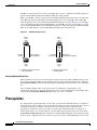
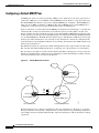
Configuring PGM Host and Router Assist
PGM Overview
IPC-493
IPC-493
PGM Host Configuration Task List
Prerequisites IPC-495
IPC-495
Cisco IOS IP Configuration Guide
xxv
Contents
Enabling PGM Host IPC-495
Enabling PGM Host with a Virtual Host Interface IPC-496
Enabling PGM Host with a Physical Interface IPC-496
Verifying PGM Host Configuration IPC-496
PGM Router Assist Configuration Task List IPC-498
Prerequisites IPC-498
Enabling PGM Router Assist IPC-498
Enabling PGM Router Assist with a Virtual Host Interface IPC-499
Enabling PGM Router Assist with a Physical Interface IPC-499
Monitoring and Maintaining PGM Host and Router Assist IPC-499
Monitoring and Maintaining PGM Host IPC-499
Monitoring and Maintaining PGM Router Assist IPC-500
PGM Host and Router Assist Configuration Examples IPC-500
PGM Host with a Virtual Interface Example IPC-501
PGM Host with a Physical Interface Example IPC-501
PGM Router Assist with a Virtual Interface Example IPC-502
PGM Router Assist with a Physical Interface Example IPC-502
Configuring Unidirectional Link Routing
IPC-505
UDLR Overview IPC-505
UDLR Tunnel IPC-506
IGMP UDLR IPC-506
IGMP Proxy IPC-507
UDLR Tunnel Configuration Task List IPC-508
Prerequisite IPC-508
Configuring UDLR Tunnel IPC-508
IGMP UDLR Configuration Task List IPC-510
Prerequisites IPC-510
Configuring the IGMP UDL IPC-510
Changing the Distance for the Default RPF Interface
Monitoring IGMP UDLR IPC-511
IGMP Proxy Configuration Task List IPC-511
Prerequisites IPC-512
Configuring IGMP Proxy IPC-512
Verifying IGMP Proxy IPC-512
UDLR Configuration Examples IPC-513
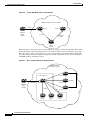
UDLR Tunnel Example IPC-513
IGMP UDLR Example IPC-514
IGMP Proxy Example IPC-516
Cisco IOS IP Configuration Guide
xxvi
IPC-511
Contents
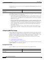
Integrated UDLR Tunnel, IGMP UDLR, and IGMP Proxy Example
Using IP Multicast Tools
IPC-521
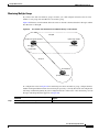
Multicast Routing Monitor Overview
Benefits IPC-521
Restrictions IPC-522
IPC-521
MRM Configuration Task List IPC-522
Configuring a Test Sender and Test Receiver
Monitoring Multiple Groups IPC-523
Configuring a Manager IPC-524
Conducting an MRM Test IPC-524
Monitoring IP Multicast Routing
MRM Configuration Example
IPC-522
IPC-525
Monitoring and Maintaining MRM
IPC-525
IPC-526
Configuring Router-Port Group Management Protocol
IP Multicast Routing Overview
RGMP Overview
IPC-518
IPC-527
IPC-527
IPC-528
RGMP Configuration Task List IPC-531
Prerequisites IPC-531
Enabling RGMP IPC-532
Verifying RGMP Configuration IPC-532
Monitoring and Maintaining RGMP
RGMP Configuration Example
IPC-533
IPC-534
Configuring DVMRP Interoperability
IPC-537
Basic DVMRP Interoperability Configuration Task List IPC-537
Configuring DVMRP Interoperability IPC-538
Responding to mrinfo Requests IPC-538
Configuring a DVMRP Tunnel IPC-539
Advertising Network 0.0.0.0 to DVMRP Neighbors IPC-540
Advanced DVMRP Interoperability Configuration Task List IPC-540
Enabling DVMRP Unicast Routing IPC-540
Limiting the Number of DVMRP Routes Advertised IPC-541
Changing the DVMRP Route Threshold IPC-541
Configuring a DVMRP Summary Address IPC-541
Disabling DVMRP Automatic summarization IPC-542
Adding a Metric Offset to the DVMRP Route IPC-542
Rejecting a DVMRP Nonpruning Neighbor IPC-543
Configuring a Delay Between DVRMP Reports IPC-544
Cisco IOS IP Configuration Guide
xxvii
Contents
Monitoring and Maintaining DVMRP
IPC-545
DVMRP Configuration Examples IPC-545
DVMRP Interoperability Example IPC-545
DVMRP Tunnel Example IPC-545
INDEX
Cisco IOS IP Configuration Guide
xxviii
About Cisco IOS Software Documentation
This chapter discusses the objectives, audience, organization, and conventions of Cisco IOS software
documentation. It also provides sources for obtaining documentation from Cisco Systems.
Documentation Objectives
Cisco IOS software documentation describes the tasks and commands necessary to configure and
maintain Cisco networking devices.
Audience
The Cisco IOS software documentation set is intended primarily for users who configure and maintain
Cisco networking devices (such as routers and switches) but who may not be familiar with the tasks,
the relationship between tasks, or the Cisco IOS software commands necessary to perform particular
tasks. The Cisco IOS software documentation set is also intended for those users experienced with
Cisco IOS software who need to know about new features, new configuration options, and new software
characteristics in the current Cisco IOS software release.
Documentation Organization
The Cisco IOS software documentation set consists of documentation modules and master indexes. In
addition to the main documentation set, there are supporting documents and resources.
Documentation Modules
The Cisco IOS documentation modules consist of configuration guides and corresponding command
reference publications. Chapters in a configuration guide describe protocols, configuration tasks, and
Cisco IOS software functionality and contain comprehensive configuration examples. Chapters in a
command reference publication provide complete Cisco IOS command syntax information. Use each
configuration guide in conjunction with its corresponding command reference publication.
Cisco IOS IP Configuration Guide
xxix
About Cisco IOS Software Documentation
Documentation Organization
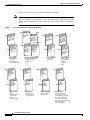
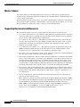
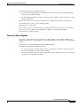
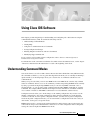
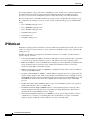
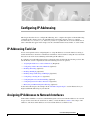
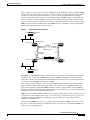
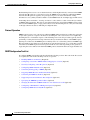
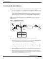
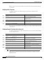
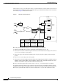
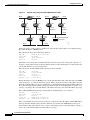
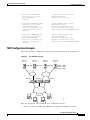
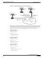
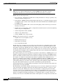
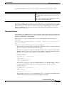
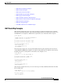
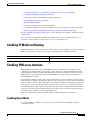
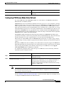
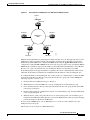
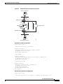
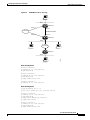
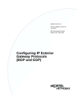
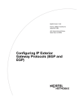
Figure 1 shows the Cisco IOS software documentation modules.
Note
Figure 1
The abbreviations (for example, FC and FR) next to the book icons are page designators,
which are defined in a key in the index of each document to help you with navigation. The
bullets under each module list the major technology areas discussed in the corresponding
books.
Cisco IOS Software Documentation Modules
IPC
FC
Cisco IOS
Configuration
Fundamentals
Configuration
Guide
Cisco IOS
Configuration
Fundamentals
Command
Reference
FR
IP2R
Module FC/FR:
• Cisco IOS User
Interfaces
• File Management
• System Management
Cisco IOS
Wide-Area
Networking
Command
Reference
WR
Module WC/WR:
• ATM
• Broadband Access
• Frame Relay
• SMDS
• X.25 and LAPB
Cisco IOS
IP Command
Reference,
Volume 1 of 3:
Addressing
and Services
Cisco IOS
IP Command
Reference,
Volume 2 of 3:
Routing
Protocols
P2C
IP3R
Cisco IOS
IP Command
Reference,
Volume 3 of 3:
Multicast
Cisco IOS
Interface
Configuration
Guide
IR
Cisco IOS
Interface
Command
Reference
Module IC/IR:
• LAN Interfaces
• Serial Interfaces
• Logical Interfaces
P3C
Cisco IOS
AppleTalk and
Novell IPX
Configuration
Guide
P2R
Module IPC/IP1R/IP2R/IP3R:
• IP Addressing and Services
• IP Routing Protocols
• IP Multicast
IC
Cisco IOS
Wide-Area
Networking
Configuration
Guide
IP1R
Cisco IOS
AppleTalk and
Novell IPX
Command
Reference
P3R
Module P2C/P2R:
• AppleTalk
• Novell IPX
MWC
Cisco IOS
Mobile
Wireless
Configuration
Guide
MWR
Cisco IOS
Mobile
Wireless
Command
Reference
Module MWC/MWR:
• General Packet
Radio Service
Cisco IOS
Apollo Domain,
Banyan VINES,
DECnet, ISO
CLNS, and XNS
Configuration
Guide
SC
Cisco IOS
Apollo Domain,
Banyan VINES,
DECnet, ISO
CLNS, and XNS
Command
Reference
Module P3C/P3R:
• Apollo Domain
• Banyan VINES
• DECnet
• ISO CLNS
• XNS
Cisco IOS
Security
Configuration
Guide
SR
Cisco IOS
Security
Command
Reference
Module SC/SR:
• AAA Security Services
• Security Server Protocols
• Traffic Filtering and Firewalls
• IP Security and Encryption
• Passwords and Privileges
• Neighbor Router Authentication
• IP Security Options
• Supported AV Pairs
47953
WC
Cisco IOS
IP
Configuration
Guide
Cisco IOS IP Configuration Guide
xxx
About Cisco IOS Software Documentation
Documentation Organization
Cisco IOS
Dial
Technologies
Configuration
Guide
TC
BC
Cisco IOS
Terminal
Services
Configuration
Guide
Cisco IOS
Bridging and
IBM Networking
Configuration
Guide
B2R
B1R
DR
Cisco IOS
Dial
Technologies
Command
Reference
TR
Module DC/DR:
• Preparing for Dial Access
• Modem and Dial Shelf Configuration
and Management
• ISDN Configuration
• Signalling Configuration
• Dial-on-Demand Routing
Configuration
• Dial-Backup Configuration
• Dial-Related Addressing Services
• Virtual Templates, Profiles, and
Networks
• PPP Configuration
• Callback and Bandwidth Allocation
Configuration
• Dial Access Specialized Features
• Dial Access Scenarios
VC
Cisco IOS
Voice, Video,
and Fax
Configuration
Guide
VR
Cisco IOS
Voice, Video,
and Fax
Command
Reference
Module VC/VR:
• Voice over IP
• Call Control Signalling
• Voice over
Frame Relay
• Voice over ATM
• Telephony Applications
• Trunk Management
• Fax, Video, and
Modem Support
Cisco IOS
Terminal
Services
Command
Reference
Module TC/TR:
• ARA
• LAT
• NASI
• Telnet
• TN3270
• XRemote
• X.28 PAD
• Protocol Translation
QC
Cisco IOS
Quality of
Service
Solutions
Configuration
Guide
QR
Cisco IOS
Quality of
Service
Solutions
Command
Reference
Module QC/QR:
• Packet Classification
• Congestion Management
• Congestion Avoidance
• Policing and Shaping
• Signalling
• Link Efficiency
Mechanisms
Cisco IOS
Bridging
and IBM
Networking
Command
Reference,
Volume 1 of 2
Cisco IOS
Bridging
and IBM
Networking
Command
Reference,
Volume 2 of 2
Module BC/B1R:
• Transparent
Bridging
• SRB
• Token Ring
Inter-Switch Link
• Token Ring Route
Switch Module
• RSRB
• DLSw+
• Serial Tunnel and
Block Serial Tunnel
• LLC2 and SDLC
• IBM Network
Media Translation
• SNA Frame Relay
Access
• NCIA Client/Server
• Airline Product Set
XC
Module BC/B2R:
• DSPU and SNA
Service Point
• SNA Switching
Services
• Cisco Transaction
Connection
• Cisco Mainframe
Channel Connection
• CLAW and TCP/IP
Offload
• CSNA, CMPC,
and CMPC+
• TN3270 Server
Cisco IOS
Switching
Services
Configuration
Guide
XR
Cisco IOS
Switching
Services
Command
Reference
Module XC/XR:
• Cisco IOS
Switching Paths
• NetFlow Switching
• Multiprotocol Label Switching
• Multilayer Switching
• Multicast Distributed Switching
• Virtual LANs
• LAN Emulation
47954
DC
Cisco IOS IP Configuration Guide
xxxi
About Cisco IOS Software Documentation
Documentation Organization
Master Indexes
Two master indexes provide indexing information for the Cisco IOS software documentation set:
an index for the configuration guides and an index for the command references. Individual books also
contain a book-specific index.
The master indexes provide a quick way for you to find a command when you know the command name
but not which module contains the command. When you use the online master indexes, you can click
the page number for an index entry and go to that page in the online document.
Supporting Documents and Resources
The following documents and resources support the Cisco IOS software documentation set:
•
Cisco IOS Command Summary (two volumes)—This publication explains the function and syntax
of the Cisco IOS software commands. For more information about defaults and usage guidelines,
refer to the Cisco IOS command reference publications.
•
Cisco IOS System Error Messages—This publication lists and describes Cisco IOS system error
messages. Not all system error messages indicate problems with your system. Some are purely
informational, and others may help diagnose problems with communications lines, internal
hardware, or the system software.
•
Cisco IOS Debug Command Reference—This publication contains an alphabetical listing of the
debug commands and their descriptions. Documentation for each command includes a brief
description of its use, command syntax, usage guidelines, and sample output.
•
Dictionary of Internetworking Terms and Acronyms—This Cisco publication compiles and defines
the terms and acronyms used in the internetworking industry.
•
New feature documentation—The Cisco IOS software documentation set documents the mainline
release of Cisco IOS software (for example, Cisco IOS Release 12.2). New software features are
introduced in early deployment releases (for example, the Cisco IOS “T” release train for 12.2,
12.2(x)T). Documentation for these new features can be found in standalone documents called
“feature modules.” Feature module documentation describes new Cisco IOS software and hardware
networking functionality and is available on Cisco.com and the Documentation CD-ROM.
•
Release notes—This documentation describes system requirements, provides information about
new and changed features, and includes other useful information about specific software releases.
See the section “Using Software Release Notes” in the chapter “Using Cisco IOS Software” for
more information.
•
Caveats documentation—This documentation provides information about Cisco IOS software
defects in specific software releases.
•
RFCs—RFCs are standards documents maintained by the Internet Engineering Task Force (IETF).
Cisco IOS software documentation references supported RFCs when applicable. The full text of
referenced RFCs may be obtained on the World Wide Web at http://www.rfc-editor.org/.
•
MIBs—MIBs are used for network monitoring. For lists of supported MIBs by platform and
release, and to download MIB files, see the Cisco MIB website on Cisco.com at
http://www.cisco.com/public/sw-center/netmgmt/cmtk/mibs.shtml.
Cisco IOS IP Configuration Guide
xxxii
About Cisco IOS Software Documentation
New and Changed Information
New and Changed Information
The following is new or changed information since the last release of the Cisco IOS IP and IP routing
publications:
•
The title of the Cisco IOS IP and IP Routing Configuration Guide has been changed to Cisco IOS
IP Configuration Guide.
•
The Cisco IOS IP and IP Routing Command Reference has been divided into three separate
publications with the following titles:
– Cisco IOS IP Command Reference, Volume 1 of 3: Addressing and Services
– Cisco IOS IP Command Reference, Volume 2 of 3: Routing Protocols
– Cisco IOS IP Command Reference, Volume 3 of 3: Multicast
•
The following new chapters were added to the Cisco IOS IP Configuration Guide:
– “Configuring Server Load Balancing”
– “Configuring Source Specific Multicast”
– “Configuring Bidirectional PIM”
– “Configuring Router-Port Group Management Protocol”
•
The following new chapter was added to the Cisco IOS IP Command Reference, Volume 1 of 3:
Addressing and Services:
– “Server Load Balancing Commands”
Document Conventions
Within Cisco IOS software documentation, the term router is generally used to refer to a variety of Cisco
products (for example, routers, access servers, and switches). Routers, access servers, and other
networking devices that support Cisco IOS software are shown interchangeably within examples. These
products are used only for illustrative purposes; that is, an example that shows one product does not
necessarily indicate that other products are not supported.
The Cisco IOS documentation set uses the following conventions:
Convention
Description
^ or Ctrl
The ^ and Ctrl symbols represent the Control key. For example, the key combination ^D or Ctrl-D
means hold down the Control key while you press the D key. Keys are indicated in capital letters but
are not case sensitive.
string
A string is a nonquoted set of characters shown in italics. For example, when setting an SNMP
community string to public, do not use quotation marks around the string or the string will include the
quotation marks.
Cisco IOS IP Configuration Guide
xxxiii
About Cisco IOS Software Documentation
Document Conventions
Command syntax descriptions use the following conventions:
Convention
Description
boldface
Boldface text indicates commands and keywords that you enter literally as shown.
italics
Italic text indicates arguments for which you supply values.
[x]
Square brackets enclose an optional element (keyword or argument).
|
A vertical line indicates a choice within an optional or required set of keywords or arguments.
[x | y]
Square brackets enclosing keywords or arguments separated by a vertical line indicate an optional
choice.
{x | y}
Braces enclosing keywords or arguments separated by a vertical line indicate a required choice.
Nested sets of square brackets or braces indicate optional or required choices within optional or
required elements. For example:
Convention
Description
[x {y | z}]
Braces and a vertical line within square brackets indicate a required choice within an optional element.
Examples use the following conventions:
Convention
Description
screen
Examples of information displayed on the screen are set in Courier font.
boldface screen
Examples of text that you must enter are set in Courier bold font.
<
Angle brackets enclose text that is not printed to the screen, such as passwords.
>
!
[
An exclamation point at the beginning of a line indicates a comment line. (Exclamation points are also
displayed by the Cisco IOS software for certain processes.)
]
Square brackets enclose default responses to system prompts.
The following conventions are used to attract the attention of the reader:
Caution
Note
Timesaver
Means reader be careful. In this situation, you might do something that could result in
equipment damage or loss of data.
Means reader take note. Notes contain helpful suggestions or references to materials not
contained in this manual.
Means the described action saves time. You can save time by performing the action
described in the paragraph.
Cisco IOS IP Configuration Guide
xxxiv
About Cisco IOS Software Documentation
Obtaining Documentation
Obtaining Documentation
The following sections provide sources for obtaining documentation from Cisco Systems.
World Wide Web
The most current Cisco documentation is available on the World Wide Web at the following website:
http://www.cisco.com
Translated documentation is available at the following website:
http://www.cisco.com/public/countries_languages.html
Documentation CD-ROM
Cisco documentation and additional literature are available in a CD-ROM package, which ships
with your product. The Documentation CD-ROM is updated monthly and may be more current than
printed documentation. The CD-ROM package is available as a single unit or through an
annual subscription.
Ordering Documentation
Cisco documentation can be ordered in the following ways:
•
Registered Cisco Direct Customers can order Cisco product documentation from the Networking
Products MarketPlace:
http://www.cisco.com/cgi-bin/order/order_root.pl
•
Registered Cisco.com users can order the Documentation CD-ROM through the online
Subscription Store:
http://www.cisco.com/go/subscription
•
Nonregistered Cisco.com users can order documentation through a local account representative by
calling Cisco corporate headquarters (California, USA) at 408 526-7208 or, in North America, by
calling 800 553-NETS(6387).
Documentation Feedback
If you are reading Cisco product documentation on the World Wide Web, you can submit technical
comments electronically. Click Feedback in the toolbar and select Documentation. After you complete
the form, click Submit to send it to Cisco.
You can e-mail your comments to [email protected].
Cisco IOS IP Configuration Guide
xxxv
About Cisco IOS Software Documentation
Obtaining Technical Assistance
To submit your comments by mail, use the response card behind the front cover of your document, or
write to the following address:
Cisco Systems, Inc.
Document Resource Connection
170 West Tasman Drive
San Jose, CA 95134-9883
We appreciate your comments.
Obtaining Technical Assistance
Cisco provides Cisco.com as a starting point for all technical assistance. Customers and partners can
obtain documentation, troubleshooting tips, and sample configurations from online tools. For
Cisco.com registered users, additional troubleshooting tools are available from the TAC website.
Cisco.com
Cisco.com is the foundation of a suite of interactive, networked services that provides immediate, open
access to Cisco information and resources at anytime, from anywhere in the world. This highly
integrated Internet application is a powerful, easy-to-use tool for doing business with Cisco.
Cisco.com provides a broad range of features and services to help customers and partners streamline
business processes and improve productivity. Through Cisco.com, you can find information about Cisco
and our networking solutions, services, and programs. In addition, you can resolve technical issues with
online technical support, download and test software packages, and order Cisco learning materials and
merchandise. Valuable online skill assessment, training, and certification programs are also available.
Customers and partners can self-register on Cisco.com to obtain additional personalized information
and services. Registered users can order products, check on the status of an order, access technical
support, and view benefits specific to their relationships with Cisco.
To access Cisco.com, go to the following website:
http://www.cisco.com
Technical Assistance Center
The Cisco TAC website is available to all customers who need technical assistance with a Cisco product
or technology that is under warranty or covered by a maintenance contract.
Contacting TAC by Using the Cisco TAC Website
If you have a priority level 3 (P3) or priority level 4 (P4) problem, contact TAC by going to the TAC
website:
http://www.cisco.com/tac
Cisco IOS IP Configuration Guide
xxxvi
About Cisco IOS Software Documentation
Obtaining Technical Assistance
P3 and P4 level problems are defined as follows:
•
P3—Your network performance is degraded. Network functionality is noticeably impaired, but
most business operations continue.
•
P4—You need information or assistance on Cisco product capabilities, product installation, or basic
product configuration.
In each of the above cases, use the Cisco TAC website to quickly find answers to your questions.
To register for Cisco.com, go to the following website:
http://www.cisco.com/register/
If you cannot resolve your technical issue by using the TAC online resources, Cisco.com registered
users can open a case online by using the TAC Case Open tool at the following website:
http://www.cisco.com/tac/caseopen
Contacting TAC by Telephone
If you have a priority level 1 (P1) or priority level 2 (P2) problem, contact TAC by telephone and
immediately open a case. To obtain a directory of toll-free numbers for your country, go to the following
website:
http://www.cisco.com/warp/public/687/Directory/DirTAC.shtml
P1 and P2 level problems are defined as follows:
•
P1—Your production network is down, causing a critical impact to business operations if service
is not restored quickly. No workaround is available.
•
P2—Your production network is severely degraded, affecting significant aspects of your business
operations. No workaround is available.
Cisco IOS IP Configuration Guide
xxxvii
About Cisco IOS Software Documentation
Obtaining Technical Assistance
Cisco IOS IP Configuration Guide
xxxviii
Using Cisco IOS Software
This chapter provides helpful tips for understanding and configuring Cisco IOS software using the
command-line interface (CLI). It contains the following sections:
•
Understanding Command Modes
•
Getting Help
•
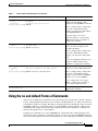
Using the no and default Forms of Commands
•
Saving Configuration Changes
•
Filtering Output from the show and more Commands
•
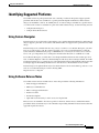
Identifying Supported Platforms
For an overview of Cisco IOS software configuration, refer to the Cisco IOS Configuration
Fundamentals Configuration Guide.
For information on the conventions used in the Cisco IOS software documentation set, see the chapter
“About Cisco IOS Software Documentation” located at the beginning of this book.
Understanding Command Modes
You use the CLI to access Cisco IOS software. Because the CLI is divided into many different modes,
the commands available to you at any given time depend on the mode you are currently in. Entering a
question mark (?) at the CLI prompt allows you to obtain a list of commands available for each
command mode.
When you log in to the CLI, you are in user EXEC mode. User EXEC mode contains only a limited
subset of commands. To have access to all commands, you must enter privileged EXEC mode, normally
by using a password. From privileged EXEC mode you can issue any EXEC command—user or
privileged mode—or you can enter global configuration mode. Most EXEC commands are one-time
commands. For example, show commands show important status information, and clear commands
clear counters or interfaces. The EXEC commands are not saved when the software reboots.
Configuration modes allow you to make changes to the running configuration. If you later save the
running configuration to the startup configuration, these changed commands are stored when the
software is rebooted. To enter specific configuration modes, you must start at global configuration
mode. From global configuration mode, you can enter interface configuration mode and a variety of
other modes, such as protocol-specific modes.
ROM monitor mode is a separate mode used when the Cisco IOS software cannot load properly. If a
valid software image is not found when the software boots or if the configuration file is corrupted at
startup, the software might enter ROM monitor mode.
Cisco IOS IP Configuration Guide
xxxix
Using Cisco IOS Software
Getting Help
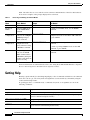
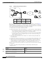
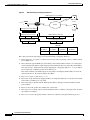
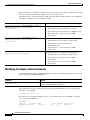
Table 1 describes how to access and exit various common command modes of the Cisco IOS software.
It also shows examples of the prompts displayed for each mode.
Table 1
Accessing and Exiting Command Modes
Command
Mode
Access Method
Prompt
Exit Method
User EXEC
Log in.
Router>
Use the logout command.
Privileged
EXEC
From user EXEC mode,
use the enable EXEC
command.
Router#
To return to user EXEC mode, use the disable
command.
Global
configuration
From privileged EXEC
mode, use the configure
terminal privileged
EXEC command.
Router(config)#
To return to privileged EXEC mode from global
configuration mode, use the exit or end command,
or press Ctrl-Z.
Interface
configuration
Router(config-if)#
From global
configuration mode,
specify an interface using
an interface command.
To return to global configuration mode, use the exit
command.
>
From privileged EXEC
mode, use the reload
EXEC command. Press
the Break key during the
first 60 seconds while the
system is booting.
To exit ROM monitor mode, use the continue
command.
ROM monitor
To return to privileged EXEC mode, use the end
command, or press Ctrl-Z.
For more information on command modes, refer to the “Using the Command-Line Interface” chapter in
the Cisco IOS Configuration Fundamentals Configuration Guide.
Getting Help
Entering a question mark (?) at the CLI prompt displays a list of commands available for each command
mode. You can also get a list of keywords and arguments associated with any command by using the
context-sensitive help feature.
To get help specific to a command mode, a command, a keyword, or an argument, use one of the
following commands:
Command
Purpose
help
Provides a brief description of the help system in any command mode.
abbreviated-command-entry?
Provides a list of commands that begin with a particular character string. (No space
between command and question mark.)
abbreviated-command-entry<Tab>
Completes a partial command name.
?
Lists all commands available for a particular command mode.
command ?
Lists the keywords or arguments that you must enter next on the command line.
(Space between command and question mark.)
Cisco IOS IP Configuration Guide
xl
Using Cisco IOS Software
Getting Help
Example: How to Find Command Options
This section provides an example of how to display syntax for a command. The syntax can consist of
optional or required keywords and arguments. To display keywords and arguments for a command, enter
a question mark (?) at the configuration prompt or after entering part of a command followed by a space.
The Cisco IOS software displays a list and brief description of available keywords and arguments. For
example, if you were in global configuration mode and wanted to see all the keywords or arguments for
the arap command, you would type arap ?.
The <cr> symbol in command help output stands for “carriage return.” On older keyboards, the carriage
return key is the Return key. On most modern keyboards, the carriage return key is the Enter key. The
<cr> symbol at the end of command help output indicates that you have the option to press Enter to
complete the command and that the arguments and keywords in the list preceding the <cr> symbol are
optional. The <cr> symbol by itself indicates that no more arguments or keywords are available and that
you must press Enter to complete the command.
Table 2 shows examples of how you can use the question mark (?) to assist you in entering commands.
The table steps you through configuring an IP address on a serial interface on a Cisco 7206 router that
is running Cisco IOS Release 12.0(3).
Table 2
How to Find Command Options
Command
Comment
Router> enable
Password: <password>
Router#
Enter the enable command and
password to access privileged EXEC
commands. You are in privileged
EXEC mode when the prompt changes
to Router#.
Router# configure terminal
Enter configuration commands, one per line. End with CNTL/Z.
Router(config)#
Enter the configure terminal
privileged EXEC command to enter
global configuration mode. You are in
global configuration mode when the
prompt changes to Router(config)#.
Router(config)# interface serial ?
<0-6>
Serial interface number
Router(config)# interface serial 4 ?
/
Router(config)# interface serial 4/ ?
<0-3>
Serial interface number
Router(config)# interface serial 4/0
Router(config-if)#
Enter interface configuration mode by
specifying the serial interface that you
want to configure using the interface
serial global configuration command.
Enter ? to display what you must enter
next on the command line. In this
example, you must enter the serial
interface slot number and port number,
separated by a forward slash.
You are in interface configuration mode
when the prompt changes to
Router(config-if)#.
Cisco IOS IP Configuration Guide
xli
Using Cisco IOS Software
Getting Help
Table 2
How to Find Command Options (continued)
Command
Comment
Router(config-if)# ?
Interface configuration commands:
.
.
.
ip
Interface Internet Protocol config commands
keepalive
Enable keepalive
lan-name
LAN Name command
llc2
LLC2 Interface Subcommands
load-interval
Specify interval for load calculation for an
interface
locaddr-priority
Assign a priority group
logging
Configure logging for interface
loopback
Configure internal loopback on an interface
mac-address
Manually set interface MAC address
mls
mls router sub/interface commands
mpoa
MPOA interface configuration commands
mtu
Set the interface Maximum Transmission Unit (MTU)
netbios
Use a defined NETBIOS access list or enable
name-caching
no
Negate a command or set its defaults
nrzi-encoding
Enable use of NRZI encoding
ntp
Configure NTP
.
.
.
Router(config-if)#
Enter ? to display a list of all the
interface configuration commands
available for the serial interface. This
example shows only some of the
available interface configuration
commands.
Router(config-if)# ip ?
Interface IP configuration subcommands:
access-group
Specify access control for packets
accounting
Enable IP accounting on this interface
address
Set the IP address of an interface
authentication
authentication subcommands
bandwidth-percent
Set EIGRP bandwidth limit
broadcast-address
Set the broadcast address of an interface
cgmp
Enable/disable CGMP
directed-broadcast Enable forwarding of directed broadcasts
dvmrp
DVMRP interface commands
hello-interval
Configures IP-EIGRP hello interval
helper-address
Specify a destination address for UDP broadcasts
hold-time
Configures IP-EIGRP hold time
.
.
.
Router(config-if)# ip
Enter the command that you want to
configure for the interface. This
example uses the ip command.
Cisco IOS IP Configuration Guide
xlii
Enter ? to display what you must enter
next on the command line. This
example shows only some of the
available interface IP configuration
commands.
Using Cisco IOS Software
Using the no and default Forms of Commands
Table 2
How to Find Command Options (continued)
Command
Comment
Router(config-if)# ip address ?
A.B.C.D
IP address
negotiated
IP Address negotiated over PPP
Router(config-if)# ip address
Enter the command that you want to
configure for the interface. This
example uses the ip address command.
Enter ? to display what you must enter
next on the command line. In this
example, you must enter an IP address
or the negotiated keyword.
A carriage return (<cr>) is not
displayed; therefore, you must enter
additional keywords or arguments to
complete the command.
Router(config-if)# ip address 172.16.0.1 ?
A.B.C.D
IP subnet mask
Router(config-if)# ip address 172.16.0.1
Enter the keyword or argument you
want to use. This example uses the
172.16.0.1 IP address.
Enter ? to display what you must enter
next on the command line. In this
example, you must enter an IP subnet
mask.
A <cr> is not displayed; therefore, you
must enter additional keywords or
arguments to complete the command.
Router(config-if)# ip address 172.16.0.1 255.255.255.0 ?
secondary
Make this IP address a secondary address
<cr>
Router(config-if)# ip address 172.16.0.1 255.255.255.0
Enter the IP subnet mask. This example
uses the 255.255.255.0 IP subnet mask.
Enter ? to display what you must enter
next on the command line. In this
example, you can enter the secondary
keyword, or you can press Enter.
A <cr> is displayed; you can press
Enter to complete the command, or
you can enter another keyword.
Router(config-if)# ip address 172.16.0.1 255.255.255.0
Router(config-if)#
In this example, Enter is pressed to
complete the command.
Using the no and default Forms of Commands
Almost every configuration command has a no form. In general, use the no form to disable a function.
Use the command without the no keyword to reenable a disabled function or to enable a function that
is disabled by default. For example, IP routing is enabled by default. To disable IP routing, use the no
ip routing command; to reenable IP routing, use the ip routing command. The Cisco IOS software
command reference publications provide the complete syntax for the configuration commands and
describe what the no form of a command does.
Configuration commands also can have a default form, which returns the command settings to the
default values. Most commands are disabled by default, so in such cases using the default form has the
same result as using the no form of the command. However, some commands are enabled by default and
Cisco IOS IP Configuration Guide
xliii
Using Cisco IOS Software
Saving Configuration Changes
have variables set to certain default values. In these cases, the default form of the command enables the
command and sets the variables to their default values. The Cisco IOS software command reference
publications describe the effect of the default form of a command if the command functions differently
than the no form.
Saving Configuration Changes
Use the copy system:running-config nvram:startup-config command to save your configuration
changes to the startup configuration so that the changes will not be lost if the software reloads or a
power outage occurs. For example:
Router# copy system:running-config nvram:startup-config
Building configuration...
It might take a minute or two to save the configuration. After the configuration has been saved, the
following output appears:
[OK]
Router#
On most platforms, this task saves the configuration to NVRAM. On the Class A Flash file system
platforms, this task saves the configuration to the location specified by the CONFIG_FILE environment
variable. The CONFIG_FILE variable defaults to NVRAM.
Filtering Output from the show and more Commands
In Cisco IOS Release 12.0(1)T and later releases, you can search and filter the output of show and more
commands. This functionality is useful if you need to sort through large amounts of output or if you
want to exclude output that you need not see.
To use this functionality, enter a show or more command followed by the “pipe” character (|); one of
the keywords begin, include, or exclude; and a regular expression on which you want to search or filter
(the expression is case-sensitive):
command | {begin | include | exclude} regular-expression
The output matches certain lines of information in the configuration file. The following example
illustrates how to use output modifiers with the show interface command when you want the output to
include only lines in which the expression “protocol” appears:
Router# show interface | include protocol
FastEthernet0/0 is up, line protocol is up
Serial4/0 is up, line protocol is up
Serial4/1 is up, line protocol is up
Serial4/2 is administratively down, line protocol is down
Serial4/3 is administratively down, line protocol is down
For more information on the search and filter functionality, refer to the “Using the Command-Line
Interface” chapter in the Cisco IOS Configuration Fundamentals Configuration Guide.
Cisco IOS IP Configuration Guide
xliv
Using Cisco IOS Software
Identifying Supported Platforms
Identifying Supported Platforms
Cisco IOS software is packaged in feature sets consisting of software images that support specific
platforms. The feature sets available for a specific platform depend on which Cisco IOS software
images are included in a release. To identify the set of software images available in a specific release
or to find out if a feature is available in a given Cisco IOS software image, see the following sections:
•
Using Feature Navigator
•
Using Software Release Notes
Using Feature Navigator
Feature Navigator is a web-based tool that enables you to quickly determine which Cisco IOS software
images support a particular set of features and which features are supported in a particular Cisco IOS
image.
Feature Navigator is available 24 hours a day, 7 days a week. To access Feature Navigator, you must
have an account on Cisco.com. If you have forgotten or lost your account information, e-mail the
Contact Database Administration group at [email protected]. If you do not have an account on
Cisco.com, go to http://www.cisco.com/register and follow the directions to establish an account.
To use Feature Navigator, you must have a JavaScript-enabled web browser such as Netscape 3.0 or
later, or Internet Explorer 4.0 or later. Internet Explorer 4.0 always has JavaScript enabled. To enable
JavaScript for Netscape 3.x or Netscape 4.x, follow the instructions provided with the web browser. For
JavaScript support and enabling instructions for other browsers, check with the browser vendor.
Feature Navigator is updated when major Cisco IOS software releases and technology releases occur.
You can access Feature Navigator at the following URL:
http://www.cisco.com/go/fn
Using Software Release Notes
Cisco IOS software releases include release notes that provide the following information:
•
Platform support information
•
Memory recommendations
•
Microcode support information
•
Feature set tables
•
Feature descriptions
•
Open and resolved severity 1 and 2 caveats for all platforms
Release notes are intended to be release-specific for the most current release, and the information
provided in these documents may not be cumulative in providing information about features that first
appeared in previous releases.
Cisco IOS IP Configuration Guide
xlv
Using Cisco IOS Software
Identifying Supported Platforms
Cisco IOS IP Configuration Guide
xlvi
IP Overview
The Internet Protocol (IP) is a packet-based protocol used to exchange data over computer networks. IP
handles addressing, fragmentation, reassembly, and protocol demultiplexing. It is the foundation on
which all other IP protocols (collectively referred to as the IP Protocol suite) are built. A network-layer
protocol, IP contains addressing and control information that allows data packets to be routed.
The Transmission Control Protocol (TCP) is built upon the IP layer. TCP is a connection-oriented
protocol that specifies the format of data and acknowledgments used in the transfer of data. TCP also
specifies the procedures that the networking devices use to ensure that the data arrives correctly. TCP
allows multiple applications on a system to communicate concurrently because it handles all
demultiplexing of the incoming traffic among the application programs.
The Cisco implementation of IP provides most of the major services contained in the various protocol
specifications. Cisco IOS software also provides the TCP and User Datagram Protocol (UDP) services
called Echo and Discard, which are described in RFCs 862 and 863, respectively.
Cisco supports both TCP and UDP at the transport layer, for maximum flexibility in services. Cisco also
supports all standards for IP broadcasts.
This overview chapter provides a high-level description of IP. For configuration information, see the
appropriate chapter in this publication.
The Cisco IOS IP Configuration Guide has the following three parts:
•
IP Addressing and Services
•
IP Routing Protocols
•
IP Multicast
For information on other network protocols, refer to the Cisco IOS AppleTalk and Novell IPX
Configuration Guide and Cisco IOS Apollo Domain, Banyan VINES, DECnet, ISO CLNS, and XNS
Configuration Guide.
IP Addressing and Services
IP addressing features such as Address Resolution Protocol (ARP), Next Hop Resolution Protocol
(NHRP), and Network Address Translation (NAT) are described in the “Configuring IP Addressing”
chapter. Dynamic Host Configuration Protocol (DHCP) is described in the “Configuring DHCP”
chapter.
IP services such as IP access lists, Internet Control Message Protocol (ICMP), Hot Standby Router
Protocol (HSRP), IP accounting, performance parameters, and MultiNode Balancing (MNLB)
Forwarding Agent are described in the “Configuring IP Services” chapter.
Cisco IOS IP Configuration Guide
IPC-1
IP Overview
IP Routing Protocols
Server load balancing allows a network administrator to define a virtual server to represent a group of
real servers. For more information on this feature, see the “Configuring Server Load Balancing” chapter.
Mobile IP, which allows users to roam and maintain connectivity beyond their home subnet while
consistently maintaining their IP address, is described in the “Configuring Mobile IP” chapter.
IP Routing Protocols
The Cisco implementation of each IP routing protocol is discussed at the beginning of the individual
protocol chapters in this publication.
With any of the IP routing protocols, you must create the routing process, associate networks with the
routing process, and customize the routing protocol for your particular network. You will need to
perform some combination of the tasks in the respective chapters to configure one or more IP routing
protocols.
Determining a Routing Process
Choosing a routing protocol is a complex task. When choosing a routing protocol, consider at least the
following factors:
•
Internetwork size and complexity
•
Support for variable-length subnet masks (VLSMs). Enhanced Interior Gateway Routing Protocol
(Enhanced IGRP), Intermediate System-to-Intermediate System (IS-IS), static routes, and Open
Shortest Path First (OSPF) support VLSMs.
•
Internetwork traffic levels
•
Security needs
•
Reliability needs
•
Internetwork delay characteristics
•
Organizational policies
•
Organizational acceptance of change
The chapters in this publication describe the configuration tasks associated with each supported routing
protocol or service. This publication does not provide in-depth information on how to choose routing
protocols; you must choose routing protocols that best suit your needs.
Interior and Exterior Gateway Protocols
IP routing protocols are divided into two classes: Interior Gateway Protocols (IGPs) and Exterior
Gateway Protocols (EGPs). The IGPs and EGPs that Cisco supports are listed in the following sections:
•
Interior Gateway Protocols
•
Exterior Gateway Protocols
Cisco IOS IP Configuration Guide
IPC-2
IP Overview
IP Routing Protocols
Note
Many routing protocol specifications refer to routers as gateways, so the word gateway often appears
as part of routing protocol names. However, a router usually is defined as a Layer 3 internetworking
device, whereas a protocol translation gateway usually is defined as a Layer 7 internetworking
device. The reader should understand that regardless of whether a routing protocol name contains the
word “gateway,” routing protocol activities occur at Layer 3 of the Open System Interconnection
(OSI) reference model.
Interior Gateway Protocols
Interior gateway protocols are used for routing networks that are under a common network
administration. All IP interior gateway protocols must be specified with a list of associated networks
before routing activities can begin. A routing process “listens” to updates from other routers on these
networks and broadcasts its own routing information on those same networks. Cisco IOS software
supports the following interior routing protocols:
•
On-Demand Routing (ODR)
•
Routing Information Protocol (RIP)
•
Interior Gateway Routing Protocol (IGRP)
•
Open Shortest Path First (OSPF)
•
Enhanced IGRP (EIGRP)
•
Integrated IS-IS
Exterior Gateway Protocols
Exterior gateway protocols are used to exchange routing information between networks that do not share
a common administration. IP Exterior Gateway Protocols require the following three sets of information
before routing can begin:
•
A list of neighbor (or peer) routers with which to exchange routing information
•
A list of networks to advertise as directly reachable
•
The autonomous system number of the local router
The exterior gateway protocol that is supported by Cisco IOS software is Border Gateway Protocol
(BGP).
Multiprotocol BGP is an enhanced BGP that carries routing information for multiple network-layer
protocols and IP multicast routes. BGP carries two sets of routes, one set for unicast routing and one set
for multicast routing. The routes associated with multicast routing are used by Protocol Independent
Multicast (PIM) to build data distribution trees.
Multiple Routing Protocols
You can configure multiple routing protocols in a single router to connect networks that use different
routing protocols. You can, for example, run RIP on one subnetted network and IGRP on another
subnetted network, and exchange routing information between them in a controlled fashion. The
available routing protocols were not designed to interoperate, so each protocol collects different types
of information and reacts to topology changes in its own way.
Cisco IOS IP Configuration Guide
IPC-3
IP Overview
IP Multicast
For example, RIP uses a hop-count metric and IGRP uses a five-element vector of metric information.
If routing information is being exchanged between different networks that use different routing
protocols, you can use many configuration options to filter the exchange of routing information.
The Cisco IOS software can handle simultaneous operation of up to 30 dynamic IP routing processes.
The combination of routing processes on a router consists of the following protocols (with the limits
noted):
•
Up to 30 IGRP routing processes
•
Up to 30 EIGRP routing processes
•
Up to 30 OSPF routing processes
•
One RIP routing process
•
One IS-IS process
•
One BGP routing process
IP Multicast
IP multicast routing provides an alternative to unicast and broadcast transmission. It allows a host to send
packets to a subset of all hosts, known as group transmission. IP multicast runs on top of the other IP
routing protocols.
In addition to IP multicast routing itself, other multicast features are available, each discussed in a
separate chapter, as follows:
•
Source Specific Multicast (SSM) is an extension of IP multicast where datagram traffic is forwarded
to receivers from only those multicast sources to which the receivers have explicitly joined.
•
Bidirectional PIM is a variant of the PIM suite of routing protocols for IP multicast. In bidirectional
mode, datagram traffic is routed only along a bidirectional shared tree that is rooted at the
rendezvous point (RP) for the multicast group.
•
Multicast Source Discovery Protocol (MSDP) is a mechanism for the router to discover multicast
sources in other PIM domains.
•
Pragmatic General Multicast (PGM) is a reliable multicast transport protocol for applications that
require ordered, duplicate-free, multicast data delivery from multiple sources to multiple receivers.
The PGM Host feature is the Cisco implementation of the transport layer of the PGM protocol, and
the PGM Router Assist feature is the Cisco implementation of the network layer of the PGM
protocol.
•
Unidirectional link routing (UDLR) provides a way to forward multicast packets over a physical
unidirectional interface, such as a satellite link.
•
The Multicast Routing Monitor (MRM) feature is a management diagnostic tool that provides
network fault detection and isolation in a large multicast routing infrastructure. This feature is
described in the “Using IP Multicast Tools” chapter.
•
Router-Port Group Management Protocol (RGMP) is a Layer 2 protocol that enables a router to
communicate to a switch (or a networking device that is functioning as a Layer 2 switch) the
multicast group for which the router would like to receive or forward traffic.
Cisco IOS IP Configuration Guide
IPC-4
IP Addressing and Services
Configuring IP Addressing
This chapter describes how to configure IP addressing. For a complete description of the IP addressing
commands in this chapter, refer to the “IP Addressing Commands” chapter of the Cisco IOS IP
Command Reference, Volume 1 of 3: Addressing and Services publication. To locate documentation of
other commands that appear in this chapter, use the command reference master index, or search online.
IP Addressing Task List
A basic and required task for configuring IP is to assign IP addresses to network interfaces. Doing so
enables the interfaces and allows communication with hosts on those interfaces using IP. Associated with
this task are decisions about subnetting and masking the IP addresses.
To configure various IP addressing features, perform the tasks described in the following sections. The
task in the first section is required; the tasks in remaining sections are optional.
•
Assigning IP Addresses to Network Interfaces (Required)
•
Configuring Address Resolution Methods (Optional)
•
Enabling IP Routing (Optional)
•
Enabling IP Bridging (Optional)
•
Enabling Integrated Routing and Bridging (Optional)
•
Configuring a Routing Process (Optional)
•
Configuring Broadcast Packet Handling (Optional)
•
Configuring Network Address Translation (Optional)
•
Monitoring and Maintaining IP Addressing (Optional)
At the end of this chapter, the examples in the “IP Addressing Examples” section illustrate how you
might establish IP addressing in your network.
Assigning IP Addresses to Network Interfaces
An IP address identifies a location to which IP datagrams can be sent. Some IP addresses are reserved
for special uses and cannot be used for host, subnet, or network addresses. Table 3 lists ranges of IP
addresses, and shows which addresses are reserved and which are available for use.
Cisco IOS IP Configuration Guide
IPC-7
Configuring IP Addressing
Assigning IP Addresses to Network Interfaces
Table 3
Reserved and Available IP Addresses
Class
Address or Range
Status
A
0.0.0.0
1.0.0.0 to 126.0.0.0
127.0.0.0
Reserved
Available
Reserved
B
128.0.0.0 to 191.254.0.0
191.255.0.0
Available
Reserved
C
192.0.0.0
192.0.1.0 to 223.255.254
223.255.255.0
Reserved
Available
Reserved
D
224.0.0.0 to 239.255.255.255
Multicast group addresses
E
240.0.0.0 to 255.255.255.254
255.255.255.255
Reserved
Broadcast
The official description of IP addresses is found in RFC 1166, Internet Numbers.
To receive an assigned network number, contact your Internet service provider (ISP).
An interface can have one primary IP address. To assign a primary IP address and a network mask to a
network interface, use the following command in interface configuration mode:
Command
Purpose
Router(config-if)# ip address ip-address mask
Sets a primary IP address for an interface.
A mask identifies the bits that denote the network number in an IP address. When you use the mask to
subnet a network, the mask is then referred to as a subnet mask.
Note
We only support network masks that use contiguous bits that are flush left against the network field.
The tasks to enable or disable additional, optional, IP addressing features are contained in the following
sections:
•
Assigning Multiple IP Addresses to Network Interfaces
•
Enabling Use of Subnet Zero
•
Disabling Classless Routing Behavior
•
Enabling IP Processing on a Serial Interface
Cisco IOS IP Configuration Guide
IPC-8
Configuring IP Addressing
Assigning IP Addresses to Network Interfaces
Assigning Multiple IP Addresses to Network Interfaces
Cisco IOS software supports multiple IP addresses per interface. You can specify an unlimited number
of secondary addresses. Secondary IP addresses can be used in a variety of situations. The following are
the most common applications:
Note
•
There might not be enough host addresses for a particular network segment. For example, suppose
your subnetting allows up to 254 hosts per logical subnet, but on one physical subnet you must have
300 host addresses. Using secondary IP addresses on the routers or access servers allows you to have
two logical subnets using one physical subnet.
•
Many older networks were built using Level 2 bridges, and were not subnetted. The judicious use of
secondary addresses can aid in the transition to a subnetted, router-based network. Routers on an
older, bridged segment can easily be made aware that many subnets are on that segment.
•
Two subnets of a single network might otherwise be separated by another network. You can create
a single network from subnets that are physically separated by another network by using a secondary
address. In these instances, the first network is extended, or layered on top of the second network.
Note that a subnet cannot appear on more than one active interface of the router at a time.
If any router on a network segment uses a secondary address, all other routers on that same segment
must also use a secondary address from the same network or subnet.
To assign multiple IP addresses to network interfaces, use the following command in interface
configuration mode:
Command
Purpose
Router(config-if)# ip address ip-address mask
secondary
Assigns multiple IP addresses to network interfaces.
Note
IP routing protocols sometimes treat secondary addresses differently when sending routing updates.
See the description of IP split horizon in the “Configuring IP Enhanced IGRP,” “Configuring IGRP,”
or “Configuring RIP” chapters for details.
See the “Creating a Network from Separated Subnets Example” section at the end of this chapter for an
example of creating a network from separated subnets.
Enabling Use of Subnet Zero
Subnetting with a subnet address of 0 is illegal and strongly discouraged (as stated in RFC 791) because
of the confusion that can arise between a network and a subnet that have the same addresses. For
example, if network 131.108.0.0 is subnetted as 255.255.255.0, subnet 0 would be written as
131.108.0.0—which is identical to the network address.
Cisco IOS IP Configuration Guide
IPC-9
Configuring IP Addressing
Assigning IP Addresses to Network Interfaces
You can use the all 0s and all 1s subnet (131.108.255.0), even though it is discouraged. Configuring
interfaces for the all 1s subnet is explicitly allowed. However, if you need the entire subnet space for
your IP address, use the following command in global configuration mode to enable subnet 0:
Command
Purpose
Router(config)# ip subnet-zero
Enables the use of subnet zero for interface addresses and routing
updates.
Disabling Classless Routing Behavior
By default, classless routing behavior is enabled on the router. When classless routing is in effect, if a
router receives packets destined for a subnet of a network that has no network default route, the router
forwards the packet to the best supernet route.
In Figure 1, classless routing is enabled in the router. Therefore, when the host sends a packet to
128.20.4.1, instead of discarding the packet, the router forwards the packet to the best supernet route.
Figure 1
IP Classless Routing
128.0.0.0/8
128.20.4.1
128.20.0.0
128.20.1.0
ip classless
128.20.3.0
128.20.4.1
S3286
128.20.2.0
Host
If you disable classless routing, and a router receives packets destined for a subnet of a network that has
no network default route, the router discards the packet. Figure 2 shows a router in network 128.20.0.0
connected to subnets 128.20.1.0, 128.20.2.0, and 128.20.3.0. Suppose the host sends a packet to
128.20.4.1. Because there is no network default route, the router discards the packet.
Cisco IOS IP Configuration Guide
IPC-10
Configuring IP Addressing
Assigning IP Addresses to Network Interfaces
Figure 2
No IP Classless Routing
128.0.0.0/8
128.20.4.1
128.20.0.0
Bit bucket
128.20.1.0
128.20.3.0
128.20.4.1
S3285
128.20.2.0
Host
To prevent the Cisco IOS software from forwarding packets destined for unrecognized subnets to the best
supernet route possible, use the following command in global configuration mode:
Command
Purpose
Router(config)# no ip classless
Disables classless routing behavior.
Enabling IP Processing on a Serial Interface
You might want to enable IP processing on a serial or tunnel interface without assigning an explicit IP
address to the interface. Whenever the unnumbered interface generates a packet (for example, for a
routing update), it uses the address of the interface you specified as the source address of the IP packet.
It also uses the specified interface address in determining which routing processes are sending updates
over the unnumbered interface. Restrictions are as follows:
•
Serial interfaces using High-Level Data Link Control (HDLC), PPP, Link Access Procedure,
Balanced (LAPB), and Frame Relay encapsulations, as well as Serial Line Internet Protocol (SLIP)
tunnel interfaces, can be unnumbered. Serial interfaces using Frame Relay encapsulation can also
be unnumbered, but the interface must be a point-to-point subinterface. It is not possible to use the
unnumbered interface feature with X.25 or Switched Multimegabit Data Service (SMDS)
encapsulations.
•
You cannot use the ping EXEC command to determine whether the interface is up, because the
interface has no IP address. The Simple Network Management Protocol (SNMP) can be used to
remotely monitor interface status.
•
You cannot netboot a runnable image over an unnumbered serial interface.
•
You cannot support IP security options on an unnumbered interface.
If you are configuring Intermediate System-to-Intermediate System (IS-IS) across a serial line, you
should configure the serial interfaces as unnumbered, which allows you to conform with RFC 1195,
which states that IP addresses are not required on each interface.
Cisco IOS IP Configuration Guide
IPC-11
Configuring IP Addressing
Configuring Address Resolution Methods
Note
Using an unnumbered serial line between different major networks requires special care. If, at each
end of the link, different major networks are assigned to the interfaces you specified as unnumbered,
any routing protocols running across the serial line should be configured to not advertise subnet
information.
To enable IP processing on an unnumbered serial interface, use the following command in interface
configuration mode:
Command
Purpose
Router(config-if)# ip unnumbered type number
Enables IP processing on a serial or tunnel interface without
assigning an explicit IP address to the interface.
The interface you specify must be the name of another interface in the router that has an IP address, not
another unnumbered interface.
The interface you specify also must be enabled (listed as “up” in the show interfaces command display).
See the “Serial Interfaces Configuration Example” section at the end of this chapter for an example of
how to configure serial interfaces.
Configuring Address Resolution Methods
The Cisco IP implementation allows you to control interface-specific handling of IP addresses by
facilitating address resolution, name services, and other functions. The following sections describe how
to configure address resolution methods:
•
Establishing Address Resolution
•
Mapping Host Names to IP Addresses
•
Configuring HP Probe Proxy Name Requests
•
Configuring the Next Hop Resolution Protocol
Establishing Address Resolution
A device in the IP can have both a local address (which uniquely identifies the device on its local segment
or LAN) and a network address (which identifies the network to which the device belongs). The local
address is more properly known as a data link address because it is contained in the data link layer
(Layer 2 of the OSI model) part of the packet header and is read by data-link devices (bridges and all
device interfaces, for example). The more technically inclined person will refer to local addresses as
MAC addresses, because the MAC sublayer within the data link layer processes addresses for the layer.
To communicate with a device on Ethernet, for example, the Cisco IOS software first must determine the
48-bit MAC or local data-link address of that device. The process of determining the local data-link
address from an IP address is called address resolution. The process of determining the IP address from
a local data-link address is called reverse address resolution.
Cisco IOS IP Configuration Guide
IPC-12
Configuring IP Addressing
Configuring Address Resolution Methods
The software uses three forms of address resolution: Address Resolution Protocol (ARP), proxy ARP,
and Probe (similar to ARP). The software also uses the Reverse Address Resolution Protocol (RARP).
ARP, proxy ARP, and RARP are defined in RFCs 826, 1027, and 903, respectively. Probe is a protocol
developed by the Hewlett-Packard Company (HP) for use on IEEE-802.3 networks.
ARP is used to associate IP addresses with media or MAC addresses. Taking an IP address as input, ARP
determines the associated media address. Once a media or MAC address is determined, the IP address
or media address association is stored in an ARP cache for rapid retrieval. Then the IP datagram is
encapsulated in a link-layer frame and sent over the network. Encapsulation of IP datagrams and ARP
requests and replies on IEEE 802 networks other than Ethernet is specified by the Subnetwork Access
Protocol (SNAP).
RARP works the same way as ARP, except that the RARP request packet requests an IP address instead
of a local data-link address. Use of RARP requires a RARP server on the same network segment as the
router interface. RARP often is used by diskless nodes that do not know their IP addresses when they
boot. The Cisco IOS software attempts to use RARP if it does not know the IP address of an interface at
startup. Also, Cisco routers can act as RARP servers by responding to RARP requests that they are able
to answer. See the “Configure Additional File Transfer Functions” chapter in the Cisco IOS
Configuration Fundamentals Configuration Guide to learn how to configure a router as a RARP server.
The tasks required to set address resolution are contained in the following sections:
•
Defining a Static ARP Cache
•
Setting ARP Encapsulations
•
Enabling Proxy ARP
•
Configuring Local-Area Mobility
Defining a Static ARP Cache
ARP and other address resolution protocols provide a dynamic mapping between IP addresses and media
addresses. Because most hosts support dynamic address resolution, generally you need not specify static
ARP cache entries. If you must define them, you can do so globally. Performing this task installs a
permanent entry in the ARP cache. The Cisco IOS software uses this entry to translate 32-bit IP
addresses into 48-bit hardware addresses.
Optionally, you can specify that the software respond to ARP requests as if it were the owner of the
specified IP address. In case you do not want the ARP entries to be permanent, you have the option of
specifying an ARP entry timeout period when you define ARP entries.
The following two tables list the tasks to provide static mapping between IP addresses and a media
address.
Use either of the following commands in global configuration mode to specify that the software respond
to ARP requests:
Command
Purpose
Router(config)# arp ip-address hardware-address type
Globally associates an IP address with a media (hardware)
address in the ARP cache.
Router(config)# arp ip-address hardware-address type
alias
Specifies that the software responds to ARP requests as if it
were the owner of the specified IP address.
Cisco IOS IP Configuration Guide
IPC-13
Configuring IP Addressing
Configuring Address Resolution Methods
Use the following command in interface configuration mode to set the length of time an ARP cache entry
will stay in the cache:
Command
Purpose
Router(config-if)# arp timeout seconds
Sets the length of time an ARP cache entry will stay in the cache.
To display the type of ARP being used on a particular interface and also display the ARP timeout value,
use the show interfaces EXEC command. Use the show arp EXEC command to examine the contents
of the ARP cache. Use the show ip arp EXEC command to show IP entries. To remove all nonstatic
entries from the ARP cache, use the clear arp-cache privileged EXEC command.
Setting ARP Encapsulations
By default, standard Ethernet-style ARP encapsulation (represented by the arpa keyword) is enabled on
the IP interface. You can change this encapsulation method to SNAP or HP Probe, as required by your
network, to control the interface-specific handling of IP address resolution into 48-bit Ethernet hardware
addresses.
When you set HP Probe encapsulation, the Cisco IOS software uses the Probe protocol whenever it
attempts to resolve an IEEE-802.3 or Ethernet local data-link address. The subset of Probe that performs
address resolution is called Virtual Address Request and Reply. Using Probe, the router can
communicate transparently with HP IEEE-802.3 hosts that use this type of data encapsulation. You must
explicitly configure all interfaces for Probe that will use Probe.
To specify the ARP encapsulation type, use the following command in interface configuration mode:
Command
Purpose
Router(config-if)# arp {arpa | probe |
snap}
Specifies one of three ARP encapsulation methods for a specified interface.
Enabling Proxy ARP
The Cisco IOS software uses proxy ARP (as defined in RFC 1027) to help hosts with no knowledge of
routing determine the media addresses of hosts on other networks or subnets. For example, if the router
receives an ARP request for a host that is not on the same interface as the ARP request sender, and if the
router has all of its routes to that host through other interfaces, then it generates a proxy ARP reply
packet giving its own local data-link address. The host that sent the ARP request then sends its packets
to the router, which forwards them to the intended host. Proxy ARP is enabled by default.
To enable proxy ARP if it has been disabled, use the following command in interface configuration mode
(as needed) for your network:
Command
Purpose
Router(config-if)# ip proxy-arp
Enables proxy ARP on the interface.
Cisco IOS IP Configuration Guide
IPC-14
Configuring IP Addressing
Configuring Address Resolution Methods
Configuring Local-Area Mobility
Local-area mobility provides the ability to relocate IP hosts within a limited area without reassigning
host IP addresses and without changes to the host software. Local-area mobility is supported on Ethernet,
Token Ring, and FDDI interfaces only.
To create a mobility area with only one router, use the following commands in the interface configuration
mode:
Command
Purpose
Step 1
Router(config-if)# interface type number
Enters interface configuration mode.
Step 2
Router(config-if)# ip mobile arp [timers keepalive
hold-time] [access-group access-list-number | name]
Enables local-area mobility.
To create larger mobility areas, you must first redistribute the mobile routes into your Interior Gateway
Protocol (IGP). The IGP must support host routes. You can use Enhanced Interior Gateway Routing
Protocol (IGRP), Open Shortest Path First (OSPF), IS-IS, or RIPv2. To redistribute the mobile routes
into your existing IGP configuration, use the following commands in configuration mode:
Command
Purpose
Step 1
Router(config)# router {eigrp autonomous-system |
isis [tag] | ospf process-id | rip}
Enters router configuration mode.
Step 2
Router(config)# default-metric number
Sets default metric values.
or
Router(config)# default-metric bandwidth delay
reliability loading mtu
Step 3
Router(config)# redistribute mobile
Redistributes the mobile routes.
Mobile routes will always be preferred over a subnet boundary or summarized route because they are
more specific. It is important to ensure that configured or redistributed static routes do not include any
host routes for the potentially mobile hosts; otherwise, a longest match could come up with two routes
and cause ambiguity. Mobile routes will be seen as external routes to the configured routing protocol,
even within a summarization area; therefore, they will not be properly summarized by default. This is
the case even when these routes are advertised at a summarization boundary, if mobile hosts are not on
their home subnet.
Mapping Host Names to IP Addresses
Each unique IP address can have an associated host name. The Cisco IOS software maintains a cache of
host name-to-address mappings for use by the connect, telnet, and ping EXEC commands, and related
Telnet support operations. This cache speeds the process of converting names to addresses.
IP defines a naming scheme that allows a device to be identified by its location in the IP. This is a
hierarchical naming scheme that provides for domains. Domain names are pieced together with periods
(.) as the delimiting characters. For example, Cisco is a commercial organization that the IP identifies
by a com domain name, so its domain name is cisco.com. A specific device in this domain, the File
Transfer Protocol (FTP) system, for example, is identified as ftp.cisco.com.
Cisco IOS IP Configuration Guide
IPC-15
Configuring IP Addressing
Configuring Address Resolution Methods
To keep track of domain names, IP has defined the concept of a name server, whose job is to hold a cache
(or database) of names mapped to IP addresses. To map domain names to IP addresses, you must first
identify the host names, then specify a name server, and enable the Domain Naming System (DNS), the
global naming scheme of the Internet that uniquely identifies network devices. These tasks are described
in the following sections:
•
Assigning Host Names to IP Addresses
•
Specifying the Domain Name
•
Specifying a Name Server
•
Enabling the DNS
•
Using the DNS to Discover ISO CLNS Addresses
Assigning Host Names to IP Addresses
The Cisco IOS software maintains a table of host names and their corresponding addresses, also called
a host name-to-address mapping. Higher-layer protocols such as Telnet use host names to identify
network devices (hosts). The router and other network devices must be able to associate host names with
IP addresses to communicate with other IP devices. Host names and IP addresses can be associated with
one another through static or dynamic means.
Manually assigning host names to addresses is useful when dynamic mapping is not available.
To assign host names to addresses, use the following command in global configuration mode:
Command
Purpose
Router(config)# ip host name [tcp-port-number]
address1 [address2...address8]
Statically associates host names with IP addresses.
Specifying the Domain Name
You can specify a default domain name that the Cisco IOS software will use to complete domain name
requests. You can specify either a single domain name or a list of domain names. Any IP host name that
does not contain a domain name will have the domain name you specify appended to it before being
added to the host table.
To specify a domain name or names, use either of the following commands in global configuration mode:
Command
Purpose
Router(config)# ip domain name name
Defines a default domain name that the Cisco IOS software will use
to complete unqualified host names.
Router(config)# ip domain list name
Defines a list of default domain names to complete unqualified host
names.
See the “IP Domains Example” section at the end of this chapter for an example of establishing IP
domains.
Cisco IOS IP Configuration Guide
IPC-16
Configuring IP Addressing
Configuring Address Resolution Methods
Specifying a Name Server
To specify one or more hosts (up to six) that can function as a name server to supply name information
for the DNS, use the following command in global configuration mode:
Command
Purpose
Router(config)# ip name-server
server-address1
[server-address2...server-address6]
Specifies one or more hosts that supply name information.
Enabling the DNS
If your network devices require connectivity with devices in networks for which you do not control name
assignment, you can assign device names that uniquely identify your devices within the entire
internetwork. The global naming scheme of the Internet, the DNS, accomplishes this task. This service
is enabled by default.
To re-enable DNS if it has been disabled, use the following command in global configuration mode:
Command
Purpose
Router(config)# ip domain lookup
Enables DNS-based host name-to-address translation.
See the “Dynamic Lookup Example” section at the end of this chapter for an example of enabling the
DNS.
Using the DNS to Discover ISO CLNS Addresses
If your router has both IP and ISO Connectionless Network Service (ISO CLNS) enabled and you want
to use ISO CLNS network service access point (NSAP) addresses, you can use the DNS to query these
addresses, as documented in RFC 1348. This feature is enabled by default.
To disable DNS queries for ISO CLNS addresses, use the following command in global configuration
mode:
Command
Purpose
Router(config)# no ip domain-lookup
nsap
Disables DNS queries for ISO CLNS addresses.
Cisco IOS IP Configuration Guide
IPC-17
Configuring IP Addressing
Configuring Address Resolution Methods
Configuring HP Probe Proxy Name Requests
HP Probe Proxy support allows the Cisco IOS software to respond to HP Probe Proxy name requests.
These requests are typically used at sites that have HP equipment and are already using HP Probe Proxy.
Tasks associated with HP Probe Proxy are shown in the following two tables.
To configure HP Probe Proxy, use the following command in interface configuration mode:
Command
Purpose
Router(config-if)# ip probe proxy
Allows the Cisco IOS software to respond to HP Probe Proxy name
requests.
To configure HP Probe Proxy, use the following command in global configuration mode:
Command
Purpose
Router(config)# ip hp-host hostname ip-address
Enters the host name of an HP host (for which the router is acting as
a proxy) into the host table.
See the “HP Hosts on a Network Segment Example” section at the end of this chapter for an example of
configuring HP hosts on a network segment.
Configuring the Next Hop Resolution Protocol
Routers, access servers, and hosts can use Next Hop Resolution Protocol (NHRP) to discover the
addresses of other routers and hosts connected to a nonbroadcast multiaccess (NBMA) network.
Partially meshed NBMA networks are typically configured with multiple logical networks to provide
full network layer connectivity. In such configurations, packets might make several hops over the NBMA
network before arriving at the exit router (the router nearest the destination network). In addition, such
NBMA networks (whether partially or fully meshed) typically require tedious static configurations.
These static configurations provide the mapping between network layer addresses (such as IP) and
NBMA addresses (such as E.164 addresses for SMDS).
NHRP provides an ARP-like solution that alleviates these NBMA network problems. With NHRP,
systems attached to an NBMA network dynamically learn the NBMA address of the other systems that
are part of that network, allowing these systems to directly communicate without requiring traffic to use
an intermediate hop.
The NBMA network is considered nonbroadcast either because it technically does not support
broadcasting (for example, an X.25 network) or because broadcasting is too expensive (for example, an
SMDS broadcast group that would otherwise be too large).
The Cisco Implementation of NHRP
The Cisco implementation of NHRP supports the IETF draft version 11 of NBMA Next Hop Resolution
Protocol (NHRP).
The Cisco implementation of NHRP supports IP Version 4, Internet Packet Exchange (IPX) network
layers, and, at the link layer, ATM, Ethernet, SMDS, and multipoint tunnel networks. Although NHRP
is available on Ethernet, NHRP need not be implemented over Ethernet media because Ethernet is
capable of broadcasting. Ethernet support is unnecessary (and not provided) for IPX.
Cisco IOS IP Configuration Guide
IPC-18
Configuring IP Addressing
Configuring Address Resolution Methods
Figure 3 illustrates four routers connected to an NBMA network. Within the network are ATM or SMDS
switches necessary for the routers to communicate with each other. Assume that the switches have virtual
circuit (VC) connections represented by hops 1, 2, and 3 of the figure. When Router A attempts to
forward an IP packet from the source host to the destination host, NHRP is triggered. On behalf of the
source host, Router A sends an NHRP request packet encapsulated in an IP packet, which takes three
hops across the network to reach Router D, connected to the destination host. After receiving a positive
NHRP reply, Router D is determined to be the “NBMA next hop,” and Router A sends subsequent IP
packets for the destination to Router D in one hop.
Figure 3
Next Hop Resolution Protocol
Destination
host
NBMA next hop
Router D
Router C
Hop 3
NBMA network
Subsequent
IP packets
Hop 2
IP
NHRP
Router A
Router B
S3229
Hop 1
Source
host
With NHRP, once the NBMA next hop is determined, the source either starts sending data packets to the
destination (in a connectionless NBMA network such as SMDS) or establishes a virtual circuit VC
connection to the destination with the desired bandwidth and quality of service (QoS) characteristics (in
a connection-oriented NBMA network such as ATM).
Other address resolution methods can be used while NHRP is deployed. IP hosts that rely upon the
Logical IP Subnet (LIS) model might require ARP servers and services over NBMA networks, and
deployed hosts might not implement NHRP, but might continue to support ARP variations. NHRP is
designed to eliminate the suboptimal routing that results from the LIS model, and can be deployed with
existing ARP services without interfering with them.
NHRP is used to facilitate building a Virtual Private Network (VPN). In this context, a VPN consists of
a virtual Layer 3 network that is built on top of an actual Layer 3 network. The topology you use over
the VPN is largely independent of the underlying network, and the protocols you run over it are
completely independent of it.
Connected to the NBMA network are one or more stations that implement NHRP, and are known as Next
Hop Servers. All routers running Cisco IOS Release 10.3 or later releases can implement NHRP and,
thus, can act as Next Hop Servers.
Cisco IOS IP Configuration Guide
IPC-19
Configuring IP Addressing
Configuring Address Resolution Methods
Each Next Hop Server serves a set of destination hosts, which might be directly connected to the NBMA
network. Next Hop Servers cooperatively resolve the NBMA next hop addresses within their NBMA
network. Next Hop Servers typically also participate in protocols used to disseminate routing
information across (and beyond the boundaries of) the NBMA network, and might support ARP service.
A Next Hop Server maintains a “next hop resolution” cache, which is a table of network layer address
to NBMA address mappings. The table is created from information gleaned from NHRP register packets
extracted from NHRP request or reply packets that traverse the Next Hop Server as they are forwarded,
or through other means such as ARP and preconfigured tables.
Protocol Operation
NHRP requests traverse one or more hops within an NBMA subnetwork before reaching the station that
is expected to generate a response. Each station (including the source station) chooses a neighboring
Next Hop Server to forward the request to. The Next Hop Server selection procedure typically involves
performing a routing decision based upon the network layer destination address of the NHRP request.
Ignoring error situations, the NHRP request eventually arrives at a station that generates an NHRP reply.
This responding station either serves the destination, is the destination itself, or is a client that specified
it should receive NHRP requests when it registered with its server. The responding station generates a
reply using the source address from within the NHRP packet to determine where the reply should be sent.
NHRP Configuration Task List
To configure NHRP, perform the tasks described in the following sections. The tasks in the first section
are required; the tasks in the remaining sections are optional.
•
Enabling NHRP on an Interface (Required)
•
Configuring a Static IP-to-NBMA Address Mapping for a Station (Optional)
•
Statically Configuring a Next Hop Server (Optional)
•
Configuring NHRP Authentication (Optional)
•
Controlling the Triggering of NHRP (Optional)
•
Triggering NHRP Based on Traffic Thresholds (Optional)
•
Controlling the NHRP Packet Rate (Optional)
•
Suppressing Forward and Reverse Record Options (Optional)
•
Specifying the NHRP Responder Address (Optional)
•
Changing the Time Period NBMA Addresses Are Advertised as Valid (Optional)
•
Configuring a GRE Tunnel for Multipoint Operation (Optional)
•
Configuring NHRP Server-Only Mode (Optional)
Cisco IOS IP Configuration Guide
IPC-20
Configuring IP Addressing
Configuring Address Resolution Methods
Enabling NHRP on an Interface
To enable NHRP for an interface on a router, use the following command in interface configuration
mode. In general, all NHRP stations within a logical NBMA network must be configured with the same
network identifier.
Command
Purpose
Router(config-if)# ip nhrp network-id number
Enables NHRP on an interface.
See the “Logical NBMA Example” section and the “NHRP over ATM Example” section at the end of
this chapter for examples of enabling NHRP.
Configuring a Static IP-to-NBMA Address Mapping for a Station
To participate in NHRP, a station connected to an NBMA network should be configured with the IP and
NBMA addresses of its Next Hop Servers. The format of the NBMA address depends on the medium
you are using. For example, ATM uses an NSAP address, Ethernet uses a MAC address, and SMDS uses
an E.164 address.
These Next Hop Servers may also be the default or peer routers of the station, so their addresses can be
obtained from the network layer forwarding table of the station.
If the station is attached to several link layer networks (including logical NBMA networks), the station
should also be configured to receive routing information from its Next Hop Servers and peer routers so
that it can determine which IP networks are reachable through which link layer networks.
To configure static IP-to-NBMA address mapping on a station (host or router), use the following
command in interface configuration mode:
Command
Purpose
Router(config-if)# ip nhrp map ip-address
nbma-address
Configures static IP-to-NBMA address mapping.
Statically Configuring a Next Hop Server
A Next Hop Server normally uses the network layer forwarding table to determine where to forward
NHRP packets, and to find the egress point from an NBMA network. A Next Hop Server may alternately
be statically configured with a set of IP address prefixes that correspond to the IP addresses of the
stations it serves, and their logical NBMA network identifiers.
To statically configure a Next Hop Server, use the following command in interface configuration mode:
Command
Purpose
Router(config-if)# ip nhrp nhs nhs-address
[net-address [netmask]]
Statically configures a Next Hop Server.
To configure multiple networks that the Next Hop Server serves, repeat the ip nhrp nhs command with
the same Next Hop Server address, but different IP network addresses. To configure additional Next Hop
Servers, repeat the ip nhrp nhs command.
Cisco IOS IP Configuration Guide
IPC-21
Configuring IP Addressing
Configuring Address Resolution Methods
Configuring NHRP Authentication
Configuring an authentication string ensures that only routers configured with the same string can
communicate using NHRP. Therefore, if the authentication scheme is to be used, the same string must
be configured in all devices configured for NHRP on a fabric. To specify the authentication string for
NHRP on an interface, use the following command in interface configuration mode:
Command
Purpose
Router(config-if)# ip nhrp authentication string
Specifies an authentication string.
Controlling the Triggering of NHRP
On any platform, there are two ways to control when NHRP is triggered. These methods are described
in the following sections:
•
Triggering NHRP by IP Packets
•
Triggering NHRP on a per-Destination Basis
Triggering NHRP by IP Packets
You can specify an IP access list that is used to decide which IP packets can trigger the sending of NHRP
requests. By default, all non-NHRP packets trigger NHRP requests. To limit which IP packets trigger
NHRP requests, define an access list and then apply it to the interface.
To define an access list, use the following commands in global configuration mode as needed:
Command
Purpose
Router(config)# access-list access-list-number {deny | permit} source
[source-wildcard]
Defines a standard IP access list.
Router(config)# access-list access-list-number {deny | permit}
protocol source source-wildcard destination destination-wildcard
[precedence precedence] [tos tos] [established] [log]
Defines an extended IP access list.
To apply the IP access list to the interface, use the following command in interface configuration mode:
Command
Purpose
Router(config-if)# ip nhrp interest access-list-number
Specifies an IP access list that controls
NHRP requests.
Cisco IOS IP Configuration Guide
IPC-22
Configuring IP Addressing
Configuring Address Resolution Methods
Triggering NHRP on a per-Destination Basis
By default, when the software attempts to send a data packet to a destination for which it has determined
that NHRP can be used, it sends an NHRP request for that destination. To configure the system to wait
until a specified number of data packets have been sent to a particular destination before NHRP is
attempted, use the following command in interface configuration mode:
Command
Purpose
Router(config-if)# ip nhrp use usage-count
Specifies how many data packets are sent to a destination before NHRP
is attempted.
Triggering NHRP Based on Traffic Thresholds
NHRP can run on Cisco Express Forwarding (CEF) platforms when NHRP runs with BGP over ATM
media. You can configure NHRP to initiate switched virtual circuits (SVCs) once a configured traffic
rate is reached. Similarly, SVCs can be torn down when traffic falls to another configured rate.
Prior to Cisco IOS Release 12.0, a single packet could trigger an SVC. Now you can configure the traffic
rate that must be reached before NHRP sets up or tears down an SVC. Because SVCs are created only
for burst traffic, you can conserve resources.
Restrictions
Cisco IOS releases prior to Release 12.0 implemented NHRP draft version 4. Cisco IOS Release 12.0
and later implements NHRP draft version 11. These versions are not compatible. Therefore, all routers
running NHRP in a network must run the same version of NHRP in order to communicate with each
other. All routers must run Cisco IOS Release 12.0 and later, or all routers must run a release prior to
Release 12.0, but not a combination of the two.
Additional restrictions:
•
They work on CEF platforms only.
•
They work on ATM media only.
•
BGP must be configured in the network where these enhancements are running.
Prerequisites
Before you configure the feature whereby NHRP initiation is based on traffic rate, the following
conditions must exist in the router:
•
ATM must be configured.
•
CEF switching or distributed CEF (dCEF) switching must be enabled.
•
BGP must be configured on all routers in the network.
If you have CEF switching or dCEF switching and you want NHRP to work (whether with default values
or changed values), the ip cef accounting non-recursive command must be configured.
Cisco IOS IP Configuration Guide
IPC-23
Configuring IP Addressing
Configuring Address Resolution Methods
NHRP Configuration Task List
To configure the NHRP triggering and teardown of SVCs based on traffic rate, perform the tasks
described in the following sections. The tasks in the first section are required, the tasks in the remaining
section are optional.
•
Changing the Rate for Triggering SVCs (Required)
•
Applying the Rates to Specific Destinations (Optional)
Changing the Rate for Triggering SVCs
When NHRP runs with BGP over ATM media, there is an additional way to control the triggering of
NHRP packets. This method consists of SVCs being initiated based on the input traffic rate to a given
BGP next hop.
When BGP discovers a BGP next hop and enters this BGP route into the routing table, an NHRP request
is sent to the BGP next hop. When an NHRP reply is received, a subsequent route is put in the NHRP
cache that directly corresponds to the BGP next hop.
A new NHRP request is sent to the same BGP next hop to repopulate the NHRP cache. When an NHRP
cache entry is generated, a subsequent ATM map statement to the same BGP next hop is also created.
Aggregate traffic to each BGP next hop is measured and monitored. Once the aggregate traffic has met
or exceeded the configured trigger rate, NHRP creates an ATM SVC and sends traffic directly to that
destination router. The router tears down the SVC to the specified destination(s) when the aggregate
traffic rate falls to or below the configured teardown rate.
By default, NHRP will set up an SVC for a destination when aggregate traffic for that destination is more
than 1 kbps over a running average of 30 seconds. Similarly, NHRP will tear down the SVC when the
traffic for that destination drops to 0 kbps over a running average of 30 seconds. There are several ways
to change the rate at which SVC set or teardown occurs. You can change the number of kbps thresholds,
or the load interval, or both.
To change the number of kbps at which NHRP sets up or tears down the SVC to this destination, use the
following command in interface configuration mode:
Command
Purpose
Router(config-if)# ip nhrp trigger-svc trigger-threshold
teardown-threshold
Changes the point at which NHRP sets up or tears
down SVCs.
You can change the sampling time period; that is, you can change the length of time over which the
average trigger rate or teardown rate is calculated. By default, the period is 30 seconds; the range is from
30 to 300 seconds in 30-second increments. This period is for calculations of aggregate traffic rate
internal to Cisco IOS software only, and it represents a worst case time period for taking action. In some
cases, the software will act sooner, depending on the ramp-up and fall-off rate of the traffic.
To change the sampling time period during which threshold rates are averaged, use the following
command in global configuration mode:
Command
Purpose
Router(config)# ip cef traffic-statistics [load-interval
seconds]
Changes the length of time in a sampling period
during which trigger and teardown thresholds are
averaged.
Cisco IOS IP Configuration Guide
IPC-24
Configuring IP Addressing
Configuring Address Resolution Methods
If your Cisco hardware has a Virtual Interface Processor, version 2 adapter, you must perform the
following task to change the sampling time. By default, the port adapter sends the traffic statistics to the
Route Processor every 10 seconds. If you are using NHRP in dCEF switching mode, you must change
this update rate to 5 seconds. To do so, use the following command in global configuration mode:
Command
Purpose
Router(config)# ip cef traffic-statistics [update-rate
seconds]
Changes the rate at which the port adapter sends
traffic statistics to the RP.
Applying the Rates to Specific Destinations
By default, all destinations are measured and monitored for NHRP triggering. However, you can choose
to impose the triggering and teardown rates on certain destinations. To do so, use the following
commands beginning in global configuration mode:
Step 1
Command
Purpose
Router(config)# access-list access-list-number {deny |
permit} source [source-wildcard]
Defines a standard or extended IP access list.
or
access-list access-list-number {deny | permit}
protocol source source-wildcard destination
destination-wildcard [precedence precedence] [tos tos]
[log]
Step 2
Router(config)# interface type number
Enters interface configuration mode.
Step 3
Router(interface config)# ip nhrp interest access-list
Assigns the access list created in Step 1 that
determines which destinations are included in or
excluded from the SVC triggering.
For an example of setting the load interval, see the section “Changing the Rate for Triggering SVCs
Example” at the end of this chapter. For an example of applying rates to destinations, see the section
“Applying NHRP Rates to Specific Destinations Example” at the end of this chapter.
Controlling the NHRP Packet Rate
By default, the maximum rate at which the software sends NHRP packets is 5 packets per 10 seconds.
The software maintains a per- interface quota of NHRP packets (whether generated locally or forwarded)
that can be sent. To change this maximum rate, use the following command in interface configuration
mode:
Command
Purpose
Router(config-if)# ip nhrp max-send pkt-count every interval
Changes the NHRP packet rate per interface.
Cisco IOS IP Configuration Guide
IPC-25
Configuring IP Addressing
Configuring Address Resolution Methods
Suppressing Forward and Reverse Record Options
To dynamically detect link layer filtering in NBMA networks (for example, SMDS address screens), and
to provide loop detection and diagnostic capabilities, NHRP incorporates a Route Record in request and
reply packets. The Route Record options contain the network (and link layer) addresses of all
intermediate Next Hop Servers between source and destination (in the forward direction) and between
destination and source (in the reverse direction).
By default, Forward Record options and Reverse Record options are included in NHRP request and reply
packets. To suppress the use of these options, use the following command in interface configuration
mode:
Command
Purpose
Router(config-if)# no ip nhrp record
Suppresses Forward and Reverse Record options.
Specifying the NHRP Responder Address
If an NHRP requester wants to know which Next Hop Server generates an NHRP reply packet, it can
request that information by including the responder address option in its NHRP request packet. The Next
Hop Server that generates the NHRP reply packet then complies by inserting its own IP address in the
NHRP reply. The Next Hop Server uses the primary IP address of the specified interface.
To specify which interface the Next Hop Server uses for the NHRP responder IP address, use the
following command in interface configuration mode:
Command
Purpose
Router(config-if)# ip nhrp responder type number
Specifies which interface the Next Hop Server uses to determine
the NHRP responder address.
If an NHRP reply packet being forwarded by a Next Hop Server contains the IP address of that server,
the Next Hop Server generates an error indication of type “NHRP Loop Detected” and discards the reply.
Changing the Time Period NBMA Addresses Are Advertised as Valid
You can change the length of time that NBMA addresses are advertised as valid in positive NHRP
responses. In this context, advertised means how long the Cisco IOS software tells other routers to keep
the addresses it is providing in NHRP responses. The default length of time is 7200 seconds (2 hours).
To change the length of time, use the following command in interface configuration mode:
Command
Purpose
Router(config-if)# ip nhrp holdtime seconds
Specifies the number of seconds that NBMA addresses are
advertised as valid in positive NHRP responses.
Cisco IOS IP Configuration Guide
IPC-26
Configuring IP Addressing
Enabling IP Routing
Configuring a GRE Tunnel for Multipoint Operation
You can enable a generic routing encapsulation (GRE) tunnel to operate in multipoint fashion. A tunnel
network of multipoint tunnel interfaces can be thought of as an NBMA network. To configure the tunnel,
use the following commands in interface configuration mode:
Command
Purpose
Step 1
Router(config-if)# tunnel mode gre ip multipoint
Enables a GRE tunnel to be used in multipoint fashion.
Step 2
Router(config-if)# tunnel key key-number
Configures a tunnel identification key.
The tunnel key should correspond to the NHRP network identifier specified in the ip nhrp network-id
interface configuration command. See the “NHRP on a Multipoint Tunnel Example” section at the end
of this chapter for an example of NHRP configured on a multipoint tunnel.
Configuring NHRP Server-Only Mode
You can configure an interface so that it cannot initiate NHRP requests or set up NHRP shortcut SVCs
but can only respond to NHRP requests. Configure NHRP server-only mode on routers you do not want
placing NHRP requests.
If an interface is placed in NHRP server-only mode, you have the option to specify the non-caching
keyword. In this case, NHRP does not store information in the NHRP cache, such as NHRP responses
that could be used again. To save memory, the non caching option is generally used on a router located
between two other routers.
To configure NHRP server-only mode, use the following command in interface configuration mode:
Command
Purpose
Router(config-if)# ip nhrp server-only [non-caching]
Configures NHRP server-only mode.
Enabling IP Routing
IP routing is automatically enabled in the Cisco IOS software. If you choose to set up the router to bridge
rather than route IP datagrams, you must disable IP routing. To re-enable IP routing if it has been
disabled, use the following command in global configuration mode:
Command
Purpose
Router(config)# ip routing
Enables IP routing.
When IP routing is disabled, the router will act as an IP end host for IP packets destined for or sourced
by it, whether or not bridging is enabled for those IP packets not destined for the device. To re-enable IP
routing, use the ip routing command.
Cisco IOS IP Configuration Guide
IPC-27
Configuring IP Addressing
Enabling IP Routing
Routing Assistance When IP Routing Is Disabled
The Cisco IOS software provides three methods by which the router can learn about routes to other
networks when IP routing is disabled and the device is acting as an IP host. These methods are described
in the sections that follow:
•
Proxy ARP
•
Default Gateway (also known as default router)
•
ICMP Router Discovery Protocol
When IP routing is disabled, the default gateway feature and the router discovery client are enabled, and
proxy ARP is disabled. When IP routing is enabled, the default gateway feature is disabled and you can
configure proxy ARP and the router discovery servers.
Proxy ARP
The most common method of learning about other routes is by using proxy ARP. Proxy ARP, defined in
RFC 1027, enables an Ethernet host with no knowledge of routing to communicate with hosts on other
networks or subnets. Such a host assumes that all hosts are on the same local Ethernet, and that it can
use ARP to determine their hardware addresses.
Under proxy ARP, if a device receives an ARP request for a host that is not on the same network as the
ARP request sender, the Cisco IOS software evaluates whether it has the best route to that host. If it does,
the device sends an ARP reply packet giving its own Ethernet hardware address. The host that sent the
ARP request then sends its packets to the device, which forwards them to the intended host. The software
treats all networks as if they are local and performs ARP requests for every IP address. This feature is
enabled by default. If it has been disabled, see the section “Enabling Proxy ARP” earlier in this chapter.
Proxy ARP works as long as other routers support it. Many other routers, especially those loaded with
host-based routing software, do not support it.
Default Gateway
Another method for locating routes is to define a default router (or gateway). The Cisco IOS software
sends all nonlocal packets to this router, which either routes them appropriately or sends an IP Control
Message Protocol (ICMP) redirect message back, telling the router of a better route. The ICMP redirect
message indicates which local router the host should use. The software caches the redirect messages and
routes each packet thereafter as efficiently as possible. The limitations of this method are that there is
no means of detecting when the default router has gone down or is unavailable, and there is no method
of picking another device if one of these events should occur.
To set up a default gateway for a host, use the following command in global configuration mode:
Command
Purpose
Router(config)# ip default-gateway ip-address
Sets up a default gateway (router).
To display the address of the default gateway, use the show ip redirects EXEC command.
Cisco IOS IP Configuration Guide
IPC-28
Configuring IP Addressing
Enabling IP Routing
ICMP Router Discovery Protocol
The Cisco IOS software provides a third method, called router discovery, by which the router
dynamically learns about routes to other networks using the ICMP Router Discovery Protocol IRDP).
IRDP allows hosts to locate routers. When the device operates as a client, router discovery packets are
generated. When the device operates as a host, router discovery packets are received. The Cisco IRDP
implementation fully conforms to the router discovery protocol outlined in RFC 1256.
The software is also capable of wire-tapping Routing Information Protocol (RIP) and Interior Gateway
Routing Protocol (IGRP) routing updates and inferring the location of routers from those updates. The
client/server implementation of router discovery does not actually examine or store the full routing
tables sent by routing devices, it merely keeps track of which systems are sending such data.
You can configure the four protocols in any combination. We recommend that you use IRDP when
possible because it allows each router to specify both a priority and the time after which a device should
be assumed down if no further packets are received. Devices discovered using IGRP are assigned an
arbitrary priority of 60. Devices discovered through RIP are assigned a priority of 50. For IGRP and RIP,
the software attempts to measure the time between updates, and assumes that the device is down if no
updates are received for 2.5 times that interval.
Each device discovered becomes a candidate for the default router. The list of candidates is scanned and
a new highest-priority router is selected when any of the following events occurs:
•
When a higher-priority router is discovered (the list of routers is polled at 5-minute intervals).
•
When the current default router is declared down.
•
When a TCP connection is about to time out because of excessive retransmissions. In this case, the
server flushes the ARP cache and the ICMP redirect cache, and picks a new default router in an
attempt to find a successful route to the destination.
Enabling IRDP Processing
Only one task for configuring IRDP routing on a specified interface is required. To enable IRDP
processing on an interface, use the following command in interface configuration mode:
Command
Purpose
Router(config-if)# ip irdp
Enables IRDP processing on an interface.
Changing IRDP Parameters
When you enable IRDP processing, the default parameters will apply. To optionally change any of these
IRDP parameters, use the following commands in interface configuration mode, as needed:
Command
Purpose
Router(config-if)# ip irdp multicast
Sends IRDP advertisements to the all-systems multicast address
(224.0.0.1) on a specified interface.
Router(config-if)# ip irdp holdtime seconds
Sets the IRDP period for which advertisements are valid.
Router(config-if)# ip irdp maxadvertinterval
seconds
Sets the IRDP maximum interval between advertisements.
Router(config-if)# ip irdp minadvertinterval
seconds
Sets the IRDP minimum interval between advertisements.
Cisco IOS IP Configuration Guide
IPC-29
Configuring IP Addressing
Enabling IP Bridging
Command
Purpose
Router(config-if)# ip irdp preference number
Sets the IRDP preference level of the device.
Router(config-if)# ip irdp address address
[number]
Specifies an IRDP address and preference to proxy-advertise.
The Cisco IOS software can proxy-advertise other machines that use IRDP; however, this practice is not
recommended because it is possible to advertise nonexistent machines or machines that are down.
Enabling IP Bridging
To transparently bridge IP on an interface, use the following commands beginning in global
configuration mode:
Command
Purpose
Step 1
Router(config)# no ip routing
Disables IP routing.
Step 2
Router(config)# interface type number
Specifies an interface and enters interface configuration mode.
Step 3
Router(config-if)# bridge-group group
Adds the interface to a bridge group.
Enabling Integrated Routing and Bridging
With integrated routing and bridging (IRB), you can route IP traffic between routed interfaces and bridge
groups, or route IP traffic between bridge groups. Specifically, local or unroutable traffic is bridged
among the bridged interfaces in the same bridge group, while routable traffic is routed to other routed
interfaces or bridge groups. IRB can be used to switch packets in the following ways:
•
From a bridged interface to a routed interface
•
From a routed interface to a bridged interface
•
Within the same bridge group
For more information about configuring integrated routing and bridging, refer to the “Configuring
Transparent Bridging” chapter in the Cisco IOS Bridging and IBM Networking Configuration Guide.
Configuring a Routing Process
At this point in the configuration process, you can choose to configure one or more of the many routing
protocols that are available, based on your individual network needs. Routing protocols provide topology
information of an internetwork. Refer to subsequent chapters in this document for the tasks involved in
configuring IP routing protocols such as BGP, On-Demand Routing (ODR), RIP, IGRP, OSPF, IP
Enhanced IGRP, Integrated IS-IS, and IP multicast routing. If you want to continue to perform IP
addressing tasks, continue reading the following sections.
Cisco IOS IP Configuration Guide
IPC-30
Configuring IP Addressing
Configuring Broadcast Packet Handling
Configuring Broadcast Packet Handling
A broadcast is a data packet destined for all hosts on a particular physical network. Network hosts
recognize broadcasts by special addresses. Broadcasts are heavily used by some protocols, including
several important Internet protocols. Control of broadcast messages is an essential responsibility of the
IP network administrator.
The Cisco IOS software supports two kinds of broadcasting: directed broadcasting and flooding. A
directed broadcast is a packet sent to a specific network or series of networks, while a flooded broadcast
packet is sent to every network. A directed broadcast address includes the network or subnet fields.
Several early IP implementations do not use the current broadcast address standard. Instead, they use the
old standard, which calls for all 0s instead of all 1s to indicate broadcast addresses. Many of these
implementations do not recognize an all-1s broadcast address and fail to respond to the broadcast
correctly. Others forward all-1s broadcasts, which causes a serious network overload known as a
broadcast storm. Implementations that exhibit these problems include systems based on versions of
Berkeley Standard Distribution (BSD) UNIX prior to Version 4.3.
Routers provide some protection from broadcast storms by limiting their extent to the local cable.
Bridges (including intelligent bridges), because they are Layer 2 devices, forward broadcasts to all
network segments, thus propagating all broadcast storms.
The best solution to the broadcast storm problem is to use a single broadcast address scheme on a
network. Most modern IP implementations allow the network manager to set the address to be used as
the broadcast address. Many implementations, including the one in the Cisco IOS software, accept and
interpret all possible forms of broadcast addresses.
For detailed discussions of broadcast issues in general, see RFC 919, Broadcasting Internet Datagrams,
and RFC 922, Broadcasting IP Datagrams in the Presence of Subnets. The support for Internet
broadcasts generally complies with RFC 919 and RFC 922; it does not support multisubnet broadcasts
as defined in RFC 922.
The current broadcast address standard provides specific addressing schemes for forwarding broadcasts.
To enable these schemes, perform the tasks described in the following sections. The task in the first
section is required; the tasks in the remaining sections are optional.
•
Enabling Directed Broadcast-to-Physical Broadcast Translation (Required)
•
Forwarding UDP Broadcast Packets and Protocols (Optional)
•
Establishing an IP Broadcast Address (Optional)
•
Flooding IP Broadcasts (Optional)
See the “Broadcasting Examples” section at the end of this chapter for broadcasting configuration
examples.
Enabling Directed Broadcast-to-Physical Broadcast Translation
By default, IP directed broadcasts are dropped; they are not forwarded. Dropping IP directed broadcasts
makes routers less susceptible to denial-of-service attacks.
You can enable forwarding of IP directed broadcasts on an interface where the broadcast becomes a
physical broadcast. If such forwarding is enabled, only those protocols configured using the
ip forward-protocol global configuration command are forwarded.
You can specify an access list to control which broadcasts are forwarded. When an access list is
specified, only those IP packets permitted by the access list are eligible to be translated from directed
broadcasts to physical broadcasts.
Cisco IOS IP Configuration Guide
IPC-31
Configuring IP Addressing
Configuring Broadcast Packet Handling
To enable forwarding of IP directed broadcasts, use the following command in interface configuration
mode:
Command
Purpose
Router(config-if)# ip directed-broadcast
[access-list-number]
Enables directed broadcast-to-physical broadcast translation
on an interface.
Forwarding UDP Broadcast Packets and Protocols
Network hosts occasionally use User Datagram Protocol (UDP) broadcasts to determine address,
configuration, and name information. If such a host is on a network segment that does not include a
server, UDP broadcasts normally are not forwarded. You can remedy this situation by configuring the
interface of your router to forward certain classes of broadcasts to a helper address. You can use more
than one helper address per interface.
You can specify a UDP destination port to control which UDP services are forwarded. You can specify
multiple UDP protocols. You can also specify the Network Disk (ND) protocol, which is used by older
diskless Sun workstations, and you can specify the network security protocol, Software Defined
Network Service (SDNS). By default, both UDP and ND forwarding are enabled if a helper address has
been defined for an interface. The description for the ip forward-protocol global configuration
command in the Cisco IOS IPCommand Reference, Volume 1 of 3: Addressing and Services publication
lists the ports that are forwarded by default if you do not specify any UDP ports.
If you do not specify any UDP ports when you configure the forwarding of UDP broadcasts, you are
configuring the router to act as a BOOTP forwarding agent. BOOTP packets carry Dynamic Host
Configuration Protocol (DHCP) information, which means that the Cisco IOS software is compatible
with DHCP clients. (DHCP is defined in RFC 1531.)
To enable forwarding and to specify the destination address, use the following command in interface
configuration mode:
Command
Purpose
Router(config-if)# ip helper-address address
Enables forwarding and specifies the destination address for
forwarding UDP broadcast packets, such as BOOTP and
DHCP.
To specify which protocols will be forwarded, use the following command in global configuration mode:
Command
Purpose
Router(config)# ip forward-protocol {udp [port] | nd
| sdns}
Specifies which protocols will be forwarded over which ports.
See the “Helper Addresses Example” section at the end of this chapter for an example of how to
configure helper addresses.
Cisco IOS IP Configuration Guide
IPC-32
Configuring IP Addressing
Configuring Broadcast Packet Handling
Establishing an IP Broadcast Address
The Cisco IOS software supports IP broadcasts on both LANs and WANs. There are several ways to
indicate an IP broadcast address. Currently, the most popular way, and the default, is an address
consisting of all 1s (255.255.255.255), although the software can be configured to generate any form of
IP broadcast address. Cisco software can receive and understand any form of IP broadcast.
To set the IP broadcast address, use the following command in interface configuration mode:
Command
Purpose
Router(config-if)# ip broadcast-address
[ip-address]
Establishes a different broadcast address (other than 255.255.255.255).
If the router does not have nonvolatile memory, and you need to specify the broadcast address to use
before the software is configured, you must change the IP broadcast address by setting jumpers in the
processor configuration register. Setting bit 10 causes the device to use all 0s. Bit 10 interacts with bit
14, which controls the network and subnet portions of the broadcast address. Setting bit 14 causes the
device to include the network and subnet portions of its address in the broadcast address. Table 4 shows
the combined effect of setting bits 10 and 14.
Table 4
Configuration Register Settings for Broadcast Address Destination
Bit 14
Bit 10
Address (<net><host>)
Out
Out
<ones><ones>
Out
In
<zeros><zeros>
In
In
<net><zeros>
In
Out
<net><ones>
Some router platforms allow the configuration register to be set through the software; see the
“Rebooting” chapter of the Cisco IOS Configuration Fundamentals Configuration Guide for details. For
other router platforms, the configuration register must be changed through hardware; see the appropriate
hardware installation and maintenance manual for your system.
Flooding IP Broadcasts
You can allow IP broadcasts to be flooded throughout your internetwork in a controlled fashion using
the database created by the bridging spanning-tree protocol. Turning on this feature also prevents loops.
In order to support this capability, the routing software must include the transparent bridging, and
bridging must be configured on each interface that is to participate in the flooding. If bridging is not
configured on an interface, it still will be able to receive broadcasts. However, the interface will never
forward broadcasts it receives, and the router will never use that interface to send broadcasts received on
a different interface.
Packets that are forwarded to a single network address using the IP helper address mechanism can be
flooded. Only one copy of the packet is sent on each network segment.
Cisco IOS IP Configuration Guide
IPC-33
Configuring IP Addressing
Configuring Broadcast Packet Handling
In order to be considered for flooding, packets must meet the following criteria. (Note that these are the
same conditions used to consider packet forwarding using IP helper addresses.)
•
The packet must be a MAC-level broadcast.
•
The packet must be an IP-level broadcast.
•
The packet must be a Trivial File Transfer Protocol (TFTP), DNS, Time, NetBIOS, ND, or BOOTP
packet, or a UDP protocol specified by the ip forward-protocol udp global configuration
command.
•
The time-to-live (TTL) value of the packet must be at least two.
A flooded UDP datagram is given the destination address you specified with the ip broadcast-address
command in the interface configuration mode on the output interface. The destination address can be set
to any desired address. Thus, the destination address may change as the datagram propagates through
the network. The source address is never changed. The TTL value is decremented.
After a decision has been made to send the datagram out on an interface (and the destination address
possibly changed), the datagram is handed to the normal IP output routines and is, therefore, subject to
access lists, if they are present on the output interface.
To use the bridging spanning-tree database to flood UDP datagrams, use the following command in
global configuration mode:
Command
Purpose
Router(config)# ip forward-protocol
spanning-tree
Uses the bridging spanning-tree database to flood UDP datagrams.
If no actual bridging is desired, you can configure a type-code bridging filter that will deny all packet
types from being bridged. Refer to the “Configuring Transparent Bridging” chapter of the Cisco IOS
Bridging and IBM Networking Configuration Guide for more information about using access lists to
filter bridged traffic. The spanning-tree database is still available to the IP forwarding code to use for the
flooding.
Speeding Up Flooding of UDP Datagrams
You can speed up flooding of UDP datagrams using the spanning-tree algorithm. Used in conjunction
with the ip forward-protocol spanning-tree command in global configuration mode, this feature boosts
the performance of spanning tree-based UDP flooding by a factor of about four to five times. The feature,
called turbo flooding, is supported over Ethernet interfaces configured for Advanced Research Projects
Agency (ARPA) encapsulated, FDDI, and HDLC-encapsulated serial interfaces. However, it is not
supported on Token Ring interfaces. As long as the Token Rings and the non-HDLC serial interfaces are
not part of the bridge group being used for UDP flooding, turbo flooding will behave normally.
To enable turbo flooding, use the following command in global configuration mode:
Command
Purpose
Router(config)# ip forward-protocol turbo-flood
Uses the bridging spanning-tree database to speed up flooding of
UDP datagrams.
Cisco IOS IP Configuration Guide
IPC-34
Configuring IP Addressing
Configuring Network Address Translation
Configuring Network Address Translation
Two key problems facing the Internet are depletion of IP address space and scaling in routing. Network
Address Translation (NAT) is a feature that allows the IP network of an organization to appear from the
outside to use different IP address space than what it is actually using. Thus, NAT allows an organization
with nonglobally routable addresses to connect to the Internet by translating those addresses into
globally routable address space. NAT also allows a more graceful renumbering strategy for organizations
that are changing service providers or voluntarily renumbering into classless interdomain routing
(CIDR) blocks. NAT is also described in RFC 1631.
Beginning with Cisco IOS Release 12.1(5)T, NAT supports all H.225 and H.245 message types,
including FastConnect and Alerting as part of the H.323 version 2 specification. Any product that makes
use of these message types will be able to pass through a Cisco IOS NAT configuration without any static
configuration. Full support for NetMeeting Directory (Internet Locator Service) is also provided through
Cisco IOS NAT.
NAT Applications
NAT has several applications. Use it for the following purposes:
•
You want to connect to the Internet, but not all your hosts have globally unique IP addresses. NAT
enables private IP internetworks that use nonregistered IP addresses to connect to the Internet. NAT
is configured on the router at the border of a stub domain (referred to as the inside network) and a
public network such as the Internet (referred to as the outside network). NAT translates the internal
local addresses to globally unique IP addresses before sending packets to the outside network.
•
You must change your internal addresses. Instead of changing them, which can be a considerable
amount of work, you can translate them by using NAT.
•
You want to do basic load sharing of TCP traffic. You can map a single global IP address to many
local IP addresses by using the TCP load distribution feature.
As a solution to the connectivity problem, NAT is practical only when relatively few hosts in a stub
domain communicate outside of the domain at the same time. When this is the case, only a small subset
of the IP addresses in the domain must be translated into globally unique IP addresses when outside
communication is necessary, and these addresses can be reused when no longer in use.
Benefits
A significant advantage of NAT is that it can be configured without requiring changes to hosts or routers
other than those few routers on which NAT will be configured. As discussed previously, NAT may not
be practical if large numbers of hosts in the stub domain communicate outside of the domain.
Furthermore, some applications use embedded IP addresses in such a way that it is impractical for a NAT
device to translate. These applications may not work transparently or at all through a NAT device. NAT
also hides the identity of hosts, which may be an advantage or a disadvantage.
A router configured with NAT will have at least one interface to the inside and one to the outside. In a
typical environment, NAT is configured at the exit router between a stub domain and backbone. When a
packet is leaving the domain, NAT translates the locally significant source address into a globally unique
address. When a packet is entering the domain, NAT translates the globally unique destination address
into a local address. If more than one exit point exists, each NAT must have the same translation table.
If the software cannot allocate an address because it has run out of addresses, it drops the packet and
sends an ICMP host unreachable packet.
Cisco IOS IP Configuration Guide
IPC-35
Configuring IP Addressing
Configuring Network Address Translation
A router configured with NAT must not advertise the local networks to the outside. However, routing
information that NAT receives from the outside can be advertised in the stub domain as usual.
NAT Terminology
As mentioned previously, the term inside refers to those networks that are owned by an organization and
that must be translated. Inside this domain, hosts will have addresses in the one address space, while on
the outside, they will appear to have addresses in another address space when NAT is configured. The
first address space is referred to as the local address space and the second is referred to as the global
address space.
Similarly, outside refers to those networks to which the stub network connects, and which are generally
not under the control of the organization. Hosts in outside networks can be subject to translation also,
and can thus have local and global addresses.
To summarize, NAT uses the following definitions:
•
Inside local address—The IP address that is assigned to a host on the inside network. The address
is probably not a legitimate IP address assigned by the Network Information Center (NIC) or service
provider.
•
Inside global address—A legitimate IP address (assigned by the NIC or service provider) that
represents one or more inside local IP addresses to the outside world.
•
Outside local address—The IP address of an outside host as it appears to the inside network. Not
necessarily a legitimate address, it was allocated from address space routable on the inside.
•
Outside global address—The IP address assigned to a host on the outside network by the owner of
the host. The address was allocated from globally routable address or network space.
NAT Configuration Task List
Before configuring any NAT translation, you must know your inside local addresses and inside global
addresses. To configure NAT, perform the optional tasks described in the following sections:
•
Translating Inside Source Addresses (Optional)
•
Overloading an Inside Global Address Optional)
•
Translating Overlapping Addresses (Optional)
•
Providing TCP Load Distribution (Optional)
•
Changing Translation Timeouts (Optional)
•
Monitoring and Maintaining NAT(Optional)
•
Deploying NAT Between an IP Phone and Cisco CallManager (Optional)
Cisco IOS IP Configuration Guide
IPC-36
Configuring IP Addressing
Configuring Network Address Translation
Translating Inside Source Addresses
You can translate your own IP addresses into globally unique IP addresses when communicating outside
of your network. You can configure static or dynamic inside source translation as follows:
•
Static translation establishes a one-to-one mapping between your inside local address and an inside
global address. Static translation is useful when a host on the inside must be accessible by a fixed
address from the outside.
•
Dynamic translation establishes a mapping between an inside local address and a pool of global
addresses. An access-list or a route-map can be specified for dynamic translations. Route maps
allow you to match any combination of access-list, new-hop IP address, and output interface to
determine which pool to use.
Figure 4 illustrates a router that is translating a source address inside a network to a source address
outside the network.
NAT Inside Source Translation
Inside
1.1.1.2
Outside
5
DA
1.1.1.1
3
SA
2.2.2.2
4
DA
2.2.2.2
S4790
Figure 4
Internet
1.1.1.1
SA
1.1.1.1
1
Inside
interface
Host B
9.6.7.3
Outside
interface
2
NAT table
Inside Local
IP Address
Inside Global
IP Address
1.1.1.2
1.1.1.1
2.2.2.3
2.2.2.2
The following process describes inside source address translation, as shown in Figure 4:
1.
The user at host 1.1.1.1 opens a connection to host B.
2.
The first packet that the router receives from host 1.1.1.1 causes the router to check its NAT table:
– If a static translation entry was configured, the router goes to Step 3.
– If no translation entry exists, the router determines that Source-Address (SA) 1.1.1.1 must be
translated dynamically, selects a legal, global address from the dynamic address pool, and
creates a translation entry. This type of entry is called a simple entry.
3.
The router replaces the inside local source address of host 1.1.1.1 with the global address of the
translation entry and forwards the packet.
4.
Host B receives the packet and responds to host 1.1.1.1 by using the inside global IP DestinationAddress (DA) 2.2.2.2.
5.
When the router receives the packet with the inside global IP address, it performs a NAT table
lookup by using the inside global address as a key. It then translates the address to the inside local
address of host 1.1.1.1 and forwards the packet to host 1.1.1.1.
Cisco IOS IP Configuration Guide
IPC-37
Configuring IP Addressing
Configuring Network Address Translation
Host 1.1.1.1 receives the packet and continues the conversation. The router performs Steps 2 through 5
for each packet.
Configuring Static Translation
To configure static inside source address translation, use the following commands in global
configuration mode:
Command
Purpose
Step 1
Router(config)# ip nat inside source static local-ip
global-ip
Establishes static translation between an inside local
address and an inside global address.
Step 2
Router(config)# interface type number
Specifies the inside interface and enters interface
configuration mode.
Step 3
Router(config-if)# ip nat inside
Marks the interface as connected to the inside.
Step 4
Router(config)# interface type number
Specifies the outside interface and enters interface
configuration mode.
Step 5
Router(config-if)# ip nat outside
Marks the interface as connected to the outside.
The previous steps are the minimum you must configure. You could also configure multiple inside and
outside interfaces.
Configuring Dynamic Translation with an Access List
To configure dynamic inside source address translation with an access list, use the following commands
in global configuration mode:
Command
Purpose
Step 1
Router(config)# ip nat pool name start-ip end-ip
{netmask netmask | prefix-length prefix-length}
Defines a pool of global addresses to be allocated as
needed.
Step 2
Router(config)# access-list access-list-number
permit source [source-wildcard]
Defines a standard access list permitting those
addresses that are to be translated.
Step 3
Router(config)# ip nat inside source list
access-list-number pool name
Establishes dynamic source translation, specifying
the access list defined in the prior step.
Step 4
Router(config)# interface type number
Specifies the inside interface and enters interface
configuration mode.
Step 5
Router(config-if)# ip nat inside
Marks the interface as connected to the inside.
Step 6
Router(config)# interface type number
Specifies the outside interface and enters interface
configuration mode.
Step 7
Router(config-if)# ip nat outside
Marks the interface as connected to the outside.
Note
The access list must permit only those addresses that are to be translated. (Remember that there is an
implicit “deny all” at the end of each access list.) An access list that is too permissive can lead to
unpredictable results.
Cisco IOS IP Configuration Guide
IPC-38
Configuring IP Addressing
Configuring Network Address Translation
Packets that enter the router through the inside interface and packets sourced from the router are
checked against the access list for possible NAT candidates. The access list is used to specify which
traffic is to be translated.
Configuring Dynamic Translation with a Route Map
To configure dynamic inside source address translation with a route map, use the following commands
in global configuration mode:
Command
Purpose
Step 1
Router(config)# ip nat pool name start-ip end-ip
{netmask netmask | prefix-length prefix-length}
Defines a pool of global addresses to be allocated as
needed.
Step 2
Router(config)# route-map name permit sequence
Defines a route map permitting those addresses that
are to be translated.
Step 3
Router(config)# ip nat inside source route-map name
pool name
Establishes dynamic source translation, specifying
the route map defined in the prior step.
Step 4
Router(config)# interface type number
Specifies the inside interface and enters interface
configuration mode.
Step 5
Router(config-if)# ip nat inside
Marks the interface as connected to the inside.
Step 6
Router(config)# interface type number
Specifies the outside interface and enters interface
configuration mode.
Step 7
Router(config-if)# ip nat outside
Marks the interface as connected to the outside.
See the “Dynamic Inside Source Translation Example” section at the end of this chapter for examples of
dynamic inside source translation.
Overloading an Inside Global Address
You can conserve addresses in the inside global address pool by allowing the router to use one global
address for many local addresses. When this overloading is configured, the router maintains enough
information from higher-level protocols (for example, TCP or UDP port numbers) to translate the global
address back to the correct local address. When multiple local addresses map to one global address, the
TCP or UDP port numbers of each inside host distinguish between the local addresses.
Figure 5 illustrates NAT operation when one inside global address represents multiple inside local
addresses. The TCP port numbers act as differentiators.
Cisco IOS IP Configuration Guide
IPC-39
Configuring IP Addressing
Configuring Network Address Translation
Figure 5
NAT Overloading Inside Global Addresses
Inside
5
DA
1.1.1.1
3
SA
2.2.2.2
Internet
SA
1.1.1.1
1
Host B
9.6.7.3
4
S4791
1.1.1.2
4
DA
2.2.2.2
DA
2.2.2.2
1.1.1.1
2
Host C
6.5.4.7
NAT table
Protocol
Inside Local IP
address:port
TCP
TCP
1.1.1.2:1723
1.1.1.1:1024
Inside Global IP Outside Global
address:port
IP address:port
2.2.2.2:1723
2.2.2.2:1024
6.5.4.7:23
9.6.7.3:23
The router performs the following process in overloading inside global addresses, as shown in Figure 5.
Both host B and host C believe they are communicating with a single host at address 2.2.2.2. They are
actually communicating with different hosts; the port number is the differentiator. In fact, many inside
hosts could share the inside global IP address by using many port numbers.
1.
The user at host 1.1.1.1 opens a connection to host B.
2.
The first packet that the router receives from host 1.1.1.1 causes the router to check its NAT table:
– If no translation entry exists, the router determines that address 1.1.1.1 must be translated, and
sets up a translation of inside local address 1.1.1.1 to a legal global address.
– If overloading is enabled, and another translation is active, the router reuses the global address
from that translation and saves enough information to be able to translate back. This type of
entry is called an extended entry.
3.
The router replaces the inside local source address 1.1.1.1 with the selected global address and
forwards the packet.
4.
Host B receives the packet and responds to host 1.1.1.1 by using the inside global IP address 2.2.2.2.
5.
When the router receives the packet with the inside global IP address, it performs a NAT table
lookup, using the protocol, inside global address and port, and outside address and port as a key;
translates the address to inside local address 1.1.1.1; and forwards the packet to host 1.1.1.1.
Host 1.1.1.1 receives the packet and continues the conversation. The router performs Steps 2 through 5
for each packet.
To configure overloading of inside global addresses, use the following commands in global
configuration mode:
Command
Purpose
Step 1
Router(config)# ip nat pool name start-ip end-ip
{netmask netmask | prefix-length prefix-length}
Defines a pool of global addresses to be allocated as
needed.
Step 2
Router(config)# access-list access-list-number
permit source [source-wildcard]
Defines a standard access list.
Cisco IOS IP Configuration Guide
IPC-40
Configuring IP Addressing
Configuring Network Address Translation
Command
Purpose
Step 3
Router(config)# ip nat inside source list
access-list-number pool name overload
Establishes dynamic source translation, specifying
the access list defined in the prior step.
Step 4
Router(config)# interface type number
Specifies the inside interface.
Step 5
Router(config-if)# ip nat inside
Marks the interface as connected to the inside.
Step 6
Router(config)# interface type number
Specifies the outside interface.
Step 7
Router(config-if)# ip nat outside
Marks the interface as connected to the outside.
Note
The access list must permit only those addresses that are to be translated. (Remember that there is an
implicit “deny all” at the end of each access list.) An access list that is too permissive can lead to
unpredictable results.
Packets that enter the router through the inside interface and packets sourced from the router are
checked against the access list for possible NAT candidates. The access list is used to specify which
traffic is to be translated.
See the “Overloading Inside Global Addresses Example” section at the end of this chapter for an
example of overloading inside global addresses.
Translating Overlapping Addresses
The NAT overview discusses translating IP addresses, which could occur because your IP addresses are
not legal, officially assigned IP addresses. Perhaps you chose IP addresses that officially belong to
another network. The case of an address used both illegally and legally is called overlapping. You can
use NAT to translate inside addresses that overlap with outside addresses. Use this feature if your IP
addresses in the stub network are legitimate IP addresses belonging to another network, and you want to
communicate with those hosts or routers.
Figure 6 shows how NAT translates overlapping networks.
Cisco IOS IP Configuration Guide
IPC-41
Configuring IP Addressing
Configuring Network Address Translation
Figure 6
NAT Translating Overlapping Addresses
DNS request for host C address
SA=2.2.2.2 DA=x.x.x.x
DNS server
x.x.x.x
1.1.1.1
Internet
DNS request for host C address
Host C
1.1.1.3
SA=1.1.1.1 DA=x.x.x.x
DNS response from x.x.x.x
DNS response from x.x.x.x
SA=x.x.x.x DA=1.1.1.1 C=3.3.3.3
SA=x.x.x.x DA=2.2.2.2 C=1.1.1.3
1.1.1.1 message to host C
1.1.1.1 message to host C
SA=1.1.1.1 DA=3.3.3.3
SA=2.2.2.2 DA=1.1.1.3
Inside Global
IP Address
Outside Global
IP Address
Outside Local
IP Address
1.1.1.1
2.2.2.2
1.1.1.3
3.3.3.3
S4792
NAT table
Inside Local
IP Address
The router performs the following process when translating overlapping addresses:
1.
The user at host 1.1.1.1 opens a connection to host C by name, requesting a name-to-address lookup
from a DNS server.
2.
The router intercepts the DNS reply and translates the returned address if there is an overlap (that
is, the resulting legal address resides illegally in the inside network). To translate the return address,
the router creates a simple translation entry mapping the overlapping address 1.1.1.3 to an address
from a separately configured, outside local address pool.
The router examines every DNS reply from everywhere, ensuring that the IP address is not in the
stub network. If it is, the router translates the address.
3.
Host 1.1.1.1 opens a connection to 3.3.3.3.
4.
The router sets up translations mapping inside local and global addresses to each other, and outside
global and local addresses to each other.
5.
The router replaces the SA with the inside global address and replaces the DA with the outside
global address.
6.
Host C receives the packet and continues the conversation.
7.
The router does a lookup, replaces the DA with the inside local address, and replaces the SA with
the outside local address.
8.
Host 1.1.1.1 receives the packet and the conversation continues, using this translation process.
Cisco IOS IP Configuration Guide
IPC-42
Configuring IP Addressing
Configuring Network Address Translation
Configuring Static Translation
To configure static SA address translation, use the following commands in global configuration mode:
Command
Purpose
Step 1
Router(config)# ip nat outside source static
global-ip local-ip
Establishes static translation between an outside local
address and an outside global address.
Step 2
Router(config)# interface type number
Specifies the inside interface.
Step 3
Router(config-if)# ip nat inside
Marks the interface as connected to the inside.
Step 4
Router(config)# interface type number
Specifies the outside interface.
Step 5
Router(config-if)# ip nat outside
Marks the interface as connected to the outside.
Configuring Dynamic Translation
To configure dynamic outside source address translation, use the following commands in global
configuration mode:
Command
Purpose
Step 1
Router(config)# ip nat pool name start-ip end-ip
{netmask netmask | prefix-length prefix-length}
Defines a pool of local addresses to be allocated as
needed.
Step 2
Router(config)# access-list access-list-number
permit source [source-wildcard]
Defines a standard access list.
Step 3
Router(config)# ip nat outside source list
access-list-number pool name
Establishes dynamic outside source translation,
specifying the access list defined in the prior step.
Step 4
Router(config)# interface type number
Specifies the inside interface.
Step 5
Router(config-if)# ip nat inside
Marks the interface as connected to the inside.
Step 6
Router(config)# interface type number
Specifies the outside interface.
Step 7
Router(config-if)# ip nat outside
Marks the interface as connected to the outside.
Note
The access list must permit only those addresses that are to be translated. (Remember that there is an
implicit “deny all” at the end of each access list.) An access list that is too permissive can lead to
unpredictable results.
See the “Translating Overlapping Address Example” section at the end of this chapter for an example of
translating an overlapping address.
Providing TCP Load Distribution
Another use of NAT is unrelated to Internet addresses. Your organization may have multiple hosts that
must communicate with a heavily used host. Using NAT, you can establish a virtual host on the inside
network that coordinates load sharing among real hosts. DAs that match an access list are replaced with
Cisco IOS IP Configuration Guide
IPC-43
Configuring IP Addressing
Configuring Network Address Translation
addresses from a rotary pool. Allocation is done on a round-robin basis, and only when a new connection
is opened from the outside to the inside. Non-TCP traffic is passed untranslated (unless other translations
are in effect). Figure 7 illustrates this feature.
Figure 7
NAT TCP Load Distribution
Inside
B
1
DA
1.1.1.127
1.1.1.1
DA
1.1.1.1
3
Real
hosts
1.1.1.2
9.6.7.3
Intranet
5
SA
1.1.1.127
C
4
SA
1.1.1.1
1.1.1.3
6.5.4.7
Virtual
host
2
NAT table
TCP
TCP
TCP
1.1.1.1:23
1.1.1.2:23
1.1.1.3:23
1.1.1.127
Inside Global IP Outside Global
IP address:port
address:port
1.1.1.127:23
1.1.1.127:23
1.1.1.127:23
9.6.7.5:3058
6.5.4.7:4371
9.6.7.3:3062
S4804
Protocol
Inside Local IP
address:port
The router performs the following process when translating rotary addresses:
1.
The user on host B (9.6.7.3) opens a connection to the virtual host at 1.1.1.127.
2.
The router receives the connection request and creates a new translation, allocating the next real host
(1.1.1.1) for the inside local IP address.
3.
The router replaces the destination address with the selected real host address and forwards the
packet.
4.
Host 1.1.1.1 receives the packet and responds.
5.
The router receives the packet, performs a NAT table lookup using the inside local address and port
number, and the outside address and port number as the key. The router then translates the source
address to the address of the virtual host and forwards the packet.
The next connection request will cause the router to allocate 1.1.1.2 for the inside local address.
To configure destination address rotary translation, use the following commands beginning in global
configuration mode. These commands allow you to map one virtual host to many real hosts. Each new
TCP session opened with the virtual host will be translated into a session with a different real host.
Cisco IOS IP Configuration Guide
IPC-44
Configuring IP Addressing
Configuring Network Address Translation
Command
Purpose
Step 1
Router(config)# ip nat pool name start-ip end-ip
{netmask netmask | prefix-length prefix-length} type
rotary
Defines a pool of addresses containing the addresses
of the real hosts.
Step 2
Router(config)# access-list access-list-number
permit source [source-wildcard]
Defines an access list permitting the address of the
virtual host.
Step 3
Router(config)# ip nat inside destination list
access-list-number pool name
Establishes dynamic inside destination translation,
specifying the access list defined in the prior step.
Step 4
Router(config)# interface type number
Specifies the inside interface.
Step 5
Router(config-if)# ip nat inside
Marks the interface as connected to the inside.
Step 6
Router(config)# interface type number
Specifies the outside interface.
Step 7
Router(config-if)# ip nat outside
Marks the interface as connected to the outside.
Note
The access list must permit only those addresses that are to be translated. (Remember that there is an
implicit “deny all” at the end of each access list.) An access list that is too permissive can lead to
unpredictable results.
See the “ping Command Example” section at the end of this chapter for an example of rotary translation.
Changing Translation Timeouts
By default, dynamic address translations time out after some period of nonuse. You can change the
default values on timeouts, if necessary. When overloading is not configured, simple translation entries
time out after 24 hours. To change this value, use the following command in global configuration mode:
Command
Purpose
Router(config)# ip nat translation timeout seconds
Changes the timeout value for dynamic address
translations that do not use overloading.
If you have configured overloading, you have more control over translation entry timeout, because each
entry contains more context about the traffic using it. To change timeouts on extended entries, use the
following commands in global configuration mode as needed:
Command
Purpose
Router(config)# ip nat translation udp-timeout seconds
Changes the UDP timeout value from 5 minutes.
Router(config)# ip nat translation dns-timeout seconds
Changes the DNS timeout value from 1 minute.
Router(config)# ip nat translation tcp-timeout seconds
Changes the TCP timeout value from 24 hours.
Router(config)# ip nat translation finrst-timeout seconds
Changes the Finish and Reset timeout value from
1 minute.
Cisco IOS IP Configuration Guide
IPC-45
Configuring IP Addressing
Configuring Network Address Translation
Command
Purpose
Router(config)# ip nat translation icmp-timeout seconds
Changes the ICMP timeout value from 1 minute.
Router(config)# ip nat translation syn-timeout seconds
Changes the Synchronous (SYN) timeout value from
1 minute.
Monitoring and Maintaining NAT
By default, dynamic address translations will time out from the NAT translation table at some point. To
clear the entries before the timeout, use the following commands in EXEC mode as needed:
Command
Purpose
Router# clear ip nat translation *
Clears all dynamic address translation entries from
the NAT translation table.
Router# clear ip nat translation inside global-ip local-ip
[outside local-ip global-ip]
Clears a simple dynamic translation entry containing
an inside translation, or both inside and outside
translation.
Router# clear ip nat translation outside local-ip global-ip
Clears a simple dynamic translation entry containing
an outside translation.
Router# clear ip nat translation protocol inside global-ip
global-port local-ip local-port [outside local-ip local-port
global-ip global-port]
Clears an extended dynamic translation entry.
To display translation information, use either of the following commands in EXEC mode:
Command
Purpose
Router# show ip nat translations [verbose]
Displays active translations.
Router# show ip nat statistics
Displays translation statistics.
Deploying NAT Between an IP Phone and Cisco CallManager
Cisco IP phones use the Selsius Skinny Station Protocol to connect with and register to the Cisco
CallManager (CCM). Messages flow back and forth that include IP address and port information used
to identify other IP phone users with which a call can be placed.
To be able to deploy Cisco IOS NAT between the IP phone and CCM in a scalable environment, NAT
needs to be able to detect the Selsius Skinny Station Protocol and understand the information passed
within the messages.
When an IP phone attempts to connect to the CCM and it matches the configured NAT translation rules,
NAT will translate the original source IP address and replace it with one from the configured pool. This
new address will be reflected in the CCM and be visible to other IP phone users.
Cisco IOS IP Configuration Guide
IPC-46
Configuring IP Addressing
Monitoring and Maintaining IP Addressing
To specify a port other than the default port, use the following command in global configuration mode:
Command
Purpose
Router(config)# ip nat service skinny tcp port
number
Displays port number on which the CCM is listening for
skinny messages.
Monitoring and Maintaining IP Addressing
To monitor and maintain your network, perform the tasks described in the following sections. The tasks
in the first section are required; the tasks in the remaining sections are optional.
•
Clearing Caches, Tables, and Databases (Required)
•
Specifying the Format of Network Masks (Optional)
•
Displaying System and Network Statistics (Optional)
•
Monitoring and Maintaining NHRP (Optional)
Clearing Caches, Tables, and Databases
You can remove all contents of a particular cache, table, or database. Clearing a cache, table, or database
can become necessary when the contents of the particular structure have become or are suspected to be
invalid.
To clear caches, tables, and databases, use the following commands in EXEC mode, as needed:
Command
Purpose
Router# clear arp-cache
Clears the IP ARP cache and the fast-switching cache.
Router# clear host {name | *}
Removes one or all entries from the host name and address
cache.
Router# clear ip route {network [mask] | *}
Removes one or more routes from the IP routing table.
Specifying the Format of Network Masks
IP uses a 32-bit mask, called a netmask, that indicates which address bits belong to the network and
subnetwork fields, and which bits belong to the host field. This is called a netmask. By default, show
commands display an IP address and then its netmask in dotted decimal notation. For example, a subnet
would be displayed as 131.108.11.55 255.255.255.0.
You might find it more convenient to display the network mask in hexadecimal format or bit count format
instead. The hexadecimal format is commonly used on UNIX systems. The previous example would be
displayed as 131.108.11.55 0XFFFFFF00.
The bit count format for displaying network masks is to append a slash (/) and the total number of bits
in the netmask to the address itself. The previous example would be displayed as 131.108.11.55/24.
Cisco IOS IP Configuration Guide
IPC-47
Configuring IP Addressing
Monitoring and Maintaining IP Addressing
To specify the format in which netmasks appear for the current session, use the following command in
EXEC mode:
Command
Purpose
Router# term ip netmask-format {bitcount | decimal
| hexadecimal}
Specifies the format of network masks for the current session.
To configure the format in which netmasks appear for an individual line, use the following command in
line configuration mode:
Command
Purpose
Router(config-line)# ip netmask-format {bitcount |
decimal | hexadecimal}
Configures the format of network masks for a line.
Displaying System and Network Statistics
You can display specific statistics such as the contents of IP routing tables, caches, and databases. The
resulting information can be used to determine resource utilization and to solve network problems. You
also can display information about node reachability and discover the routing path that the packets of
your device are taking through the network.
These tasks are summarized in the table that follows. See the “IP Addressing Commands” chapter in the
Cisco IOS IP Command Reference, Volume 1 of 3: Addressing and Services publication for details about
the commands listed in these tasks. Use the following commands in privileged EXEC mode to display
specific statistics, as needed:
Command
Purpose
Router# show arp
Displays the entries in the ARP table.
Router# show hosts
Displays the default domain name, style of lookup service, the
name server hosts, and the cached list of host names and
addresses.
Router# show ip aliases
Displays IP addresses mapped to TCP ports (aliases).
Router# show ip arp
Displays the IP ARP cache.
Router# show ip interface [type number]
Displays the usability status of interfaces.
Router# show ip irdp
Displays IRDP values.
Router# show ip masks address
Displays the masks used for network addresses and the number
of subnets using each mask.
Router# show ip redirects
Displays the address of a default gateway.
Router# show ip route [address [mask]
[longer-prefixes]] | [protocol [process-id]]
Displays the current state of the routing table.
Router# show ip route summary
Displays the current state of the routing table in summary form.
Router# ping [protocol] {host | address}
Tests network node reachability (privileged mode).
Router# ping [protocol] {host | address}
Tests network node reachability using a simple ping facility
(user mode).
Cisco IOS IP Configuration Guide
IPC-48
Configuring IP Addressing
IP Addressing Examples
Command
Purpose
Router# trace [destination]
Traces packet routes through the network (privileged mode).
Router# trace ip destination
Traces packet routes through the network (user mode).
See the “ping Command Example” section at the end of this chapter for an example of pinging.
Monitoring and Maintaining NHRP
To monitor the NHRP cache or traffic, use either of the following commands in EXEC mode:
Command
Purpose
Router# show ip nhrp [dynamic | static] [type
number]
Displays the IP NHRP cache, optionally limited to dynamic or
static cache entries for a specific interface.
Router# show ip nhrp traffic
Displays NHRP traffic statistics.
The NHRP cache can contain static entries caused by statically configured addresses and dynamic
entries caused by the Cisco IOS software learning addresses from NHRP packets. To clear static entries,
use the no ip nhrp map command in interface configuration mode. To clear the NHRP cache of dynamic
entries, use the following command in EXEC mode:
Command
Purpose
Router# clear ip nhrp
Clears the IP NHRP cache of dynamic entries.
In a dual hub Dynamic Multipoint VPN (DMVPN) environment, when using the clear ip nhrp command
on the hub, you may see the following error message on the spokes:
%NHRP-3-PAKERROR: Receive Error Indication for our Error Indication, code: protocol
generic error(7), offset: 0, data: 00 01 08 00 00 00 00 00 00 FF 00 44 5F F6 00 34
This is only an informational message generated as a part of the NHRP purge notification processing and
will not cause any other issues.
IP Addressing Examples
The following sections provide IP configuration examples:
•
Creating a Network from Separated Subnets Example
•
Serial Interfaces Configuration Example
•
IP Domains Example
•
Dynamic Lookup Example
•
HP Hosts on a Network Segment Example
•
Logical NBMA Example
•
NHRP over ATM Example
Cisco IOS IP Configuration Guide
IPC-49
Configuring IP Addressing
IP Addressing Examples
•
Changing the Rate for Triggering SVCs Example
•
Applying NHRP Rates to Specific Destinations Example
•
NHRP on a Multipoint Tunnel Example
•
Broadcasting Examples
•
NAT Configuration Examples
•
ping Command Example
Creating a Network from Separated Subnets Example
In the following example, subnets 1 and 2 of network 131.108.0.0 are separated by a backbone, as shown
in Figure 8. The two networks are brought into the same logical network through the use of secondary
addresses.
Figure 8
Creating a Network from Separated Subnets
Network 192.5.10.0
Subnet 172.16.3.0
Router C
Router B
E1
E2
Subnet 172.16.1.0
Router D
S1016a
Router A
Subnet 172.16.2.0
The following examples show the configurations for routers B and C:
Router B Configuration
interface ethernet 2
ip address 192.5.10.1 255.255.255.0
ip address 131.108.3.1 255.255.255.0 secondary
Router C Configuration
interface ethernet 1
ip address 192.5.10.2 255.255.255.0
ip address 131.108.3.2 255.255.255.0 secondary
Serial Interfaces Configuration Example
In the following example, the second serial interface (serial 1) is given the address of Ethernet interface
0. The serial interface is unnumbered.
interface ethernet 0
Cisco IOS IP Configuration Guide
IPC-50
Configuring IP Addressing
IP Addressing Examples
ip address 145.22.4.67 255.255.255.0
interface serial 1
ip unnumbered ethernet 0
IP Domains Example
The following example establishes a domain list with several alternate domain names:
ip domain list csi.com
ip domain list telecomprog.edu
ip domain-list merit.edu
Dynamic Lookup Example
A cache of host name-to-address mappings is used by connect, telnet, ping, trace, write net, and
configure net EXEC commands to speed the process of converting names to addresses. The commands
used in this example specify the form of dynamic name lookup to be used. Static name lookup also can
be configured.
The following example configures the host name-to-address mapping process. IP DNS-based translation
is specified, the addresses of the name servers are specified, and the default domain name is given.
! IP Domain Name System (DNS)-based host name-to-address translation is enabled
ip domain lookup
! Specifies host 131.108.1.111 as the primary name server and host 131.108.1.2
! as the secondary server
ip name-server 131.108.1.111 131.108.1.2
! Defines cisco.com as the default domain name the router uses to complete
! unqualified host names
ip domain name cisco.com
HP Hosts on a Network Segment Example
The following example has a network segment with HP devices on it. The commands in this example
customize the first Ethernet port to respond to Probe name requests for the host name, and to use Probe
and ARP.
ip hp-host bl4zip 131.24.6.27
interface ethernet 0
arp probe
ip probe proxy
Logical NBMA Example
A logical NBMA network is considered the group of interfaces and hosts participating in NHRP and
having the same network identifier. Figure 9 illustrates two logical NBMA networks (shown as circles)
configured over a single physical NBMA network. Router A can communicate with routers B and C
because they share the same network identifier (2). Router C can also communicate with routers D and
E because they share network identifier 7. After address resolution is complete, router A can send IP
packets to router C in one hop, and router C can send them to router E in one hop, as shown by the dotted
lines.
Cisco IOS IP Configuration Guide
IPC-51
Configuring IP Addressing
IP Addressing Examples
Figure 9
Two Logical NBMA Networks over One Physical NBMA Network
Destination
host
ip nhrp network-id 7
Router E
ip nhrp network-id 7
ip nhrp network-id 2
Router D
ip nhrp network-id 7
Router C
Router B
ip nhrp network-id 2
ip nhrp
network-id 2
Router A
= Statically configured tunnel endpoints or permanent virtual circuits
= Dynamically created virtual circuits
S3230
Source
host
The physical configuration of the five routers in Figure 9 might actually be that shown in Figure 10. The
source host is connected to Router A and the destination host is connected to Router E. The same switch
serves all five routers, making one physical NBMA network.
Cisco IOS IP Configuration Guide
IPC-52
Configuring IP Addressing
IP Addressing Examples
Figure 10
Physical Configuration of a Sample NBMA Network
Source
host
Router A
Router B
Router C
Router E
S3231
Destination
host
Router D
Refer again to Figure 9. Initially, before NHRP has resolved any NBMA addresses, IP packets from the
source host to the destination host travel through all five routers connected to the switch before reaching
the destination. When Router A first forwards the IP packet toward the destination host, Router A also
generates an NHRP request for the IP address of the destination host. The request is forwarded to
Router C, whereupon a reply is generated. Router C replies because it is the egress router between the
two logical NBMA networks.
Similarly, Router C generates an NHRP request of its own, to which Router E replies. In this example,
subsequent IP traffic between the source and the destination still requires two hops to traverse the NBMA
network, because the IP traffic must be forwarded between the two logical NBMA networks. Only one
hop would be required if the NBMA network were not logically divided.
NHRP over ATM Example
The following example shows a configuration of three routers using NHRP over ATM. Subinterfaces and
dynamic routing also are used. Router A obtains an OSPF route that it can use to reach the LIS where
Router B resides. Router A can then initially reach Router B through Router C. Router A and Router B
are able to directly communicate without Router C once NHRP has resolved the respective NSAP
addresses of Router A and Router C.
Cisco IOS IP Configuration Guide
IPC-53
Configuring IP Addressing
IP Addressing Examples
The significant portions of the configurations for routers A, B, and C follow:
Router A Configuration
interface ATM0/0
ip address 10.1.0.1 255.255.0.0
ip nhrp network-id 1
map-group a
atm nsap-address 11.1111.11.111111.1111.1111.1111.1111.1111.1111.11
atm rate-queue 1 10
atm pvc 1 0 5 qsaal
router ospf 1
network 10.0.0.0 0.255.255.255 area 0
map-list a
ip 10.1.0.3 atm-nsap 33.3333.33.333333.3333.3333.3333.3333.3333.3333.33
Router B Configuration
interface ATM0/0
ip address 10.2.0.2 255.255.0.0
ip nhrp network-id 1
map-group a
atm nsap-address 22.2222.22.222222.2222.2222.2222.2222.2222.2222.22
atm rate-queue 1 10
atm pvc 2 0 5 qsaal
router ospf 1
network 10.0.0.0 0.255.255.255 area 0
map-list a
ip 10.2.0.3 atm-nsap 33.3333.33.333333.3333.3333.3333.3333.3333.3333.33
Router C Configuration
interface ATM0/0
no ip address
atm rate-queue 1 10
atm pvc 2 0 5 qsaal
interface ATM0/0.1 multipoint
ip address 10.1.0.3 255.255.0.0
ip nhrp network-id 1
map-group a
atm nsap-address 33.3333.33.333333.3333.3333.3333.3333.3333.3333.33
atm rate-queue 1 10
interface ATM0/0.2 multipoint
ip address 10.2.0.3 255.255.0.0
ip nhrp network-id 1
map-group b
atm nsap-address 33.3333.33.333333.3333.3333.3333.3333.3333.3333.33
atm rate-queue 1 10
router ospf 1
network 10.0.0.0 0.255.255.255 area 0
neighbor 10.1.0.1 priority 1
neighbor 10.2.0.2 priority 1
Cisco IOS IP Configuration Guide
IPC-54
Configuring IP Addressing
IP Addressing Examples
map-list a
ip 10.1.0.1 atm-nsap 11.1111.11.111111.1111.1111.1111.1111.1111.1111.11
map-list b
ip 10.2.0.2 atm-nsap 22.2222.22.222222.2222.2222.2222.2222.2222.2222.22
Changing the Rate for Triggering SVCs Example
Figure 11 and the example configuration following it show how to configure a threshold of 100 kbps for
triggering SVCs and 50 kbps for tearing down SVCs.
Figure 11
Using NHRP and Triggering SVCs
Router B
Loopback address
140.206.59.130
ATM SVC 111 0 85
Router A
Loopback address
140.206.58.130
BGP
autonomous
system 7170
BGP
autonomous
system 102
Router C
Loopback address
140.206.58.131
BGP
autonomous
system 103
14462
ATM SVC 102 0 40
Router A Configuration
ip cef
ip cef accounting non-recursive
!
interface Loopback0
ip address 140.206.58.130 255.255.255.255
no ip directed-broadcast
no ip mroute-cache
!
interface ATM0/1/0
no ip address
no ip directed-broadcast
no ip mroute-cache
atm pvc 5 0 5 qsaal
atm pvc 16 0 16 ilmi
!
interface ATM0/1/0.1 multipoint
ip address 140.206.58.55 255.255.255.192
no ip directed-broadcast
ip nhrp network-id 1
ip ospf network point-to-multipoint
atm pvc 102 0 40 aal5snap inarp 5
atm esi-address 525354555355.01
!
Cisco IOS IP Configuration Guide
IPC-55
Configuring IP Addressing
IP Addressing Examples
interface Fddi1/0/0
ip address 10.2.1.55 255.255.255.0
no ip directed-broadcast
no ip mroute-cache
no keepalive
!
router ospf 1
passive-interface Fddi1/0/0
network 10.2.1.0 0.0.0.255 area 1
network 140.206.58.0 0.0.0.255 area 1
!
router bgp 7170
no synchronization
network 140.206.0.0
neighbor 10.2.1.36 remote-as 102
neighbor 140.206.59.130 remote-as 7170
neighbor 140.206.59.130 update-source Loopback0
neighbor 140.206.59.130 next-hop-self
Router B Configuration
ip cef
ip cef accounting non-recursive
!
interface Loopback0
ip address 140.206.59.130 255.255.255.255
no ip directed-broadcast
no ip mroute-cache
!
interface ATM0/0
no ip address
no ip directed-broadcast
no ip mroute-cache
atm pvc 5 0 5 qsaal
atm pvc 16 0 16 ilmi
!
interface ATM0/0.1 multipoint
ip address 140.206.58.54 255.255.255.192
no ip directed-broadcast
ip nhrp network-id 1
ip nhrp server-only non-caching
ip route-cache same-interface
ip ospf network point-to-multipoint
atm pvc 102 0 40 aal5snap inarp 5
atm pvc 111 0 85 aal5snap inarp 5
atm esi-address 525354555354.01
!
router ospf 1
network 140.206.58.0 0.0.0.255 area 1
network 140.206.59.0 0.0.0.255 area 0
area 0 range 140.206.59.0 255.255.255.0
!
router bgp 7170
no synchronization
bgp cluster-id 1
network 140.206.0.0
aggregate-address 140.206.0.0 255.255.0.0 summary-only
neighbor 140.206.58.130 remote-as 7170
neighbor 140.206.58.130 route-reflector-client
neighbor 140.206.58.130 update-source Loopback0
neighbor 140.206.58.131 remote-as 7170
neighbor 140.206.58.131 route-reflector-client
neighbor 140.206.58.131 update-source Loopback0
Cisco IOS IP Configuration Guide
IPC-56
Configuring IP Addressing
IP Addressing Examples
Router C Configuration
ip cef
ip cef accounting non-recursive
!
interface Loopback0
ip address 140.206.58.131 255.255.255.255
no ip directed-broadcast
no ip mroute-cache
!
interface ATM0/0
no ip address
no ip directed-broadcast
no ip mroute-cache
atm pvc 5 0 5 qsaal
atm pvc 16 0 16 ilmi
!
interface ATM0/0.1 multipoint
ip address 140.206.58.56 255.255.255.192
no ip directed-broadcast
ip nhrp network-id 1
ip nhrp trigger-svc 100 50
ip ospf network point-to-multipoint
atm pvc 111 0 85 aal5snap inarp 5
atm esi-address 525354555356.01
!
!
interface Fddi4/0/0
ip address 10.3.1.56 255.255.255.0
no ip directed-broadcast
no ip mroute-cache
no keepalive
!
!
router ospf 1
passive-interface Fddi4/0/0
network 10.3.1.0 0.0.0.255 area 1
network 140.206.58.0 0.0.0.255 area 1
!
router bgp 7170
no synchronization
network 140.206.0.0
neighbor 10.3.1.45 remote-as 103
neighbor 140.206.59.130 remote-as 7170
neighbor 140.206.59.130 update-source Loopback0
neighbor 140.206.59.130 next-hop-self
Applying NHRP Rates to Specific Destinations Example
In the following example, only the packets that pass extended access list 101 are subject to the default
SVC triggering and teardown rates:
interface atm0/0/0.1 multipoint
ip nhrp interest 101
!
access-list 101 permit ip any any
access-list 101 deny ip any 10.3.0.0 0.0.255.255
Cisco IOS IP Configuration Guide
IPC-57
Configuring IP Addressing
IP Addressing Examples
NHRP on a Multipoint Tunnel Example
With multipoint tunnels, a single tunnel interface may be connected to multiple neighboring routers.
Unlike point-to-point tunnels, a tunnel destination need not be configured. In fact, if configured, the
tunnel destination must correspond to an IP multicast address. Broadcast or multicast packets to be sent
over the tunnel interface can then be sent by sending the GRE packet to the multicast address configured
as the tunnel destination.
Multipoint tunnels require that you configure a tunnel key. Otherwise, unexpected GRE traffic could
easily be received by the tunnel interface. For simplicity, we recommend that the tunnel key correspond
to the NHRP network identifier.
In the following example, routers A, B, C, and D all share a common Ethernet segment. Minimal
connectivity over the multipoint tunnel network is configured, thus creating a network that can be treated
as a partially meshed NBMA network. Due to the static NHRP map entries, Router A knows how to reach
Router B, Router B knows how to reach Router C, Router C knows how to reach Router D, and Router D
knows how to reach Router A.
When Router A initially attempts to send an IP packet to Router D, the packet is forwarded through
Routers B and C. Through NHRP, the routers quickly learn the NBMA addresses of each other (in this
case, IP addresses assigned to the underlying Ethernet network). The partially meshed tunnel network
readily becomes fully meshed, at which point any of the routers can directly communicate over the
tunnel network without their IP traffic requiring an intermediate hop.
The significant portions of the configurations for routers A, B, C, and D follow:
Router A Configuration
interface tunnel 0
no ip redirects
ip address 11.0.0.1 255.0.0.0
ip nhrp map 11.0.0.2 10.0.0.2
ip nhrp network-id 1
ip nhrp nhs 11.0.0.2
tunnel source ethernet 0
tunnel mode gre multipoint
tunnel key 1
interface ethernet 0
ip address 10.0.0.1 255.0.0.0
Router B Configuration
interface tunnel 0
no ip redirects
ip address 11.0.0.2 255.0.0.0
ip nhrp map 11.0.0.3 10.0.0.3
ip nhrp network-id 1
ip nhrp nhs 11.0.0.3
tunnel source ethernet 0
tunnel mode gre multipoint
tunnel key 1
interface ethernet 0
ip address 10.0.0.2 255.0.0.0
Router C Configuration
interface tunnel 0
no ip redirects
ip address 11.0.0.3 255.0.0.0
ip nhrp map 11.0.0.4 10.0.0.4
Cisco IOS IP Configuration Guide
IPC-58
Configuring IP Addressing
IP Addressing Examples
ip nhrp network-id 1
ip nhrp nhs 11.0.0.4
tunnel source ethernet 0
tunnel mode gre multipoint
tunnel key 1
interface ethernet 0
ip address 10.0.0.3 255.0.0.0
Router D Configuration
interface tunnel 0
no ip redirects
ip address 11.0.0.4 255.0.0.0
ip nhrp map 11.0.0.1 10.0.0.1
ip nhrp network-id 1
ip nhrp nhs 11.0.0.1
tunnel source ethernet 0
tunnel mode gre multipoint
tunnel key 1
interface ethernet 0
ip address 10.0.0.4 255.0.0.0
Broadcasting Examples
The Cisco IOS software supports two types of broadcasting: directed broadcasting and flooding. A
directed broadcast is a packet sent to a specific network or series of networks, and a flooded broadcast
is a packet sent to every network. The following sections describe configurations for both types of
broadcasting.
Flooded Broadcast Example
Figure 12 shows a flooded broadcast packet being sent to every network. The packet that is incoming
from Ethernet interface 0 is flooded to Ethernet interfaces 1 and 2, and to serial interface 0.
IP Flooded Broadcast
E1
E0
E2
S0
S1009a
Figure 12
Cisco IOS IP Configuration Guide
IPC-59
Configuring IP Addressing
IP Addressing Examples
A directed broadcast address includes the network or subnet fields. For example, if the network address
is 128.1.0.0, the address 128.1.255.255 indicates all hosts on network 128.1.0.0, which would be a
directed broadcast. If network 128.1.0.0 has a subnet mask of 255.255.255.0 (the third octet is the subnet
field), the address 128.1.5.255 specifies all hosts on subnet 5 of network 128.1.0.0—another directed
broadcast.
Flooding of IP Broadcasts Example
In the following example, flooding of IP broadcasts is enabled on all interfaces (two Ethernet and two
serial). No specific UDP protocols are listed by a separate ip forward-protocol udp interface
configuration command, so the default protocols (TFTP, DNS, Time, NetBIOS, and BOOTP) will be
flooded.
ip forward-protocol spanning-tree
bridge 1 protocol dec
access-list 201 deny 0x0000 0xFFFF
interface ethernet 0
bridge-group 1
bridge-group 1 input-type-list 201
bridge-group 1 input-lsap-list 201
interface ethernet 1
bridge-group 1
bridge-group 1 input-type-list 201
bridge-group 1 input-lsap-list 201
interface serial 0
bridge-group 1
bridge-group 1 input-type-list 201
bridge-group 1 input-lsap-list 201
interface serial 1
bridge-group 1
bridge-group 1 input-type-list 201
bridge-group 1 input-lsap-list 201
Helper Addresses Example
In the following example, one router is on network 192.168.1.0 and the other is on network 10.44.0.0,
and you want to permit IP broadcasts from hosts on either network segment to reach both servers.
Figure 13 illustrates how to configure the router that connects network 10.44.0.0 to network 192.168.1.0.
Cisco IOS IP Configuration Guide
IPC-60
Configuring IP Addressing
IP Addressing Examples
Figure 13
IP Helper Addresses
Network 192.168.1.0
E1
E2
Server
192.168.1.19
Server
10.44.23.7
S1017a
Network 10.44.0.0
The following example shows the configuration:
ip forward-protocol udp
!
interface ethernet 1
ip helper-address 10.44.23.7
interface ethernet 2
ip helper-address 192.168.1.19
NAT Configuration Examples
The following sections show NAT configuration examples.
Dynamic Inside Source Translation Example
The following example translates all source addresses passing access list 1 (having a source address from
192.168.1.0/24) to an address from the pool named net-208. The pool contains addresses from
171.69.233.208 to 171.69.233.223.
ip nat pool net-208 171.69.233.208 171.69.233.223 netmask 255.255.255.240
ip nat inside source list 1 pool net-208
!
interface serial 0
ip address 171.69.232.182 255.255.255.240
ip nat outside
!
interface ethernet 0
ip address 192.168.1.94 255.255.255.0
ip nat inside
!
access-list 1 permit 192.168.1.0 0.0.0.255
The following example translates all source addresses using a route map.
ip nat pool provider1-space 171.69.232.1 171.69.232.254 prefix-length 24
ip nat pool provider2-space 131.108.43.1 131.108.43.254 prefix-length 24
Cisco IOS IP Configuration Guide
IPC-61
Configuring IP Addressing
IP Addressing Examples
ip nat inside source route-map
ip nat inside source route-map
!
interface Serial0/0
ip nat outside
!
interface Serial0/1
ip nat outside
!
route-map provider1-map permit
match ip address 1
match interface Serial0/0
!
route-map provider2-map permit
match ip address 1
match interface Serial0/1
provider1-map pool provider1-space
provider2-map pool providere2-space
10
10
Overloading Inside Global Addresses Example
The following example creates a pool of addresses named net-208. The pool contains addresses from
171.69.233.208 to 171.69.233.223. Access list 1 allows packets having the SA from 192.168.1.0 to
192.168.1.255. If no translation exists, packets matching access list 1 are translated to an address from
the pool. The router allows multiple local addresses (192.168.1.0 to 192.168.1.255) to use the same
global address. The router retains port numbers to differentiate the connections.
ip nat pool net-208 171.69.233.208 171.69.233.223 netmask 255.255.255.240
ip nat inside source list 1 pool net-208 overload
!
interface serial0
ip address 171.69.232.182 255.255.255.240
ip nat outside
!
interface ethernet0
ip address 192.168.1.94 255.255.255.0
ip nat inside
!
access-list 1 permit 192.168.1.0 0.0.0.255
Translating Overlapping Address Example
In the following example, the addresses in the local network are being used legitimately by someone else
on the Internet. An extra translation is required to access that external network. Pool net-10 is a pool of
outside local IP addresses. The statement, ip nat outside source list 1 pool net-10, translates the
addresses of hosts from the outside overlapping network to addresses in that pool.
ip nat pool net-208 171.69.233.208 171.69.233.223 prefix-length 28
ip nat pool net-10 10.0.1.0 10.0.1.255 prefix-length 24
ip nat inside source list 1 pool net-208
ip nat outside source list 1 pool net-10
!
interface serial 0
ip address 171.69.232.192 255.255.255.240
ip nat outside
!
interface ethernet0
ip address 192.168.1.94 255.255.255.0
ip nat inside
!
access-list 1 permit 192.168.1.0 0.0.0.255
Cisco IOS IP Configuration Guide
IPC-62
Configuring IP Addressing
IP Addressing Examples
TCP Load Distribution Example
In the following example, the goal is to define a virtual address, connections to which are distributed
among a set of real hosts. The pool defines the addresses of the real hosts. The access list defines the
virtual address. If a translation does not already exist, TCP packets from serial interface 0 (the outside
interface) whose destination matches the access list are translated to an address from the pool.
ip nat pool real-hosts 192.168.15.2 192.168.15.15 prefix-length 28 type rotary
ip nat inside destination list 2 pool real-hosts
!
interface serial 0
ip address 192.168.15.129 255.255.255.240
ip nat outside
!
interface ethernet 0
ip address 192.168.15.17 255.255.255.240
ip nat inside
!
access-list 2 permit 192.168.15.1
ping Command Example
You can specify the address to use as the source address for ping packets. In the following example, the
address is 131.108.105.62:
Sandbox# ping
Protocol [ip]:
Target IP address: 131.108.1.111
Repeat count [5]:
Datagram size [100]:
Timeout in seconds [2]:
Extended commands [n]: yes
Source address: 131.108.105.62
Type of service [0]:
Set DF bit in IP header? [no]:
Data pattern [0xABCD]:
Loose, Strict, Record, Timestamp, Verbose[none]:
Sweep range of sizes [n]:
Type escape sequence to abort.
Sending 5, 100-byte ICMP Echos to 131.108.1.111, timeout is 2 seconds:
!!!!!
Success rate is 100 percent, round-trip min/avg/max = 4/4/4 ms
Cisco IOS IP Configuration Guide
IPC-63
Configuring IP Addressing
IP Addressing Examples
Cisco IOS IP Configuration Guide
IPC-64
Configuring DHCP
This chapter describes how to configure Dynamic Host Configuration Protocol (DHCP). For a complete
description of the DHCP commands listed in this chapter, refer to the “DHCP Commands” chapter of
the Cisco IOS IP Command Reference, Volume 1 of 3: Addressing and Services publication. To locate
documentation of other commands that appear in this chapter, use the command reference master index,
or search online.
As explained in RFC 2131, Dynamic Host Configuration Protocol, DHCP provides configuration
parameters to Internet hosts. DHCP consists of two components: a protocol for delivering host-specific
configuration parameters from a DHCP Server to a host and a mechanism for allocating network
addresses to hosts. DHCP is built on a client/server model, where designated DHCP Server hosts allocate
network addresses and deliver configuration parameters to dynamically configured hosts. By default,
Cisco routers running Cisco IOS software include DHCP server and relay agent software.
DHCP supports three mechanisms for IP address allocation:
•
Automatic allocation—DHCP assigns a permanent IP address to a client.
•
Dynamic allocation—DHCP assigns an IP address to a client for a limited period of time (or until
the client explicitly relinquishes the address).
•
Manual allocation—The network administrator assigns an IP address to a client and DHCP is used
simply to convey the assigned address to the client.
The format of DHCP messages is based on the format of Bootstrap Protocol (BOOTP) messages, which
ensures support for BOOTP relay agent functionality and interoperability between BOOTP clients and
DHCP Servers. BOOTP relay agents eliminate the need for deploying a DHCP Server on each physical
network segment. BOOTP is explained in RFC 951, Bootstrap Protocol (BOOTP), and RFC 1542,
Clarifications and Extensions for the Bootstrap Protocol.
To identify the hardware platform or software image information associated with a feature, use the
Feature Navigator on Cisco.com to search for information about the feature or refer to the software
release notes for a specific release. For more information, see the “Identifying Supported Platforms”
section in the “Using Cisco IOS Software” chapter in this book.
DHCP Server Overview
The Cisco IOS DHCP Server feature is a full DHCP Server implementation that assigns and manages IP
addresses from specified address pools within the router to DHCP clients. If the Cisco IOS DHCP Server
cannot satisfy a DHCP request from its own database, it can forward the request to one or more
secondary DHCP Servers defined by the network administrator.
Cisco IOS IP Configuration Guide
IPC-65
Configuring DHCP
DHCP Server Overview
Figure 14 shows the basic steps that occur when a DHCP client requests an IP address from a DHCP
Server. The client, Host A, sends a DHCPDISCOVER broadcast message to locate a Cisco IOS DHCP
Server. A DHCP Server offers configuration parameters (such as an IP address, a MAC address, a
domain name, and a lease for the IP address) to the client in a DHCPOFFER unicast message.
Figure 14
DHCP Request for an IP Address from a DHCP Server
DHCPDISCOVER (broadcast)
Host A
DHCPOFFER (unicast)
Cisco IOS
DHCP server
DHCPACK (unicast)
Note
32369
DHCPREQUEST (broadcast)
A DHCP client may receive offers from multiple DHCP Servers and can accept any one of the offers;
however, the client usually accepts the first offer it receives. Additionally, the offer from the DHCP
Server is not a guarantee that the IP address will be allocated to the client; however, the server usually
reserves the address until the client has had a chance to formally request the address.
The client returns a formal request for the offered IP address to the DHCP Server in a DHCPREQUEST
broadcast message. The DHCP Server confirms that the IP address has been allocated to the client by
returning a DHCPACK unicast message to the client.
Note
The formal request for the offered IP address (the DHCPREQUEST message) that is sent by the client
is broadcast so that all other DHCP Servers that received the DHCPDISCOVER broadcast message
from the client can reclaim the IP addresses that they offered to the client.
If the configuration parameters sent to the client in the DHCPOFFER unicast message by the DHCP
Server are invalid (a misconfiguration error exists), the client returns a DHCPDECLINE broadcast
message to the DHCP Server.
The DHCP Server will send to the client a DHCPNAK denial broadcast message, which means the
offered configuration parameters have not been assigned, if an error has occurred during the
negotiation of the parameters or the client has been slow in responding to the DHCPOFFER message
(the DHCP Server assigned the parameters to another client) of the DHCP Server.
DHCP defines a process by which the DHCP Server knows the IP subnet in which the DHCP client
resides, and it can assign an IP address from a pool of valid IP addresses in that subnet.
The DHCP Server identifies which DHCP address pool to use to service a client request as follows:
•
If the client is not directly connected (the giaddr field of the DHCPDISCOVER broadcast message
is non-zero), the DHCP Server matches the DHCPDISCOVER with a DHCP pool that has the subnet
that contains the IP address in the giaddr field.
•
If the client is directly connected (the giaddr field is zero), the DHCP Server matches the
DHCPDISCOVER with DHCP pool(s) that contain the subnet(s) configured on the receiving
interface. If the interface has secondary IP addresses, the subnets associated with the secondary IP
addresses are examined for possible allocation only after the subnet associated with the primary IP
address (on the interface) is exhausted.
The Cisco IOS DHCP Server feature offers the following benefits:
•
Reduced Internet access costs
Cisco IOS IP Configuration Guide
IPC-66
Configuring DHCP
DHCP Client Overview
Using automatic IP address assignment at each remote site substantially reduces Internet access
costs. Static IP addresses are considerably more expensive to purchase than are automatically
allocated IP addresses.
•
Reduced client configuration tasks and costs
Because DHCP is easy to configure, it minimizes operational overhead and costs associated with
device configuration tasks and eases deployment by nontechnical users.
•
Centralized management
Because the DHCP Server maintains configurations for several subnets, an administrator only needs
to update a single, central server when configuration parameters change.
Before you configure the Cisco IOS DHCP Server feature, complete the following tasks:
•
Identify an external File Transport Protocol (FTP), Trivial File Transfer Protocol (TFTP), or remote
copy protocol (rcp) server that you will use to store the DHCP bindings database.
•
Identify the IP addresses that you will enable the DHCP Server to assign, and the IP addresses that
you will exclude.
•
Identify DHCP options for devices where necessary, including the following:
– Default boot image name
– Default routers
– Domain Name System (DNS) servers
– NetBIOS name server
•
Decide on a NetBIOS node type (b, p, m, or h).
•
Decide on a DNS domain name.
DHCP Client Overview
The Cisco IOS DHCP client now enables you to obtain an IP address from a DHCP Server dynamically
using the DHCP protocol as specified in RFC 2131. In Cisco IOS Release 12.2, only Ethernet interfaces
are supported; work is in progress to support all interface types. The Cisco IOS DHCP client offers the
following benefits:
•
Reduces time to configure and deploy
•
Reduces the number of configuration errors
•
Enables customers to centrally control the IP address assigned to a Cisco IOS router
DHCP Relay Agent Overview
A DHCP relay agent is any host that forwards DHCP packets between clients and servers. Relay agents
are used to forward requests and replies between clients and servers when they are not on the same
physical subnet. Relay agent forwarding is distinct from the normal forwarding of an IP router, where
IP datagrams are switched between networks somewhat transparently. Relay agents receive DHCP
messages and then generate a new DHCP message to send out on another interface.
The Cisco IOS DHCP relay agent supports the use of unnumbered interfaces. The DHCP relay agent
automatically adds a static host route specifying the unnumbered interface as the outbound interface.
Cisco IOS IP Configuration Guide
IPC-67
Configuring DHCP
DHCP Configuration Task List
DHCP Configuration Task List
The DHCP Server database is organized as a tree. The root of the tree is the address pool for natural
networks, branches are subnetwork address pools, and leaves are manual bindings to clients.
Subnetworks inherit network parameters and clients inherit subnetwork parameters. Therefore, common
parameters, for example the domain name, should be configured at the highest (network or subnetwork)
level of the tree.
Note
Inherited parameters can be overridden. For example, if a parameter is defined in both the natural
network and a subnetwork, the definition of the subnetwork is used.
Address leases are not inherited. If a lease is not specified for an IP address, by default, the DHCP
Server assigns a one-day lease for the address.
To configure the Cisco IOS DHCP Server feature, perform the tasks described in the following sections.
First configure a database agent or disable conflict logging, then specify IP addresses that the DHCP
Server should not assign (excluded addresses) and should assign (a pool of available IP addresses) to
requesting clients. The tasks in the first three sections are required. The tasks in the remaining sections
are optional.
•
Enabling the Cisco IOS DHCP Server and Relay Agent Features (Optional)
•
Configuring a DHCP Database Agent or Disabling DHCP Conflict Logging (Required)
•
Excluding IP Addresses (Required)
•
Configuring a DHCP Address Pool (Required)
•
Configuring Manual Bindings (Optional)
•
Configuring a DHCP Server Boot File (Optional)
•
Configuring the Number of Ping Packets (Optional)
•
Configuring the Timeout Value for Ping Packets (Optional)
•
Enabling the Cisco IOS DHCP Client on Ethernet Interfaces (Optional)
•
Configuring DHCP Server Options Import and Autoconfiguration (Optional)
•
Configuring the Relay Agent Information Option in BOOTREPLY Messages (Optional)
•
Configuring a Relay Agent Information Reforwarding Policy (Optional)
•
Enabling the DHCP Smart-Relay Feature (Optional)
Enabling the Cisco IOS DHCP Server and Relay Agent Features
By default, the Cisco IOS DHCP server and relay agent features are enabled on your router. To reenable
these features if they are disabled, use the following command in global configuration mode:
Command
Purpose
Router(config)# service dhcp
Enables the Cisco IOS DHCP server and relay features on your router.
Use the no form of this command to disable the Cisco IOS DHCP server and relay
features.
Cisco IOS IP Configuration Guide
IPC-68
Configuring DHCP
DHCP Configuration Task List
Configuring a DHCP Database Agent or Disabling DHCP Conflict Logging
A DHCP database agent is any host—for example, an FTP, TFTP, or rcp server—that stores the DHCP
bindings database. You can configure multiple DHCP database agents and you can configure the interval
between database updates and transfers for each agent. To configure a database agent and database agent
parameters, use the following command in global configuration mode:
Command
Purpose
Router(config)# ip dhcp database url
[timeout seconds | write-delay seconds]
Configures the database agent and the interval between database updates
and database transfers.
If you choose not to configure a DHCP database agent, disable the recording of DHCP address conflicts
on the DHCP Server. To disable DHCP address conflict logging, use the following command in global
configuration mode:
Command
Purpose
Router(config)# no ip dhcp conflict logging
Disables DHCP address conflict logging.
Excluding IP Addresses
The DHCP Server assumes that all IP addresses in a DHCP address pool subnet are available for
assigning to DHCP clients. You must specify the IP address that the DHCP Server should not assign to
clients. To do so, use the following command in global configuration mode:
Command
Purpose
Router(config)# ip dhcp excluded-address
low-address [high-address]
Specifies the IP addresses that the DHCP Server should not assign to
DHCP clients.
Configuring a DHCP Address Pool
You can configure a DHCP address pool with a name that is a symbolic string (such as “engineering”)
or an integer (such as 0). Configuring a DHCP address pool also places you in DHCP pool configuration
mode—identified by the (dhcp-config)# prompt—from which you can configure pool parameters (for
example, the IP subnet number and default router list). To configure a DHCP address pool, complete the
required tasks in the following sections.
Configuring the DHCP Address Pool Name and Entering DHCP Pool Configuration Mode
To configure the DHCP address pool name and enter DHCP pool configuration mode, use the following
command in global configuration mode:
Command
Purpose
Router(config)# ip dhcp pool name
Creates a name for the DHCP Server address pool and places you in DHCP
pool configuration mode (identified by the dhcp-config# prompt).
Cisco IOS IP Configuration Guide
IPC-69
Configuring DHCP
DHCP Configuration Task List
Configuring the DHCP Address Pool Subnet and Mask
To configure a subnet and mask for the newly created DHCP address pool, which contains the range of
available IP addresses that the DHCP Server may assign to clients, use the following command in DHCP
pool configuration mode:
Command
Purpose
Router(dhcp-config)# network network-number
[mask | /prefix-length]
Specifies the subnet network number and mask of the DHCP
address pool.
The prefix length specifies the number of bits that comprise the
address prefix. The prefix is an alternative way of specifying the
network mask of the client. The prefix length must be preceded by
a forward slash (/).
Note
You can not configure manual bindings within the same pool that is configured with the network
command. To configure manual bindings, see the “Configuring Manual Bindings” section.
Configuring the Domain Name for the Client
The domain name for a DHCP client places the client in the general grouping of networks that make up
the domain. To configure a domain name string for the client, use the following command in DHCP pool
configuration mode:
Command
Purpose
Router(dhcp-config)# domain-name domain
Specifies the domain name for the client.
Configuring the IP Domain Name System Servers for the Client
DHCP clients query DNS IP servers when they need to correlate host names to IP addresses. To
configure the DNS IP servers that are available to a DHCP client, use the following command in DHCP
pool configuration mode:
Command
Purpose
Router(dhcp-config)# dns-server address
[address2 ... address8]
Specifies the IP address of a DNS server that is available to a DHCP client.
One IP address is required; however, you can specify up to eight IP
addresses in one command line.
Configuring the NetBIOS Windows Internet Naming Service Servers for the Client
Windows Internet Naming Service (WINS) is a name resolution service that Microsoft DHCP clients use
to correlate host names to IP addresses within a general grouping of networks. To configure the NetBIOS
WINS servers that are available to a Microsoft DHCP client, use the following command in DHCP pool
configuration mode:
Cisco IOS IP Configuration Guide
IPC-70
Configuring DHCP
DHCP Configuration Task List
Command
Purpose
Router(dhcp-config)# netbios-name-server
address [address2 ... address8]
Specifies the NetBIOS WINS server that is available to a Microsoft
DHCP client. One address is required; however, you can specify up to
eight addresses in one command line.
Configuring the NetBIOS Node Type for the Client
The NetBIOS node type for Microsoft DHCP clients can be one of four settings: broadcast, peer-to-peer,
mixed, or hybrid. To configure the NetBIOS node type for a Microsoft DHCP, use the following
command in DHCP pool configuration mode:
Command
Purpose
Router(dhcp-config)# netbios-node-type type
Specifies the NetBIOS node type for a Microsoft DHCP client.
Configuring the Default Router for the Client
After a DHCP client has booted, the client begins sending packets to its default router. The IP address
of the default router should be on the same subnet as the client. To specify a default router for a DHCP
client, use the following command in DHCP pool configuration mode:
Command
Purpose
Router(dhcp-config)# default-router
address [address2 ... address8]
Specifies the IP address of the default router for a DHCP client. One IP
address is required; however, you can specify up to eight addresses in one
command line.
Configuring the Address Lease Time
By default, each IP address assigned by a DHCP Server comes with a one-day lease, which is the amount
of time that the address is valid. To change the lease value for an IP address, use the following command
in DHCP pool configuration mode:
Command
Purpose
Router(dhcp-config)# lease {days
[hours][minutes] | infinite}
Specifies the duration of the lease. The default is a one-day lease.
•
Use the show ip dhcp binding to display the lease expiration time
and date of the IP address of the host.
Configuring Manual Bindings
An address binding is a mapping between the IP address and MAC address of a client. The IP address
of a client can be assigned manually by an administrator or assigned automatically from a pool by a
DHCP Server.
Cisco IOS IP Configuration Guide
IPC-71
Configuring DHCP
DHCP Configuration Task List
Manual bindings are IP addresses that have been manually mapped to the MAC addresses of hosts that
are found in the DHCP database. Manual bindings are stored in NVRAM on the DHCP Server. Manual
bindings are just special address pools. There is no limit on the number of manual bindings but you can
only configure one manual binding per host pool.
Automatic bindings are IP addresses that have been automatically mapped to the MAC addresses of hosts
that are found in the DHCP database. Automatic bindings are stored on a remote host called a database
agent. The bindings are saved as text records for easy maintenance.
To configure a manual binding, first create a host pool, then specify the IP address of the client and
hardware address or client identifier. The hardware address is the MAC address. The client identifier,
which is required for Microsoft clients (instead of hardware addresses), is formed by concatenating the
media type and the MAC address of the client. Refer to the “Address Resolution Protocol Parameters”
section of RFC 1700, Assigned Numbers, for a list of media type codes.
To configure manual bindings, use the following commands beginning in global configuration mode:
Command
Purpose
Step 1
Router(config)# ip dhcp pool name
Creates a name for the a DHCP Server address pool and places you
in DHCP pool configuration mode—identified by the
(dhcp-config)# prompt.
Step 2
Router(dhcp-config)# host address
[mask | /prefix-length]
Specifies the IP address and subnet mask of the client.
The prefix length specifies the number of bits that comprise the
address prefix. The prefix is an alternative way of specifying the
network mask of the client. The prefix length must be preceded by
a forward slash (/).
Step 3
Router(dhcp-config)# hardware-address
hardware-address type
Specifies a hardware address for the client.
The type value:
or
•
Router(dhcp-config)# client-identifier
unique-identifier
Indicates the protocol of the hardware platform. Strings and
values are acceptable. The string options are:
– ethernet
– ieee802
•
The value options are:
– 1 10Mb Ethernet
– 6 IEEE 802
If no type is specified, the default protocol is Ethernet.
or
Specifies the distinct identification of the client in dotted
hexadecimal notation, for example, 01b7.0813.8811.66, where 01
represents the Ethernet media type.
Step 4
Router(dhcp-config)# client-name name
Cisco IOS IP Configuration Guide
IPC-72
(Optional) Specifies the name of the client using any standard
ASCII character. The client name should not include the domain
name. For example, the name mars should not be specified as
mars.cisco.com.
Configuring DHCP
DHCP Configuration Task List
Configuring a DHCP Server Boot File
The boot file is used to store the boot image for the client. The boot image is generally the operating
system the client uses to load. To specify a boot file for the DHCP client, use the following command in
DHCP pool configuration mode:
Command
Purpose
Router(dhcp-config)# bootfile filename
Specifies the name of the file that is used as a boot image.
Configuring the Number of Ping Packets
By default, the DHCP Server pings a pool address twice before assigning a particular address to a
requesting client. If the ping is unanswered, the DHCP Server assumes (with a high probability) that the
address is not in use and assigns the address to the requesting client. To change the number of ping
packets the DHCP Server should send to the pool address before assigning the address, use the following
command in global configuration mode:
Command
Purpose
Router(config)# ip dhcp ping packets
number
Specifies the number of ping packets the DHCP Server sends to a pool
address before assigning the address to a requesting client. The default is
two packets. Setting the count argument to a value of 0 turns off DHCP
Server ping operation completely.
Configuring the Timeout Value for Ping Packets
By default, the DHCP Server waits 500 milliseconds before timing out a ping packet. To change the
amount of time the server waits, use the following command in global configuration mode:
Command
Purpose
Router(config)# ip dhcp ping timeout milliseconds
Specifies the amount of time the DHCP Server must wait before
timing out a ping packet. The default is 500 milliseconds.
Enabling the Cisco IOS DHCP Client on Ethernet Interfaces
To acquire an IP address via DHCP on an Ethernet interface, use the following command in interface
configuration mode:
Command
Purpose
Router(config-if)# ip address dhcp [client-id interface name]
[hostname host-name]
Specifies that the Ethernet interface acquires an IP
address through DHCP.
Cisco IOS IP Configuration Guide
IPC-73
Configuring DHCP
DHCP Configuration Task List
Configuring DHCP Server Options Import and Autoconfiguration
The Cisco IOS DHCP server can dynamically configure options such as the DNS and WINS addresses
to respond to DHCP requests from local clients behind the customer premises equipment (CPE).
Previously, network administrators needed to manually configure the Cisco IOS DHCP server on each
device enabled with this feature. The Cisco IOS DHCP server was enhanced to allow configuration
information to be updated automatically. Network administrators can configure one or more centralized
DHCP servers to update specific DHCP options within the DHCP pools. The remote servers can request
or “import” these option parameters from the centralized servers. See the section “DHCP Server Options
Import and Autoconfiguration Example” later in this chapter for a configuration example.
To configure the central router to update specific DHCP options within the DHCP pools, use the
following commands beginning in global configuration mode:
Command
Purpose
Step 1
Router(config)# ip dhcp pool name
Creates a name for the a DHCP Server address pool and places you
in DHCP pool configuration mode—identified by the
(dhcp-config)# prompt.
Step 2
Router(dhcp-config)# network
network-number [mask | /prefix-length]
Specifies the subnet network number and mask of the DHCP
address pool.
The prefix length specifies the number of bits that comprise the
address prefix. The prefix is an alternative way of specifying the
network mask of the client. The prefix length must be preceded by
a forward slash (/).
Step 3
Router(dhcp-config)# dns-server address
[address2 ... address8]
Specifies the IP address of a DNS server that is available to a DHCP
client. One IP address is required; however, you can specify up to
eight IP addresses in one command line.
To configure the remote router to import DHCP options into the DHCP server database, use the
following commands beginning in global configuration mode:
Command
Purpose
Step 1
Router(config)# ip dhcp pool name
Creates a name for the a DHCP Server address pool and places you
in DHCP pool configuration mode—identified by the
(dhcp-config)# prompt.
Step 2
Router(dhcp-config)# network
network-number [mask | /prefix-length]
Specifies the subnet network number and mask of the DHCP
address pool.
The prefix length specifies the number of bits that comprise the
address prefix. The prefix is an alternative way of specifying the
network mask of the client. The prefix length must be preceded by
a forward slash (/).
Step 3
Router(dhcp-config)# import all
Import DHCP option parameters into the DHCP server database.
Step 4
Router(dhcp-config)# exit
Exits DHCP pool configuration mode.
Step 5
Router(config)# interface type number
Configures an interface and enters interface configuration mode.
Step 6
Router(config-if)# ip address dhcp
[client-id interface name] [hostname
host-name]
Specifies that the interface acquires an IP address through DHCP.
Cisco IOS IP Configuration Guide
IPC-74
Configuring DHCP
Monitoring and Maintaining the DHCP Server
Configuring the Relay Agent Information Option in BOOTREPLY Messages
To configure the DHCP Server to validate the relay agent information option in forwarded BOOTREPLY
messages, use the following command in global configuration mode:
Command
Purpose
Router(config)# ip dhcp relay information check
Configures the DHCP Server to check that the relay agent
information option in forwarded BOOTREPLY messages is valid.
Configuring a Relay Agent Information Reforwarding Policy
To configure a relay agent information reforwarding policy on the DHCP Server (what the DHCP Server
should do if a forwarded message already contains relay information), use the following command in
global configuration mode:
Command
Purpose
Router(config)# ip dhcp relay information policy
{drop | keep |replace}
Determines the relay information reforwarding policy in a cable
modem termination system.
Enabling the DHCP Smart-Relay Feature
By default, the DHCP smart-relay feature is disabled. To enable the smart-relay functionality, use the
following command in global configuration mode:
Command
Purpose
Router(config)# ip dhcp smart-relay
Allows the DHCP relay agent to switch the gateway address
(giaddr field of a DHCP packet) to secondary addresses when
there is no DHCPOFFER message from a DHCP Server.
Monitoring and Maintaining the DHCP Server
To clear DHCP Server variables, use the following commands in privileged EXEC mode, as needed:
Command
Purpose
Router# clear ip dhcp binding {address | *}
Deletes an automatic address binding from the DHCP database.
Specifying the address argument clears the automatic binding for a
specific (client) IP address, whereas specifying an asterisk (*) clears
all automatic bindings.
Router# clear ip dhcp conflict {address | *}
Clears an address conflict from the DHCP database. Specifying the
address argument clears the conflict for a specific IP address, whereas
specifying an asterisk (*) clears conflicts for all addresses.
Cisco IOS IP Configuration Guide
IPC-75
Configuring DHCP
Configuration Examples
Command
Purpose
Router# clear ip dhcp server statistics
Resets all DHCP Server counters to 0.
Router# clear ip route [vrf vrf-name] dhcp
[ip-address]
Removes routes from the routing table added by the Cisco IOS DHCP
Server and Relay Agent for the DHCP clients on unnumbered
interfaces.
To enable DHCP Server debugging, use the following command in privileged EXEC mode:
Command
Purpose
Router# debug ip dhcp server {events | packets | linkage}
Enables debugging on the DHCP Server.
To display DHCP Server information, use the following commands in EXEC mode, as needed:
Command
Purpose
Router# show ip dhcp binding [address]
Displays a list of all bindings created on a specific DHCP Server.
•
Use the show ip dhcp binding to display the lease expiration time
and date of the IP address of the host and the number. You can also
use this command to display the IP addresses that have already
been assigned.
Router# show ip dhcp conflict [address]
Displays a list of all address conflicts recorded by a specific DHCP
Server.
Router# show ip dhcp database [url]
Displays recent activity on the DHCP database.
Note
Use this command in privileged EXEC mode.
Router# show ip dhcp server statistics
Displays count information about server statistics and messages sent
and received.
Router# show ip dhcp import
Displays the option parameters that were imported into the DHCP
Server database. Imported option parameters are not part of the router
configuration and are not saved in NVRAM.
Router# show ip route [vrf vrf-name] dhcp
[ip-address]
Displays the routes added to the routing table by the Cisco IOS DHCP
Server and Relay Agent.
Configuration Examples
This section provides the following configuration examples:
•
DHCP Database Agent Configuration Example
•
DHCP Address Pool Configuration Example
•
Manual Bindings Configuration Example
•
Cisco IOS DHCP Client Example
•
DHCP Server Options Import and Autoconfiguration Example
Cisco IOS IP Configuration Guide
IPC-76
Configuring DHCP
Configuration Examples
DHCP Database Agent Configuration Example
The following example stores bindings on host 172.16.4.253. The file transfer protocol is FTP. The
server should wait 2 minutes (120 seconds) before writing database changes.
ip dhcp database ftp://user:[email protected]/router-dhcp write-delay 120
DHCP Address Pool Configuration Example
In the following example, three DHCP address pools are created: one in network 172.16.0.0, one in
subnetwork 172.16.1.0, and one in subnetwork 172.16.2.0. Attributes from network 172.16.0.0—such
as the domain name, DNS server, NetBIOS name server, and NetBIOS node type—are inherited in
subnetworks 172.16.1.0 and 172.16.2.0. In each pool, clients are granted 30-day leases and all addresses
in each subnetwork, except the excluded addresses, are available to the DHCP Server for assigning to
clients. Table 5 lists the IP addresses for the devices in three DHCP address pools.
Table 5
DHCP Address Pool Configuration Example
Pool 0 (Network 172.16.0.0)
Pool 1 (Subnetwork 172.16.1.0)
Pool 2 (Subnetwork 172.16.2.0)
Device
IP Address
Device
IP Address
Device
IP Address
Default routers
–
Default routers
172.16.1.100
Default routers
172.16.2.100
172.16.1.101
DNS Server
172.16.1.102
172.16.2.101
—
—
—
—
—
—
—
—
—
—
—
—
172.16.2.102
NetBIOS name server
172.16.1.103
172.16.2.103
NetBIOS node type
h-node
ip dhcp database ftp://user:[email protected]/router-dhcp write-delay 120
ip dhcp excluded-address 172.16.1.100 172.16.1.103
ip dhcp excluded-address 172.16.2.100 172.16.2.103
!
ip dhcp pool 0
network 172.16.0.0 /16
domain-name cisco.com
dns-server 172.16.1.102 172.16.2.102
netbios-name-server 172.16.1.103 172.16.2.103
netbios-node-type h-node
!
ip dhcp pool 1
network 172.16.1.0 /24
default-router 172.16.1.100 172.16.1.101
lease 30
!
ip dhcp pool 2
network 172.16.2.0 /24
default-router 172.16.2.100 172.16.2.101
lease 30
Cisco IOS IP Configuration Guide
IPC-77
Configuring DHCP
Configuration Examples
Manual Bindings Configuration Example
The following example creates a manual binding for a client named Mars.cisco.com. The MAC address
of the client is 02c7.f800.0422 and the IP address of the client is 172.16.2.254.
ip dhcp pool Mars
host 172.16.2.254
hardware-address 02c7.f800.0422 ieee802
client-name Mars
Because attributes are inherited, the previous configuration is equivalent to the following:
ip dhcp pool Mars
host 172.16.2.254 mask 255.255.255.0
hardware-address 02c7.f800.0422 ieee802
client-name Mars
default-router 172.16.2.100 172.16.2.101
domain-name cisco.com
dns-server 172.16.1.102 172.16.2.102
netbios-name-server 172.16.1.103 172.16.2.103
netbios-node-type h-node
Cisco IOS DHCP Client Example
Figure 15 shows a simple network diagram of a DHCP client on an Ethernet LAN.
Topology Showing DHCP Client with Ethernet Interface
Cisco IOS
DHCP client
E2
Cisco IOS
DHCP server
10.1.1.1
ethernet
E1
42327
Figure 15
On the DHCP Server, the configuration is as follows:
ip dhcp pool 1
network 10.1.1.0 255.255.255.0
lease 1 6
On the DHCP client, the configuration is as follows on interface E2:
interface Ethernet2
ip address dhcp
This configuration allows the DHCP client to aquire an IP address from the DHCP Server through an
Ethernet interface.
Cisco IOS IP Configuration Guide
IPC-78
Configuring DHCP
Configuration Examples
DHCP Server Options Import and Autoconfiguration Example
The following example shows a remote and central server configured to support DHCP options import
and autoconfiguration. The central server is configured to automatically update DHCP options, such as
DNS and WINs addresses, within the DHCP pools. In response to a DHCP request from a local client
behind CPE equipment, the remote server can request or “import” these option parameters from the
centralized server. See Figure 16 for a diagram of the network topology.
Figure 16
DHCP Example Network Topology
PC/client
Local DNS
server
10.0.0.2
Central
router
Remote
router
10.0.0.1
FE0/0
72680
FE0/0
Central Router
!do not assign this range to DHCP clients
ip dhcp-excluded address 10.0.0.1 10.0.0.5
!
ip dhcp pool central
! Specifies network number and mask for DHCP clients
network 10.0.0.0 255.255.255.0
! Specifes the domain name for the client
domain-name central
! Specifies DNS server that will respond to DHCP clients when they need to correlate host
! name to ip address
dns-server 10.0.0.2
!Specifies the NETBIOS WINS server
netbios-name-server 10.0.0.2
!
interface FastEthernet0/0
ip address 10.0.0.1 255.255.255.0
duplex auto
speed auto
Remote Router
!
ip dhcp pool client
! Imports DHCP options parameters into DHCP server database
import all
network 20.0.0.0 255.255.255.0
!
interface FastEthernet0/0
ip address dhcp
duplex auto
Cisco IOS IP Configuration Guide
IPC-79
Configuring DHCP
Configuration Examples
speed auto
Cisco IOS IP Configuration Guide
IPC-80
Configuring IP Services
This chapter describes how to configure optional IP services. For a complete description of the IP
services commands in this chapter, refer to the “IP Services Commands” chapter of the Cisco IOS IP
Command Reference, Volume 1 of 3: Addressing and Services. To locate documentation of other
commands that appear in this chapter, use the command reference master index, or search online.
IP Services Task List
To configure optional IP services, perform any of the optional tasks described in the following sections:
•
Managing IP Connections (Optional)
•
Filtering IP Packets Using Access Lists (Optional)
•
Configuring the Hot Standby Router Protocol (Optional)
•
Configuring IP Accounting (Optional)
•
Configuring TCP Performance Parameters (Optional)
•
Configuring IP over WANs (Optional)
•
Configuring the MultiNode Load Balancing Forwarding Agent (Optional)
•
Monitoring and Maintaining the IP Network (Optional)
Remember that not all the tasks in these sections are required. The tasks you must perform will depend
on your network and your needs.
At the end of this chapter, the examples in the “IP Services Configuration Examples” section illustrate
how you might configure your network using IP.
To identify the hardware platform or software image information associated with a feature, use the
Feature Navigator on Cisco.com to search for information about the feature or refer to the software
release notes for a specific release. For more information, see the “Identifying Supported Platforms”
section in the “Using Cisco IOS Software” chapter of this book.
Managing IP Connections
The IP suite offers a number of services that control and manage IP connections. Internet Control
Message Protocol (ICMP) provides many of these services. ICMP messages are sent by routers or access
servers to hosts or other routers when a problem is discovered with the Internet header. For detailed
information on ICMP, see RFC 792.
Cisco IOS IP Configuration Guide
IPC-81
Configuring IP Services
Managing IP Connections
To manage various aspects of IP connections, perform the optional tasks described in the following
sections:
•
Enabling ICMP Protocol Unreachable Messages (Optional)
•
Enabling ICMP Redirect Messages (Optional)
•
Enabling ICMP Mask Reply Messages (Optional)
•
Understanding Path MTU Discovery (Optional)
•
Setting the MTU Packet Size (Optional)
•
Enabling IP Source Routing (Optional)
•
Configuring Simplex Ethernet Interfaces (Optional)
•
Configuring a DRP Server Agent (Optional)
See the “ICMP Services Example” section at the end of this chapter for examples of ICMP services.
Enabling ICMP Protocol Unreachable Messages
If the Cisco IOS software receives a nonbroadcast packet destined for itself that uses an unknown
protocol, it sends an ICMP protocol unreachable message back to the source. Similarly, if the software
receives a packet that it is unable to deliver to the ultimate destination because it knows of no route to
the destination address, it sends an ICMP host unreachable message to the source. This feature is enabled
by default.
To enable this service if it has been disabled, use the following command in interface configuration
mode:
Command
Purpose
Router(config-if)# ip unreachables
Enables the sending of ICMP protocol unreachable and host unreachable
messages.
To limit the rate that ICMP destination unreachable messages are generated, use the following command
in global configuration mode:
Command
Purpose
Router(config)# ip icmp rate-limit
unreachable [df] milliseconds
Limits the rate that ICMP destination unreachable messages are generated.
Enabling ICMP Redirect Messages
Routes are sometimes less than optimal. For example, it is possible for the router to be forced to resend
a packet through the same interface on which it was received. If the router resends a packet through the
same interface on which it was received, the Cisco IOS software sends an ICMP redirect message to the
originator of the packet telling the originator that the router is on a subnet directly connected to the
receiving device, and that it must forward the packet to another system on the same subnet. The software
sends an ICMP redirect message to the originator of the packet because the originating host presumably
could have sent that packet to the next hop without involving this device at all. The redirect message
instructs the sender to remove the receiving device from the route and substitute a specified device
representing a more direct path. This feature is enabled by default.
Cisco IOS IP Configuration Guide
IPC-82
Configuring IP Services
Managing IP Connections
To enable the sending of ICMP redirect messages if this feature was disabled, use the following
command in interface configuration mode:
Command
Purpose
Router(config-if)# ip redirects
Enables the sending of ICMP redirect messages to learn routes.
Enabling ICMP Mask Reply Messages
Occasionally, network devices must know the subnet mask for a particular subnetwork in the
internetwork. To obtain this information, such devices can send ICMP mask request messages. ICMP
mask reply messages are sent in reply from devices that have the requested information. The Cisco IOS
software can respond to ICMP mask request messages if this function is enabled.
To enable the sending of ICMP mask reply messages, use the following command in interface
configuration mode:
Command
Purpose
Router(config-if)# ip mask-reply
Enables the sending of ICMP mask reply messages.
Understanding Path MTU Discovery
The Cisco IOS software supports the IP Path MTU Discovery mechanism, as defined in RFC 1191. IP
Path MTU Discovery allows a host to dynamically discover and cope with differences in the maximum
allowable maximum transmission unit (MTU) size of the various links along the path. Sometimes a
router is unable to forward a datagram because it requires fragmentation (the packet is larger than the
MTU you set for the interface with the ip mtu interface configuration command), but the “don’t
fragment” (DF) bit is set. The Cisco IOS software sends a message to the sending host, alerting it to the
problem. The host will need to fragment packets for the destination so that they fit the smallest packet
size of all the links along the path. This technique is shown in Figure 17.
Figure 17
IP Path MTU Discovery
MTU = 1500
Packet = 800 bytes
Don't fragment
"Unreachable" sent
Packet dropped
S1014a
MTU = 512
IP Path MTU Discovery is useful when a link in a network goes down, forcing the use of another,
different MTU-sized link (and different routers). As shown in Figure 17, suppose a router is sending IP
packets over a network where the MTU in the first router is set to 1500 bytes, but the second router is
set to 512 bytes. If the “Don’t fragment” bit of the datagram is set, the datagram would be dropped
Cisco IOS IP Configuration Guide
IPC-83
Configuring IP Services
Managing IP Connections
because the 512-byte router is unable to forward it. All packets larger than 512 bytes are dropped in this
case. The second router returns an ICMP destination unreachable message to the source of the datagram
with its Code field indicating, “Fragmentation needed and DF set.” To support IP Path MTU Discovery,
it would also include the MTU of the next hop network link in the low-order bits of an unused header
field.
IP Path MTU Discovery is also useful when a connection is being established and the sender has no
information at all about the intervening links. It is always advisable to use the largest MTU that the links
will bear; the larger the MTU, the fewer packets the host must send.
Note
IP Path MTU Discovery is a process initiated by end hosts. If an end host does not support IP Path
MTU Discovery, the receiving device will have no mechanism available to avoid fragmenting
datagrams generated by the end host.
If a router that is configured with a small MTU on an outbound interface receives packets from a host
that is configured with a large MTU (for example, receiving packets from a Token Ring interface and
forwarding them to an outbound Ethernet interface), the router fragments received packets that are larger
than the MTU of the outbound interface. Fragmenting packets slows the performance of the router. To
keep routers in your network from fragmenting received packets, run IP Path MTU Discovery on all
hosts and routers in your network, and always configure the largest possible MTU for each router
interface type.
To enable IP Path MTU Discovery for connections initiated by the router (when the router is acting as a
host), see the section “Enabling TCP Path MTU Discovery” later in this chapter.
Setting the MTU Packet Size
All interfaces have a default MTU packet size. You can adjust the IP MTU size so that the Cisco IOS
software will fragment any IP packet that exceeds the MTU set for an interface.
Changing the MTU value (with the mtu interface configuration command) can affect the IP MTU value.
If the current IP MTU value is the same as the MTU value and you change the MTU value, the IP MTU
value will be modified automatically to match the new MTU. However, the reverse is not true; changing
the IP MTU value has no effect on the value for the mtu interface configuration command.
Also, all devices on a physical medium must have the same protocol MTU in order to operate.
To set the MTU packet size for a specified interface, use the following command in interface
configuration mode:
Command
Purpose
Router(config-if)# ip mtu bytes
Sets the IP MTU packet size for an interface.
Enabling IP Source Routing
The Cisco IOS software examines IP header options on every packet. It supports the IP header options
Strict Source Route, Loose Source Route, Record Route, and Time Stamp, which are defined in
RFC 791. If the software finds a packet with one of these options enabled, it performs the appropriate
action. If it finds a packet with an invalid option, it sends an ICMP parameter problem message to the
source of the packet and discards the packet.
Cisco IOS IP Configuration Guide
IPC-84
Configuring IP Services
Managing IP Connections
IP provides a provision known as source routing that allows the source IP host to specify a route through
the IP network. Source routing is specified as an option in the IP header. If source routing is specified,
the software forwards the packet according to the specified source route. This feature is employed when
you want to force a packet to take a certain route through the network. The default is to perform source
routing.
To enable IP source-route header options if they have been disabled, use the following command in
global configuration mode:
Command
Purpose
Router(config)# ip source-route
Enables IP source routing.
Configuring Simplex Ethernet Interfaces
You can configure simplex Ethernet interfaces. This feature is useful for setting up dynamic IP routing
over a simplex circuit (a circuit that receives only or sends only). When a route is learned on a
receive-only interface, the interface designated as the source of the route is converted to the interface
you specify. When packets are routed out this specified interface, they are sent to the IP address of the
source of the routing update. To reach this IP address on a transmit-only Ethernet link, a static Address
Resolution Protocol (ARP) entry mapping this IP address to the hardware address of the other end of the
link is required.
To assign a transmit interface to a receive-only interface, use the following command in interface
configuration mode:
Command
Purpose
Router(config-if)# transmit-interface type number
Assigns a transmit interface to a receive-only interface.
See the “Simplex Ethernet Interfaces Example” section at the end of this chapter for an example of
configuring a simplex Ethernet interface.
Configuring a DRP Server Agent
The Director Response Protocol (DRP) is a simple User Datagram Protocol (UDP)-based application
developed by Cisco Systems. It enables the Cisco DistributedDirector product to query routers (DRP
Server Agents) in the field for Border Gateway Protocol (BGP) and Interior Gateway Protocol (IGP)
routing table metrics between distributed servers and clients. DistributedDirector, a separate standalone
product, uses DRP to transparently redirect end-user service requests to the topologically closest
responsive server. DRP enables DistributedDirector to provide dynamic, scalable, and “network
intelligent” Internet traffic load distribution between multiple geographically dispersed servers.
DRP Server Agents are border routers (or peers to border routers) that support the geographically
distributed servers for which DistributedDirector service distribution is desired. Note that, because
DistributedDirector makes decisions based on BGP and IGP information, all DRP Server Agents must
have access to full BGP and IGP routing tables.
Refer to the Cisco DistributedDirector 2501 Installation and Configuration Guide or the Cisco
DistributedDirector 4700-M Installation and Configuration Guide for information on how to configure
DistributedDirector.
Cisco IOS IP Configuration Guide
IPC-85
Configuring IP Services
Managing IP Connections
To configure and maintain the DRP Server Agent, perform the tasks described in the following sections.
The task in the first section is required; the tasks in the remaining sections are optional.
•
Enabling the DRP Server Agent (Required)
•
Limiting the Source of DRP Queries (Optional)
•
Configuring Authentication of DRP Queries and Responses (Optional)
To monitor and maintain the DRP Server Agent, see the section “Monitoring and Maintaining the DRP
Server Agent” later in this chapter.
For an example of configuring a DRP Server Agent, see the section “DRP Server Agent Example” at the
end of this chapter.
Enabling the DRP Server Agent
The DRP Server Agent is disabled by default. To enable it, use the following command in global
configuration mode:
Command
Purpose
Router(config)# ip drp server
Enables the DRP Server Agent.
Limiting the Source of DRP Queries
As a security measure, you can limit the source of valid DRP queries. If a standard IP access list is
applied to the interface, the Server Agent will respond only to DRP queries originating from an IP
address in the list. If no access list is configured, the Server Agent will answer all queries.
If both an access group and a key chain (described in the next section) have been configured, both
security mechanisms must allow access before a request is processed.
To limit the source of valid DRP queries, use the following command in global configuration mode:
Command
Purpose
Router(config)# ip drp access-group
access-list-number
Controls the sources of valid DRP queries by applying a standard IP
access list.
Configuring Authentication of DRP Queries and Responses
Another available security measure is to configure the DRP Server Agent to authenticate DRP queries
and responses. You define a key chain, identify the keys that belong to the key chain, and specify how
long each key is valid. To do so, use the following commands beginning in global configuration mode:
Command
Purpose
Step 1
Router(config)# ip drp authentication key-chain
name-of-chain
Identifies which key chain to use to authenticate all DRP
requests and responses.
Step 2
Router(config)# key chain name-of-chain
Identifies a key chain (match the name configured in
Step 1).
Step 3
Router(config-keychain)# key number
In key-chain configuration mode, identifies the key number.
Cisco IOS IP Configuration Guide
IPC-86
Configuring IP Services
Filtering IP Packets Using Access Lists
Command
Purpose
Step 4
Router(config-keychain-key)# key-string text
In key-chain key configuration mode, identifies the key
string.
Step 5
Router(config-keychain-key)# accept-lifetime
start-time {infinite | end-time | duration
seconds}
(Optional) Specifies the time period during which the key
can be received.
Step 6
Router(config-keychain-key)# send-lifetime
start-time {infinite | end-time | duration
seconds}
(Optional) Specifies the time period during which the key
can be sent.
When configuring your key chains and keys, be aware of the following guidelines:
Note
•
The key chain configured for the DRP Server Agent in Step 1 must match the key chain in Step 2.
•
The key configured in the primary agent in the remote router must match the key configured in the
DRP Server Agent in order for responses to be processed.
•
You can configure multiple keys with lifetimes, and the software will rotate through them.
•
If authentication is enabled and multiple keys on the key chain happen to be active based on the
send-lifetime values, the software uses only the first key it encounters for authentication.
•
Use the show key chain command to display key chain information.
To configure lifetimes for DRP authentication, you must configure time services for your router. For
information on setting time services, see the Network Time Protocol (NTP) and calendar commands
in the “Performing Basic System Management” chapter of the Cisco IOS Configuration
Fundamentals Configuration Guide.
Filtering IP Packets Using Access Lists
Packet filtering helps control packet movement through the network. Such control can help limit network
traffic and restrict network use by certain users or devices. To permit or deny packets from crossing
specified interfaces, we provide access lists.
You can use access lists in the following ways:
•
To control the transmission of packets on an interface
•
To control vty access
•
To restrict contents of routing updates
This section summarizes how to create IP access lists and how to apply them.
See the “IP Services Configuration Examples” section at the end of this chapter for examples of
configuring IP access lists.
An access list is a sequential collection of permit and deny conditions that apply to IP addresses. The
Cisco IOS software tests addresses against the conditions in an access list one by one. The first match
determines whether the software accepts or rejects the address. Because the software stops testing
conditions after the first match, the order of the conditions is critical. If no conditions match, the
software rejects the address.
The two main tasks involved in using access lists are as follows:
1.
Create an access list by specifying an access list number or name and access conditions.
Cisco IOS IP Configuration Guide
IPC-87
Configuring IP Services
Filtering IP Packets Using Access Lists
2.
Apply the access list to interfaces or terminal lines.
These and other tasks are described in this section and are labeled as required or optional. Either the first
or second task is required, depending on whether you identify your access list with a number or a name.
•
Creating Standard and Extended Access Lists Using Numbers (Required)
•
Creating Standard and Extended Access Lists Using Names (Required)
•
Specifying IP Extended Access Lists with Fragment Control (Optional)
•
Enabling Turbo Access Control Lists (Optional)
•
Applying Time Ranges to Access Lists (Optional)
•
Including Comments About Entries in Access Lists (Optional)
•
Applying Access Lists (Required)
Creating Standard and Extended Access Lists Using Numbers
Cisco IOS software supports the following types of access lists for IP:
Note
•
Standard IP access lists that use source addresses for matching operations.
•
Extended IP access lists that use source and destination addresses for matching operations, and
optional protocol type information for finer granularity of control.
•
Dynamic extended IP access lists that grant access per user to a specific source or destination host
basis through a user authentication process. In essence, you can allow user access through a firewall
dynamically, without compromising security restrictions. Dynamic access lists and lock-and-key
access are described in the “Configuring Traffic Filters” chapter of the Cisco IOS Security
Configuration Guide.
•
Reflexive access lists that allow IP packets to be filtered based on session information. Reflexive
access lists contain temporary entries, and are nested within an extended, named IP access list. For
information on reflexive access lists, refer to the “Configuring IP Session Filtering (Reflexive
Access Lists)” chapter in the Cisco IOS Security Configuration Guide and the “Reflexive Access
List Commands” chapter in the Cisco IOS Security Command Reference.
Release 11.1 introduced substantial changes to IP access lists. These extensions are backward
compatible; migrating from a release earlier than Release 11.1 to the current release will convert your
access lists automatically. However, the current implementation of access lists is incompatible with
Cisco IOS Release 11.1 or earlier. If you create an access list using the current Cisco IOS release and
then load older Cisco IOS software, the resulting access list will not be interpreted correctly. This
condition could cause you severe security problems. Save your old configuration file before booting
Release 11.1 or earlier images.
Cisco IOS IP Configuration Guide
IPC-88
Configuring IP Services
Filtering IP Packets Using Access Lists
To create a standard access list, use the following commands in global configuration mode:
Command
Purpose
Step 1
Router(config)# access-list access-list-number remark
remark
Indicates the purpose of the deny or permit
statement.1
Step 2
Router(config)# access-list access-list-number {deny |
permit} source [source-wildcard] [log]
Defines a standard IP access list using a source
address and wildcard.
or
Router(config)# access-list access-list-number {deny |
permit} any [log]
1.
Defines a standard IP access list using an
abbreviation for the source and source mask of
0.0.0.0 255.255.255.255.
This example configures the remark before the deny or permit statement. The remark can be configured after the deny or permit statement.
The Cisco IOS software can provide logging messages about packets permitted or denied by a standard
IP access list. That is, any packet that matches the access list will cause an informational logging
message about the packet to be sent to the console. The level of messages logged to the console is
controlled by the logging console global configuration command.
The first packet that triggers the access list causes an immediate logging message, and subsequent
packets are collected over 5-minute intervals before they are displayed or logged. The logging message
includes the access list number, whether the packet was permitted or denied, the source IP address of the
packet, and the number of packets from that source permitted or denied in the prior 5-minute interval.
However, you can use the ip access-list log-update command to set the number of packets that, when
match an access list (and are permitted or denied), cause the system to generate a log message. You might
want to do this to receive log messages more frequently than at 5-minute intervals.
Caution
If you set the number-of-matches argument to 1, a log message is sent right away, rather than caching
it; every packet that matches an access list causes a log message. A setting of 1 is not recommended
because the volume of log messages could overwhelm the system.
Even if you use the ip access-list log-update command, the 5-minute timer remains in effect, so each
cache is emptied at the end of 5 minutes, regardless of the count of messages in each cache. Regardless
of when the log message is sent, the cache is flushed and the count reset to 0 for that message the same
way it is when a threshold is not specified.
Note
The logging facility might drop some logging message packets if there are too many to be handled
or if there is more than one logging message to be handled in 1 second. This behavior prevents the
router from crashing due to too many logging packets. Therefore, the logging facility should not be
used as a billing tool or an accurate source of the number of matches to an access list.
Note
If you enable CEF and then create an access list that uses the log keyword, the packets that match the
access list are not CEF switched. They are fast switched. Logging disables CEF.
For an example of a standard IP access list using logs, see the section “Numbered Access List Examples”
at the end of this chapter.
Cisco IOS IP Configuration Guide
IPC-89
Configuring IP Services
Filtering IP Packets Using Access Lists
To create an extended access list, use the following commands in global configuration mode:
Command
Purpose
Step 1
Router(config)# access-list access-list-number
remark remark
Indicates the purpose of the deny or permit
statement.1
Step 2
Router(config)# access-list access-list-number {deny
| permit} protocol source source-wildcard
destination destination-wildcard [precedence
precedence] [tos tos] [established] [log |
log-input] [time-range time-range-name] [fragments]
Defines an extended IP access list number and the
access conditions. Specifies a time range to restrict
when the permit or deny statement is in effect. Use
the log keyword to get access list logging messages,
including violations. Use the log-input keyword to
include input interface, source MAC address, or VC
in the logging output.
or
or
Router(config)# access-list access-list-number {deny
| permit} protocol any any [log | log-input]
[time-range time-range-name] [fragments]
Defines an extended IP access list using an
abbreviation for a source and source wildcard of
0.0.0.0 255.255.255.255, and an abbreviation for a
destination and destination wildcard of 0.0.0.0
255.255.255.255.
or
or
Router(config)# access-list access-list-number {deny
| permit} protocol host source host destination [log
| log-input] [time-range time-range-name][fragments]
Defines an extended IP access list using an
abbreviation for a source and source wildcard of
source 0.0.0.0, and an abbreviation for a destination
and destination wildcard of destination 0.0.0.0.
or
or
Router(config)# access-list access-list-number
[dynamic dynamic-name [timeout minutes]] {deny |
permit} protocol source source-wildcard destination
destination-wildcard [precedence precedence] [tos
tos] [established] [log | log-input] [time-range
time-range-name] [fragments]
1.
Defines a dynamic access list. For information about
lock-and-key access, refer to the “Configuring Traffic
Filters” chapter in the Cisco IOS Security
Configuration Guide.
This example configures the remark before the deny or permit statement. The remark can be configured after the deny or permit statement.
Note
The fragments keyword is described in the Specifying IP Extended Access Lists with Fragment
Control section.
After you create an access list, you place any subsequent additions (possibly entered from the terminal)
at the end of the list. In other words, you cannot selectively add or remove access list command lines
from a specific access list.
Note
When creating an access list, remember that, by default, the end of the access list contains an implicit
deny statement for everything if it did not find a match before reaching the end.
Cisco IOS IP Configuration Guide
IPC-90
Configuring IP Services
Filtering IP Packets Using Access Lists
Note
In a standard access list, if you omit the mask from an associated IP host address access list
specification, 0.0.0.0 is assumed to be the mask.
Note
Autonomous switching is not used when you have extended access lists.
After creating an access list, you must apply it to a line or interface, as shown in the section “Applying
Access Lists” later in this chapter. See the “Implicit Masks in Access Lists Examples” section at the end
of this chapter for examples of implicit masks.
Creating Standard and Extended Access Lists Using Names
You can identify IP access lists with an alphanumeric string (a name) rather than a number. Named
access lists allow you to configure more IP access lists in a router than if you were to use numbered
access lists. If you identify your access list with a name rather than a number, the mode and command
syntax are slightly different. Currently, only packet and route filters can use a named list.
Consider the following guidelines before configuring named access lists:
Note
•
Access lists specified by name are not compatible with Cisco IOS Releases prior to 11.2.
•
Not all access lists that accept a number will accept a name. Access lists for packet filters and route
filters on interfaces can use a name.
•
A standard access list and an extended access list cannot have the same name.
•
Numbered access lists are also available, as described in the previous section, “Creating Standard
and Extended Access Lists Using Numbers.”
Named access lists will not be recognized by any software release prior to Cisco IOS Release 11.2.
To create a standard access list, use the following commands beginning in global configuration mode:
Command
Purpose
Step 1
Router(config)# ip access-list standard name
Defines a standard IP access list using a name and
enters standard named access list configuration
mode.
Step 2
Router(config-std-nacl)# remark remark
Allows you to comment about the following deny or
permit statement in a named access list.1
Step 3
Router(config-std-nacl)# deny {source
[source-wildcard] | any}[log]
Specifies one or more conditions allowed or denied,
which determines whether the packet is passed or
dropped.
and/or
Router(config-std-nacl)# permit {source
[source-wildcard] | any}[log]
Step 4
Router(config-std-nacl)# exit
1.
Exits access-list configuration mode.
This example configures the remark before the deny or permit statement. The remark can be configured after the deny or permit statement.
Cisco IOS IP Configuration Guide
IPC-91
Configuring IP Services
Filtering IP Packets Using Access Lists
To create an extended access list, use the following commands beginning in global configuration mode:
Step 1
Router(config)# ip access-list extended name
Defines an extended IP access list using a name and
enters extended named access list configuration
mode.
Step 2
Router(config-ext-nacl)# remark remark
Allows you to comment about the following deny or
permit statement in a named access list.1
Step 3
Router(config-ext-nacl)# deny | permit protocol
source source-wildcard destination
destination-wildcard [precedence precedence] [tos
tos] [established] [log | log-input] [time-range
time-range-name] [fragments]
In access-list configuration mode, specifies the
conditions allowed or denied. Specifies a time range
to restrict when the permit or deny statement is in
effect. Use the log keyword to get access list logging
messages, including violations. Use the log-input
keyword to include input interface, source MAC
address, or VC in the logging output.
or
or
Router(config-ext-nacl)# deny | permit protocol any
any [log | log-input] [time-range time-range-name]
[fragments]
Defines an extended IP access list using an
abbreviation for a source and source wildcard of
0.0.0.0 255.255.255.255, and an abbreviation for a
destination and destination wildcard of 0.0.0.0
255.255.255.255.
or
or
Router(config-ext-nacl) deny | permit protocol host
source host destination [log | log-input]
[time-range time-range-name] [fragments]
Defines an extended IP access list using an
abbreviation for a source and source wildcard of
source 0.0.0.0, and an abbreviation for a destination
and destination wildcard of destination 0.0.0.0.
or
or
Router(config-ext-nacl)# dynamic dynamic-name
[timeout minutes] {deny | permit} protocol source
source-wildcard destination destination-wildcard
[precedence precedence] [tos tos] [established] [log
| log-input] [time-range time-range-name]
[fragments]
Defines a dynamic access list.
1. This example configures the remark before the deny or permit statement. The remark can be configured after the deny or permit statement.
Note
Autonomous switching is not used when you have extended access lists.
Note
The fragments keyword is described in the Specifying IP Extended Access Lists with Fragment
Control section.
After you initially create an access list, you place any subsequent additions (possibly entered from the
terminal) at the end of the list. In other words, you cannot selectively add access list command lines to
a specific access list. However, you can use no permit and no deny commands to remove entries from
a named access list.
Cisco IOS IP Configuration Guide
IPC-92
Configuring IP Services
Filtering IP Packets Using Access Lists
Note
When making the standard and extended access list, remember that, by default, the end of the access
list contains an implicit deny statement for everything if it did not find a match before reaching the
end. Further, with standard access lists, if you omit the mask from an associated IP host address
access list specification, 0.0.0.0 is assumed to be the mask.
After creating an access list, you must apply it to a line or interface, as shown in section “Applying
Access Lists” later in this chapter.
See the “Named Access List Example” section at the end of this chapter for an example of a named
access list.
Specifying IP Extended Access Lists with Fragment Control
This section describes the functionality added to IP extended named and numbered access lists. You can
now specify whether the system examines noninitial IP fragments of packets when applying an IP
extended access list.
Prior to this feature, nonfragmented packets and the initial fragment of a packet were processed by IP
extended access lists (if such an access list was applied), but noninitial fragments were permitted by
default. The IP Extended Access Lists with Fragment Control feature now allows more granularity of
control over noninitial packets.
Because noninitial fragments contain only Layer 3 information, access-list entries containing only
Layer 3 information can and now are applied to noninitial fragments. The fragment has all the
information the system needs to filter, so the entry is applied to the fragments.
This feature adds the optional fragments keyword to four IP access list commands [access-list (IP
extended), deny (IP), dynamic, and permit (IP)]. By specifying the fragments keyword in an access
list entry, that particular access list entry applies only to noninitial fragments of packets; the fragment is
either permitted or denied accordingly.
Cisco IOS IP Configuration Guide
IPC-93
Configuring IP Services
Filtering IP Packets Using Access Lists
The behavior of access-list entries regarding the presence or absence of the fragments keyword can be
summarized as follows:
If the Access-List Entry has...
Then..
...no fragments keyword, and
assuming all of the access-list entry
information matches,
For an access-list entry containing only Layer 3 information:
•
The entry is applied to nonfragmented packets, initial
fragments and noninitial fragments.
For an access list entry containing Layer 3 and Layer 4
information:
•
The entry is applied to nonfragmented packets and initial
fragments.
– If the entry matches and is a permit statement, the
packet or fragment is permitted.
– If the entry matches and is a deny statement, the
packet or fragment is denied.
•
The entry is also applied to noninitial fragments in the
following manner. Because noninitial fragments contain
only Layer 3 information, only the Layer 3 portion of an
access-list entry can be applied. If the Layer 3 portion of
the access-list entry matches, and
– If the entry is a permit statement, the noninitial
fragment is permitted.
– If the entry is a deny statement, the next access-list
entry is processed.
Note
...the fragments keyword, and
assuming all of the access-list entry
information matches,
Note that the deny statements are handled
differently for noninitial fragments versus
nonfragmented or initial fragments.
The access-list entry is applied only to noninitial fragments.
Note
The fragments keyword cannot be configured for
an access-list entry that contains any Layer 4
information.
Be aware that you should not simply add the fragments keyword to every access list entry because the
first fragment of the IP packet is considered a nonfragment and is treated independently of the
subsequent fragments. An initial fragment will not match an access list permit or deny entry that
contains the fragments keyword, the packet is compared to the next access list entry, and so on, until it
is either permitted or denied by an access list entry that does not contain the fragments keyword.
Therefore, you may need two access list entries for every deny entry. The first deny entry of the pair
will not include the fragments keyword, and applies to the initial fragment. The second deny entry of
the pair will include the fragments keyword and applies to the subsequent fragments. In the cases where
there are multiple deny access list entries for the same host but with different Layer 4 ports, a single
deny access-list entry with the fragments keyword for that host is all that needs to be added. Thus all
the fragments of a packet are handled in the same manner by the access list.
Cisco IOS IP Configuration Guide
IPC-94
Configuring IP Services
Filtering IP Packets Using Access Lists
The fragments keyword can be applied to dynamic access lists also.
Packet fragments of IP datagrams are considered individual packets and each counts individually as a
packet in access list accounting and access list violation counts.
Note
The fragments keyword cannot solve all cases involving access lists and IP fragments.
Turbo Access Lists
A turbo access list treats fragments and uses the fragments keyword in the same manner as a nonturbo
access list.
Policy Routing
Fragmentation and the fragment control feature affect policy routing if the policy routing is based on the
match ip address command and the access list had entries that match on Layer 4 through 7 information.
It is possible that noninitial fragments pass the access list and are policy routed, even if the first fragment
was not policy routed or the reverse.
By using the fragments keyword in access list entries as described earlier, a better match between the
action taken for initial and noninitial fragments can be made and it is more likely policy routing will
occur as intended.
Benefits of Fragment Control in an IP Extended Access List
If the fragments keyword is used in additional IP access list entries that deny fragments, the fragment
control feature provides the following benefits:
Additional Security
You are able to block more of the traffic you intended to block, not just the initial fragment of such
packets. The unwanted fragments no longer linger at the receiver until the reassembly timeout is reached
because they are blocked before being sent to the receiver. Blocking a greater portion of unwanted traffic
improves security and reduces the risk from potential hackers.
Reduced Cost
By blocking unwanted noninitial fragments of packets, you are not paying for traffic you intended to
block.
Reduced Storage
By blocking unwanted noninitial fragments of packets from ever reaching the receiver, that destination
does not have to store the fragments until the reassembly timeout period is reached.
Expected Behavior is Achieved
The noninitial fragments will be handled in the same way as the initial fragment, which is what you
would expect. There are fewer unexpected policy routing results and fewer fragment of packets being
routed when they should not be.
For an example of fragment control in an IP extended access list, see the IP Extended Access List with
Fragment Control Example.
Cisco IOS IP Configuration Guide
IPC-95
Configuring IP Services
Filtering IP Packets Using Access Lists
Enabling Turbo Access Control Lists
The Turbo Access Control Lists (Turbo ACL) feature processes access lists more expediently than
conventional access lists. This feature enables Cisco 7200 and 7500 series routers, and Cisco 12000
series Gigabit Switch Routers, to evaluate ACLs for more expedient packet classification and access
checks.
ACLs are normally searched sequentially to find a matching rule, and ACLs are ordered specifically to
take this factor into account. Because of the increasing needs and requirements for security filtering and
packet classification, ACLs can expand to the point that searching the ACL adds a substantial amount of
time and memory when packets are being forwarded. Moreover, the time taken by the router to search
the list is not always consistent, adding a variable latency to the packet forwarding. A high CPU load is
necessary for searching an access list with several entries.
The Turbo ACL feature compiles the ACLs into a set of lookup tables, while maintaining the first match
requirements. Packet headers are used to access these tables in a small, fixed number of lookups,
independently of the existing number of ACL entries. The benefits of this feature include the following:
Note
•
For ACLs larger than three entries, the CPU load required to match the packet to the predetermined
packet-matching rule is lessened. The CPU load is fixed, regardless of the size of the access list,
allowing for larger ACLs without incurring any CPU overhead penalties. The larger the access list,
the greater the benefit.
•
The time taken to match the packet is fixed, so that latency of the packets is smaller (substantially
in the case of large access lists) and, more importantly, consistent, allowing better network stability
and more accurate transit times.
Access lists containing specialized processing characteristics such as evaluate and time-range entries
are excluded from Turbo ACL acceleration.
The Turbo ACL builds a set of lookup tables from the ACLs in the configuration; these tables increase
the internal memory usage, and in the case of large and complex ACLs, tables containing 2 MB to 4 MB
of memory are usually required. Routers enabled with the Turbo ACL feature should allow for this
amount of memory usage. The show access-list compiled EXEC command displays the memory
overhead of the Turbo ACL tables for each access list.
To configure the Turbo ACL feature, perform the tasks described in the following sections. The task in
the first section is required; the task in the remaining section is optional:
•
Configuring Turbo ACLs (Required)
•
Verifying Turbo ACLs (Optional)
Configuring Turbo ACLs
To enable the Turbo ACL feature, use the following command in global configuration mode:
Command
Purpose
Router(config)# access-list compiled
Enables the Turbo ACL feature.
Cisco IOS IP Configuration Guide
IPC-96
Configuring IP Services
Filtering IP Packets Using Access Lists
Verifying Turbo ACLs
Use the show access-list compiled EXEC command to verify that the Turbo ACL feature has been
successfully configured on your router. This command also displays the memory overhead of the Turbo
ACL tables for each access list. The command output contains the following states:
•
Operational—The access list has been compiled by Turbo ACL, and matching to this access list is
performed through the Turbo ACL tables at high speed.
•
Unsuitable—The access list is not suitable for compiling, perhaps because it has time-range enabled
entries, evaluate references, or dynamic entries.
•
Deleted—No entries are in this access list.
•
Building—The access list is being compiled. Depending on the size and complexity of the list, and
the load on the router, the building process may take a few seconds.
•
Out of memory—An access list cannot be compiled because the router has exhausted its memory.
The following is sample output from the show access-lists compiled EXEC command:
Router# show access-lists compiled
Compiled ACL statistics:
12 ACLs loaded, 12 compiled tables
ACL
State
Tables Entries Config
1
Operational
1
2
1
2
Operational
1
3
2
3
Operational
1
4
3
4
Operational
1
3
2
5
Operational
1
5
4
9
Operational
1
3
2
20
Operational
1
9
8
21
Operational
1
5
4
101
Operational
1
15
9
102
Operational
1
13
6
120
Operational
1
2
1
199
Operational
1
4
3
First level lookup tables:
Block
Use
Rows
Columns
0
TOS/Protocol
6/16
12/16
1
IP Source (MS)
10/16
12/16
2
IP Source (LS)
27/32
12/16
3
IP Dest (MS)
3/16
12/16
4
IP Dest (LS)
9/16
12/16
5
TCP/UDP Src Port
1/16
12/16
6
TCP/UDP Dest Port
3/16
12/16
7
TCP Flags/Fragment
3/16
12/16
Fragment
0
0
0
0
0
0
0
0
7
6
0
0
Redundant
0
0
0
0
0
0
0
0
2
0
0
0
Memory
1Kb
1Kb
1Kb
1Kb
1Kb
1Kb
1Kb
1Kb
1Kb
1Kb
1Kb
1Kb
Memory used
66048
66048
132096
66048
66048
66048
66048
66048
Applying Time Ranges to Access Lists
You can implement access lists based on the time of day and week using the time-range global
configuration command. To do so, first define the name and times of the day and week of the time range,
then reference the time range by name in an access list to apply restrictions to the access list.
Currently, IP and Internetwork Packet Exchange (IPX) named or numbered extended access lists are the
only functions that can use time ranges. The time range allows the network administrator to define when
the permit or deny statements in the access list are in effect. Prior to this feature, access list statements
were always in effect once they were applied. The time-range keyword is referenced in the named and
numbered extended access list task tables in the previous sections “Creating Standard and Extended
Access Lists Using Numbers” and “Creating Standard and Extended Access Lists Using Names.” The
Cisco IOS IP Configuration Guide
IPC-97
Configuring IP Services
Filtering IP Packets Using Access Lists
time-range command is described in the “Performing Basic System Management” chapter of the Cisco
IOS Configuration Fundamentals Configuration Guide. See the “Time Range Applied to an IP Access
List Example” section at the end of this chapter for a configuration example of IP time ranges.
Possible benefits of using time ranges include the following:
•
The network administrator has more control over permitting or denying a user access to resources.
These resources could be an application (identified by an IP address/mask pair and a port number),
policy routing, or an on-demand link (identified as interesting traffic to the dialer).
•
Network administrators can set time-based security policy, including the following:
– Perimeter security using the Cisco IOS Firewall feature set or access lists
– Data confidentiality with Cisco Encryption Technology or IP Security Protocol (IPSec)
•
Policy-based routing (PBR) and queueing functions are enhanced.
•
When provider access rates vary by time of day, it is possible to automatically reroute traffic cost
effectively.
•
Service providers can dynamically change a committed access rate (CAR) configuration to support
the quality of service (QoS) service level agreements (SLAs) that are negotiated for certain times of
day.
•
Network administrators can control logging messages. Access list entries can log traffic at certain
times of the day, but not constantly. Therefore, administrators can simply deny access without
needing to analyze many logs generated during peak hours.
Including Comments About Entries in Access Lists
You can include comments (remarks) about entries in any named IP access list using the remark
access-list configuration command. The remarks make the access list easier for the network
administrator to understand and scan. Each remark line is limited to 100 characters.
The remark can go before or after a permit or deny statement. You should be consistent about where
you put the remark so it is clear which remark describes which permit or deny statement. For example,
it would be confusing to have some remarks before the associated permit or deny statements and some
remarks after the associated statements. The standard and extended access list task tables in the previous
sections “Creating Standard and Extended Access Lists Using Numbers” and “Creating Standard and
Extended Access Lists Using Names” include the remark command. See the “Commented IP Access
List Entry Examples” section at the end of this chapter for examples of commented IP access list entries.
Remember to apply the access list to an interface or terminal line after the access list is created. See the
following section “Applying Access Lists” for more information.
Applying Access Lists
After creating an access list, you must reference the access list to make it work. To use an access list,
perform the tasks described in the following sections. The tasks in the first section are required; the tasks
in the remaining sections are optional:
•
Controlling Access to a Line or Interface (Required)
•
Controlling Policy Routing and the Filtering of Routing Information (Optional)
•
Controlling Dialer Functions (Optional)
Cisco IOS IP Configuration Guide
IPC-98
Configuring IP Services
Filtering IP Packets Using Access Lists
Controlling Access to a Line or Interface
After you create an access list, you can apply it to one or more interfaces. Access lists can be applied on
either outbound or inbound interfaces. This section describes guidelines on how to accomplish this task
for both terminal lines and network interfaces. Remember the following:
•
When controlling access to a line, you must use a number.
•
When controlling access to an interface, you can use a name or number.
To restrict access to a vty and the addresses in an access list, use the following command in line
configuration mode. Only numbered access lists can be applied to lines. Set identical restrictions on all
the virtual terminal lines, because a user can attempt to connect to any of them.
Command
Purpose
Router(config-line)# access-class access-list-number {in
| out}
Restricts incoming and outgoing connections between a
particular vty (into a device) and the addresses in an
access list.
To restrict access to an interface, use the following command in interface configuration mode:
Command
Purpose
Router(config-if)# ip access-group {access-list-number |
access-list-name} {in | out}
Controls access to an interface.
For inbound access lists, after receiving a packet, the Cisco IOS software checks the source address of
the packet against the access list. If the access list permits the address, the software continues to process
the packet. If the access list rejects the address, the software discards the packet and returns an ICMP
host unreachable message.
For outbound access lists, after receiving and routing a packet to a controlled interface, the software
checks the source address of the packet against the access list. If the access list permits the address, the
software sends the packet. If the access list rejects the address, the software discards the packet and
returns an ICMP host unreachable message.
When you apply an access list that has not yet been defined to an interface, the software will act as if the
access list has not been applied to the interface and will accept all packets. Remember this behavior if
you use undefined access lists as a means of security in your network.
Controlling Policy Routing and the Filtering of Routing Information
To use access lists to control policy routing and the filtering of routing information, see the “Configuring
IP Routing Protocol-Independent Features” chapter of this document.
Controlling Dialer Functions
To use access lists to control dialer functions, refer to the “Preparing to Configure DDR” chapter in the
Cisco IOS Dial Technologies Configuration Guide.
Cisco IOS IP Configuration Guide
IPC-99
Configuring IP Services
Configuring the Hot Standby Router Protocol
Configuring the Hot Standby Router Protocol
The Hot Standby Router Protocol (HSRP) provides high network availability because it routes IP traffic
from hosts on Ethernet, FDDI, or Token Ring networks without relying on the availability of any single
router. HSRP is used in a group of routers for selecting an active router and a standby router. (An active
router is the router of choice for routing packets; a standby router is a router that takes over the routing
duties when an active router fails, or when preset conditions are met.)
HSRP is useful for hosts that do not support a router discovery protocol (such as ICMP Router Discovery
Protocol [IRDP]) and cannot switch to a new router when their selected router reloads or loses power.
Because existing TCP sessions can survive the failover, this protocol also provides a more transparent
recovery for hosts that dynamically choose a next hop for routing IP traffic.
When the HSRP is configured on a network segment, it provides a virtual MAC address and an IP
address that is shared among a group of routers running HSRP. The address of this HSRP group is
referred to as the virtual IP address. One of these devices is selected by the protocol to be the active
router. The active router receives and routes packets destined for the MAC address of the group. For n
routers running HSRP, n + 1 IP and MAC addresses are assigned.
HSRP detects when the designated active router fails, at which point a selected standby router assumes
control of the MAC and IP addresses of the Hot Standby group. A new standby router is also selected at
that time.
Devices that are running HSRP send and receive multicast UDP-based hello packets to detect router
failure and to designate active and standby routers.
Previously, when HSRP was configured on an interface, ICMP redirect messages were disabled by
default. With Cisco IOS Release 12.1(3)T, ICMP redirection on interfaces configured with HSRP are
enabled by default. See the “Enabling HSRP Support for ICMP Redirect Messages”section later in this
document for more information.
You can configure multiple Hot Standby groups on an interface, thereby making fuller use of redundant
routers and load sharing. To do so, specify a group number for each Hot Standby command you configure
for the interface.
Note
Token Ring interfaces allow up to three Hot Standby groups each, the group numbers being 0, 1, and
2.
Cisco IOS IP Configuration Guide
IPC-100
Configuring IP Services
Configuring the Hot Standby Router Protocol
Note
The Cisco 1000 series, Cisco 2500 series, Cisco 3000 series, Cisco 4000 series, and Cisco 4500
routers that use Lance Ethernet hardware do not support multiple Hot Standby groups on a single
Ethernet interface. The Cisco 800 series, Cisco 1000 series, and Cisco 1600 series that use PQUICC
Ethernet hardware do not support multiple Hot Standby groups on a single Ethernet interface. You
can configure a workaround solution by using the standby use-bia interface configuration command,
which uses the burned-in address of the interface as its virtual MAC address, instead of the
preassigned MAC address.
HSRP is supported over Inter-Switch Link (ISL) encapsulation. Refer to the “Configuring Routing
Between VLANs with ISL Encapsulation” chapter in the Cisco IOS Switching Services Configuration
Guide.
With Cisco IOS Release 12.1(3)T, HSRP can provide support for a Multiprotocol Label Switching
(MPLS) Virtual Private Network (VPN) interface. See the section “Enabling HSRP Support for MPLS
VPNs” later in this chapter for more information,
To configure HSRP, perform the tasks described in the following sections. The tasks in the first section
are required; the tasks in the remaining sections are optional.
•
Enabling HSRP (Required)
•
Configuring HSRP Group Attributes (Optional)
•
Changing the HSRP MAC Refresh Interval (Optional)
•
Enabling HSRP MIB Traps (Optional)
•
Enabling HSRP Support for MPLS VPNs (Optional)
•
Enabling HSRP Support for ICMP Redirect Messages (Optional)
For more information about HSRP and how to configure it on a Cisco router, see the chapter “Using
HSRP for Fault-Tolerant IP Routing” in the Cisco CCIE Fundamentals: Case Studies publication.
To identify the hardware platform or software image information associated with a feature, use the
Feature Navigator on Cisco.com to search for information about the feature or refer to the software
release notes for a specific release. For more information, see the “Identifying Supported Platforms”
section in the “Using Cisco IOS Software” chapter in this book.
Enabling HSRP
To enable the HSRP on an interface, use the following command in interface configuration mode:
Command
Purpose
Router(config-if)# standby [group-number] ip
[ip-address [secondary]]
Enables the HSRP.
Cisco IOS IP Configuration Guide
IPC-101
Configuring IP Services
Configuring the Hot Standby Router Protocol
Configuring HSRP Group Attributes
To configure other Hot Standby group attributes that affect how the local router participates in HSRP,
use the following commands in interface configuration mode as needed:
Command
Purpose
Router(config-if)# standby [group-number] timers
[msec] hellotime [msec] holdtime
Configures the time between hello packets and the hold time
before other routers declare the active router to be down.
Router(config-if)# standby [group-number] priority
priority
Set the Hot Standby priority used in choosing the active
router. The priority value range is from 1 to 255, where 1
denotes the lowest priority and 255 denotes the highest
priority. Specify that, if the local router has priority over the
current active router, the local router should attempt to take its
place as the active router.
Router(config-if)# standby [group-number] preempt
[delay {minimum delay | reload delay | sync delay}]
Configure a preemption delay, after which the Hot Standby
router preempts and becomes the active router.
Router(config-if)# standby [group-number] track type
number [interface-priority]
Configures the interface to track other interfaces, so that if
one of the other interfaces goes down, the Hot Standby
priority of the device is lowered.
Router(config-if)# standby [group-number]
authentication text string
Selects an authentication string to be carried in all HSRP
messages.
Router(config-if)# standby delay minimum min-delay
reload reload-delay
Configures the delay period before the initialization of Hot
Standby Router Protocol (HSRP) groups.
Router(config-if)# standby [group-number] mac-address
macaddress
Specifies a virtual MAC address for the virtual router.
Router(config-if)# standby use-bia [scope interface]
Configures HSRP to use the burned-in address of an interface
as its virtual MAC address instead of the preassigned MAC
address (on Ethernet and FDDI) or the functional address (on
Token Ring).
Changing the HSRP MAC Refresh Interval
When HSRP runs over FDDI, you can change the interval at which a packet is sent to refresh the MAC
cache on learning bridges or switches. HSRP hello packets use the burned-in address (BIA) instead of
the MAC virtual address. Refresh packets keep the MAC cache on switches and learning bridges current.
You can change the refresh interval on FDDI rings to a longer or shorter interval, thereby using
bandwidth more efficiently. You can prevent the sending of any MAC refresh packets if you do not need
them (if you have FDDI but do not have a learning bridge or switch). When changing the HSRP MAC
refresh interval, be aware of the following guidelines:
•
This feature applies to HSRP running over FDDI only.
•
You need not configure the MAC refresh interval if you have the standby use-bia interface
configuration command configured.
By default, a packet is sent every 10 seconds to refresh the MAC cache on learning bridges or switches.
To change the interval, use the following command in interface configuration mode:
Cisco IOS IP Configuration Guide
IPC-102
Configuring IP Services
Configuring the Hot Standby Router Protocol
Command
Purpose
Router(config-if)# standby mac-refresh seconds
Changes the interval at which refresh packets are sent.
For examples of this feature, see the section “HSRP MAC Refresh Interval Examples” at the end of this
chapter.
Enabling HSRP MIB Traps
With Cisco IOS Release 12.0(3)T, the software supports the HSRP Management MIB feature. HSRP
MIB supports Simple Network Management Protocol (SNMP) Get operations, to allow network devices
to get reports about HSRP groups in a network from the network management station.
Enabling HSRP MIB trap support is done from the command-line interface (CLI), and the MIB is used
for getting the reports. A trap notifies the network management station when a router leaves or enters the
active or standby state. When an entry is configured from the CLI, the RowStatus for that group in the
MIB immediately goes to the active state.
The Cisco IOS software supports a read-only version of the MIB, and set operations are not supported.
This feature supports four MIB tables, as follows:
•
cHsrpGrpEntry table defined in CISCO-HSRP-MIB.my
•
cHsrpExtIfTrackedEntry, cHsrpExtSecAddrEntry, and cHsrpExtIfEntry defined in
CISCO-HSRP-EXT-MIB.my
The cHsrpGrpEntry table consists of all the group information defined in RFC 2281, Cisco Hot Standby
Router Protocol; the other tables consist of the Cisco extensions to RFC 2281, which are defined in
CISCO-HSRP-EXT-MIB.my.
To enable HSRP MIB trap support, use the following commands in global configuration mode:
Command
Purpose
Step 1
Router(config)# snmp-server enable traps hsrp
Enables the router to send SNMP traps and informs, and
HSRP notifications.
Step 2
Router(config)# snmp-server host host
community-string hsrp
Specifies the recipient of an SNMP notification operation,
and that HSRP notifications be sent to the host.
See the section “HSRP MIB Trap Example” later in this chapter for an example of how to configure
HSRP MIB trap support in your network. See the “Configuring SNMP” chapter in the Cisco IOS
Configuration Fundamentals Configuration Guide for more information on configuring SNMP.
Enabling HSRP Support for MPLS VPNs
HSRP support on an MPLS VPN interface is useful when an Ethernet is connected between two provider
edges (PEs) with either of the following conditions:
•
A customer edge (CE) with a default route to the HSRP virtual IP address
•
One or more hosts with the HSRP virtual IP address configured as the default gateway
Cisco IOS IP Configuration Guide
IPC-103
Configuring IP Services
Configuring the Hot Standby Router Protocol
Each VPN is associated with one or more VPN routing/forwarding (VRF) instances. A VRF consists of
the following elements:
•
IP routing table
•
Cisco Express Forwarding (CEF) table
•
Set of interfaces that use the CEF forwarding table
•
Set of rules and routing protocol parameters to control the information in the routing tables
VPN routing information is stored in the IP routing table and the CEF table for each VRF. A separate set
of routing and CEF tables is maintained for each VRF. These tables prevent information from being
forwarded outside a VPN and also prevent packets that are outside a VPN from being forwarded to a
router within the VPN.
HSRP currently adds ARP entries and IP hash table entries (aliases) using the default routing table
instance. However, a different routing table instance is used when VRF forwarding is configured on an
interface, causing ARP and ICMP echo requests for the HSRP virtual IP address to fail.
HSRP support for MPLS VPNs ensures that the HSRP virtual IP address is added to the correct IP
routing table and not to the default routing table.
To configure this feature, perform the required tasks described in the following sections:
•
Defining VPNs (Required)
•
Enabling HSRP (Required)
Defining VPNs
To define VPNs, use the following commands on the PE routers beginning in global configuration mode:
Command
Purpose
Step 1
Router(config)# ip vrf vrf-name
Enters VRF configuration mode and assigns a
VRF name.
Step 2
Router(config-vrf)# rd route-distinguisher
Creates routing and forwarding tables.
Step 3
Router(config-vrf)# route-target {import | export |
both} route-target-ext-community
Step 4
Router(config-vrf)# exit
Step 5
Router(config)# interface type number
Creates a list of import or export route target
communities for the specified VRF.
Exits the current configuration mode and enters
global configuration mode.
Specifies an interface and enters interface
configuration mode.
Step 6
Router(config-if)# ip vrf forwarding vrf-name
Associates a VRF with an interface or
subinterface.
Enabling HSRP
To enable the HSRP on an interface, use the following command in interface configuration mode:
Command
Purpose
Router (config-if)# standby [group-number] ip ip-address
Enables the HSRP.
Cisco IOS IP Configuration Guide
IPC-104
Configuring IP Services
Configuring the Hot Standby Router Protocol
Verifying HSRP Support for MPLS VPNs
The following example shows how to use show EXEC commands to verify that the HSRP virtual IP
address is in the correct ARP and CEF tables:
Router# show ip arp vrf vrf1
Protocol
Internet
Internet
Address
10.2.0.1
10.2.0.20
Age (min)
-
Hardware Addr
00d0.bbd3.bc22
0000.0c07.ac01
Type
ARPA
ARPA
Interface
Ethernet0/2
Ethernet0/2
Router# show ip cef vrf vrf1
Prefix
0.0.0.0/0
0.0.0.0/32
10.1.0.0/16
10.2.0.0/16
10.2.0.1/32
10.2.0.20/32
224.0.0.0/24
255.255.255.255/32
Next Hop
10.3.0.4
receive
10.2.0.1
attached
receive
receive
receive
receive
Interface
Ethernet0/3
Ethernet0/2
Ethernet0/2
Enabling HSRP Support for ICMP Redirect Messages
Previously, ICMP redirect messages were automatically disabled on interfaces configured with HSRP.
ICMP is a network layer Internet protocol that provides message packets to report errors and other
information relevant to IP processing. ICMP provides many diagnostic functions and can send and
redirect error packets to the host. See the section “Enabling ICMP Redirect Messages” earlier in this
chapter for more information on ICMP redirect messages.
When running HSRP, it is important to prevent hosts from discovering the interface (or real) MAC
addresses of routers in the HSRP group. If a host is redirected by ICMP to the real MAC address of a
router, and that router later fails, then packets from the host will be lost.
With Cisco IOS Release 12.1(3)T and later, ICMP redirect messages are automatically enabled on
interfaces configured with HSRP. This functionality works by filtering outgoing ICMP redirect messages
through HSRP, where the next hop IP address may be changed to an HSRP virtual IP address.
Redirects to Active HSRP Routers
The next-hop IP address is compared to the list of active HSRP routers on that network; if a match is
found, then the real next-hop IP address is replaced with a corresponding virtual IP address and the
redirect message is allowed to continue.
If no match is found, then the ICMP redirect message is sent only if the router corresponding to the new
next hop IP address is not running HSRP. Redirects to passive HSRP routers are not allowed (a passive
HSRP router is a router running HSRP, but which contains no active HSRP groups on the interface).
For optimal operation, every router in a network that is running HSRP should contain at least one active
HSRP group on an interface to that network. Every HSRP router need not be a member of the same
group. Each HSRP router will snoop on all HSRP packets on the network to maintain a list of active
routers (virtual IP addresses versus real IP addresses).
Consider the network shown in Figure 18, which supports the HSRP ICMP redirection filter.
Cisco IOS IP Configuration Guide
IPC-105
Configuring IP Services
Configuring the Hot Standby Router Protocol
Figure 18
Network Supporting the HSRP ICMP Redirection Filter
R3
Net B
e1
Net C
R6
Net D
Net E
e1
R1
R2
e0 Active 1
Standby 2
R4
e0 Active 2
Standby 1
R5
Active 3
Standby 4
Active 4
Standby 3
Net A
e0 Listen 1
R8
Default gateway:
virtual IP 1
Host
Net F
Net G
43140
R7
If the host wants to send a packet to another host on Net D, then it first sends it to its default gateway,
the virtual IP address of HSRP group 1.
The following is the packet received from the host:
dest MAC
source MAC
dest IP
source IP
=
=
=
=
HSRP group 1 virtual MAC
Host MAC
host-on-netD IP
Host IP
Router R1 receives this packet and determines that router R4 can provide a better path to Net D, so it
prepares to send a redirect message that will redirect the host to the real IP address of router R4 (because
only real IP addresses are in its routing table).
The following is the initial ICMP redirect message sent by router R1:
dest MAC
source MAC
dest IP
source IP
gateway to use
=
=
=
=
=
Host MAC
router R1 MAC
Host IP
router R1 IP
router R4 IP
Before this redirect occurs, the HSRP process of router R1 determines that router R4 is the active HSRP
router for group 3, so it changes the next hop in the redirect message from the real IP address of router
R4 to the virtual IP address of group 3. Furthermore, it determines from the destination MAC address of
the packet that triggered the redirect message that the host used the virtual IP address of group 1 as its
gateway, so it changes the source IP address of the redirect message to the virtual IP address of group 1.
The modified ICMP redirect message showing the two modified fields (*) is as follows:
dest MAC
source MAC
dest IP
source IP*
gateway to use*
=
=
=
=
=
Host MAC
router R1 MAC
Host IP
HSRP group 1 virtual IP
HSRP group 3 virtual IP
This second modification is necessary because hosts compare the source IP address of the ICMP redirect
message with their default gateway. If these addresses do not match, the ICMP Redirect message is
ignored. The routing table of the host now consists of the default gateway, virtual IP address of group 1,
and a route to Net D through the virtual IP address of group 3.
Cisco IOS IP Configuration Guide
IPC-106
Configuring IP Services
Configuring the Hot Standby Router Protocol
Redirects to Passive HSRP Routers
Redirects to passive HSRP routers are not permitted. Redundancy may be lost if hosts learn the real IP
addresses of HSRP routers.
In the previous example, redirects to router R8 are not allowed because R8 is a passive HSRP router. In
this case, packets from the host to Net D will first go to router R1 and then be forwarded to router R4,
that is, they will traverse the network twice.
A network configuration with passive HSRP routers is considered a misconfiguration. For HSRP ICMP
redirection to operate optimally, every router on the network that is running HSRP should contain at least
one active HSRP group.
Redirects to Non-HSRP Routers
Redirects to routers not running HSRP on their local interface are permitted. No redundancy is lost if
hosts learn the real IP address of non-HSRP routers.
In the example, redirection to router R7 is allowed because R7 is not running HSRP. In this case, the next
hop IP address is unchanged. The source IP address is changed dependent upon the destination MAC
address of the original packet. You can specify the no standby redirects unknown command to stop
these redirects from being sent.
Passive HSRP Router Advertisements
Passive HSRP routers send out HSRP advertisement messages both periodically and when entering or
leaving the passive state. Thus, all HSRP routers can determine the HSRP group state of any HSRP
router on the network. These advertisements inform other HSRP routers on the network of the HSRP
interface state, as follows:
•
Dormant—Interface has no HSRP groups, single advertisements sent once when last group is
removed
•
Passive—Interface has at least one non-active group and no active groups, advertisements sent out
periodically
•
Active—Interface has at least one active group, single advertisement sent out when first group
becomes active
You can adjust the advertisement interval and holddown time using the standby redirects timers
command.
Redirects Not Sent
If the HSRP router cannot uniquely determine the IP address used by the host when it sends the packet
that caused the redirect, the redirect message will not be sent. The router uses the destination MAC
address in the original packet to make this determination. In certain configurations, such as the use of
the standby use-bia interface configuration command specified on an interface, redirects cannot be sent.
In this case, the HSRP groups use the interface MAC address as their virtual MAC address. The router
now cannot determine if the default gateway of the host is the real IP address or one of the HSRP virtual
IP addresses that are active on the interface.
Using HSRP with ICMP redirects is not possible in the Cisco 800 series, Cisco 1000 series, Cisco 1600
series, Cisco 2500 series, Cisco 3000 series, and Cisco 4500 series routers because the Ethernet
controller can only support one MAC address.
Cisco IOS IP Configuration Guide
IPC-107
Configuring IP Services
Configuring IP Accounting
The IP source address of an ICMP packet must match the gateway address used by the host in the packet
that triggered the ICMP packet, otherwise the host will reject the ICMP redirect packet. An HSRP router
uses the destination MAC address to determine the gateway IP address of the host. If the HSRP router
is using the same MAC address for multiple IP addresses then it is not possible to uniquely determine
the gateway IP address of the host and the redirect message is not sent.
The following is sample output from the debug standby events icmp EXEC command if HSRP could
not uniquely determine the gateway used by the host:
10:43:08: SB: ICMP redirect not sent to 20.0.0.4 for dest 30.0.0.2
10:43:08: SB: could not uniquely determine IP address for mac 00d0.bbd3.bc22
Configuring HSRP Support for ICMP Redirect Messages
By default, HSRP filtering of ICMP redirect messages is enabled on routers running HSRP. To reenable
this feature on your router if it is disabled, use the following command in interface configuration mode:
Command
Purpose
Router (config-if)# standby redirects [enable | disable]
[timers advertisement holddown] [unknown]
Enables HSRP filtering of ICMP redirect
messages
Configuring IP Accounting
Cisco IP accounting support provides basic IP accounting functions. By enabling IP accounting, users
can see the number of bytes and packets switched through the Cisco IOS software on a source and
destination IP address basis. Only transit IP traffic is measured and only on an outbound basis; traffic
generated by the software or terminating in the software is not included in the accounting statistics. To
maintain accurate accounting totals, the software maintains two accounting databases: an active and a
checkpointed database.
Cisco IP accounting support also provides information identifying IP traffic that fails IP access lists.
Identifying IP source addresses that violate IP access lists alerts you to possible attempts to breach
security. The data also indicates that you should verify IP access list configurations. To make this feature
available to users, you must enable IP accounting of access list violations using the ip accounting
access-violations interface configuration command. Users can then display the number of bytes and
packets from a single source that attempted to breach security against the access list for the source
destination pair. By default, IP accounting displays the number of packets that have passed access lists
and were routed.
To enable IP accounting, use one of the following commands for each interface in interface configuration
mode:
Command
Purpose
Router(config-if)# ip accounting
Enables basic IP accounting.
Router(config-if)# ip accounting
access-violations
Enables IP accounting with the ability to identify IP traffic that fails IP
access lists.
Cisco IOS IP Configuration Guide
IPC-108
Configuring IP Services
Configuring IP Accounting
To configure other IP accounting functions, use the following commands in global configuration mode,
as needed:
Command
Purpose
Router(config)# ip accounting-threshold
threshold
Sets the maximum number of accounting entries to be created.
Router(config)# ip accounting-list
ip-address wildcard
Filters accounting information for hosts.
Router(config)# ip accounting-transits
count
Controls the number of transit records that will be stored in the IP
accounting database.
To display IP access violations for a specific IP accounting database, use the following command in
EXEC mode:
Command
Purpose
Router# show ip accounting [checkpoint]
access-violations
Displays IP access violation information.
To display IP access violations, include the access-violations keyword in the show ip accounting EXEC
command. If you do not specify the keyword, the command defaults to displaying the number of packets
that have passed access lists and were routed. The access violations output displays the number of the
access list failed by the last packet for the source and destination pair. The number of packets reveals
how aggressive the attack is upon a specific destination.
Use the show ip accounting EXEC command to display the active accounting database, and traffic
coming from a remote site and transiting through a router. To display the checkpointed database, use the
show ip accounting checkpoint EXEC command. The clear ip accounting EXEC command clears the
active database and creates the checkpointed database.
Configuring IP MAC Accounting
The MAC address accounting functionality provides accounting information for IP traffic based on the
source and destination MAC addresses on LAN interfaces. MAC accounting calculates the total packet
and byte counts for a LAN interface that receives or sends IP packets to or from a unique MAC address.
It also records a timestamp for the last packet received or sent. For example, with IP MAC accounting,
you can determine how much traffic is being sent to and/or received from various peers at NAPS/peering
points. IP MAC accounting is supported on Ethernet, FastEthernet, and FDDI interfaces and supports
Cisco Express Forwarding (CEF), distributed CEF (dCEF), flow, and optimum switching.
To configure the interface for IP accounting based on the MAC address, perform the following steps
beginning in global configuration:
Command
Purpose
Step 1
Router(config)# interface type number
Specifies the interface and enters interface configuration
mode.
Step 2
Router(config-if)# ip accounting mac-address
{input | output}
Configures IP accounting based on the MAC address of
received (input) or transmitted (output) packets
Cisco IOS IP Configuration Guide
IPC-109
Configuring IP Services
Configuring TCP Performance Parameters
To remove IP accounting based on the MAC address from the interface, use the no ip accounting
mac-address command.
Use the EXEC command show interface mac to display MAC accounting information for interfaces
configured for MAC accounting.
Configuring IP Precedence Accounting
The precedence accounting feature provides accounting information for IP traffic based on the
precedence on any interface. This feature calculates the total packet and byte counts for an interface that
receives or sends IP packets and sorts the results based on IP precedence. This feature is supported on
all interfaces and subinterfaces and supports CEF, dCEF, flow, and optimum switching.
To configure the interface for IP accounting based on IP precedence, perform the following steps
beginning in global configuration model:
Command
Purpose
Step 1
Router(config)# interface type number
Specifies the interface (or subinterface) and enters interface
configuration mode.
Step 2
Router(config-if)# ip accounting precedence
{input | output}
Configures IP accounting based on the precedence of
received (input) or transmitted (output) packets
To remove IP accounting based on IP precedence from the interface, use the no ip accounting
precedence command.
Use the EXEC command show interface precedence to display precedence accounting information for
interfaces configured for precedence accounting.
Configuring TCP Performance Parameters
To tune IP performance, perform any of the optional tasks described in the following sections. To
configure various switching options, refer to the “Cisco IOS Switching Paths” chapter in the Cisco IOS
Switching Services Configuration Guide.
•
Compressing TCP Packet Headers (Optional)
•
Setting the TCP Connection Attempt Time (Optional)
•
Enabling TCP Path MTU Discovery (Optional)
•
Enabling TCP Selective Acknowledgment (Optional)
•
Enabling TCP Time Stamp (Optional)
•
Setting the TCP Maximum Read Size (Optional)
•
Setting the TCP Window Size (Optional)
•
Setting the TCP Outgoing Queue Size (Optional)
Cisco IOS IP Configuration Guide
IPC-110
Configuring IP Services
Configuring TCP Performance Parameters
Compressing TCP Packet Headers
You can compress the headers of your TCP/IP packets in order to reduce their size, thereby increasing
performance. Header compression is particularly useful on networks with a large percentage of small
packets (such as those supporting many Telnet connections). To enable TCP header compression, use the
following command in interface configuration mode:
Command
Purpose
Router(config-if)# ip tcp
header-compression [passive]
Enables TCP header compression.
The ip tcp header-compression interface configuration command only compresses the TCP header; it
has no effect on UDP packets or other protocol headers. The TCP header compression technique is
supported on serial lines using High-Level Data Link Control (HDLC) or PPP encapsulation. You must
enable compression on both ends of a serial connection.
By using the passive keyword, you can optionally specify outgoing packets to be compressed only if
TCP incoming packets on the same interface are compressed. If you specify the command without the
passive keyword, the software will compress all traffic. Without the command, the default is no
compression.
Note
Fast processors can handle several fast interfaces, such as T1 lines, that are running header
compression. However, you should think carefully about the traffic characteristics of your network
before compressing TCP headers. You might want to use the monitoring commands to compare
network utilization before and after enabling TCP header compression.
Expressing TCP Header Compression
Before Cisco IOS Release 12.0(7)T, if compression of TCP headers was enabled, compression was
performed in the process switching path. Compression performed in the process switching path meant
that packets traversing interfaces that had TCP header compression enabled were queued and passed up
to the process to be switched. This procedure slowed down transmission of the packet, and therefore
some users preferred to fast switch uncompressed TCP packets.
In Cisco IOS Release 12.1, if TCP header compression is enabled, it occurs by default in the
fast-switched path or the CEF-switched path, depending on which switching method is enabled on the
interface.
If neither fast switching nor CEF switching is enabled, then if TCP header compression is enabled, it
will occur in the process-switched path as before.
The Express TCP Header Compression feature reduces network overhead and speeds up transmission of
TCP packets. The faster speed provides a greater benefit on slower links than faster links.
In order for Express TCP Header Compression to work, the following conditions must be in place:
•
CEF switching or fast switching must be enabled on the interface.
•
HDLC, PPP, or Frame Relay encapsulation must be configured.
•
TCP header compression must be enabled.
Cisco IOS IP Configuration Guide
IPC-111
Configuring IP Services
Configuring TCP Performance Parameters
The CEF and fast-switching aspects of the Express TCP Header Compression feature are related to these
documents:
•
Cisco IOS Switching Services Configuration Guide
•
Cisco IOS Switching Services Command Reference
For information about compressing RTP headers, see the chapter “Configuring IP Multicast Routing” in
this document.
Changing the Number of TCP Header Compression Connections
You also can specify the total number of header compression connections that can exist on an interface.
You should configure one connection for each TCP connection through the specified interface.
When specifying the total number of header compression connections that can exist on an interface, be
aware of the following conditions:
•
By default, for Frame Relay encapsulation, there can be 256 TCP header compression connections
(128 calls). The maximum value is fixed, not configurable.
•
By default, for PPP or HDLC encapsulation, the software allows 32 TCP header compression
connections (16 calls). This default can be increased to a maximum of 256 TCP header compression
connections.
To specify the number of connections, use the following command in interface configuration mode:
Command
Purpose
Router(config-if)# ip tcp
compression-connections number
Specifies the total number of TCP header compression connections that
can exist on an interface.
Setting the TCP Connection Attempt Time
You can set the amount of time the Cisco IOS software will wait to attempt to establish a TCP
connection. Because the connection attempt time is a host parameter, it does not pertain to traffic going
through the device, just to traffic originated at the device.
To set the TCP connection attempt time, use the following command in global configuration mode:
Command
Purpose
Router(config)# ip tcp synwait-time seconds
Sets the amount of time the Cisco IOS software will wait to attempt to
establish a TCP connection.The default is 30 seconds.
Enabling TCP Path MTU Discovery
Path MTU Discovery is a method for maximizing the use of available bandwidth in the network between
the endpoints of a TCP connection, and is described in RFC 1191. By default, this feature is disabled.
Existing connections are not affected when this feature is turned on or off.
Cisco IOS IP Configuration Guide
IPC-112
Configuring IP Services
Configuring TCP Performance Parameters
To enable Path MTU Discovery, use the following command in global configuration mode:
Command
Purpose
Router(config)# ip tcp path-mtu-discovery [age-timer
{minutes | infinite}]
Enables Path MTU Discovery.
Customers using TCP connections to move bulk data between systems on distinct subnets would benefit
most by enabling this feature. Customers using remote source-route bridging (RSRB) with TCP
encapsulation, serial tunnel (STUN), X.25 Remote Switching (also known as XOT or X.25 over TCP),
and some protocol translation configurations might also benefit from enabling this feature.
The ip tcp path-mtu-discoveryglobal configuration command is to enable Path MTU Discovery for
connections initiated by the router when it is acting as a host. For a discussion of how the Cisco IOS
software supports Path MTU Discovery when the device is acting as a router, see the section
“Understanding Path MTU Discovery” earlier in this chapter.
The age-timer is a time interval for how often TCP should reestimate the path MTU with a larger
maximum segment size (MSS). The default Path MTU Discovery age-timer is 10 minutes; its maximum
is 30 minutes. You can turn off the age timer by setting it to infinite.
Enabling TCP Selective Acknowledgment
The TCP selective acknowledgment feature improves performance in the event that multiple packets are
lost from one TCP window of data.
Prior to this feature, with the limited information available from cumulative acknowledgments, a TCP
sender could learn about only one lost packet per round-trip time. An aggressive sender could choose to
resend packets early, but such re-sent segments might have already been successfully received.
The TCP selective acknowledgment mechanism helps improve performance. The receiving TCP host
returns selective acknowledgment packets to the sender, informing the sender of data that have been
received. In other words, the receiver can acknowledge packets received out of order. The sender can
then resend only the missing data segments (instead of everything since the first missing packet).
Prior to selective acknowledgment, if TCP lost packets 4 and 7 out of an 8-packet window, TCP would
receive acknowledgment of only packets 1, 2, and 3. Packets 4 through 8 would need to be re-sent. With
selective acknowledgment, TCP receives acknowledgment of packets 1, 2, 3, 5, 6, and 8. Only packets
4 and 7 must be re-sent.
Refer to RFC 2018 for more detailed information on TCP selective acknowledgment.
The feature is used only when multiple packets are dropped within one TCP window. There is no
performance impact when the feature is enabled but not used. To enable TCP selective acknowledgment,
use the following command in global configuration mode:
Command
Purpose
Router(config)# ip tcp selective-ack
Enables TCP selective acknowledgment.
Cisco IOS IP Configuration Guide
IPC-113
Configuring IP Services
Configuring TCP Performance Parameters
Enabling TCP Time Stamp
The TCP time-stamp option provides better TCP round-trip time measurements. Because the time
stamps are always sent and echoed in both directions and the time-stamp value in the header is always
changing, TCP header compression will not compress the outgoing packet. To allow TCP header
compression over a serial link, the TCP time-stamp option is disabled.
Refer to RFC 1323 for more detailed information on TCP time stamp.
To enable TCP time stamp, use the following command in global configuration mode:
Command
Purpose
Router(config)# ip tcp timestamp
Enables TCP time stamp.
If you want to use TCP header compression over a serial line, TCP time stamp and TCP selective
acknowledgment must be disabled. Both features are disabled by default. To disable TCP selective
acknowledgment once it is enabled, see the previous “Enabling TCP Selective Acknowledgment”
section.
Setting the TCP Maximum Read Size
By default, for Telnet and rlogin, the maximum number of characters that TCP reads from the input
queue at once is a very large number (the largest possible 32-bit positive number). We do not recommend
that you change this value. However, to change that value, use the following command in global
configuration mode:
Command
Purpose
Router(config)# ip tcp chunk-size
characters
Sets the TCP maximum read size for Telnet or rlogin.
Setting the TCP Window Size
The default TCP window size is 2144 bytes. We recommend you keep the default value unless you know
your router is sending large packets (greater than 536 bytes). To change the default window size, use the
following command in global configuration mode:
Command
Purpose
Router(config)# ip tcp window-size
bytes
Sets the TCP window size.
Cisco IOS IP Configuration Guide
IPC-114
Configuring IP Services
Configuring IP over WANs
Setting the TCP Outgoing Queue Size
The default TCP outgoing queue size per connection is 5 segments if the connection has a TTY
associated with it (like a Telnet connection). If no TTY connection is associated with it, the default queue
size is 20 segments. To change the 5-segment default value, use the following command in global
configuration mode:
Command
Purpose
Router(config)# ip tcp queuemax packets
Sets the TCP outgoing queue size.
Configuring IP over WANs
You can configure IP over X.25, Switched Multimegabit Data Service (SMDS), Frame Relay, and
dial-on-demand routing (DDR) networks. When configuring IP over X.25, SMDS, or Frame Relay,
configure the address mappings as described in the appropriate chapters of the Cisco IOS Wide-Area
Networking Configuration Guide. For DDR, refer to the “Preparing to Configure DDR” chapter of the
Cisco IOS Dial Technologies Configuration Guide publication.
Configuring the MultiNode Load Balancing Forwarding Agent
The MultiNode Load Balancing (MNLB) Forwarding Agent is the Cisco IOS-based packet redirector
component of the MNLD Feature Set for LocalDirector, a product in the Cisco family of load balancing
solutions.
The Forwarding Agent discovers the destination of specific connection requests and forwards packets
between the client and the chosen destination. When a Forwarding Agent receives a connection request,
the request is forwarded to the MNLB services manager, the LocalDirector-based component of the
MNLD Feature Set for LocalDirector. The services manager makes the load-balancing decision and
sends the Forwarding Agent the optimal destination. After the destination is specified, session data is
forwarded directly to the destination by the Forwarding Agent, without further services manager
participation. There is no limit to the number of Forwarding Agents that can be configured in the MNLD
Feature Set for LocalDirector.
The MNLD Feature Set for LocalDirector comprises hardware and software that runs on multiple
network components. The services manager runs on the Cisco LocalDirector chassis and makes the
load-balancing decisions. The Forwarding Agents run on Cisco IOS router and switch platforms and
forward packets to and from the selected destination. Separating the decision-making and
packet-forwarding tasks enables much faster packet throughput. The underlying Cisco architecture,
ContentFlow architecture, enables the following features:
•
High availability
•
Unbounded scalability
•
Application-aware balancing
•
No single point of failure
•
Unmatched performance
Cisco IOS IP Configuration Guide
IPC-115
Configuring IP Services
Configuring the MultiNode Load Balancing Forwarding Agent
Configure the Forwarding Agent only if you are installing the MNLD Feature Set for LocalDirector. If
you are installing the MNLD Feature Set for LocalDirector, refer to the MultiNode Load Balancing
Feature Set for LocalDirector User Guide for information about which other hardware and software
components are required.
The MNLB Forwarding Agent is an implementation of the Cisco ContentFlow architecture flow delivery
agent (FDA).
Refer to the MultiNode Load Balancing Feature Set for LocalDirector User Guide for more information
about how the Forwarding Agent is configured and for more information about the product.
MNLB Forwarding Agent Configuration Task List
The configure the MNLB Forwarding Agent, perform the tasks described in the following sections. The
tasks are all required except for the task in the second section, which is optional but strongly
recommended.
•
Enabling CEF (Required)
•
Enabling NetFlow Switching (Optional but strongly recommended)
•
Enabling IP Multicast Routing (Required)
•
Configuring the Router as a Forwarding Agent (Required)
Enabling CEF
CEF is advanced Layer 3 IP switching technology. CEF optimizes network performance and scalability
for networks with large and dynamic traffic patterns, such as the Internet, on networks characterized by
intensive Web-based applications, or interactive sessions.
To enable CEF, use the following command in global configuration mode:
Command
Purpose
Router(config)# ip cef distributed
Enables CEF.
Note
When you enable CEF globally, all interfaces that support CEF are enabled by default. If you want
to turn off CEF on a particular interface, you can do so.
Refer to the “Cisco Express Forwarding” part of the Cisco IOS Switching Services Configuration Guide
for more information on how to configure CEF.
Cisco IOS IP Configuration Guide
IPC-116
Configuring IP Services
Configuring the MultiNode Load Balancing Forwarding Agent
Enabling NetFlow Switching
You must enable NetFlow switching on all interfaces that will carry ContentFlow traffic. To enable
NetFlow switching, use the following commands beginning in interface configuration mode:
Step 1
Command
Purpose
Router(config-if)# interface type
slot/port-adapter/port
Specifies the interface, and enters interface
configuration mode.
(Cisco 7500 series routers)
or
Router(config-if)# interface type slot/port
(Cisco 7200 series routers)
Step 2
Router(config-if)# ip route-cache flow
Enables flow switching on the interface.
Normally the size of the NetFlow cache will meet your needs. To increase or decrease the number of
entries maintained in the cache, use the following command in global configuration mode:
Command
Purpose
Router(config)# ip flow-cache entries number
Changes the number of entries maintained in the
NetFlow cache. The number of entries can be from
1024 to 524288. The default is 64536.
Refer to the “Netflow Switching” part of the Cisco IOS Switching Services Configuration Guide for
more information on how to configure NetFlow switching.
Enabling IP Multicast Routing
You must enable IP multicast routing on all interfaces to the services manager.
To enable multicast routing on all interfaces, use the following command in global configuration mode:
Command
Purpose
Router(config)# ip multicast routing
Enables multicast routing.
To have the router join a multicast group and enable IGMP, use the following command in interface
configuration mode:
Command
Purpose
Router(config-if)# ip igmp join-group group-address
Joins a multicast group. This command must be
configured on all interfaces that will listen for the
services manager multicasts. The group address
must match that configured within the services
manager configuration.
Cisco IOS IP Configuration Guide
IPC-117
Configuring IP Services
Monitoring and Maintaining the IP Network
See the “Configuring IP Multicast Routing” chapter of this document for more information on how to
configure IP multicast routing.
Configuring the Router as a Forwarding Agent
To configure the router as a Forwarding Agent, use the following commands beginning in global
configuration mode:
Command
Purpose
Step 1
Router(config)# ip casa control-address igmp-address
Specifies the IP address and IGMP address of the
Forwarding Agent. The recommended IGMP address
is 224.0.1.2.
Step 2
Router(config-casa)# forwarding-agent pools
initial-affinity-pool max-affinity-pool
Adjusts the memory allocated for the affinity pools of
the Forwarding Agent. The default pool size is 5000,
and there is no maximum pool size.
Step 3
Router(config-casa)# forwarding-agent port-number
[password [timeout]]
Specifies the port number. The default is port 1637.
Note
The Forwarding Agent IGMP address and port must match the IGMP address and port configured on
the services manager using the ip igmp join-group interface configuration command.
Monitoring and Maintaining the IP Network
To monitor and maintain your network, perform any of the optional tasks described in the following
sections:
•
Clearing Caches, Tables, and Databases (Optional)
•
Monitoring and Maintaining the DRP Server Agent (Optional)
•
Clearing the Access List Counters (Optional)
•
Displaying System and Network Statistics (Optional)
•
Monitoring the MNLB Forwarding Agent (Optional)
•
Monitoring and Maintaining HSRP Support for ICMP Redirect Messages (Optional)
Clearing Caches, Tables, and Databases
You can remove all contents of a particular cache, table, or database. Clearing a cache, table, or database
can become necessary when the contents of the particular structure have become or are suspected to be
invalid.
Cisco IOS IP Configuration Guide
IPC-118
Configuring IP Services
Monitoring and Maintaining the IP Network
To clear caches, tables, and databases, use the following commands in EXEC mode, as needed:
Command
Purpose
Router# clear ip accounting
[checkpoint]
Clears the active IP accounting or checkpointed database when IP accounting
is enabled.
Router# clear tcp statistics
Clears TCP statistics.
Monitoring and Maintaining the DRP Server Agent
To monitor and maintain the DRP Server Agent, use the following commands in EXEC mode:
Command
Purpose
Router# clear ip drp
Clears statistics being collected on DRP requests and responses.
Router# show ip drp
Displays information about the DRP Server Agent.
Clearing the Access List Counters
The system counts how many packets pass each line of an access list; the counters are displayed by the
show access-lists EXEC command. To clear the counters of an access list, use the following command
in EXEC mode:
Command
Purpose
Router# clear access-list counters {access-list-number |
access-list-name}
Clears the access list counters.
Displaying System and Network Statistics
You can display specific statistics such as the contents of IP routing tables, caches, and databases. The
resulting information can be used to determine resource utilization and to solve network problems.
To display specific statistics such as the contents of IP routing tables, caches, and databases, use the
following commands in privileged EXEC mode, as needed. Refer to the “IP Services Commands”
chapter in the Cisco IOS IP Command Reference, Volume 1 of 3: Addressing and Services for details
about the commands listed in these tasks.
Command
Purpose
Router# show access-lists [access-list-number |
access-list-name]
Displays the contents of one or all current access lists.
Router# show access-list compiled
Displays information regarding compiled access lists, including
the state of each compiled access list.
Router# show ip access-list [access-list-number |
name]
Displays the contents of current IP access lists.
Router# show ip accounting [checkpoint]
Displays the active IP accounting or checkpointed database.
Cisco IOS IP Configuration Guide
IPC-119
Configuring IP Services
IP Services Configuration Examples
Command
Purpose
Router# show ip redirects
Displays the address of the default router and the address of hosts
for which an ICMP redirect message has been received.
Router# show ip sockets
Displays IP socket information.
Router# show ip tcp header-compression
Displays statistics on TCP header compression.
Router# show ip traffic
Displays IP protocol statistics.
Router# show standby [interface [group]] [active
| init | listen | standby][brief]
Displays the status of the standby router.
Router# show standby delay [type number]
Displays HSRP information about delay periods
Router# show tcp statistics
Displays TCP statistics.
Monitoring the MNLB Forwarding Agent
To monitor the status of the Forwarding Agent, use the following commands in EXEC mode, as needed:
Command
Purpose
Router# show ip casa affinities
Displays the status of affinities.
Router# show ip casa oper
Displays the operational status of the Forwarding Agent.
Router# show ip casa stats
Displays statistical information about the Forwarding Agent.
Router# show ip casa wildcard
Displays information about wildcard blocks.
Monitoring and Maintaining HSRP Support for ICMP Redirect Messages
To display the status of ICMP redirect messages, use the following commands in EXEC mode, as
needed:
Command
Purpose
Router# debug standby events icmp
Displays debug messages for HSRP-filtered ICMP redirect
messages.
Router# debug ip icmp
Displays information on ICMP transactions.
IP Services Configuration Examples
This section provides the following IP configuration examples:
•
ICMP Services Example
•
Simplex Ethernet Interfaces Example
•
DRP Server Agent Example
•
Numbered Access List Examples
•
Named Access List Example
•
IP Extended Access List with Fragment Control Example
Cisco IOS IP Configuration Guide
IPC-120
Configuring IP Services
IP Services Configuration Examples
•
Time Range Applied to an IP Access List Example
•
Commented IP Access List Entry Examples
•
IP Accounting Example
•
HSRP Load Sharing Example
•
HSRP MAC Refresh Interval Examples
•
HSRP MIB Trap Example
•
HSRP Support for MPLS VPNs Example
•
HSRP Support for ICMP Redirect Messages Example
•
MNLB Forwarding Agent Examples
ICMP Services Example
The following example changes some of the ICMP defaults for the first Ethernet interface 0. Disabling
the sending of redirects could mean that you do not expect your devices on this segment to ever need to
send a redirect message. Disabling the unreachables messages will have a secondary effect—it also will
disable IP Path MTU Discovery, because path discovery works by having the Cisco IOS software send
Unreachables messages. If you have a network segment with a small number of devices and an absolutely
reliable traffic pattern—which could easily happen on a segment with a small number of little-used user
devices—you would be disabling options that your device would be unlikely to use anyway.
interface ethernet 0
no ip unreachables
no ip redirects
Simplex Ethernet Interfaces Example
The following is an example of configuring a simplex Ethernet interface. Figure 19 illustrates how to
configure IP on two routers sharing transmit-only and receive-only Ethernet connections.
Simplex Ethernet Connections
E0
E0
E1
E1
Router 1
Router 2
S1064a
Figure 19
Router 1 Configuration
interface ethernet 0
ip address 128.9.1.1
!
interface ethernet 1
ip address 128.9.1.1
transmit-interface ethernet 0
!
!use show interfaces command to find router2-MAC-address-E0
arp 128.9.1.4 router2-MAC-address-E0 arpa
Router 2 Configuration
interface ethernet 0
Cisco IOS IP Configuration Guide
IPC-121
Configuring IP Services
IP Services Configuration Examples
ip address 128.9.1.2
transmit-interface ethernet 1
!
interface ethernet 1
ip address 128.9.1.2
!
!use show interfaces command to find router1-MAC-address-E1
arp 128.9.1.1 router1-MAC-address-E1 arpa
DRP Server Agent Example
The following example enables the DRP Server Agent. Sources of DRP queries are limited by access
list 1, which permits only queries from the host at address 33.45.12.4. Authentication is also configured
for the DRP queries and responses.
ip drp server
access-list 1 permit 33.45.12.4
ip drp access-group 1
ip drp authentication key-chain mktg
key chain mktg
key 1
key-string internal
Numbered Access List Examples
In the following example, network 36.0.0.0 is a Class A network whose second octet specifies a subnet;
that is, its subnet mask is 255.255.0.0. The third and fourth octets of a network 36.0.0.0 address specify
a particular host. Using access list 2, the Cisco IOS software would accept one address on subnet 48 and
reject all others on that subnet. The last line of the list shows that the software would accept addresses
on all other network 36.0.0.0 subnets.
access-list 2 permit 36.48.0.3
access-list 2 deny 36.48.0.0 0.0.255.255
access-list 2 permit 36.0.0.0 0.255.255.255
interface ethernet 0
ip access-group 2 in
The following example defines access lists 1 and 2, both of which have logging enabled:
interface ethernet 0
ip address 1.1.1.1 255.0.0.0
ip access-group 1 in
ip access-group 2 out
!
access-list 1 permit 5.6.0.0 0.0.255.255 log
access-list 1 deny 7.9.0.0 0.0.255.255 log
!
access-list 2 permit 1.2.3.4 log
access-list 2 deny 1.2.0.0 0.0.255.255 log
If the interface receives 10 packets from 5.6.7.7 and 14 packets from 1.2.23.21, the first log will look
like the following:
list 1 permit 5.6.7.7 1 packet
list 2 deny 1.2.23.21 1 packet
Five minutes later, the console will receive the following log:
list 1 permit 5.6.7.7 9 packets
list 2 deny 1.2.23.21 13 packets
Cisco IOS IP Configuration Guide
IPC-122
Configuring IP Services
IP Services Configuration Examples
Turbo Access Control List Example
The following is a Turbo ACL configuration example. The access-list compiled global configuration
command output indicates that Turbo ACL is enabled.
interface Ethernet2/7
no ip address
ip access-group 20 out
no ip directed-broadcast
shutdown
!
no ip classless
ip route 192.168.0.0 255.255.255.0 10.1.1.1
!
access-list compiled
access-list 1 deny
any
access-list 2 deny
192.168.0.0 0.0.0.255
access-list 2 permit any
Implicit Masks in Access Lists Examples
IP access lists contain implicit masks. For instance, if you omit the mask from an associated IP host
address access list specification, 0.0.0.0 is assumed to be the mask. Consider the following example
configuration:
access-list 1 permit 0.0.0.0
access-list 1 permit 131.108.0.0
access-list 1 deny 0.0.0.0 255.255.255.255
For this example, the following masks are implied in the first two lines:
access-list 1 permit 0.0.0.0 0.0.0.0
access-list 1 permit 131.108.0.0 0.0.0.0
The last line in the configuration (using the deny keyword) can be left off, because IP access lists
implicitly deny all other access. Leaving off the last line in the configuration is equivalent to finishing
the access list with the following command statement:
access-list 1 deny 0.0.0.0 255.255.255.255
The following access list only allows access for those hosts on the three specified networks. It assumes
that subnetting is not used; the masks apply to the host portions of the network addresses. Any hosts with
a source address that does not match the access list statements will be rejected.
access-list 1 permit 192.5.34.0 0.0.0.255
access-list 1 permit 128.88.0.0 0.0.255.255
access-list 1 permit 36.0.0.0 0.255.255.255
! (Note: all other access implicitly denied)
To specify a large number of individual addresses more easily, you can omit the address mask that is all
0s from the access-list global configuration command. Thus, the following two configuration commands
are identical in effect:
access-list 2 permit 36.48.0.3
access-list 2 permit 36.48.0.3
0.0.0.0
Cisco IOS IP Configuration Guide
IPC-123
Configuring IP Services
IP Services Configuration Examples
Extended Access List Examples
In the following example, the first line permits any incoming TCP connections with destination ports
greater than 1023. The second line permits incoming TCP connections to the Simple Mail Transfer
Protocol (SMTP) port of host 128.88.1.2. The last line permits incoming ICMP messages for error
feedback.
access-list 102 permit tcp 0.0.0.0 255.255.255.255 128.88.0.0 0.0.255.255 gt 1023
access-list 102 permit tcp 0.0.0.0 255.255.255.255 128.88.1.2 0.0.0.0 eq 25
access-list 102 permit icmp 0.0.0.0 255.255.255.255 128.88.0.0 255.255.255.255
interface ethernet 0
ip access-group 102 in
For another example of using an extended access list, suppose you have a network connected to the
Internet, and you want any host on an Ethernet to be able to form TCP connections to any host on the
Internet. However, you do not want IP hosts to be able to form TCP connections to hosts on the Ethernet
except to the mail (SMTP) port of a dedicated mail host.
SMTP uses TCP port 25 on one end of the connection and a random port number on the other end. The
same two port numbers are used throughout the life of the connection. Mail packets coming in from the
Internet will have a destination port of 25. Outbound packets will have the port numbers reversed. The
fact that the secure system behind the router always will be accepting mail connections on port 25 is what
makes possible separate control of incoming and outgoing services. The access list can be configured on
either the outbound or inbound interface.
In the following example, the Ethernet network is a Class B network with the address 128.88.0.0, and
the address of the mail host is 128.88.1.2. The established keyword is used only for the TCP protocol
to indicate an established connection. A match occurs if the TCP datagram has the ACK or RST bits set,
which indicate that the packet belongs to an existing connection.
access-list 102 permit tcp 0.0.0.0 255.255.255.255 128.88.0.0 0.0.255.255 established
access-list 102 permit tcp 0.0.0.0 255.255.255.255 128.88.1.2 0.0.0.0 eq 25
interface ethernet 0
ip access-group 102 in
Named Access List Example
The following configuration creates a standard access list named Internet_filter and an extended access
list named marketing_group:
interface Ethernet0/5
ip address 2.0.5.1 255.255.255.0
ip access-group Internet_filter out
ip access-group marketing_group in
...
ip access-list standard Internet_filter
permit 1.2.3.4
deny any
ip access-list extended marketing_group
permit tcp any 171.69.0.0 0.0.255.255 eq telnet
deny tcp any any
permit icmp any any
deny udp any 171.69.0.0 0.0.255.255 lt 1024
deny ip any any log
Cisco IOS IP Configuration Guide
IPC-124
Configuring IP Services
IP Services Configuration Examples
IP Extended Access List with Fragment Control Example
The first statement will match and deny only noninitial fragments destined for host 1.1.1.1. The second
statement will match and permit only the remaining nonfragmented and initial fragments that are
destined for host 1.1.1.1 TCP port 80. The third statement will deny all other traffic. In order to block
noninitial fragments for any TCP port, we must block noninitial fragments for all TCP ports, including
port 80 for host 1.1.1.1.
access-list 101 deny ip any host 1.1.1.1 fragments
access-list 101 permit tcp any host 1.1.1.1 eq 80
access-list 101 deny ip any any
Time Range Applied to an IP Access List Example
The following example denies HTTP traffic on Monday through Friday from 8:00 a.m. to 6:00 p.m. on
IP. The example allows UDP traffic on Saturday and Sunday from noon to 8:00 p.m. only.
time-range no-http
periodic weekdays 8:00 to 18:00
!
time-range udp-yes
periodic weekend 12:00 to 20:00
!
ip access-list extended strict
deny tcp any any eq http time-range no-http
permit udp any any time-range udp-yes
!
interface ethernet 0
ip access-group strict in
Commented IP Access List Entry Examples
In the following example of a numbered access list, the workstation belonging to Jones is allowed access
and the workstation belonging to Smith is not allowed access:
access-list
access-list
access-list
access-list
1
1
1
1
remark Permit only Jones workstation through
permit 171.69.2.88
remark Do not allow Smith workstation through
deny 171.69.3.13
In the following example of a numbered access list, the Winter and Smith workstations are not allowed
to browse the web:
access-list
access-list
access-list
access-list
100
100
100
100
remark Do
deny host
remark Do
deny host
not allow Winter to browse the web
171.69.3.85 any eq http
not allow Smith to browse the web
171.69.3.13 any eq http
In the following example of a named access list, the Jones subnet is not allowed access:
ip access-list standard prevention
remark Do not allow Jones subnet through
deny 171.69.0.0 0.0.255.255
In the following example of a named access list, the Jones subnet is not allowed to use outbound Telnet:
ip access-list extended telnetting
remark Do not allow Jones subnet to telnet out
Cisco IOS IP Configuration Guide
IPC-125
Configuring IP Services
IP Services Configuration Examples
deny tcp 171.69.0.0 0.0.255.255 any eq telnet
IP Accounting Example
The following example enables IP accounting based on the source and destination MAC address and
based on IP precedence for received and transmitted packets:
interface Ethernet0/5
ip accounting mac-address input
ip accounting mac-address output
ip accounting precedence input
ip accounting precedence output
HSRP Load Sharing Example
You can use HSRP or Multiple HSRP when you configure load sharing. In Figure 20, half of the clients
are configured for Router A, and half of the clients are configured for Router B. Together, the
configuration for Routers A and B establish two Hot Standby groups. For group 1, Router A is the default
active router because it has the assigned highest priority, and Router B is the standby router. For group
2, Router B is the default active router because it has the assigned highest priority, and Router A is the
standby router. During normal operation, the two routers share the IP traffic load. When either router
becomes unavailable, the other router becomes active and assumes the packet-transfer functions of the
router that is unavailable. The standby preempt interface configuration command is necessary so that
if a router goes down and then comes back up, preemption occurs and restores load sharing.
Figure 20
HSRP Load Sharing Example
Active router for group 1
Standby router for group 2
Active router for group 2
Standby router for group 1
Router A
Router B
E0 10.0.0.2
72343
E0 10.0.0.1
Client 1
Client 2
Client 3
Client 4
The following example shows Router A configured as the active router for group 1 with a priority of 110
and Router B configured as the active router for group 2 with a priority of 110. The default priority level
is 100. Group 1 uses a virtual IP address of 10.0.0.3 and Group 2 uses a virtual IP address of 10.0.0.4.
Cisco IOS IP Configuration Guide
IPC-126
Configuring IP Services
IP Services Configuration Examples
Router A Configuration
hostname RouterA
!
interface ethernet 0
ip address 10.0.0.1 255.255.255.0
standby 1 ip 10.0.0.3
standby 1 priority 110
standby 1 preempt
standby 2 ip 10.0.0.4
standby 2 preempt
Router B Configuration
hostname RouterB
!
interface ethernet 0
ip address 10.0.0.2 255.255.255.0
standby 1 ip 10.0.0.3
standby 1 preempt
standby 2 ip 10.0.0.4
standby 2 priority 110
standby 2 preempt
HSRP MAC Refresh Interval Examples
This section provides the following HSRP MAC refresh interval examples:
•
No Switch or Learning Bridge Present Example
•
Switch or Learning Bridge Present Example
No Switch or Learning Bridge Present Example
The following HSRP example of changing the MAC refresh interval is applicable if no switch or learning
bridge is in your network. It prevents the sending of refresh packets.
interface fddi 1/0/0
ip address 10.1.1.1 255.255.255.0
standby ip 10.1.1.250
standby mac-refresh 0
Switch or Learning Bridge Present Example
The following HSRP example of changing the MAC refresh interval is applicable if a switch or learning
bridge is in your network. It will reduce the number of extra packets you send to refresh the MAC cache
on the switch or learning bridge to two per minute.
interface fddi 1/0/0
ip address 10.1.1.1 255.255.255.0
standby ip 10.1.1.250
standby mac-refresh 30
Cisco IOS IP Configuration Guide
IPC-127
Configuring IP Services
IP Services Configuration Examples
HSRP MIB Trap Example
The following example shows how to configure HSRP on two routers and enable the HSRP MIB trap
feature. As in many environments, one router is preferred as the active one by configuring it at a higher
priority level and enabling preemption. In this example, the active router is referred to as the primary
router. The second router is referred to as the backup router.
Primary Router Configuration
interface Ethernet1
ip address 15.1.1.1 255.255.0.0
no ip redirects
standby priority 200
standby preempt
standby ip 15.1.1.3
snmp-server enable traps hsrp
snmp-server host yourhost.cisco.com public hsrp
Backup Router Configuration
interface Ethernet1
ip address 15.1.1.2 255.255.0.0
no ip redirects
standby priority 101
standby ip 15.1.1.3
snmp-server enable traps hsrp
snmp-server host myhost.cisco.com public hsrp
HSRP Support for MPLS VPNs Example
Figure 21 shows two PEs with HSRP running between their VRF interfaces. The CE is configured with
the HSRP virtual IP address as its default route. HSRP is configured to track the interfaces connecting
the PEs to the rest of the provider network. For example, if interface E1 of PE1 fails, the HSRP priority
will be reduced such that PE2 takes over forwarding packets to the HSRP virtual IP address.
Topology Showing HSRP Support Between Two VRF Interfaces
P1
P2
E1
E2
E2
E1
PE1
(Active)
PE2
(Standby)
10.2.0.20 E0
(vrf1)
E0 10.2.0.20
(vrf1)
E0
E0
CE
Cisco IOS IP Configuration Guide
IPC-128
Default route set to HSRP
virtual IP address (10.2.0.20)
Host
45588
Figure 21
Configuring IP Services
IP Services Configuration Examples
Router PE1 Configuration
configure terminal
!
ip cef
!
ip vrf vrf1
rd 100:1
route-target export 100:1
route-target import 100:1
!
interface ethernet0
ip vrf forwarding vrf1
ip address 10.2.0.1 255.255.0.0
standby 1 ip 10.2.0.20
standby 1 priority 105
standby preempt delay minimum 10
standby 1 timers 3 1
standby 1 track ethernet1 10
standby 1 track ethernet2 10
Router PE2 Configuration
configure terminal
!
ip cef
!
ip vrf vrf1
rd 100:1
route-target export 100:1
route-target import 100:1
!
interface ethernet0
ip vrf forwarding vrf1
ip address 10.2.0.2 255.255.0.0
standby 1 ip 10.2.0.20
standby 1 priority 100
standby preempt delay minimum 10
standby 1 timers 3 1
standby 1 track ethernet1 10
standby 1 track ethernet2 10
HSRP Support for ICMP Redirect Messages Example
The following is a configuration example for two HSRP groups that allow the filtering of ICMP redirect
messages:
Router A Configuration—Active for Group 1 and Standby for Group 2
interface Ethernet1
ip address 1.0.0.10 255.0.0.0
standby redirects
standby 1 priority 120
standby 1 preempt delay minimum 20
standby 1 ip 1.0.0.1
standby 2 priority 100
standby 2 preempt delay minimum 20
standby 2 ip 1.0.0.2
Router B Configuration—Standby for Group 1 and Active for Group 2
interface Ethernet1
Cisco IOS IP Configuration Guide
IPC-129
Configuring IP Services
IP Services Configuration Examples
ip address 1.0.0.11 255.0.0.0
standby redirects
standby 1 priority 100
standby 1 preempt delay minimum 20
standby 1 ip 1.0.0.1
standby 2 priority 120
standby 2 preempt delay minimum 20
standby 2 ip 1.0.0.2
MNLB Forwarding Agent Examples
This section provides the following configuration examples:
•
Forwarding Agent Configuration for FA2 Example
•
Services Manager Configuration for SM Example
The network configured is shown in Figure 22.
Figure 22
MNLB Network Configuration
Virtual: 12.12.12.1
172.26.56.33
172.26.56.34
FA2
SM
172.26.56.18
172.26.56.19
FA1
172.26.56.17
22098
172.26.56.20
Forwarding Agent Configuration for FA2 Example
The following is a sample of a router configured as a Forwarding Agent. In this example all disabled
interfaces have been omitted to simplify the display.
FA2# wr t
Building configuration...
Current configuration:
!
version 12.0
service timestamps debug uptime
service timestamps log uptime
no service password-encryption
service udp-small-servers
Cisco IOS IP Configuration Guide
IPC-130
Configuring IP Services
IP Services Configuration Examples
service tcp-small-servers
!
hostname FA2
!
!
microcode CIP flash slot0:cip26-5
microcode reload
ip subnet-zero
no ip domain-lookup
!
ip cef distributed
ip casa 206.10.20.34 224.0.1.2
forwarding-agent 1637
!
interface Ethernet0/0
ip address 172.26.56.18 255.255.255.0
no ip directed-broadcast
ip route-cache flow
ip igmp join-group 224.0.1.2
no ip mroute-cache
!
interface Ethernet0/1
ip address 172.26.56.37 255.255.255.0
no ip directed-broadcast
!
!
!
router eigrp 777
network 172.26.0.0
!
no ip classless
!
line con 0
exec-timeout 0 0
transport input none
line aux 0
line vty 0 4
exec-timeout 0 0
login
!
end
Services Manager Configuration for SM Example
SM# wr t
Building configuration...
: Saved
: LocalDirector 420 Version 3.0.0.127
syslog output 20.3
no syslog console
enable password 000000000000000000000000000000 encrypted
hostname SM
no shutdown ethernet 0
no shutdown ethernet 1
no shutdown ethernet 2
no shutdown ethernet 3
interface ethernet 0 auto
interface ethernet 1 auto
interface ethernet 2 auto
interface ethernet 3 auto
Cisco IOS IP Configuration Guide
IPC-131
Configuring IP Services
IP Services Configuration Examples
mtu 0 1500
mtu 1 1500
mtu 2 1500
mtu 3 1500
multiring all
no secure 0
no secure 1
no secure 2
no secure 3
ping-allow 0
ping-allow 1
ping-allow 2
ping-allow 3
ip address 172.26.56.19 255.255.255.248
route 172.26.10.249 255.255.255.255 172.26.56.20 1
route 206.10.20.33 255.255.255.255 172.26.56.17 1
route 206.10.20.34 255.255.255.255 172.26.56.18 1
no rip passive
failover ip address 0.0.0.0
failover
password cisco
telnet 161.0.0.0 255.0.0.0
no snmp-server contact
no snmp-server location
casa service-manager port 1638
casa service-manager multicast-ttl 60
tftp-server 172.26.10.249 /tftpboot/LD
virtual 172.26.56.13:0:0:tcp is
virtual 172.26.56.2:0:0:tcp is
redirection 172.26.56.13:0:0:tcp dispatched casa wildcard-ttl 60 fixed-ttl 60 igmp
224.0.1.2 port 1637
redirection 172.26.56.2:0:0:tcp dispatched casa wildcard-ttl 60 fixed-ttl 60 igmp
224.0.1.2 port 1637
real 172.26.56.34:0:0:tcp is
real 172.26.56.33:0:0:tcp is
real 172.26.56.6:0:0:tcp is
real 172.26.56.10:0:0:tcp is
bind 172.26.56.13:0:0:tcp 172.26.56.33:0:0:tcp
bind 172.26.56.13:0:0:tcp 172.26.56.34:0:0:tcp
bind 172.26.56.2:0:0:tcp 172.26.56.10:0:0:tcp
bind 172.26.56.2:0:0:tcp 172.26.56.6:0:0:tcp
: end
Cisco IOS IP Configuration Guide
IPC-132
Configuring Server Load Balancing
This chapter describes how to configure the IOS Server Load Balancing (SLB) feature. For a complete
description of the SLB commands in this chapter, refer to the “Server Load Balancing Commands”
chapter of the Cisco IOS IP Command Reference, Volume 1 of 3: Addressing and Services. To locate
documentation of other commands that appear in this chapter, use the command reference master index
or search online.
To identify the hardware platform or software image information associated with a feature, use the
Feature Navigator on Cisco.com to search for information about the feature or refer to the software
release notes for a specific release. For more information, see the “Identifying Supported Platforms”
section in the “Using Cisco IOS Software” chapter in this book.
The SLB feature is a Cisco IOS-based solution that provides IP server load balancing. Using the
IOS SLB feature, the network administrator defines a virtual server that represents a group of real
servers in a cluster of network servers known as a server farm. In this environment the clients are
configured to connect to the IP address of the virtual server. The virtual server IP address is configured as a
loopback address, or secondary IP address, on each of the real servers. When a client initiates a connection
to the virtual server, the IOS SLB function chooses a real server for the connection based on a configured
load-balancing algorithm.
IOS SLB shares the same software code base as Cisco IOS software and has all the software features sets
of Cisco IOS software. IOS SLB is recommended for customers desiring complete integration of SLB
technology into traditional Cisco switches and routers.
On the Catalyst 6500 switch, IOS SLB takes advantage of hardware acceleration to forward data packets
at very high speed when running in dispatched mode.
IOS SLB assures continuous, high availability of content and applications with proven techniques for
actively managing servers and connections in a distributed environment. By distributing user requests
across a cluster of servers, IOS SLB optimizes responsiveness and system capacity, and dramatically
reduces the cost of providing Internet, database, and application services for large-scale sites as well as
small- and medium-sized sites.
IOS SLB facilitates scalability, availability, and ease of maintenance as follows:
•
The addition of new physical (real) servers, and the removal or failure of existing servers, can occur
at any time, transparently, without affecting the availability of the virtual server.
•
The slow start capability of IOS SLB allows a new server to increase its load gradually, preventing
failures caused by assigning the server too many new connections too quickly.
•
IOS SLB supports fragmented packets and packets with IP options, buffering your servers from
client or network vagaries that are beyond your control.
Administration of server applications is easier. Clients know only about virtual servers; no
administration is required for real server changes.
Cisco IOS IP Configuration Guide
IPC-133
Configuring Server Load Balancing
IOS SLB Functions and Capabilities
Security of the real server is provided because its address is never announced to the external network.
Users are familiar only with the virtual IP address. You can filter unwanted flows based on both IP
address and TCP or UDP port numbers. Though it does not eliminate the need for a firewall, IOS SLB
also can help protect against some denial-of-service attacks.
In a branch office, IOS SLB allows balancing of multiple sites and disaster recovery in the event of
full-site failure, and distributes the work of load balancing.
Figure 23 illustrates a logical view of IOS SLB.
Figure 23
Logical View of IOS SLB
Virtual server
Real
server
Real
server
Real
server
29164
Catalyst 4840G
with IOS SLB
Client
Client
Client
Client
IOS SLB Functions and Capabilities
Functions and capabilities supported in IOS SLB are described in the following sections:
•
Algorithms for Server Load Balancing
•
Port-Bound Servers
•
Client-Assigned Load Balancing
•
Content Flow Monitor Support
•
Sticky Connections
•
Maximum Connections
•
Delayed Removal of TCP Connection Context
•
TCP Session Reassignment
•
Automatic Server Failure Detection
•
Automatic Unfail
•
Slow Start
Cisco IOS IP Configuration Guide
IPC-134
Configuring Server Load Balancing
IOS SLB Functions and Capabilities
•
SynGuard
•
Dynamic Feedback Protocol for IOS SLB
•
Alternate IP Addresses
•
Transparent Web Cache Balancing
•
NAT
•
Redundancy Enhancement—Stateless Backup
Algorithms for Server Load Balancing
IOS SLB provides two load-balancing algorithms: weighted round robin and weighted least connections.
You may specify either algorithm as the basis for choosing a real server for each new connection request
that arrives at the virtual server.
Weighted Round Robin
The weighted round robin algorithm specifies that the real server used for a new connection to the virtual
server is chosen from the server farm in a circular fashion. Each real server is assigned a weight, n, that
represents its capacity to handle connections, as compared to the other real servers associated with the
virtual server. That is, new connections are assigned to a given real server n times before the next real
server in the server farm is chosen.
For example, assume a server farm comprises real server ServerA with n = 3, ServerB with n = 1, and
ServerC with n = 2. The first three connections to the virtual server are assigned to ServerA, the fourth
connection to ServerB, and the fifth and sixth connections to ServerC.
Note
Assigning a weight of n = 1 to all of the servers in the server farm configures the IOS SLB switch to
use a simple round robin algorithm.
Weighted Least Connections
The weighted least connections algorithm specifies that the next real server chosen from a server farm
for a new connection to the virtual server is the server with the fewest number of active connections.
Each real server is assigned a weight for this algorithm also. When weights are assigned, the server with
the fewest number of connections is based on the number of active connections on each server, and on
the relative capacity of each server. The capacity of a given real server is calculated as the assigned
weight of that server divided by the sum of the assigned weights of all of the real servers associated with
that virtual server, or n1/(n1 + n2 + n3...).
For example, assume a server farm comprises real server ServerA with n = 3, ServerB with n = 1, and
ServerC with n = 2. ServerA would have a calculated capacity of 3/(3 + 1 + 2), or half of all active
connections on the virtual server, ServerB one-sixth of all active connections, and ServerC one-third of
all active connections. At any point in time, the next connection to the virtual server would be assigned
to the real server whose number of active connections is farthest below its calculated capacity.
Note
Assigning a weight of n = 1 to all of the servers in the server farm configures the IOS SLB switch to
use a simple least-connection algorithm.
Cisco IOS IP Configuration Guide
IPC-135
Configuring Server Load Balancing
IOS SLB Functions and Capabilities
Port-Bound Servers
When you define a virtual server, you must specify the TCP or UDP port handled by that virtual server.
However, if you configure NAT on the server farm, you can also configure port-bound servers.
Port-bound servers allow one virtual server IP address to represent one set of real servers for one service,
such as HTTP, and a different set of real servers for another service, such as Telnet.
Packets destined for a virtual server address for a port that is not specified in the virtual server definition
are not redirected.
IOS SLB supports both port-bound and nonport-bound servers, but port-bound servers are
recommended.
Client-Assigned Load Balancing
Client-assigned load balancing allows you to limit access to a virtual server by specifying the list of
client IP subnets that are permitted to use that virtual server. With this feature, you can assign a set of
client IP subnets (such as internal subnets) connecting to a virtual IP address to one server farm, and
assign another set of clients (such as external clients) to a different server farm.
Content Flow Monitor Support
IOS SLB supports the Cisco Content Flow Monitor (CFM), a Web-based status monitoring application
within the CiscoWorks2000 product family. You can use CFM to manage Cisco server load-balancing
devices. CFM runs on Windows NT and Solaris workstations, and is accessed using a Web browser.
Sticky Connections
When you use sticky connections, new connections from a client IP address or subnet are assigned to the
same real server as were previous connections from that address or subnet.
IOS SLB creates sticky objects to track client assignments. The sticky objects remain in the IOS SLB
database after the last sticky connection is deleted, for a period defined by a configurable sticky timer. If
the timer is configured on a virtual server, new connections from a client are sent to the same real server
that handled the previous client connection, provided one of the following conditions is true:
•
A connection for the same client already exists.
•
The amount of time between the end of a previous connection from the client and the start of the
new connection is within the timer duration.
Sticky connections also permit the coupling of services that are handled by more than one virtual server.
This allows connection requests for related services to use the same real server. For example, Web server
(HTTP) typically uses TCP port 80, and HTTP over Secure Socket Layer (HTTPS) uses port 443. If
HTTP virtual servers and HTTPS virtual servers are coupled, connections for ports 80 and 443 from the
same client IP address or subnet are assigned to the same real server.
Maximum Connections
The maximum connections feature allows you to configure a limit on the number of active connections
that a real server can handle.
Cisco IOS IP Configuration Guide
IPC-136
Configuring Server Load Balancing
IOS SLB Functions and Capabilities
Delayed Removal of TCP Connection Context
Because of IP packet ordering anomalies, IOS SLB might “see” the termination of a TCP connection (a
finish [FIN] or reset [RST]) followed by other packets for the connection. This problem usually occurs
when there are multiple paths that the TCP connection packets can follow. To correctly redirect the
packets that arrive after the connection is terminated, IOS SLB retains the TCP connection information,
or context, for a specified length of time. The length of time the context is retained after the connection
is terminated is controlled by a configurable delay timer.
TCP Session Reassignment
IOS SLB tracks each TCP SYN sent to a real server by a client attempting to open a new connection. If
several consecutive SYNs are not answered, or if a SYN is replied to with an RST, the TCP session is
reassigned to a new real server. The number of SYN attempts is controlled by a configurable reassign
threshold.
Automatic Server Failure Detection
IOS SLB automatically detects each failed TCP connection attempt to a real server, and increments a
failure counter for that server. (The failure counter is not incremented if a failed TCP connection from
the same client has already been counted.) If the failure counter of a server exceeds a configurable failure
threshold, the server is considered out of service and is removed from the list of active real servers.
Automatic Unfail
When a real server fails and is removed from the list of active servers, it is assigned no new connections
for a length of time specified by a configurable retry timer. After that timer expires, the server is again
eligible for new virtual server connections and IOS SLB sends the server the next connection for which
it qualifies. If the connection is successful, the failed server is again placed back on the list of active real
servers. If the connection is unsuccessful, the server remains out of service and the retry timer is reset.
Slow Start
In an environment that uses weighted least connections load balancing, a real server that is placed in
service initially has no connections, and could therefore be assigned so many new connections that it
becomes overloaded. To prevent such an overload, the slow start feature controls the number of new
connections that are directed to a real server that has just been placed in service.
SynGuard
The SynGuard feature limits the rate of TCP SYNs handled by a virtual server to prevent a type of
network problem known as a SYN flood denial-of-service attack. A user might send a large number of
SYNs to a server, which could overwhelm or crash the server, denying service to other users. SynGuard
prevents such an attack from bringing down IOS SLB or a real server. SynGuard monitors the number
of SYNs to a virtual server over a specific time interval and does not allow the number to exceed a
configured SYN threshold. If the threshold is reached, any new SYNs are dropped.
Cisco IOS IP Configuration Guide
IPC-137
Configuring Server Load Balancing
IOS SLB Functions and Capabilities
Dynamic Feedback Protocol for IOS SLB
The IOS SLB Dynamic Feedback Protocol (DFP) is a mechanism that allows host agents in
load-balanced environments to dynamically report the change in status of the host systems that provide
a virtual service. The status reported is a relative weight that specifies the capacity of a host server to
perform work.
Alternate IP Addresses
IOS SLB enables you to Telnet to the load-balancing device using an alternate IP address. To do so, use
either of the following methods:
•
Use any of the interface addresses to Telnet to the load-balancing device.
•
Define a secondary IP address to Telnet to the load-balancing device.
This function is similar to that provided by the LocalDirector (LD) Alias command.
Transparent Web Cache Balancing
You can balance transparent Web caches if you know in advance the IP addresses they are serving. In
IOS SLB, configure the IP addresses, or some common subset of them, as virtual servers.
Note
A Web cache can start its own connections to real sites if pages are not available in its cache. Those
connections cannot be load balanced back to the same set of caches. IOS SLB addresses this situation
by allowing you to configure “client exclude” statements so that IOS SLB does not load balance
connections initiated by the Web caches.
NAT
Cisco IOS Network Address Translation (NAT), RFC 1631, allows unregistered “private” IP addresses
to connect to the Internet by translating them into globally registered IP addresses. Cisco IOS NAT also
increases network privacy by hiding internal IP addresses from external networks.
IOS SLB can operate in one of two redirection modes:
•
Directed mode—The virtual server can be assigned an IP address that is not known to any of the real
servers. IOS SLB translates packets exchanged between a client and real server, translating the
virtual server IP address to a real server address via NAT.
•
Dispatched mode—The virtual server address is known to the real servers; you must configure the
virtual server IP address as a loopback address, or secondary IP address, on each real server. IOS SLB
redirects packets to the real servers at the media access control (MAC) layer. Because the virtual
server IP address is not modified in dispatched mode, the real servers must be Layer 2 adjacent to
IOS SLB, or intervening routers might not be able to route to the chosen real server.
The main advantage of dispatched mode is performance. In dispatched mode, the Layer 3 and Layer 4
addresses are not modified, which means IP header checksum adjustment occurs quickly, and checksum
adjustment or recalculation for TCP or UDP is not required. Dispatched mode is also simpler than in
directed mode because packets for applications with IP addresses in the packet need not be examined
and modified.
Cisco IOS IP Configuration Guide
IPC-138
Configuring Server Load Balancing
Restrictions
The main disadvantage of dispatched mode is that the virtual server IP address is not modified, which
means that the real servers must be Layer 2 adjacent with the load balancer or intervening routers may
not be able to route to the chosen real server.
NAT (directed mode) is used to solve these dispatched mode problems.
IOS SLB currently supports only server NAT. By replacing the virtual server IP address with the real
server IP address (and vice versa), servers can be many hops away from the load balancer and intervening
routers can route to them without requiring tunneling. Additionally, loopback and secondary interfaces
need no longer be on the real server.
Note
On the Catalyst 6000 family switches and Cisco 7200 series routers, if an IP address is configured as
a real IP address for a NAT virtual server, you cannot balance connection requests from that address
to a different virtual server (whether NAT or dispatch) on the same load balancer.
The network designer must ensure that outbound packets travel through IOS SLB using one of the
following methods:
•
Direct wiring (all packets flow through a branch office IOS SLB device)
•
Default gateways or policy-based routing
•
IOS SLB NAT of client addresses, enabled as an outbound feature on server-side interfaces
A less common form of server NAT is server port translation, which involves replacement of a virtual
server port. Server port translation does not require server IP address translation, but the two translations
can be used together.
Redundancy Enhancement—Stateless Backup
An IOS SLB could represent a point of failure and the servers could lose their connections to the
backbone if power fails, or if a link from a switch to the distribution-layer switch is disconnected.
IOS SLB supports a stateless backup option you can use to reduce that risk. Stateless backup, based on
the Hot Standby Router Protocol (HSRP), provides high network availability by routing IP flows from
hosts on Ethernet networks without relying on the availability of a single Layer 3 switch.
HSRP is configured on Layer 3 switches that run IP over Ethernet. If a Layer 3 switch fails, HSRP
automatically allows another Layer 3 switch to assume the function of the failing switch. HSRP is
therefore particularly useful when you require continuous access to resources in the network.
HSRP is compatible with Internetwork Packet Exchange (IPX) from Novell and with AppleTalk.
Note
To avoid any single point of failure in an IOS SLB network, use multiple Layer 2 switches to provide
connectivity between the IOS SLB devices and the servers.
Restrictions
IOS SLB has the following restrictions:
•
Operates in a standalone mode and currently does not operate as a MultiNode Load Balancing
(MNLB) Services Manager. The presence of IOS SLB does not preclude the use of the existing
MNLB Forwarding Agent with an external Services Manager in an MNLB environment.
Cisco IOS IP Configuration Guide
IPC-139
Configuring Server Load Balancing
IOS SLB Configuration Task List
•
Does not support coordinating server load-balancing statistics among different IOS SLB instances
for backup capability.
•
Supports FTP only in dispatched mode.
•
Does not support load balancing of flows between clients and real servers that are on the same LAN
VLAN.
•
Does not support IOS SLB and Cisco Applications and Services Architecture (CASA) configured
with the same virtual IP address, even if they are for different services.
•
Supports Cisco IOS NAT in directed mode with no hardware data packet acceleration. (Hardware
data packet acceleration is performed by the Policy Feature Card (PFC), and in directed mode the
data packets are handled by the Multilayer Switched Feature Card (MSFC), not the PFC.)
Catalyst 6000 family switch restrictions are as follows:
•
Requires the MSFC and the PFC.
•
Requires that the Multilayer Switching (MLS) flow mode be set to full. For more information about
how to set the MLS flow, refer to the “Configuring IP Multilayer Switching” section in the Catalyst
6000 Family MSFC (12.0) & PFC Configuration Guide, Release 5.4.
•
When IOS SLB is operating in dispatched mode, real servers must be Layer 2-adjacent to the
IOS SLB switch (that is, not beyond an additional router), with hardware data packet acceleration
performed by the PFC. All real servers that can be reached by a single IOS SLB device must be on
the same VLAN. The loopback address must be configured in the real servers.
•
When IOS SLB is operating in directed mode with server NAT, real servers need not be Layer
2-adjacent to the IOS SLB switch. This allows for more flexible network design, because servers
can be placed several Layer 3 hops away from the IOS SLB switch.
•
Requires that all real servers that can be reached by a single IOS SLB device must be on the same
VLAN. The loopback address must be configured in the real servers.
– Supports NativeIOS only and C6sup-is-mz images.
Cisco 7200 series restrictions are as follows:
•
In dispatched mode, the servers must be Layer 2-adjacent or tag-switched. In directed mode, the
servers can be one or more hops away.
•
Supports Cisco IOS NAT in directed mode with no hardware data packet acceleration. Provides no
hardware acceleration for the IOS SLB function for either dispatched mode or directed mode.
•
Supports C7200-is-mz images.
IOS SLB Configuration Task List
Configuring IOS SLB involves identifying server farms, configuring groups of real servers in server farms,
and configuring the virtual servers that represent the real servers to the clients. To configure the IOS SLB
feature, perform the tasks described in the following sections in the order listed. Some tasks are required;
others are optional.
•
Specifying a Server Farm (Required)
•
Specifying a Load-Balancing Algorithm (Optional)
•
Specifying a Bind ID (Optional)
•
Specifying a Real Server (Required)
•
Configuring Real Server Attributes (Optional)
Cisco IOS IP Configuration Guide
IPC-140
Configuring Server Load Balancing
IOS SLB Configuration Task List
•
Enabling the Real Server for Service (Required)
•
Specifying a Virtual Server (Required)
•
Associating a Virtual Server with a Server Farm (Required)
•
Configuring Virtual Server Attributes (Required)
•
Adjusting Virtual Server Values (Optional)
•
Preventing Advertisement of Virtual Server Address (Optional)
•
Enabling the Virtual Server for Service (Required)
•
Configuring IOS SLB Dynamic Feedback Protocol (Optional)
•
Configuring NAT (Optional)
•
Implementing IOS SLB Stateless Backup (Optional)
•
Verifying IOS SLB (Optional)
•
Troubleshooting IOS SLB (Optional)
Specifying a Server Farm
Grouping real servers into server farms is an essential part of IOS SLB. Using server farms enables
IOS SLB to assign new connections to the real servers based on their weighted capacities, and on the
load-balancing algorithms used.
To configure a server farm, use the following command in global configuration mode:
Command
Purpose
Router(config)# ip slb serverfarm serverfarm-name
Adds a server farm definition to the IOS SLB
configuration and initiates SLB server farm
configuration mode.
Specifying a Load-Balancing Algorithm
To determine which real server to use for each new connection request, the IOS SLB feature uses one of
two load-balancing algorithms: weighted round robin (the default) or weighted least connections. (See
the “Weighted Round Robin” section or the “Weighted Least Connections” section for detailed
descriptions of these algorithms.) To specify the load-balancing algorithm, use the following command
in SLB server farm configuration mode:
Command
Purpose
Router(config-slb-sfarm)# predictor [roundrobin | leastconns]
Specifies whether the weighted round robin
algorithm or the weighted least connections
algorithm is to be used to determine how a real
server is selected.
Cisco IOS IP Configuration Guide
IPC-141
Configuring Server Load Balancing
IOS SLB Configuration Task List
Specifying a Bind ID
To configure a bind ID on the server farm for use by DFP, use the following command in SLB server
farm configuration mode:
Command
Purpose
Router(config-slb-sfarm)# bindid [bind_id]
Specifies a bind ID on the server farm for use by
DFP.
Specifying a Real Server
A server farm comprises a number of real servers. The real servers are the physical devices that provide
the load-balanced services.
To identify a real server in your network, use the following command inSLB server farm configuration
mode:
Command
Purpose
Router(config-slb-sfarm)# real ip-address
Identifies a real server to the IOS SLB function
and initiates real server configuration mode.
Configuring Real Server Attributes
To configure real server attributes, use the following commands in SLB real server configuration mode:
Command
Purpose
Router(config-slb-real)# faildetect numconns number-conns
[numclients number-clients]
Specifies the number of consecutive connection
failures and, optionally, the number of unique
client connection failures, that constitute failure of
the real server.
Router(config-slb-real)# maxconns maximum-number
Specifies the maximum number of active
connections allowed on the real server at one time.
Router(config-slb-real)# reassign threshold
Specifies the number of consecutive unanswered
SYNs that initiates assignment of the connection
to a different real server.
Router(config-slb-real)# retry retry-value
Specifies the interval (in seconds) to wait between
the detection of a server failure and the next
attempt to connect to the failed server.
Router(config-slb-real)# weight weighting-value
Specifies the workload capacity of the real server
relative to other servers in the server farm.
Cisco IOS IP Configuration Guide
IPC-142
Configuring Server Load Balancing
IOS SLB Configuration Task List
Enabling the Real Server for Service
To place the real server into service, use the following command in SLB real server configuration mode:
Command
Purpose
Router(config-slb-real)# inservice
Enables the real server for use by IOS SLB.
Specifying a Virtual Server
To specify a virtual server, use the following command in global configuration mode:
Command
Purpose
Router(config)# ip slb vserver virtserver-name
Identifies a virtual server and enters SLB virtual
server configuration mode.
Associating a Virtual Server with a Server Farm
To associate the virtual server with a server farm, use the following command in SLB virtual server
configuration mode:
Command
Purpose
Router(config-slb-vserver)# serverfarm serverfarm-name
Associates a real server farm with a virtual server.
Configuring Virtual Server Attributes
To configure virtual server attributes, use the following command in SLB virtual server configuration
mode:
Command
Purpose
Router(config-slb-vserver)# virtual ip-address {tcp | udp}
port-number [service service-name]
Specifies the virtual server IP address, type of
connection, port number, and optional service
coupling.
Cisco IOS IP Configuration Guide
IPC-143
Configuring Server Load Balancing
IOS SLB Configuration Task List
Adjusting Virtual Server Values
To change the default settings of the virtual server values, use the following commands in SLB virtual
server configuration mode as needed:
Command
Purpose
Router(config-slb-vserver)# client ip-address network-mask
Specifies which clients are allowed to use the
virtual server.
Router(config-slb-vserver)# delay duration
Specifies the amount of time IOS SLB maintains
TCP connection context after a connection has
terminated. The default value is 10 seconds.
Router(config-slb-vserver)# idle duration
Specifies the minimum amount of time IOS SLB
maintains connection context in the absence of
packet activity. The default value is 3600 seconds
(1 hour).
Router(config-slb-vserver)# sticky duration [group group-id]
Specifies that connections from the same client
use the same real server, as long as the interval
between client connections does not exceed the
specified duration.
Router(config-slb-vserver)# synguard syn-count interval
Specifies the rate of TCP SYNs handled by a
virtual server in order to prevent a SYN flood
denial-of -service attack.
Preventing Advertisement of Virtual Server Address
By default, virtual server addresses are advertised. That is, static routes to the Null0 interface are
installed for the virtual server addresses. To advertise these static routes using the routing protocol, you
must configure redistribution of static routes for the routing protocol. To prevent the installation of a
static route, use the following command in SLB virtual server configuration mode:
Command
Purpose
Router(config-slb-vserver)# no advertise
Omits the virtual server IP address from the
routing protocol updates.
Enabling the Virtual Server for Service
To place the virtual server into service, use the following command in SLB virtual server configuration
mode:
Command
Purpose
Router(config-slb-vserver)# inservice
Enables the virtual server for use by IOS SLB.
Cisco IOS IP Configuration Guide
IPC-144
Configuring Server Load Balancing
IOS SLB Configuration Task List
Configuring IOS SLB Dynamic Feedback Protocol
To configure IOS SLB DFP, use the following commands beginning in global configuration mode:
Command
Purpose
Step 1
Router(config)# ip slb dfp [password password
[timeout]]
Configures DFP and, optionally, sets a password
and initiates SLB DFP configuration mode.
Step 2
Router(config-slb-dfp)# agent ip-address port [timeout
[retry-count [retry-interval]]]
Configures a DFP agent.
Configuring NAT
To configure IOS SLB NAT mode for a specific server farm, use the following commands beginning in
global configuration mode:
Command
Purpose
Step 1
Router(config)# ip slb serverfarm serverfarm-name
Adds a server farm definition to the IOS SLB
configuration and initiates server farm
configuration mode.
Step 2
Router(config-slb-sfarm)# nat server
Configures server NAT.
Step 3
Router(config-slb-sfarm)# real ip-address
Identifies a real server to the IOS SLB function
and initiates real server configuration mode.
Implementing IOS SLB Stateless Backup
Stateless backup, based on the Hot Standby Router Protocol (HSRP), provides high network availability
by routing IP flows from hosts on Ethernet networks without relying on the availability of any single
Layer 3 switch. Stateless backup is particularly useful for hosts that do not support a router discovery
protocol (such as the Intermediate System-to-Intermediate System [IS-IS] Interdomain Routing Protocol
[IDRP]) and do not have the functionality to shift to a new Layer 3 switch when their selected Layer 3
switch reloads or loses power.
How IOS SLB Stateless Backup Works
A Layer 3 switch running HSRP detects a failure by sending and receiving multicast UDP hello packets.
When the IOS SLB switch running HSRP detects that the designated active Layer 3 switch has failed,
the selected backup Layer 3 switch assumes control of the HSRP group MAC and IP addresses. (You can
also select a new standby Layer 3 switch at that time.) Both the primary and the backup Layer 3 switch
must be on the same subnetwork.
The chosen MAC and IP addresses must be unique and must not conflict with any others on the same
network segment. The MAC address is selected from a pool of Cisco MAC addresses. Configure the last
byte of the MAC address by using the HSRP group number. When HSRP is running, it selects an active
Layer 3 switch and instructs its device layer to listen on an additional (dummy) MAC address.
IOS SLB switching software supports HSRP over 10/100 Ethernet, Gigabit Ethernet, FEC, GEC, and
Bridge Group Virtual Interface (BVI) connections.
Cisco IOS IP Configuration Guide
IPC-145
Configuring Server Load Balancing
IOS SLB Configuration Task List
HSRP uses a priority scheme to determine which HSRP-configured Layer 3 switch is to be the default
active Layer 3 switch. To configure a Layer 3 switch as active, you assign it a priority higher than that
of all other HSRP-configured Layer 3 switches. The default priority is 100, so if you configure just one
Layer 3 switch to have a higher priority, that switch becomes the default active switch.
HSRP works by the exchange of multicast messages that advertise priority among HSRP-configured
Layer 3 switches. When the active switch fails to send a hello message within a configurable period, the
standby switch with the highest priority becomes the active switch. The transition of packet-forwarding
functions between Layer 3 switches is completely transparent to all hosts accessing the network.
HSRP-configured Layer 3 switches exchange the following types of multicast messages:
•
Hello—The hello message conveys the HSRP priority and state information of the switch. By
default, an HSRP switch sends hello messages every 3 seconds.
•
Coup—When a standby Layer 3 switch assumes the function of the active switch, it sends a coup
message.
•
Resign—The active Layer 3 switch sends a resign message when it is about to shut down or when a
switch that has a higher priority sends a hello message.
At any time, HSRP-configured Layer 3 switches are in one of the following states:
•
Active—The switch is performing packet-transfer functions.
•
Standby—The switch is prepared to assume packet-transfer functions if the active router fails.
•
Speaking and listening—The switch is sending and receiving hello messages.
•
Listening—The switch is receiving hello messages.
Configuring IOS SLB Stateless Backup
To configure stateless backup, perform the following tasks. The first task is required; the second task is
optional:
•
Configure IOS SLB switches to run HSRP between interfaces on the server side
•
Configure multiple IOS SLB switches that share a virtual IP address as long as the client ranges are
exclusive and you use policy routing to forward the flows to the correct IOS SLB switch
To configure stateless backup over VLANs between IOS SLB switches, perform the following steps:
Step 1
Configure the server farms. See the “Specifying a Server Farm” section earlier in this chapter.
Step 2
Configure the real servers. See the “Specifying a Real Server” section earlier in this chapter.
Step 3
Configure the virtual servers. See the “Specifying a Virtual Server”section earlier in this chapter.
Note
When you use the inservice (virtual service) command to configure the virtual server as
“in-service” you must use the optional standby interface configuration command and
configure an HSRP group name.
Step 4
Configure the IP routing protocol. See the “IP Routing Protocols” part of the Cisco IOS IP Configuration
Guide.
Step 5
Configure the VLAN between the switches. See the “Virtual LANs” chapter of the Cisco IOS
Switching Services Configuration Guide.
Step 6
Enable HSRP. See the “Enabling HSRP” section earlier in this chapter.
Cisco IOS IP Configuration Guide
IPC-146
Configuring Server Load Balancing
IOS SLB Configuration Task List
Step 7
Customize group attributes. See the “Customizing Group Attributes” section earlier in this chapter.
Step 8
Verify the IOS SLB HSRP configuration. See the “Verifying the IOS SLB Stateless Backup
Configuration” section earlier in this chapter.
A sample stateless backup configuration is shown in the “IOS SLB Stateless Backup Configuration
Example” section.
Enabling HSRP
To enable HSRP on an IOS SLB interface, enable the protocol, then customize it for the interface. Use
the following command in interface configuration mode:
Command
Purpose
Router(config-if)# standby [group-number] ip [ip-address
[secondary]]
Enables HSRP.
Customizing Group Attributes
To customize Hot Standby group attributes, use the following commands in interface configuration mode
as needed:
Command
Purpose
Router(config-if)# standby [group-number] authentication
string
Selects an authentication string to be carried in all
HSRP messages.
Router(config-if)# standby [group-number] name group-name
Specifies an HSRP group name with which to
associate an IOS SLB interface.
Router(config-if)# standby [group-number] preempt
Specifies that if the local router has priority over
the current active router, the local router should
attempt to take its place as the active router.
Router(config-if)# standby [group-number] priority priority
Sets the Hot Standby priority used to choose the
active router.
Router(config-if)# standby [group-number] timers hellotime
holdtime
Configures the time between hello packets and the
hold time before other routers declare the active
router to be down.
Router(config-if)# standby [group-number] track type-number
[interface-priority]
Configures the interface to track other interfaces,
so that if one of the other interfaces goes down the
Hot Standby priority for the device is lowered.
Verifying the IOS SLB Stateless Backup Configuration
To verify that stateless backup has been configured and is operating correctly, use the following show ip
slb vservers EXEC commands to display information about the IOS SLB virtual server status:
Router# show ip slb vservers
slb vservers
prot virtual
state
conns
-------------------------------------------------------------------
Cisco IOS IP Configuration Guide
IPC-147
Configuring Server Load Balancing
IOS SLB Configuration Task List
VS1
VS2
TCP
TCP
10.10.10.12:23
10.10.10.18:23
INSERVICE
INSERVICE
2
2
Router# show ip slb vservers detail
VS1, state = INSERVICE, v_index = 10
virtual = 10.10.10.12:23, TCP, service = NONE, advertise = TRUE
server farm = SERVERGROUP1, delay = 10, idle = 3600
sticky timer = 0, sticky subnet = 255.255.255.255
sticky group id = 0
synguard counter = 0, synguard period = 0
conns = 0, total conns = 0, syns = 0, syn drops = 0
standby group = None
VS2, state = INOFSERVICE, v_index = 11
virtual = 10.10.10.18:23, TCP, service = NONE, advertise = TRUE
server farm = SERVERGROUP2, delay = 10, idle = 3600
sticky timer = 0, sticky subnet = 255.255.255.255
sticky group id = 0
synguard counter = 0, synguard period = 0
conns = 0, total conns = 0, syns = 0, syn drops = 0
standby group = None
Verifying IOS SLB
The following sections describe how to verify the following different aspects of the IOS SLB feature:
•
Verifying IOS SLB Installation
•
Verifying Server Failure Detection
Verifying IOS SLB Installation
To verify that the IOS SLB is installed and working properly, perform the following steps:
Step 1
Telnet to the IOS SLB device.
Step 2
Ping from that device to each of the clients and real servers. If it is not precluded by firewalls or network
configuration, ping from the client side to each of the real servers.
Step 3
From the client side, ping the virtual server. Pings are answered by IOS SLB even if no real servers are
in service, so this ensures that the IOS SLB device is reachable.
Step 4
For the selected protocol, start a client connection to the virtual server.
Step 5
If you want sticky connections, perform the following steps:
a.
Configure the sticky connections.
b.
Start a client connection.
c.
Enter the show ip slb reals detail and show ip slb conns EXEC commands.
d.
Examine the real server connection counts. The real server whose count increased is the one to
which the client connection is assigned.
e.
Enter the show ip slb sticky EXEC command to display the sticky relationships that IOS SLB
stored.
f.
End the connection.
g.
Ensure that the connection count of the real server decreased.
Cisco IOS IP Configuration Guide
IPC-148
Configuring Server Load Balancing
IOS SLB Configuration Task List
h.
Restart the connection, after waiting no longer than the sticky timeout value.
i.
Enter the show ip slb conns EXEC command again.
j.
Examine the real server connection counts again, and verify that the sticky connection is assigned
to the same real server as before.
Step 6
Start additional client connections.
Step 7
Enter the show ip slb reals detail EXEC command.
Step 8
Verify that the the connection counts are increasing.
Verifying Server Failure Detection
To verify that server failures are detected correctly, perform the following steps:
Step 1
Use a large client population. If the number of clients is very small, tune the numclients keyword on the
faildetect SLB real server configuration command so that the servers are not displayed as failed.
Step 2
Enter the show ip slb reals detail EXEC command to show the status of the real servers.
Step 3
Examine the status and connection counts of the real servers:
•
Servers that failed show a status of failed, testing, or ready_to_test, based on whether IOS SLB is
checking that the server came back up when the command was sent.
•
When a real server fails, connections that are assigned but not established (no SYN or ACK is
received) are reassigned to another real server on the first inbound SYN after the reassign threshold
is met. However, any connections that were already established are forwarded to the same real server
because, although it may not be accepting new connections, it may be servicing existing ones.
•
For weighted least connections, a real server that has just been placed in service starts slowly so that
it is not overloaded with new connections. (See the “Slow Start” section for more information on
this feature.) Therefore, the connection counts displayed for a new real server show connections
going to other real servers (despite the lower count of the new real server). The connection counts
also show “dummy connections” to the new real server, which IOS SLB uses to artificially inflate
the connection counts for the real server during the slow start period.
Cisco IOS IP Configuration Guide
IPC-149
Configuring Server Load Balancing
IOS SLB Configuration Task List
Troubleshooting IOS SLB
Table 6 lists questions and answers that can help you troubleshoot IOS SLB.
Table 6
IOS SLB Troubleshooting Guidelines
Question
Answer
Why can I connect to real servers directly, but not Make sure that the virtual IP address is configured as a loopback in each
to the virtual server?
of the real servers (if you are running in dispatched mode).
Why is IOS SLB not marking my real server as
failed when I disconnect it from the network?
Tune the values for the numclients, numconns, and delay keywords.
If you have a very small client population (for example, in a test
environment), the numclients keyword could be causing the problem.
This parameter prevents IOS SLB from mistaking the failure of a small
number of clients for the failure of a real server.
Why is IOS SLB not marking my connections as If you are using dispatched mode, make sure there are no alternate paths
established even though I am transferring data? that allow outbound flows to bypass IOS SLB. Also, make sure that the
clients and real servers are not on the same IP subnet.
Why does IOS SLB show my real server as
inservice even though I have taken it down or
physically disconnected it?
The inservice and outofservice states indicate whether the network
administrator intends for that real server to be used when it is operational.
A real server that was inservice but was removed from the selection list
dynamically by IOS SLB as a result of automatic failure detection, is
marked as failed. Use the show ip slb reals detail EXEC command to
display these real server states.
Beginning with Cisco IOS Release 12.1(1)E, the inservice keyword is
changed to operational, to better reflect actual condition.
Why is IOS SLB not balancing correctly? I am
using dispatched mode, the servers are leaving
sockets open, and I am seeing RSTs in response
to a number of SYNs. Curiously, sometimes
things work fine.
Enter the show mls flow command:
Router# show mls flow
current ip flowmask for unicast: full flow
current ipx flowmask for unicast: destination only
The current IP flowmask must be full flow. If it is not, correct the problem
using the mls flow ip full global configuration command:
Router# configure terminal
Enter configuration commands, one per line.
End with CNTL/Z.
Router(config)# mls flow ip full
Router(config)#
Cisco IOS IP Configuration Guide
IPC-150
Configuring Server Load Balancing
Monitoring and Maintaining IOS SLB
Monitoring and Maintaining IOS SLB
To obtain and display run-time information about IOS SLB, use the following commands in EXEC mode
as needed:
Command
Purpose
Router# show ip slb conns [vservers virtserver-name] [client
ip-address] [detail]
Displays all connections handled by IOS SLB, or,
optionally, only those connections associated with
a particular virtual server or client.
Router# show ip slb dfp [agent ip-address port-number]
[detail] [weights]
Displays information about DFP and DFP agents,
and about the weights assigned to real servers.
Router# show ip slb reals [vservers virtserver-name] [detail]
Displays information about the real servers defined
to IOS SLB.
Router# show ip slb serverfarms [name serverfarm-name]
[detail]
Displays information about the server farms
defined to IOS SLB.
Router# show ip slb stats
Displays IOS SLB statistics.
Router# show ip slb sticky [client ip-address]
Displays information about the sticky connections
defined to IOS SLB.
Router# show ip slb vservers [name virtserver-name] [detail]
Displays information about the virtual servers
defined to IOS SLB.
Configuration Examples
This section provides the following IOS SLB configuration examples:
•
IOS SLB Network Configuration Example
•
NAT Configuration Example
•
HSRP Configuration Example
•
IOS SLB Stateless Backup Configuration Example
Cisco IOS IP Configuration Guide
IPC-151
Configuring Server Load Balancing
Configuration Examples
IOS SLB Network Configuration Example
This section provides a configuration example based on the network layout shown in Figure 24.
Figure 24
IOS SLB Network Configuration
Restricted
web server
10.1.1.20
Web server Web server Web server
10.1.1.1
10.1.1.2
10.1.1.3
Restricted
web server
10.1.1.21
10.1.1.x
Virtual server
10.0.0.1
29163
10.4.4.x
Client
Human
Resources
Client
Client
As shown in the following sample code, the example topology has three public Web servers and two
restricted Web servers for privileged clients in subnet 10.4.4.x. The public Web servers are weighted
according to their capacity, with server 10.1.1.2 having the lowest capacity and having a connection limit
imposed on it. The restricted Web servers are configured as members of the same sticky group, so that
HTTP connections and Secure Socket Layer (SSL) connections from the same client use the same real
server.
This configuration is coded as follows:
ip slb serverfarm PUBLIC
predictor leastconns
real 10.1.1.1
weight 16
inservice
real 10.1.1.2
weight 4
maxconns 1000
inservice
real 10.1.1.3
weight 24
inservice
Unrestricted Web server farm
Use weighted least connections algorithm
First real server
ip slb serverfarm RESTRICTED
predictor leastconns
real 10.1.1.20
in-service
real 10.1.1.21
in-service
Restricted Web server farm
Use weighted least connections algorithm
First real server
Cisco IOS IP Configuration Guide
IPC-152
Second real server
Restrict maximum number of connections
Third real server
Second real server
Configuring Server Load Balancing
Configuration Examples
ip slb vservers PUBLIC_HTTP
virtual 10.0.0.1 tcp www
serverfarm PUBLIC
inservice
Unrestricted Web virtual server
Handle HTTP requests
Use public Web server farm
ip slb vservers RESTRICTED_HTTP
virtual 10.0.0.1 tcp www
serverfarm RESTRICTED
client 10.4.4.0 255.255.255.0
sticky 60 idle 120 group 1
inservice
Restricted HTTP virtual server
Handle HTTP requests
Use restricted Web server farm
Only allow clients from 10.4.4.x
Couple connections with RESTRICTED_SSL
ip slb vservers RESTRICTED_SSL
virtual 10.0.0.1 tcp https
serverfarm RESTRICTED
client 10.4.4.0 255.255.255.0
sticky 60 idle 120 group 1
inservice
Restricted SSL virtual server
Handle SSL requests
Use restricted Web server farm
Only allow clients from 10.4.4.x
Couple connections with RESTRICTED_HTTP
NAT Configuration Example
This section provides a configuration example based on the network layout shown in Figure 25.
Figure 25
IOS SLB NAT Topology
Server 1
10.1.1.1
HTTP=80
Switch A
Server 2
10.2.1.1
HTTP=80
Switch B
Server 3
10.3.1.1
Server 4
10.4.1.1
HTTP=80
HTTP1 = 8080
HTTP2 = 8081
HTTP3 = 8082
Switch C
33459
Clients
The topology in Figure 25 has four Web servers, configured as follows:
•
Servers 1, 2, and 3 are running single HTTP server applications listening on port 80.
Cisco IOS IP Configuration Guide
IPC-153
Configuring Server Load Balancing
Configuration Examples
•
Server 4 has multiple HTTP server applications listening on ports 8080, 8081, and 8082.
Servers 1 and 2 are load balanced using Switch A, which is performing server address translation.
Servers 3 and 4 are load balanced using Switches B and C. These two switches are performing server
address translation. These switches also perform server port translation for HTTP packets to and from
Server 4.
The configuration statements for Switch A are as follows:
ip slb serverfarm FARM1
! Translate server addresses
nat server
! Server 1 port 80
real 10.1.1.1
inservice
! Server 2 port 80
real 10.2.1.1
inservice
!
ip slb vservers HTTP1
! Handle HTTP (port 80) requests
virtual 128.1.0.1 tcp www
serverfarm FARM1
inservice
The configuration statements for Switch B are as follows:
ip slb serverfarm FARM2
! Translate server addresses
nat server
! Server 3 port 80
real 10.3.1.1
inservice
! Server 4 port 8080
real 10.4.1.1 port 8080
inservice
! Server 4 port 8081
real 10.4.1.1 port 8081
inservice
! Server 4 port 8082
real 10.4.1.1 port 8082
inservice
!
ip slb vservers HTTP2
! Handle HTTP (port 80) requests
virtual 128.2.0.1 tcp www
serverfarm FARM2
inservice
The configuration statements for Switch C are as follows:
ip slb serverfarm FARM2
! Translate server addresses
nat server
! Server 3 port 80
real 10.3.1.1
inservice
! Server 4 port 8080
real 10.4.1.1 port 8080
inservice
! Server 4 port 8081
real 10.4.1.1 port 8081
inservice
! Server 4 port 8082
Cisco IOS IP Configuration Guide
IPC-154
Configuring Server Load Balancing
Configuration Examples
real 10.4.1.1 port 8082
inservice
!
ip slb vservers HTTP2
! Handle HTTP (port 80) requests
virtual 128.4.0.1 tcp www
serverfarm FARM2
inservice
HSRP Configuration Example
Figure 26 shows the topology of an IP network with two Layer 3 switches configured for HSRP. The
following conditions exist in this network:
•
Device A is the active HSRP Layer 3 switch and handles packets to the real servers with IP addresses
3.0.01 through 3.0.020.
•
Device B handles packets to real servers with IP addresses 2.0.0.1 through 2.0.0.20.
•
All hosts accessing the network use the IP address of the virtual router (in this case, 1.0.0.3).
•
The configuration shown uses the Enhanced Interior Gateway Routing Protocol (Enhanced IGRP),
but HSRP can be used with any other routing protocol supported by the Cisco IOS software, such as
Open Shortest Path First (OSPF).
Note
Some configurations that use HSRP still require a routing protocol for convergence when
a topology change occurs. The standby Layer 3 switch becomes active, but connectivity
does not occur until convergence occurs.
If the connection between Device A and the client accessing virtual IP 1.0.0.3 fails, fast-converging
routing protocols (such as Enhanced IGRP and OSPF) can respond within seconds, ensuring that
Device B is prepared to transfer packets that would have gone through Device A.
Cisco IOS IP Configuration Guide
IPC-155
Configuring Server Load Balancing
Configuration Examples
Figure 26
HSRP Example Network Topology
Client
Virtual IP = 1.0.0.3
Fast Ethernet 1
3.0.0.1
WWW server
Device A active
Fast Ethernet 20
3.0.0.20
WWW server
Server farm = Public
HSRP group = Web_Group
The configuration for Device A is as follows:
hostname Device A
interface GigabitEthernet 41
ip address 1.0.0.1 255.0.0.0
standby 1 ip 1.0.0.3
standby 1 preempt
standby 1 priority 110
standby 1 authentication denmark
standby 1 timers 5 15
standby 1 name Web-Group
interface FastEthernet 1
ip address 3.0.0.1 255.0.0.0
router eigrp 1
network 1.0.0.0
network 3.0.0.0
The configuration for Device B is as follows:
hostname Device B
interface GigabitEthernet 41
ip address 1.0.0.2 255.0.0.0
standby 1 ip 1.0.0.3
standby 1 preempt
standby 1 authentication denmark
Cisco IOS IP Configuration Guide
IPC-156
ISL between
devices
Gigabit Ethernet 42
1.0.0.2
Device B standby
Virtual IP = 1.0.0.3
Fast Ethernet 1
2.0.0.1
WWW server
Fast Ethernet 20
2.0.0.20
WWW server
Server farm = Public
HSRP group = Web_Group
33604
Gigabit Ethernet 41
1.0.0.1
Configuring Server Load Balancing
Configuration Examples
standby 1 timers 5 15
standby 1 name Web-Group
interface FastEthernet 41
ip address 2.0.0.1 255.0.0.0
router eigrp 1
network 1.0.0.0
network 2.0.0.0
The standby ip interface configuration command enables HSRP and establishes 1.0.0.3 as the IP address
of the virtual router. The configurations of both Layer 3 switches include this command so that both
switches share the same virtual IP address. The number 1 establishes Hot Standby group 1. (If you do
not specify a group number, the default is group 0.) The configuration for at least one of the Layer 3
switches in the Hot Standby group must specify the IP address of the virtual router; specifying the IP
address of the virtual router is optional for other routers in the same Hot Standby group.
The standby preempt interface configuration command allows the Layer 3 switch to become the active
switch when its priority is higher than all other HSRP-configured switches in this Hot Standby group.
The configurations of both switches include this command so that each can be the standby Layer 3 switch
for the other switch. The number 1 indicates that this command applies to Hot Standby group 1. If you
do not use the standby preempt command in the configuration for a Layer 3 switch, that switch cannot
become the active Layer 3 switch.
The standby priority interface configuration command sets the HSRP priority of the Layer 3 switch to
110, which is higher than the default priority of 100. Only the configuration of Device A includes this
command, which makes Device A the default active Layer 3 switch. The number 1 indicates that this
command applies to Hot Standby group 1.
The standby authentication interface configuration command establishes an authentication string
whose value is an unencrypted eight-character string that is incorporated in each HSRP multicast
message. This command is optional. If you choose to use it, each HSRP-configured Layer 3 switch in
the group should use the same string so that each switch can authenticate the source of the HSRP
messages that it receives. The number 1 indicates that this command applies to Hot Standby group 1.
The standby timers interface configuration command sets the interval (in seconds) between hello
messages (called the hello time) to 5 seconds, and sets the interval (in seconds) that a Layer 3 switch
waits before it declares the active Layer 3 switch to be down (called the hold time) to 8 seconds. (The
defaults are 3 and 10 seconds, respectively.) To modify the default values, you must configure each Layer
3 switch to use the same hello time and hold time. The number 1 indicates that this command applies to
Hot Standby group 1.
The standby name interface configuration command associates the IOS SLB interface with an HSRP
group name (in this case, Web-Group), previously specified on an inservice (virtual server) command.
The number 1 indicates that this command applies to Hot Standby group 1.
IOS SLB Stateless Backup Configuration Example
The following commands enable the HSRP standby group 100 IP address, priority, preempt, and timers;
and configures a name and authentication for Device A in Figure 26:
standby
standby
standby
standby
standby
standby
exit
100
100
100
100
100
100
ip 172.20.100.10
priority 110
preempt
timers 5 15
name Web_group1
authentication Secret
Cisco IOS IP Configuration Guide
IPC-157
Configuring Server Load Balancing
Configuration Examples
Cisco IOS IP Configuration Guide
IPC-158
Configuring Mobile IP
This chapter describes how to configure Mobile IP. For a complete description of the Mobile IP
commands in this chapter, refer to the “Mobile IP Commands” chapter of the Cisco IOS IP Command
Reference, Volume 1 of 3: Addressing and Services. To locate documentation of other commands that
appear in this chapter, use the command reference master index or search online.
Mobile IP Overview
If an IP node, for example, a personal digital assistant (PDA), moves from one link to another, the
network prefix of its IP address no longer equals the network prefix assigned to its current link. As a
result, packets are not delivered to the current location of the PDA.
Mobile IP enables an IP node to retain the same IP address and maintain existing communications while
traveling from one link to another.
Mobile IP is an IETF standards based solution for mobility at the network layer, which is Layer 3. Mobile
IP supports the following RFCs:
•
RFC 2002, IP Mobility Support
•
RFC 2003, IP Encapsulation within IP
•
RFC 2005, Applicability Statement for Mobile IP
•
RFC 2006, The Definitions of Managed Objects for IP Mobility Support
To identify the hardware platform or software image information associated with a feature, use the
Feature Navigator on Cisco.com to search for information about the feature or refer to the software
release notes for a specific release. For more information, see the “Identifying Supported Platforms”
section in the “Using Cisco IOS Software” chapter in this book.
Why is Mobile IP Needed?
New devices and business practices, such as PDAs and the next-generation of data-ready cellular phones
and services, are driving interest in the ability of a user to roam while maintaining network connectivity.
The requirement for data connectivity solutions for this group of users is very different than it is for the
fixed dialup user or the stationary wired LAN user. Solutions need to accommodate the challenge of
movement during a data session or conversation.
Cisco IOS IP Configuration Guide
IPC-159
Configuring Mobile IP
Mobile IP Overview
IP routing decisions are based on the network prefix of the IP address to be scalable for the Internet. All
nodes on the same link share a common network prefix. If a node moves to another link, the network
prefix does not equal the network prefix on the new link. Consequently, IP routing would fail to route
the packets to the node after movement to the new link.
An alternative to network-prefix routing is host-specific routing. Host-specific routing is not a problem
in small networks. However, considering there are billions of hosts on the Internet, this solution is not
feasible for Internet connections. Routers would need enough memory to store tens of millions of routing
table entries and would spend most of their computing resources updating routing tables.
DHCP (Dynamic Host Configuration Protocol) is commonly used in corporate environments and allows
a server to dynamically assign IP addresses and deliver configuration parameters to nodes. The DHCP
Server verifies the identity of the node, “leases” it the IP address from a pool of addresses for a
predetermined period of time, and reclaims the address for reassignment when the lease expires. The
node can terminate existing communication sessions, move to a new point-of-attachment to the network,
reconnect to the network, and receive a new IP address from DHCP. This arrangement conserves IP
addresses and reduces Internet access costs. However, if users are mobile and need continuous
communications and accessibility without any interruptions in their sessions, DHCP is not an adequate
solution. DHCP won’t allow applications to maintain connections across subnet/network boundaries.
Mobile IP is scalable for the Internet because it is based on IP—any media that supports IP can support
Mobile IP. Mobile IP does not drop the network prefix of the IP address of the node, which is critical to
the proper routing of packets throughout the Internet. Also, certain network services, such as software
licenses and access privileges, are based on IP addresses. Changing these IP addresses could
compromise the network services. Certain applications, such as remote login, remote printing, and file
transfers are examples of applications where it is undesirable to interrupt communications while a
mobile node moves from one link to another. Thus, Mobile IP provides the solution for continuous
connectivity that is scalable for the Internet.
Mobile IP Components
Mobile IP is comprised of the following three components, as shown in Figure 27:
•
Mobile node (MN)
•
Home agent (HA)
•
Foreign agent (FA)
Cisco IOS IP Configuration Guide
IPC-160
Configuring Mobile IP
How Mobile IP Works
Figure 27
Mobile IP Components and Relationships
Mobile node
visiting foreign
network
Foreign
network
Internet
Foreign
agent
Home
agent
Home
network
53030
Foreign
network
Mobile node
at home
Foreign
agent
An MN is a node, for example, a PDA, a laptop computer, or a data-ready cellular phone, that can change
its point of attachment from one network or subnet to another. This node can maintain ongoing
communications while using only its home IP address.
An HA is a router on the home network of the MN that maintains an association between the home IP
address of the MN and its care-of address, which is the current location of the MN on a foreign or visited
network. The HA redirects packets by tunneling them to the MN while it is away from home.
An FA is a router on a foreign network that assists the MN in informing its HA of its current care-of
address. The FA detunnels and delivers packets to the MN that were tunneled by the HA. The FA also
acts as the default router for packets generated by the MN while it is connected to the foreign network.
It is recommended that HA and FA functionality be designed with interfaces with line protocol states
that are normally up.
How Mobile IP Works
This section explains how Mobile IP works. The Mobile IP process includes three main phases, which
are discussed in the following sections:
•
Agent Discovery
•
Registration
•
Routing
Agent Discovery
During the agent discovery phase, HAs and FAs advertise their presence on their attached links by
periodically multicasting or broadcasting messages called agent advertisements. MNs listen to these
advertisements and determine if they are connected to their home link or a foreign link. Rather than
waiting for agent advertisements, an MN can also send an agent solicitation. This solicitation forces any
agents on the link to immediately send an agent advertisement.
Cisco IOS IP Configuration Guide
IPC-161
Configuring Mobile IP
How Mobile IP Works
If an MN determines that it is connected to a foreign link, it acquires a care-of address. Two types of
care-of addresses exist:
•
FA care-of address
•
Collocated care-of address
An FA care-of address is a temporary, loaned IP address that the MN acquires from the FA agent
advertisement. This type of care-of address is the exit point of the tunnel from the HA to the FA. A
collocated care-of address is an address temporarily assigned to an MN interface. This address is
assigned by DHCP or by manual configuration.
Registration
After receiving a care-of address, the MN registers this address with its HA through an exchange of
messages. The HA creates a mobility binding table that maps the home IP address of the MN to the
current care-of address of the MN. An entry in this table is called a mobility binding. The main purpose
of registration is to create, modify, or delete the mobility binding of an MN at its HA.
During registration, the MN also asks for service from the FA.
The HA advertises reachability to the home IP address of the MN, thereby attracting packets that are
destined for that address. When a device on the Internet, called a corresponding node (CN), sends a
packet to the MN, the packet is routed to the home network of the MN. The HA intercepts the packet and
tunnels it to the registered care-of address of the MN. At the care-of address, the FA extracts the packet
from the tunnel and delivers it to the MN.
If the MN is sending registration requests through a FA, the FA keeps track of all visiting MNs by
keeping a visitor list. The FA relays the registration request directly to the HA without the need for
tunneling. The FA serves as the router for all packets sent by the visiting MN.
When the MN powers down or determines that it is reconnected to its home link, it deregisters by sending
a deregistration request to the HA. The HA then reclaims the MN.
Routing
Because the major function of a Layer 3 protocol is routing, the major features of Mobile IP deal with
how to route packets to users who are mobile.
Mobile IP is a tunneling-based solution that takes advantage of the Cisco-created generic routing
encapsulation (GRE) tunneling technology and simpler IP-in-IP tunneling protocol. The traffic destined
for the MN is forwarded in a triangular manner. When the CN (a device on the Internet) sends a packet
to the MN, the HA redirects the packet by tunneling to the care-of address (current location) of the MN
on the foreign network. The FA receives the packet from the HA and forwards it locally to the MN.
However, packets sent by the MN are routed directly to the CN.
See Figure 28 for a diagram of typical packet forwarding in Mobile IP.
Cisco IOS IP Configuration Guide
IPC-162
Configuring Mobile IP
How Mobile IP Works
Figure 28
Mobile IP Typical Packet Forwarding
Mobile node
visiting foreign
network
Mobile node
at home
Internet
Foreign
agent
Home
agent
Home
network
53031
Foreign
network
Correspondent
node
Mobile IP Security
Mobile IP provides the following guidelines on security between its components:
•
Communication between MN and HA must be authenticated.
•
Communication between MN and FA can optionally be authenticated.
•
Communication between FA and HA can optionally be authenticated.
Also, communication between an active HA and a standby HA, as implemented when using the HA
redundancy feature, must be authenticated. For more information on this feature, see the “Home Agent
Redundancy” section later in this chapter.
MN-HA
In particular, the Mobile IP registration process is vulnerable to security attacks, because it informs the
HA where to tunnel packets to a traveling MN. An illegitimate node could send a bogus registration
request to an HA and cause all packets to be tunneled to the illegitimate node instead of the MN. This
type of attack, called a denial-of-service attack, prevents the MN from receiving and sending any
packets. To prevent denial-of-service attacks, Mobile IP requires that all registration messages between
an MN and an HA be authenticated.
Cisco IOS software supports the Mobile-Home Authentication Extension (MHAE). All registration
messages between an MN and an HA include a mandatory authentication extension.
Message Digest 5 (MD5) is an algorithm that takes the registration message and a key to compute the
smaller chunk of data, called a message digest, plus a secret key. The MN and HA both have a copy of
the key, called a symmetric key, and authenticate each other by comparing the results of the computation.
The time stamp is an identifier in the message that ensures the origination of the registration request and
the time it was sent, thereby preventing replay attacks. A replay attack occurs when an individual records
an authentic message that was previously transmitted and replays it at a later time. The time stamp is
also protected by MD5.
Cisco IOS IP Configuration Guide
IPC-163
Configuring Mobile IP
How Mobile IP Works
This authentication process begins when a MN sends the registration request. The MN adds the time
stamp, computes the message digest, and appends the MHAE to the registration request. The HA
receives the request, checks that the time stamp is valid, computes the message digest using the same
key, and compares the message digest results. If the results match, the request is successfully
authenticated. For the registration reply, the HA adds the time stamp, computes the message digest, and
appends the MHAE to the registration reply. The MN authenticates the registration reply upon arrival
from the HA.
MN-FA
Mobile IP does not require that communication between an MN and an FA be authenticated. Cisco IOS
software supports the optional Mobile-Foreign Authentication Extension (MFAE). MFAE protects the
communication between the MN and FA by keeping a shared key between them.
FA-HA
Mobile IP does not require that communication between an FA and an HA be authenticated. Cisco IOS
software supports the optional Foreign-Home Authentication Extension (FHAE). FHAE protects the
communication between the FA and HA by keeping a shared key between them.
HA-HA
Communication between an active HA and a standby HA in an HA redundancy topology must be
authenticated. The authentication process works in the same manner as described in the previous
“MN-HA” section. However, HA-HA authentication is an added Cisco-proprietary authentication
extension needed to secure communication between peer HAs for HA redundancy. (Active HAs and
standby HAs are peers to each other.)
Use the ip mobile secure home-agent global configuration command to configure the security
associations between all peer HAs within a standby group for each of the other HAs within the standby
group. The configuration is necessary because any HA within the standby group can become active HA
or standby HA at any time. See the “Mobile IP HA Redundancy Configuration Task List” section later
in this chapter for more information on HA-HA authentication.
Storing Security Associations
As discussed in the “Mobile IP Security” section earlier in this chapter, authentication between the MN
and the HA involves keys. You can store the keys or security associations (SAs) on one of the following
locations:
•
NVRAM of an HA
•
Authentication, authorization, and accounting (AAA) server that can be accessed using either
TACACS+ or RADIUS
Because the NVRAM of an HA is typically limited, you should store the SAs on the HA only if your
organization has a small number of MNs. If your organization has a large number of MNs, you should
store the SAs on a AAA server.
Cisco IOS IP Configuration Guide
IPC-164
Configuring Mobile IP
How Mobile IP Works
Storing SAs on AAA
A AAA server can store a large number of SAs and scale well for future SA storage. It can accommodate
not only the SAs for MN-HA authorization, but SAs for authorization between other Mobile IP
components as well. Storing all SAs in a centralized location can streamline administrative and
maintenance tasks related to the SAs.
Caching SAs on HA
When an MN is registering with an HA, keys are needed for the MN-HA authorization process, which
requires AAA authorization for Mobile IP. If SAs are stored on a AAA server, the HA must retrieve the
appropriate SA from the server. The SA is downloaded to the HA, and the HA caches the SA and reuses
it when necessary rather than retrieving it from the AAA server again.
Home Agent Redundancy
During the Mobile IP registration process, an HA creates a mobility binding table that maps the home
IP address of an MN to the current care-of address of the MN. If the HA fails, the mobility binding table
will be lost and all MNs registered with the HA will lose their connectivity. To reduce the impact of an
HA failure, Cisco IOS software supports the HA redundancy feature.
The functionality of HA redundancy runs on top of the Hot Standby Router Protocol (HSRP). HSRP is
a protocol developed by Cisco that provides network redundancy in a way that ensures that user traffic
will immediately and transparently recover from failures.
HSRP Groups
Before configuring HA redundancy, you must understand the concept of HSRP groups.
An HSRP group is composed of two or more routers that share an IP address and a MAC (Layer 2)
address and act as a single virtual router. For example, your Mobile IP topology can include one active
HA and one or more standby HAs that the rest of the topology view as a single virtual HA.
You must define certain HSRP group attributes on the interfaces of the HAs so that Mobile IP can
implement the redundancy. You can use the groups to provide redundancy for MNs with a home link on
either the interface of the group (a physical network) or on virtual networks. Virtual networks are logical
circuits that are programmed and share a common physical infrastructure.
How HA Redundancy Works
The HA redundancy feature enables you to configure an active HA and one or more standby HAs.
HA functionality is a service provided by the router and is not interface specific. Therefore, the HA and
the MN must agree on which HA interface the MN should send its registration requests, and conversely,
on which HA interface the HA should receive the registration requests. This agreement must factor in
the following two scenarios:
•
An MN that has an HA interface (HA IP address) that is not on the same subnet as the MN
•
An MN that requires the HA interface to be on the same subnet as the MN, that is, the HA and the
MN must be on the same home network
For MNs on physical networks, an active HA accepts registration requests from the MN and sends
binding updates to the standby HA. This process keeps the mobility binding table on the active and
standby HAs synchronized. See (a) in Figure 29 for an example of this process.
Cisco IOS IP Configuration Guide
IPC-165
Configuring Mobile IP
Prerequisites
For MNs on virtual networks, the active and standby HAs are peers—either HA can handle registration
requests from the MN and update the mobility binding table on the peer HA.
When a standby HA comes up, it must request all mobility binding information from the active HA. The
active HA responds by downloading the mobility binding table to the standby HA. The standby HA
acknowledges that it has received the requested binding information. See (b) in Figure 29 for an example
of an active HA downloading the mobility bindings to a standby HA. A main concern in this stage of the
process is which HA IP interface the standby HA should use to retrieve the appropriate mobility binding
table and on which interface of the standby HA the binding request should be sent.
Figure 29
Mobility Binding Process
Active
home
agent
Active
home
agent
Binding
info
reply
Binding update
acknowledgment
Standby
home
agent
(a) Updating binding information
after registration
Binding
info request
Binding info
reply acknowledgment
Standby
home
agent
(b) Downloading mobility
Binding tables
39271
Binding
update
Managing Mobility Binding Tables
When a binding is cleared on an active home agent, it will not be cleared on the standby/peer home agent.
If you want to clear the binding on the standby/peer home agent, you must manually clear it using the
clear ip mobile binding command. This design ensures that binding information will not be accidentally
lost.
It is possible that binding tables of two home agents in a redundancy group might be out of
synchronization because of a network problem. You can force the synchronization of the binding tables
by using the clear ip mobile binding all load standby-group-name command.
Prerequisites
To configure home agent functionality on your router, you need to determine IP addresses or subnets for
which you want to allow roaming service. If you intend to support roaming on virtual networks, you need
to identify the subnets for which you will allow this service and place these virtual networks
appropriately on the home agent. It is possible to enable home agent functionality for a physical or
virtual subnet. In the case of virtual subnets, you must define the virtual networks on the router using
the ip mobile virtual-network global configuration command. Mobile IP home agent and foreign agent
services can be configured on the same router or on separate routers to enable Mobile IP service to users.
Cisco IOS IP Configuration Guide
IPC-166
Configuring Mobile IP
Mobile IP Configuration Task List
Because Mobile IP requires support on the host device, each mobile node must be appropriately
configured for the desired Mobile IP service with client software. Please refer to the manual entries in
your mobile aware IP stack vendor documentation for details.
Mobile IP Configuration Task List
To enable Mobile IP services on your network, you need to determine not only which home agents will
facilitate the tunneling for selected IP address, but also where these devices or hosts will be allowed to
roam. The areas, or subnets, into which the hosts will be allowed to roam will determine where foreign
agent services need to be set up.
To configure Mobile IP, perform the tasks described in the following sections as related to the functions
you intend to support. The tasks in the first two sections are required; the tasks in the remaining sections
are optional.
•
Enabling Home Agent Services (Required)
•
Enabling Foreign Agent Services (Required)
•
Configuring AAA in the Mobile IP Environment (Optional)
•
Configuring RADIUS in the Mobile IP Environment (Optional)
•
Configuring TACACS+ in the Mobile IP Environment (Optional)
•
Verifying Setup (Optional)
•
Monitoring and Maintaining Mobile IP (Optional)
•
Shutting Down Mobile IP (Optional)
Enabling Home Agent Services
Home agent functionality is useful within an enterprise network to allow users to retain an IP address
while they move their laptop PCs from their desktops into conference rooms or labs or common areas.
It is especially beneficial in environments where wireless LANs are used because the tunneling of
datagrams hides the movement of the host and thus allows seamless transition between base stations. To
support the mobility of users beyond the bounds of the enterprise network, home agent functionality can
be enabled for virtual subnets on the DMZ or periphery of the network to communicate with external
foreign agents.
To enable home agent service for users having homed or virtually homed IP addresses on the router, use
the following commands in global configuration mode:
Command
Purpose
Step 1
Router(config)# router mobile
Enables Mobile IP on the router.
Step 2
Router(config-router)# exit
Returns to global configuration mode.
Step 3
Router(config)# ip mobile home-agent
Enables home agent service.
Step 4
Router(config)# ip mobile virtual-network net mask
[address address]
Adds virtual network to routing table. If not using a
virtual network, go to step 6.
Step 5
Router(config)# router protocol
Configures a routing protocol.
Step 6
Router(config)# redistribute mobile
Enables redistribution of a virtual network into
routing protocols.
Cisco IOS IP Configuration Guide
IPC-167
Configuring Mobile IP
Mobile IP Configuration Task List
Command
Purpose
Step 7
Router(config)# ip mobile host lower [upper]
virtual-network net mask [aaa [load-sa]]
Specifies mobile nodes (on a virtual network) and
where their security associations are stored.1
Step 8
Router(config)# ip mobile host lower [upper]
{interface name}
Specifies mobile nodes on an interface and where
their security associations are stored. Omit this step if
no mobile nodes are on the interface.
Step 9
Router(config)# ip mobile secure host lower-address
[upper-address]{inbound-spi spi-in outbound-spi
spi-out | spi spi} key hex string
Sets up mobile host security associations. Omit this
step if using AAA.
Step 10
Router(config)# ip mobile secure foreign-agent
address {inbound-spi spi-in outbound-spi spi-out |
spi spi} key hex string
(Optional) Sets up foreign agent security
associations. Omit this step unless you have security
associations with remote foreign agents.
1.
By default, security associations are expected to be configured locally; however, the security association configuration can be offloaded to an
AAA server.
Enabling Foreign Agent Services
Foreign agent services need to be enabled on a router attached to any subnet into which a mobile node
may be roaming. Therefore, you need to configure foreign agent functionality on routers connected to
conference room or lab subnets, for example. For administrators that want to utilize roaming between
wireless LANs, foreign agent functionality would be configured on routers connected to each base
station. In this case it is conceivable that both home agent and foreign agent functionality will be enabled
on some of the routers connected to these wireless LANs.
To start a foreign agent providing default services, use the following commands beginning in global
configuration mode:
Command
Purpose
Step 1
Router(config)# router mobile
Enables Mobile IP on the router.
Step 2
Router(config-router)# exit
Returns to global configuration mode.
Step 3
Router(config)# ip mobile foreign-agent care-of
interface
Sets up care-of addresses advertised to all foreign
agent-enabled interfaces.
Step 4
Router(config-if)# ip mobile foreign-service
Enables foreign agent service on the interface.
Step 5
Router(config)# ip mobile secure home-agent
address {inbound-spi spi-in outbound-spi spi-out
| spi spi} key hex string
(Optional) Sets up home agent security association. Omit
steps 4 and 5 unless you have security association with
remote home agents or visitors.
Step 6
Router(config)# ip mobile secure visitor address
{inbound-spi spi-in outbound-spi spi-out | spi
spi} key hex string [replay timestamp]
(Optional) Sets up visitor security association.
Configuring AAA in the Mobile IP Environment
To configure AAA in the Mobile IP environment, use the following commands in global configuration
mode:
Cisco IOS IP Configuration Guide
IPC-168
Configuring Mobile IP
Mobile IP Configuration Task List
Command
Purpose
Step 1
Router(config)# aaa new-model
Enables the AAA access control model.
Step 2
Router(config)# aaa authorization ipmobile
{tacacs+ | radius}
Authorizes Mobile IP to retrieve security associations
from the AAA server using TACACS+ or RADIUS.
Configuring RADIUS in the Mobile IP Environment
Remote Authentication Dial-in User Service (RADIUS) is a method for defining the exchange of AAA
information in the network. In the Cisco implementation, RADIUS clients run on Cisco routers and send
authentication requests to a RADIUS server that contains all user authentication and network server
access information. For detailed information about RADIUS configuration options, refer to the
“Configuring RADIUS” chapter in the Cisco IOS Security Configuration Guide.
To configure RADIUS in the Mobile IP environment, use the following commands in global
configuration mode:
Command
Purpose
Step 1
Router(config)# radius-server host
Specifies a RADIUS server host.
Step 2
Router(config)# radius-server key
Sets the authentication and encryption key for all
RADIUS communications between the router and the
RADIUS daemon.
Configuring TACACS+ in the Mobile IP Environment
Terminal Access Controller Access Control System Plus (TACACS+) is an authentication protocol that
provides remote access authentication and related services, such as event logging. For detailed
information about TACACS+ configuration options, refer to the “Configuring TACACS+” chapter in the
Cisco IOS Security Configuration Guide.
To configure TACACS+ in the Mobile IP environment, use the following commands in global
configuration mode:
Command
Purpose
Step 1
Router(config)# tacacs-server host
Specifies a TACACS+ server host.
Step 2
Router(config)# tacacs-server key
Sets the authentication encryption key used for all
TACACS+ communications between the access server
and the TACACS+ daemon.
Verifying Setup
To make sure Mobile IP is set up correctly, use the following commands in EXEC mode as needed:
Cisco IOS IP Configuration Guide
IPC-169
Configuring Mobile IP
Mobile IP HA Redundancy Configuration Task List
Command
Purpose
Router# show ip mobile globals
Displays home agent and foreign agent global settings.
Router# show ip mobile host group
Displays mobile node groups.
Router# show ip mobile secure {host | visitor |
foreign-agent | home-agent | summary} address
Displays security associations.
Router# show ip mobile interface
Displays advertisements on interfaces.
Monitoring and Maintaining Mobile IP
To monitor and maintain Mobile IP, use any of the following EXEC commands:
Command
Purpose
Router# show ip mobile host
Displays mobile node counters (home agent only).
Router# show ip mobile binding
Displays mobility bindings (home agent only).
Router# show ip mobile tunnel
Displays active tunnels.
Router# show ip mobile visitor
Displays visitor bindings (foreign agent only).
Router# show ip route mobile
Displays Mobile IP routes.
Router# show ip mobile traffic
Displays protocol statistics.
Router# clear ip mobile traffic
Clears counters.
Router# show ip mobile violation
Displays information about security violations.
Router# debug ip mobile advertise
Displays advertisement information. 1
Router# debug ip mobile host
Displays mobility events.
1. Make sure IRDP is running on the interface.
Shutting Down Mobile IP
To shut down Mobile IP, use the following commands in global configuration mode:
Command
Purpose
Step 1
Router(config)# no ip mobile home-agent
Disables home agent services.
Step 2
Router(config)# no ip mobile foreign-agent
Disables foreign agent services.
Step 3
Router(config)# no router mobile
Disables Mobile IP process.
Mobile IP HA Redundancy Configuration Task List
To configure your routers for Mobile IP HA redundancy, perform the required tasks described in the
following sections:
•
Enabling Mobile IP (Required)
Cisco IOS IP Configuration Guide
IPC-170
Configuring Mobile IP
Mobile IP HA Redundancy Configuration Task List
•
Enabling HSRP (Required)
•
Enabling HA Redundancy for a Physical Network (Required)
Depending on your network configuration, perform one of the optional tasks described in the following
sections:
•
Enabling HA Redundancy for a Physical Network (Optional)
•
Enabling HA Redundancy for a Virtual Network Using One Physical Network (Optional)
•
Enabling HA Redundancy for a Virtual Network Using Multiple Physical Networks (Optional)
•
Enabling HA Redundancy for Multiple Virtual Networks Using One Physical Network (Optional)
•
Enabling HA Redundancy for Multiple Virtual Networks Using Multiple Physical Networks
(Optional)
•
Verifying HA Redundancy (Optional)
Enabling Mobile IP
To enable Mobile IP on the router, use the following command in global configuration mode:
Command
Purpose
Router(config)# router mobile
Enables Mobile IP on the router.
Enabling HSRP
To enable HSRP on an interface, use the following command in interface configuration mode:
Command
Purpose
Router (config-if)# standby [group-number] ip ip-address
Enables HSRP.
Configuring HSRP Group Attributes
To configure HSRP group attributes that affect how the local router participates in HSRP, use either of the
following commands in interface configuration mode:
Command
Purpose
Router(config-if)# standby [group-number] priority priority
[preempt [delay [minimum | sync] delay]]
Sets the Hot Standby priority used in choosing the
active router. By default, the router that comes up
later becomes standby. When one router is
designated as an active HA, the priority is set
highest in the HSRP group and the preemption is
set. Configure the preempt delay sync command
so that all bindings will be downloaded to the
router before it takes the active role. The router
becomes active when all bindings are downloaded
or when the timer expires, whichever comes first.
or
Router(config-if)# standby [group-number] [priority priority]
preempt [delay [minimum | sync] delay]
Cisco IOS IP Configuration Guide
IPC-171
Configuring Mobile IP
Mobile IP HA Redundancy Configuration Task List
Enabling HA Redundancy for a Physical Network
To enable HA redundancy for a physical network, use following commands beginning in interface
configuration mode:
Command
Purpose
Step 1
Router (config-if)# standby [group-number] ip
ip-address
Enables HSRP.
Step 2
Router(config-if)# standby name hsrp-group-name
Sets the name of the standby group.
Step 3
Router(config)# ip mobile home-agent standby
hsrp-group-name
Configures the home agent for redundancy using
the HSRP group name.
Step 4
Router(config)# ip mobile secure home-agent address
spi spi key hex string
Sets up the home agent security association
between peer routers. If configured on the active
HA, the IP address address argument is that of the
standby HA. If configured on the standby HA, the
IP address address argument is that of the active
router. Note that a security association needs to be
set up between all HAs in the standby group.
Enabling HA Redundancy for a Virtual Network Using One Physical Network
To enable HA redundancy for a virtual network and a physical network, use the following commands
beginning in interface configuration mode:
Command
Purpose
Step 1
Router (config-if)# standby [group-number] ip
ip-address
Enables HSRP.
Step 2
Router(config-if)# standby name hsrp-group-name
Sets the name of the standby group.
Step 3
Router(config)# ip mobile home-agent address address
Defines a global home agent address. In this
configuration, the address is the HSRP group
address. Enter this command if the mobile node
and home agent are on different subnets.
or
or
Router(config)# ip mobile home-agent
Step 4
Router(config)# ip mobile virtual-network net mask
[address address]
Cisco IOS IP Configuration Guide
IPC-172
Enables and controls home agent services to the
router. Enter this command if the mobile node and
home agent are on the same subnet.
Defines the virtual network. If the mobile node
and home agent are on the same subnet, use the
[address address] option.
Configuring Mobile IP
Mobile IP HA Redundancy Configuration Task List
Command
Purpose
Step 5
Router(config)# ip mobile home-agent standby
hsrp-group-name [[virtual-network] address address]
Configures the home agent for redundancy using
the HSRP group to support virtual networks.
Step 6
Router(config)# ip mobile secure home-agent address
spi spi key hex string
Sets up the home agent security association
between peer routers. If configured on the active
HA, the IP address address argument is that of the
standby HA. If configured on the standby HA, the
IP address address argument is that of the active
router. Note that a security association needs to be
set up between all HAs in the standby group.
Enabling HA Redundancy for a Virtual Network Using Multiple Physical
Networks
To enable HA redundancy for a virtual network using multiple physical networks, use the following
commands beginning in interface configuration mode:
Command
Purpose
Step 1
Router(config-if)# standby [group-number] ip
ip-address
Enables HSRP.
Step 2
Router(config-if)# standby name hsrp-group-name1
Sets the name of the standby HSRP group 1.
Step 3
Router(config-if)# standby name hsrp-group-name2
Sets the name of the standby HSRP group 2.
Step 4
Router(config)# ip mobile home-agent address address
Defines the global home agent address for virtual
networks. In this configuration, the address is the
loopback interface address. Enter this command if
the mobile node and home agent are on different
subnets.
or
or
Router(config)# ip mobile home-agent
Enables and controls home agent services to the
router. Enter this command if the mobile node and
home agent are on the same subnet.
Step 5
Router(config)# ip mobile virtual-network net mask
[address address]
Defines the virtual network. If the mobile node
and home agent are on the same subnet, use the
[address address] option.
Step 6
Router(config)# ip mobile home-agent standby
hsrp-group-name1 [[virtual-network] address address]
Configures the home agent for redundancy using
the HSRP group 1 to support virtual networks.
Step 7
Router(config)# ip mobile home-agent standby
hsrp-group-name2 [[virtual-network] address address]
Configures the home agent for redundancy using
the HSRP group 2 to support virtual networks.
Step 8
Router(config)# ip mobile secure home-agent address
spi spi key hex string
Sets up the home agent security association
between peer routers. If configured on the active
HA, the IP address address argument is that of the
standby HA. If configured on the standby HA, the
IP address address argument is that of the active
router. Note that a security association needs to be
set up between all HAs in the standby group.
Cisco IOS IP Configuration Guide
IPC-173
Configuring Mobile IP
Mobile IP HA Redundancy Configuration Task List
Enabling HA Redundancy for Multiple Virtual Networks Using One Physical
Network
To enable HA redundancy for multiple virtual networks using one physical network, use the following
commands beginning in interface configuration mode:
Command
Purpose
Step 1
Router(config-if)# standby [group-number] ip
ip-address
Enables the HSRP.
Step 2
Router(config-if)# standby name hsrp-group-name
Sets the name of the standby group.
Step 3
Router(config)# ip mobile home-agent address address
Defines a global home agent address. In this
configuration, the address is the HSRP group
address. Enter this command if the mobile node
and home agent are on different subnets.
or
or
Router(config)# ip mobile home-agent
Enables and controls home agent services to the
router. Enter this command if the mobile node and
home agent are on the same subnet.
Step 4
Router(config)# ip mobile virtual-network net mask
[address address]
Defines the virtual networks. Repeat this step for
each virtual network. If the mobile node and home
agent are on the same subnet, use the [address
address] option.
Step 5
Router(config)# ip mobile home-agent standby
hsrp-group-name [[virtual-network] address address]
Configures the home agent for redundancy using
the HSRP group to support virtual networks.
Step 6
Router(config)# ip mobile secure home-agent address
spi spi key hex string
Sets up the home agent security association
between peer routers. If configured on the active
HA, the IP address address argument is that of the
standby HA. If configured on the standby HA, the
IP address address argument is that of the active
router. Note that a security association needs to be
set up between all HAs in the standby group.
Enabling HA Redundancy for Multiple Virtual Networks Using Multiple
Physical Networks
To enable HA redundancy for multiple virtual networks using multiple physical networks, use the
following commands beginning in interface configuration mode:
Command
Purpose
Step 1
Router (config-if)# standby [group-number] ip
ip-address
Enables the HSRP.
Step 2
Router(config-if)# standby name hsrp-group-name1
Sets the name of the standby HSRP group 1.
Step 3
Router(config-if)# standby name hsrp-group-name2
Sets the name of the standby HSRP group 2.
Cisco IOS IP Configuration Guide
IPC-174
Configuring Mobile IP
Mobile IP HA Redundancy Configuration Task List
Command
Purpose
Router(config)# ip mobile home-agent address address
Defines the global home agent address for virtual
networks. In this configuration, the address is the
loopback interface address. Enter this command if
the mobile node and home agent are on different
subnets.
or
or
Router(config)# ip mobile home-agent
Enables and controls home agent services to the
router. Enter this command if the mobile node and
home agent are on the same subnet.
Step 5
Router(config)# ip mobile virtual-network net mask
[address address]
Defines the virtual networks. Repeat this step for
each virtual network. If the mobile node and home
agent are on the same subnet, use the [address
address] option.
Step 6
Router(config)# ip mobile home-agent standby
hsrp-group-name1 [[virtual-network] address address]
Configures the home agent for redundancy using
the HSRP group 1 to support virtual networks.
Step 7
Router(config)# ip mobile home-agent standby
hsrp-group-name2 [[virtual-network] address address]
Configures the home agent for redundancy using
the HSRP group 2 to support virtual networks.
Step 8
Router(config)# ip mobile secure home-agent address
spi spi key hex string
Sets up the home agent security association
between peer routers. If configured on the active
HA, the IP address address argument is that of the
standby HA. If configured on the standby HA, the
IP address address argument is that of the active
router. Note that a security association needs to be
set up between all HAs in the standby group.
Step 4
Verifying HA Redundancy
To verify that the Mobile IP Home Agent Redundancy feature is configured correctly on the router,
perform the following steps:
Step 1
Enter the show ip mobile globals EXEC command.
Step 2
Examine global information for mobile agents.
Step 3
Enter the show ip mobile binding [home-agent address | summary] EXEC command.
Step 4
Examine the mobility bindings associated with a home agent address.
Step 5
Enter the show standby EXEC command.
Step 6
Examine information associated with the HSRP group.
Cisco IOS IP Configuration Guide
IPC-175
Configuring Mobile IP
Mobile IP Configuration Examples
Monitoring and Maintaining HA Redundancy
To monitor and maintain HA redundancy, use the following commands in EXEC mode, as needed:
Command
Purpose
Router# debug ip mobile standby
Displays debug messages for Mobile IP
redundancy activities.
Router# show ip mobile globals
Displays the global home address if configured.
For each Mobile IP standby group, displays the
home agent address supported.
Router# show ip mobile binding [home-agent address | summary]
Displays mobility bindings with specific home
agent address.
Mobile IP Configuration Examples
This section provides the following Mobile IP configuration examples:
•
Home Agent Configuration Example
•
Home Agent Using AAA Server Example
•
Foreign Agent Configuration Example
•
Mobile IP HA Redundancy Configuration Examples
– HA Redundancy for Physical Networks Example
– HA Redundancy for a Virtual Network Using One Physical Network Example
– HA Redundancy for a Virtual Network Using Multiple Physical Networks Example
– HA Redundancy for Multiple Virtual Networks Using One Physical Network Example
– HA Redundancy for Multiple Virtual Networks Using Multiple Physical Networks Example
Home Agent Configuration Example
In the following example, the home agent has five mobile hosts on interface Ethernet1 (network 11.0.0.0)
and ten on virtual network 10.0.0.0. There are two mobile node groups. Each mobile host has one
security association. The home agent has an access list to disable roaming capability by mobile host
11.0.0.5. The 11.0.0.0 group has a lifetime of 1 hour (3600 seconds). The 10.0.0.0 group cannot roam in
areas where the network is 13.0.0.0.
router mobile
!
! Define which hosts are permitted to roam
ip mobile home-agent broadcast roam-access 1
!
! Define a virtual network
ip mobile virtual-network 10.0.0.0 255.0.0.0
!
! Define which hosts are on the virtual network, and the care-of access list
ip mobile host 10.0.0.1 10.0.0.10 virtual-network 10.0.0.0 255.0.0.0 care-of-access 2
!
! Define which hosts are on Ethernet 1, with lifetime of one hour
ip mobile host 11.0.0.1 11.0.0.5 interface Ethernet1 lifetime 3600
Cisco IOS IP Configuration Guide
IPC-176
Configuring Mobile IP
Mobile IP Configuration Examples
!
! The next ten lines specify security associations for mobile hosts
! on virtual network 10.0.0.0
!
ip mobile secure host 10.0.0.1 spi 100 key hex 12345678123456781234567812345678
ip mobile secure host 10.0.0.2 spi 200 key hex 87654321876543218765432187654321
ip mobile secure host 10.0.0.3 spi 300 key hex 31323334353637383930313233343536
ip mobile secure host 10.0.0.4 spi 100 key hex 45678332353637383930313233343536
ip mobile secure host 10.0.0.5 spi 200 key hex 33343536313233343536373839303132
ip mobile secure host 10.0.0.6 spi 300 key hex 73839303313233343536313233343536
ip mobile secure host 10.0.0.7 spi 100 key hex 83930313233343536313233343536373
ip mobile secure host 10.0.0.8 spi 200 key hex 43536373839313233330313233343536
ip mobile secure host 10.0.0.9 spi 300 key hex 23334353631323334353637383930313
ip mobile secure host 10.0.0.10 spi 100 key hex 63738393132333435330313233343536
!
! The next five lines specify security associations for mobile hosts
! on Ethernet1
!
ip mobile secure host 11.0.0.1 spi 100 key hex 73839303313233343536313233343536
ip mobile secure host 11.0.0.2 spi 200 key hex 83930313233343536313233343536373
ip mobile secure host 11.0.0.3 spi 300 key hex 43536373839313233330313233343536
ip mobile secure host 11.0.0.4 spi 100 key hex 23334353631323334353637383930313
ip mobile secure host 11.0.0.5 spi 200 key hex 63738393132333435330313233343536
!
! Deny access for this host
access-list 1 deny
11.0.0.5
!
! Deny access to anyone on network 13.0.0.0 trying to register
access-list 2 deny
13.0.0.0
Home Agent Using AAA Server Example
In the following AAA server configuration, the home agent can use a AAA server for storing security
associations. Mobile IP has been authorized using a RADIUS server to retrieve the security association
information, which is used by the home agent to authenticate registrations. This format can be imported
into a CiscoSecure server.
user = 20.0.0.1 {
service = mobileip {
set spi#0 = “spi 100 key hex 12345678123456781234567812345678”
}
}
user = 20.0.0.2 {
service = mobileip {
set spi#0 = “spi 100 key hex 12345678123456781234567812345678”
}
}
user = 20.0.0.3 {
service = mobileip {
set spi#0 = “spi 100 key hex 12345678123456781234567812345678”
}
}
In the example above, the user is the mobile node’s IP address. The syntax for the security association
is spi#num = "string", where string is the rest of the ip mobile secure {host | visitor | home-agent |
foreign-agent} key hex string command.
The following example shows how the home agent is configured to use the AAA server:
Cisco IOS IP Configuration Guide
IPC-177
Configuring Mobile IP
Mobile IP Configuration Examples
aaa new-model
aaa authorization ipmobile radius
!
ip mobile home-agent
ip mobile virtual-network 20.0.0.0 255.0.0.0
ip mobile host 20.0.0.1 20.0.0.3 virtual-network 20.0.0.0 255.0.0.0 aaa load-sa
!
radius-server host 1.2.3.4
radius-server key cisco
Foreign Agent Configuration Example
In the following example, the foreign agent is providing service on Ethernet1 interface, advertising
care-of address 68.0.0.31 and a lifetime of 1 hour:
interface Ethernet0
ip address 68.0.0.31 255.0.0.0
interface Ethernet1
ip address 67.0.0.31 255.0.0.0
ip irdp
ip irdp maxadvertinterval 10
ip irdp minadvertinterval 7
ip mobile foreign-service
ip mobile registration-lifetime 3600
!
router mobile
!
ip mobile foreign-agent care-of Ethernet0
Mobile IP HA Redundancy Configuration Examples
Table 7 summarizes the Mobile IP HA redundancy configuration required to support mobile nodes on
physical and virtual home networks. Refer to this table for clarification as you read the examples in this
section.
Table 7
Mobile IP HA Redundancy Configuration Overview
Mobile Node Home
Network
Physical
Connections Home Agent Address
Configuration
Mobile Nodes with Home Agents on Different Subnets
Physical network
Single
HSRP group address
ip mobile home-agent standby
hsrp-group-name
Virtual network
Single
ip mobile home-agent address address
ip mobile home-agent standby
hsrp-group-name virtual-network
In this configuration, address is the
HSRP group address.
Cisco IOS IP Configuration Guide
IPC-178
Configuring Mobile IP
Mobile IP Configuration Examples
Table 7
Mobile IP HA Redundancy Configuration Overview (continued)
Mobile Node Home
Network
Physical
Connections Home Agent Address
Virtual network
Multiple
ip mobile home-agent address address
In this configuration, address is the
loopback interface address.
Configuration
ip mobile home-agent standby
hsrp-group-name1 virtual-network
ip mobile home-agent standby
hsrp-group-name2 virtual-network
Repeat this command for each HSRP
group associated with the physical
connection.
Multiple virtual
networks
Single
Multiple virtual
networks
Multiple
ip mobile home-agent address address
In this configuration, address is the
HSRP group address.
ip mobile home-agent address address
In this configuration, address is the
loopback interface address.
ip mobile home-agent standby
hsrp-group-name virtual-network
ip mobile home-agent standby
hsrp-group-name1 virtual-network
ip mobile home-agent standby
hsrp-group-name2 virtual-network
Repeat this command for each HSRP
group associated with the physical
connection.
Mobile Nodes with Home Agents on the Same Subnet
Physical network
Single
HSRP group address
ip mobile home-agent standby
hsrp-group-name
Virtual network
Single
ip mobile virtual-network net mask
address address
ip mobile home-agent standby
hsrp-group-name virtual-network
In this configuration, address is the
loopback interface address.
Virtual network
Multiple
ip mobile virtual-network net mask
address address
ip mobile home-agent standby
hsrp-group-name1 virtual-network
In this configuration, address is the
loopback interface address.
ip mobile home-agent standby
hsrp-group-name2 virtual-network
Repeat this command for each HSRP
group associated with the physical
connection.
Cisco IOS IP Configuration Guide
IPC-179
Configuring Mobile IP
Mobile IP Configuration Examples
Table 7
Mobile IP HA Redundancy Configuration Overview (continued)
Mobile Node Home
Network
Physical
Connections Home Agent Address
Multiple virtual
networks
Single
ip mobile virtual-network net mask
address address
Configuration
ip mobile home-agent standby
hsrp-group-name virtual-network
Repeat this command for each virtual
network. The address argument is an
address configured on the loopback
interface to be on the same subnet.
Specify the ip address address mask
secondary interface configuration
command to support multiple IP
addresses configured on the same
interface.
Multiple virtual
networks
Multiple
ip mobile virtual-network net mask
address address
ip mobile home-agent standby
hsrp-group-name1 virtual-network
Repeat this command for each virtual
network. The address argument is an
address configured on the loopback
interface to be on the same subnet.
ip mobile home-agent standby
hsrp-group-name2 virtual-network
Specify the ip address address mask
secondary interface configuration
command to support multiple IP
addresses configured on the same
interface.
Repeat this command for each HSRP
group associated with the physical
connection.
HA Redundancy for Physical Networks Example
Figure 30 shows an example network topology for physical networks. The configuration example
supports home agents that are on the same or a different physical network as the mobile node.
Cisco IOS IP Configuration Guide
IPC-180
Configuring Mobile IP
Mobile IP Configuration Examples
Figure 30
Topology Showing HA Redundancy on a Physical Network
Active
HA1
1.0.0.1
Router
HSRP
group
address
Standby
HA2
Physical
home
network
39274
1.0.0.2
Internet
HA1 is favored to provide home agent service for mobile nodes on physical network e0 because the
priority is set to 110, which is above the default of 100. HA1 will preempt any active home agent when
it comes up. During preemption, it does not become the active home agent until it retrieves the mobility
binding table from the current active home agent or until 100 seconds expire for home agent
synchronization.
Note
If the standby preempt command is used, the preempt synchronization delay must be set or mobility
bindings cannot be retrieved before the home agent preempts to become active.
The standby HSRP group name is SanJoseHA and the HSRP group address is 1.0.0.10. The standby HA
uses this HSRP group address to retrieve mobility bindings for mobile nodes on the physical network.
Mobile IP is configured to use the SanJoseHA standby group to provide home agent redundancy.
Mobile nodes are configured with HA address 1.0.0.10. When registrations come in, only the active
home agent processes them. The active home agent sends a mobility binding update to the standby home
agent, which also sets up a tunnel with the same source and destination endpoints. Updates and table
retrievals are authenticated using the security associations configured on the home agent for its peer
home agent. When packets destined for mobile nodes are received, either of the home agents tunnel
them. If HA1 goes down, HA2 becomes active through HSRP and will process packets sent to home
agent address 1.0.0.10.
HA1 Configuration
interface ethernet0
ip address 1.0.0.1 255.0.0.0
standby ip 1.0.0.10
standby name SanJoseHA
standby preempt delay sync 100
standby priority 110
ip mobile home-agent standby SanJoseHA
ip mobile secure home-agent 1.0.0.2 spi 100 key hex 00112233445566778899001122334455
Cisco IOS IP Configuration Guide
IPC-181
Configuring Mobile IP
Mobile IP Configuration Examples
HA2 Configuration
interface ethernet0
ip address 1.0.0.2 255.0.0.0
standby ip 1.0.0.10
standby name SanJoseHA
ip mobile home-agent standby SanJoseHA
ip mobile secure home-agent 1.0.0.1 spi 100 key hex 00112233445566778899001122334455
HA Redundancy for a Virtual Network Using One Physical Network Example
This section presents two configuration examples:
•
The mobile node and home agent are on different subnets.
•
The mobile node and home agent are on the same subnet.
Mobile Node and Home Agent on Different Subnets
HA1 and HA2 share responsibility for providing home agent service for mobile nodes on virtual network
20.0.0.0. The home agents are connected on only one physical network.
The standby group name is SanJoseHA and the HSRP group address is 1.0.0.10. Mobile IP is configured
to use the SanJoseHA standby group to provide home agent redundancy. Thus, HSRP allows the home
agent to receive packets destined to 1.0.0.10.
This configuration differs from the physical network example in that a global HA address must be
specified to support virtual networks. This address is returned in registration replies to the mobile node.
HA1 Configuration
interface ethernet0
ip address 1.0.0.1 255.0.0.0
standby ip 1.0.0.10
standby name SanJoseHA
! specifies global HA address=HSRP group address to be used by all mobile nodes
ip mobile home-agent address 1.0.0.10
ip mobile virtual-network 20.0.0.0 255.0.0.0
! used to map to the HSRP group SanJoseHA
ip mobile home-agent standby SanJoseHA virtual-network
ip mobile secure home-agent 1.0.0.2 spi 100 key hex 00112233445566778899001122334455
HA2 Configuration
interface ethernet0
ip address 1.0.0.2 255.0.0.0
standby ip 1.0.0.10
standby name SanJoseHA
! specifies global HA address=HSRP group address to be used by all mobile nodes
ip mobile home-agent address 1.0.0.10
ip mobile virtual-network 20.0.0.0 255.0.0.0
! used to map to the HSRP group SanJoseHA
ip mobile home-agent standby SanJoseHA virtual-network
ip mobile secure home-agent 1.0.0.1 spi 100 key hex 00112233445566778899001122334455
Cisco IOS IP Configuration Guide
IPC-182
Configuring Mobile IP
Mobile IP Configuration Examples
Mobile Node and Home Agent on Same Subnet
In this example, a loopback address is configured on the HA to be on the same subnet as the virtual
network. A mobile node on a virtual network uses the HA IP address=loopback address configured for
the virtual network. When a standby HA comes up, it uses this HA IP address to retrieve mobility
bindings for mobile nodes on the virtual network.
HA1 Configuration
interface ethernet0
ip address 1.0.0.1 255.0.0.0
standby ip 1.0.0.10
standby name SanJoseHA
! loopback to receive registration from MN on virtual-network
interface loopback0
ip address 20.0.0.1 255.255.255.255
ip mobile home-agent
! address used by Standby HA for redundancy (update and download)
ip mobile virtual-network 20.0.0.0 255.0.0.0 address 20.0.0.1
ip mobile home-agent standby SanJoseHA virtual-network
ip mobile secure home-agent 1.0.0.2 spi 100 key hex 00112233445566778899001122334455
HA2 Configuration
interface ethernet0
ip address 1.0.0.2 255.0.0.0
standby ip 1.0.0.10
standby name SanJoseHA
! loopback to receive registration from MN on virtual-network
interface loopback0
ip address 20.0.0.1 255.255.255.255
ip mobile home-agent
! address used by Standby HA for redundancy (update and download)
ip mobile virtual-network 20.0.0.0 255.0.0.0 address 20.0.0.1
ip mobile home-agent standby SanJoseHA virtual-network
ip mobile secure home-agent 1.0.0.1 spi 100 key hex 00112233445566778899001122334455
HA Redundancy for a Virtual Network Using Multiple Physical Networks Example
This section presents two configuration examples:
•
The mobile node and home agent are on different subnets.
•
The mobile node and home agent are on the same subnet.
Mobile Node and Home Agent on Different Subnets
HA1 and HA2 share responsibility in providing home agent service for mobile nodes on virtual network
20.0.0.0. Both home agents are configured with a global home agent address of 10.0.0.10, which is the
address of their loopback interface. This configuration allows home agents to receive registration
requests and packets destined to 10.0.0.10.
The loopback address is used as the global HA address instead of the HSRP group addresses 1.0.0.10
and 2.0.0.10 to allow the HAs to continue serving the virtual network even if either physical network
goes down.
Cisco IOS IP Configuration Guide
IPC-183
Configuring Mobile IP
Mobile IP Configuration Examples
Mobile nodes are configured with a home agent address 10.0.0.10. When registrations come in, either
home agent processes them (depending on routing protocols) and updates the peer home agent. The
home agent that receives the registration finds the first HSRP group that is mapped to 10.0.0.10 with a
peer in the group and sends the update out that interface. If there is a network problem (for example, the
home agent network adapter fails or cable disconnects), HSRP notices the absence of the peer. The home
agent does not use that HSRP group and finds another HSRP group to use.
Note
All routers must have identical loopback interface addresses, which will be used as the global HA
address. However, do not use this address as the router ID for routing protocols.
When the peer home agent receives the registration update, both home agents tunnel the packets to the
mobile nodes.
HA1 Configuration
interface ethernet0
ip address 1.0.0.1 255.0.0.0
standby ip 1.0.0.10
standby name SanJoseHANet1
interface ethernet1
ip add 2.0.0.1 255.0.0.0
standby ip 2.0.0.10
standby name SanJoseHANet2
interface loopback0
ip address 10.0.0.10 255.255.255.255
!Specifies global HA address=loopback address to be used by all mobile nodes
ip mobile home-agent address 10.0.0.10
ip mobile virtual-network 20.0.0.0 255.0.0.0
! Used to map to the HSRP group SanJoseHANet1
ip mobile home-agent standby SanJoseHANet1 virtual-network
! Used to map to the HSRP group SanJoseHANet2
ip mobile home-agent standby SanJoseHANet2 virtual-network
ip mobile secure home-agent 1.0.0.2 spi 100 key hex 00112233445566778899001122334455
ip mobile secure home-agent 2.0.0.2 spi 100 key hex 00112233445566778899001122334455
HA2 Configuration
interface ethernet0
ip address 1.0.0.2 255.0.0.0
standby ip 1.0.0.10
standby name SanJoseHANet1
interface ethernet1
ip address 2.0.0.2 255.0.0.0
standby ip 2.0.0.10
standby name SanJoseHANet2
interface loopback0
ip address 10.0.0.10 255.255.255.255
!Specifies global HA address=loopback address to be used by all mobile nodes
ip mobile home-agent address 10.0.0.10
ip mobile virtual-network 20.0.0.0 255.0.0.0
! Used to map to the HSRP group SanJoseHANet1
ip mobile home-agent standby SanJoseHANet1 virtual-network
! Used to map to the HSRP group SanJoseHANet2
ip mobile home-agent standby SanJoseHANet2 virtual-network
Cisco IOS IP Configuration Guide
IPC-184
Configuring Mobile IP
Mobile IP Configuration Examples
ip mobile secure home-agent 1.0.0.1 spi 100 key hex 00112233445566778899001122334455
ip mobile secure home-agent 2.0.0.1 spi 100 key hex 00112233445566778899001122334455
Mobile Node and Home Agent on Same Subnet
In this example, a loopback address is configured on the HA to be on the same subnet as the virtual
networks. A mobile node on a virtual network uses the HA IP address=loopback address configured for
the virtual network. When a standby HA comes up, it uses this HA IP address to retrieve mobility
bindings for mobile nodes on the virtual networks.
HA1 Configuration
interface ethernet0
ip addr 1.0.0.1 255.0.0.0
standby ip 1.0.0.10
standby name SanJoseHANet1
interface ethernet1
ip addr 2.0.0.1 255.0.0.0
standby ip 2.0.0.10
standby name SanJoseHANet2
! loopback to receive registration from MN on virtual-network
interface loopback0
ip address 20.0.0.1 255.255.255.255
ip mobile home-agent
! address used by Standby HA for redundancy (update and download)
ip mobile virtual-network 20.0.0.0 255.0.0.0 address 20.0.0.1
ip mobile home-agent standby SanJoseHANet1 virtual-network
ip mobile home-agent standby SanJoseHANet2 virtual-network
ip mobile secure home-agent 1.0.0.2 spi 100 key hex 00112233445566778899001122334455
ip mobile secure home-agent 2.0.0.2 spi 100 key hex 00112233445566778899001122334455
HA2 Configuration
interface ethernet0
ip address 1.0.0.2 255.0.0.0
standby ip 1.0.0.10
standby name SanJoseHA
interface ethernet1
ip address 2.0.0.2 255.0.0.0
standby ip 2.0.0.10
standby name SanJoseHANet2
! loopback to receive registration from MN on virtual-network
interface loopback0
ip address 20.0.0.1 255.255.255.255
ip mobile home-agent
! address used by Standby HA for redundancy (update and download)
ip mobile virtual-network 20.0.0.0 255.0.0.0 address 20.0.0.1
ip mobile home-agent standby SanJoseHANet1 virtual-network
ip mobile home-agent standby SanJoseHANet2 virtual-network
ip mobile secure home-agent 1.0.0.1 spi 100 key hex 00112233445566778899001122334455
ip mobile secure home-agent 2.0.0.1 spi 100 key hex 00112233445566778899001122334455
Cisco IOS IP Configuration Guide
IPC-185
Configuring Mobile IP
Mobile IP Configuration Examples
HA Redundancy for Multiple Virtual Networks Using One Physical Network Example
This section presents two configuration examples:
•
The mobile node and home agent are on different subnets.
•
The mobile node and home agent are on the same subnet.
Figure 31 shows an example network topology for the first scenario. Figure 32 shows an example
network topology for the second scenario.
Figure 31
Topology Showing HA Redundancy on Multiple Virtual Networks Using One Physical
Network (Different Subnets)
Active
HA1
1.0.0.1
Virtual
networks
Router
HSRP
group
address
1.0.0.2
Standby
HA2
Internet
Foreign
agent
Cisco IOS IP Configuration Guide
IPC-186
39273
Physical
home
network
Configuring Mobile IP
Mobile IP Configuration Examples
Figure 32
Topology Showing HA Redundancy on Multiple Virtual Networks Using One Physical
Network (Same Subnet)
Active
HA1
1.0.0.1
Virtual
networks
Router
HSRP
group
address
Loopback
interface
1.0.0.2
Standby
HA2
Internet
Foreign
agent
44138
Physical
home
network
Mobile Node and Home Agent on Different Subnets
HA1 and HA2 share responsibility for providing home agent service for mobile nodes on virtual
networks 20.0.0.0 and 30.0.0.0. The home agents are connected on only one physical network.
The standby group name is SanJoseHA and the HSRP group address is 1.0.0.10. Mobile IP is configured
to use the SanJoseHA standby group to provide home agent redundancy. Thus, HSRP allows the home
agent to receive packets destined to 1.0.0.10.
This configuration differs from the physical network example in that a global HA address must be
specified to support virtual networks. This address is returned in registration replies to the mobile node.
HA1 Configuration
interface ethernet0
ip address 1.0.0.1 255.0.0.0
standby ip 1.0.0.10
standby name SanJoseHA
! specifies global HA address=HSRP group address to be used by all mobile nodes
ip mobile home-agent address 1.0.0.10
ip mobile virtual-network 20.0.0.0 255.0.0.0
ip mobile virtual-network 30.0.0.0 255.0.0.0
! used to map to the HSRP group SanJoseHA
ip mobile home-agent standby SanJoseHA virtual-network
ip mobile secure home-agent 1.0.0.2 spi 100 key hex 00112233445566778899001122334455
HA2 Configuration
interface ethernet0
ip address 1.0.0.2 255.0.0.0
Cisco IOS IP Configuration Guide
IPC-187
Configuring Mobile IP
Mobile IP Configuration Examples
standby ip 1.0.0.10
standby name SanJoseHA
! specifies global HA address=HSRP group address to be used by all mobile nodes
ip mobile home-agent address 1.0.0.10
ip mobile virtual-network 20.0.0.0 255.0.0.0
ip mobile virtual-network 30.0.0.0 255.0.0.0
! used to map to the HSRP group SanJoseHA
ip mobile home-agent standby SanJoseHA virtual-network
ip mobile secure home-agent 1.0.0.1 spi 100 key hex 00112233445566778899001122334455
Mobile Node and Home Agent on Same Subnet
For each virtual network, a loopback address is configured on the HA to be on the same subnet as the
virtual network. It is only necessary to configure one loopback interface and to assign different IP
addresses to the loopback interface for each virtual network using the ip address ip-address mask
[secondary] interface configuration command. A mobile node on a particular virtual network uses the
HA IP address =loopback address configured for that virtual network. When a standby HA comes up, it
also uses this HA IP address to retrieve mobility bindings for mobile nodes on a particular virtual
network.
HA1 Configuration
interface ethernet0
ip address 1.0.0.1 255.0.0.0
standby ip 1.0.0.10
standby name SanJoseHA
! loopback to receive registration from MN on each virtual-network
interface loopback0
ip address 20.0.0.1 255.255.255.255
ip address 30.0.0.1 255.255.255.255 secondary
ip mobile home-agent
! address used by Standby HA for redundancy (update and download) for
! each virtual-network
ip mobile virtual-network 20.0.0.0 255.0.0.0 address 20.0.0.1
ip mobile virtual-network 30.0.0.0 255.0.0.0 address 30.0.0.1
! used to map to the HSRP group SanJoseHA
ip mobile home-agent standby SanJoseHA virtual-network
ip mobile secure home-agent 1.0.0.2 spi 100 key hex 00112233445566778899001122334455
HA2 Configuration
interface e0
ip address 1.0.0.2 255.0.0.0
standby ip 1.0.0.10
standby name SanJoseHA
! loopback to receive registration from MN on each virtual-network
interface loopback0
ip address 20.0.0.1 255.255.255.255
ip address 30.0.0.1 255.255.255.255 secondary
ip mobile home-agent
! address used by Standby HA for redundancy (update and download) for
! each virtual-network
ip mobile virtual-network 20.0.0.0 255.0.0.0 address 20.0.0.1
ip mobile virtual-network 30.0.0.0 255.0.0.0 address 30.0.0.1
! used to map to the HSRP group SanJoseHA
ip mobile home-agent standby SanJoseHA virtual-network
ip mobile secure home-agent 1.0.0.1 spi 100 key hex 00112233445566778899001122334455
Cisco IOS IP Configuration Guide
IPC-188
Configuring Mobile IP
Mobile IP Configuration Examples
HA Redundancy for Multiple Virtual Networks Using Multiple Physical Networks Example
This section presents two configuration examples:
•
The mobile node and home agent are on different subnets.
•
The mobile node and home agent are on the same subnet.
Figure 33 shows an example network topology for this configuration type.
Figure 33
Topology Showing HA Redundancy on Virtual Networks Using Multiple Physical
Networks
Active
HA1
Virtual
networks
HSRP
group
address 2
Standby
HA2
Internet
Home
network 1
Loopback
interface
42304
Router
HSRP
group
address 1
Home
network 2
Foreign
agent
Mobile Node and Home Agent on Different Subnets
HA1 and HA2 share responsibility in providing home agent service for mobile nodes on virtual networks
20.0.0.0, 30.0.0.0, and 40.0.0.0. Both home agents are configured with a global home agent address of
10.0.0.10, which is the address of their loopback interface. This configuration allows home agents to
receive registration requests and packets destined to 10.0.0.10.
The loopback address is used as the global HA address instead of the HSRP group addresses 1.0.0.10
and 2.0.0.10 to allow the HAs to continue serving the virtual networks even if either physical network
goes down.
Mobile nodes are configured with home agent address 10.0.0.10. When registrations come in, either
home agent processes them (depending on routing protocols) and updates the peer home agent. The
home agent that receives the registration finds the first HSRP group that is mapped to 10.0.0.10 with a
peer in the group and sends the update out that interface. If there is a network problem (for example, the
home agent network adapter fails or cable disconnects), HSRP notices the absence of the peer. The home
agent does not use that HSRP group and finds another HSRP group to use.
Cisco IOS IP Configuration Guide
IPC-189
Configuring Mobile IP
Mobile IP Configuration Examples
Note
All routers must have identical loopback interface addresses, which will be used as the global HA
address. However, do not use this address as the router ID for routing protocols.
When the peer home agent receives the registration update, both home agents tunnel the packets to the
mobile nodes.
HA1 Configuration
interface ethernet0
ip address 1.0.0.1 255.0.0.0
standby ip 1.0.0.10
standby name SanJoseHANet1
interface ethernet1
ip address 2.0.0.1 255.0.0.0
standby ip 2.0.0.10
standby name SanJoseHANet2
interface loopback0
ip address 10.0.0.10 255.255.255.255
!Specifies global HA address=loopback address to be used by all mobile nodes
ip mobile home-agent address 10.0.0.10
ip mobile virtual-network 20.0.0.0 255.0.0.0
ip mobile virtual-network 30.0.0.0 255.0.0.0
ip mobile virtual-network 40.0.0.0 255.0.0.0
! Used to map to the HSRP group SanJoseHANet1
ip mobile home-agent standby SanJoseHANet1 virtual-network
! Used to map to the HSRP group SanJoseHANet2
ip mobile home-agent standby SanJoseHANet2 virtual-network
ip mobile secure home-agent 1.0.0.2 spi 100 key hex 00112233445566778899001122334455
ip mobile secure home-agent 2.0.0.2 spi 100 key hex 00112233445566778899001122334455
HA2 Configuration
interface ethernet0
ip address 1.0.0.2 255.0.0.0
standby ip 1.0.0.10
standby name SanJoseHANet1
interface ethernet1
ip address 2.0.0.2 255.0.0.0
standby ip 2.0.0.10
standby name SanJoseHANet2
interface loopback0
ip address 10.0.0.10 255.255.255.255
!Specifies global HA address=loopback address to be used by all mobile nodes
ip mobile home-agent address 10.0.0.10
ip mobile virtual-network 20.0.0.0 255.0.0.0
ip mobile virtual-network 30.0.0.0 255.0.0.0
ip mobile virtual-network 40.0.0.0 255.0.0.0
! Used to map to the HSRP group SanJoseHANet1
ip mobile home-agent standby SanJoseHANet1 virtual-network
! Used to map to the HSRP group SanJoseHANet2
ip mobile home-agent standby SanJoseHANet2 virtual-network
ip mobile secure home-agent 1.0.0.1 spi 100 key hex 00112233445566778899001122334455
ip mobile secure home-agent 2.0.0.1 spi 100 key hex 00112233445566778899001122334455
Cisco IOS IP Configuration Guide
IPC-190
Configuring Mobile IP
Mobile IP Configuration Examples
Mobile Node and Home Agent on Same Subnet
For each virtual network, a loopback address is configured on the HA to be on the same subnet as the
virtual network. It is only necessary to configure one loopback interface and assign different IP addresses
to the loopback interface for each virtual network, that is, using the ip address ip-address mask
[secondary] interface configuration command. A mobile node on a particular virtual network uses the
HA IP address =loopback address configured for that virtual network. When a standby HA comes up, it
also uses this HA IP address to retrieve mobility bindings for mobile nodes on a particular virtual
network.
HA1 Configuration
interface e0
ip address 1.0.0.1 255.0.0.0
standby ip 1.0.0.10
standby name SanJoseHANet1
interface ethernet1
ip address 2.0.0.1 255.0.0.0
standby ip 2.0.0.10
standby name SanJoseHANet2
! loopback to receive registration from MN on each virtual-network
interface loopback0
ip address 20.0.0.1 255.255.255.255
ip address 30.0.0.1 255.255.255.255 secondary
ip address 40.0.0.1 255.255.255.255 secondary
ip mobile home-agent
! address used by Standby HA for redundancy (update and download) for
! each virtual-network
ip mobile virtual-network 20.0.0.0 255.0.0.0 address 20.0.0.1
ip mobile virtual-network 30.0.0.0 255.0.0.0 address 30.0.0.1
ip mobile virtual-network 40.0.0.0 255.0.0.0 address 40.0.0.1
! used to map to the HSRP groups SanJoseHANet1 and SanJoseHANet2
ip mobile home-agent standby SanJoseHANet1 virtual-network
ip mobile home-agent standby SanJoseHANet2 virtual-network
ip mobile secure home-agent 1.0.0.2 spi 100 key hex 00112233445566778899001122334455
ip mobile secure home-agent 2.0.0.2 spi 100 key hex 00112233445566778899001122334455
HA2 Configuration
interface ethernet0
ip address 1.0.0.2 255.0.0.0
standby ip 1.0.0.10
standby name SanJoseHA
interface ethernet1
ip address 2.0.0.2 255.0.0.0
standby ip 2.0.0.10
standby name SanJoseHANet2
! loopback to receive registration from MN on each virtual-network
interface loopback0
ip address 20.0.0.1 255.255.255.255
ip address 30.0.0.1 255.255.255.255 secondary
ip address 40.0.0.1 255.255.255.255 secondary
ip mobile home-agent
! address used by Standby HA for redundancy (update and download) for
! each virtual-network
ip mobile virtual-network 20.0.0.0 255.0.0.0 address 20.0.0.1
Cisco IOS IP Configuration Guide
IPC-191
Configuring Mobile IP
Mobile IP Configuration Examples
ip mobile virtual-network 30.0.0.0 255.0.0.0 address 30.0.0.1
ip mobile virtual-network 40.0.0.0 255.0.0.0 address 40.0.0.1
! used to map to the HSRP groups SanJoseHANet1 and SanJoseHANet2
ip mobile home-agent standby SanJoseHANet1 virtual-network
ip mobile home-agent standby SanJoseHANet2 virtual-network
ip mobile secure home-agent 1.0.0.1 spi 100 key hex 00112233445566778899001122334455
ip mobile secure home-agent 2.0.0.1 spi 100 key hex 00112233445566778899001122334455
Cisco IOS IP Configuration Guide
IPC-192
IP Routing Protocols
Configuring On-Demand Routing
This chapter describes how to configure On-Demand Routing (ODR). For a complete description of the
ODR commands in this chapter, refer to the “On-Demand Routing Commands” chapter of the Cisco IOS
IP Command Reference, Volume 2 of 3: Routing Protocols publication. To locate documentation of other
commands in this chapter, use the command reference master index or search online.
ODR is a feature that provides IP routing for stub sites, with minimum overhead. The overhead of a
general, dynamic routing protocol is avoided without incurring the configuration and management
overhead of static routing.
A stub router can be thought of as a spoke router in a hub-and-spoke network topology—as shown in
Figure 34—where the only router to which the spoke is adjacent is the hub router. In such a network
topology, the IP routing information required to represent this topology is fairly simple. These stub
routers commonly have a WAN connection to the hub router, and a small number of LAN network
segments (stub networks) are directly connected to the stub router.
Hub-And-Spoke Network Topology Example
135835
Figure 34
These stub networks might consist only of end systems and the stub router, and thus do not require the
stub router to learn any dynamic IP routing information.
Cisco IOS IP Configuration Guide
IPC-195
Configuring On-Demand Routing
To identify the hardware platform or software image information associated with a feature, use the
Feature Navigator on Cisco.com to search for information about the feature or refer to the software
release notes for a specific release. For more information, see the “Identifying Supported Platforms”
section in the “Using Cisco IOS Software” chapter in this book.
On-Demand Routing Configuration Task List
To configure ODR, perform the tasks described in the following sections. The tasks in the first section
are required; the tasks in the remaining sections are optional:
•
Enabling ODR (Required)
•
Filtering ODR Information (Optional)
•
Redistributing ODR Information into the Dynamic Routing Protocol of the Hub (Optional)
•
Reconfiguring CDP or ODR Timers (Optional)
•
Using ODR with Dialer Mappings (Optional)
Enabling ODR
ODR allows you to easily install IP stub networks where the hubs dynamically maintain routes to the
stub networks. This installation is accomplished without requiring the configuration of an IP routing
protocol on the stubs.
On stub routers that support the ODR feature, the stub router advertises IP prefixes corresponding to the
IP networks configured on all directly connected interfaces. If the interface has multiple logical IP
networks configured, only the primary IP network is advertised through ODR. Because ODR advertises
IP prefixes and not simply IP network numbers, ODR is able to carry variable-length subnet mask
(VSLM) information.
To enable ODR, use the following command in global configuration mode:
Command
Purpose
Router(config)# router odr
Enables ODR on the hub router.
Once ODR is enabled on a hub router, the hub router begins installing stub network routes in the IP
forwarding table. The hub router also can be configured to redistribute these routes into any configured
dynamic IP routing protocols.
On the stub router, no IP routing protocol must be configured. In fact, from the standpoint of ODR, a
router is automatically considered to be a stub when no IP routing protocols have been configured.
ODR uses the Cisco Discovery Protocol (CDP) to carry minimal routing information between the hub
and stub routers. The stub routers send IP prefixes to the hub router. The hub router provides default
route information to the stub routers, thereby eliminating the need to configure a default route on each
stub router.
Using the no cdp run global configuration command disables the propagation of ODR stub routing
information entirely. Using the no cdp enable interface configuration command disables the
propagation of ODR information on a particular interface.
Cisco IOS IP Configuration Guide
IPC-196
Configuring On-Demand Routing
Filtering ODR Information
The hub router will attempt to populate the IP routing table with ODR routes as they are learned
dynamically from stub routers. The IP next hop for these routes is the IP address of the neighboring
router as advertised through CDP.
Use IP filtering to limit the network prefixes that the hub router will permit to be learned dynamically
through ODR.
To filter ODR information, use the following command in router configuration mode:
Command
Purpose
Router(config-router)# distribute-list access-list-number |
access-list-name | prefix list-name {in | out} [interface-type
interface-number]
Filters ODR information on the hub
router.
For example, the following configuration causes the hub router to only accept advertisements for IP
prefixes about (or subnets of) the Class C network 1982.168.1.0:
Router(config)#
Router(config)#
Router(config)#
Router(config)#
Router(config)#
access-list 101 permit ip any 192.168.1.0 0.0.0.255
!
router odr
distribute-list 101 in
end
Redistributing ODR Information into the Dynamic Routing Protocol of the Hub
This task may be performed by using the redistribute router configuration command. The exact syntax
depends upon the routing protocol into which ODR is being redistributed.
See the “Redistribute Routing Information” section in the “Configuring IP Routing
Protocol-Independent Features” chapter.
Reconfiguring CDP or ODR Timers
By default, CDP sends updates every 60 seconds. This update interval may not be frequent enough to
provide speedy reconvergence of IP routes on the hub router side of the network. A faster reconvergence
rate may be necessary if the stub connects to one of several hub routers via asynchronous interfaces such
as modem lines.
ODR expects to receive periodic CDP updates containing IP prefix information. When ODR fails to
receive such updates for routes that it has installed in the routing table, these ODR routes are first marked
invalid and eventually removed from the routing table. (By default, ODR routes are marked invalid after
180 seconds and are removed from the routing table after 240 seconds.) These defaults are based on the
default CDP update interval. Configuration changes made to either the CDP or ODR timers should be
reflected through changes made to both.
To configure CDP or ODR timers, use the following commands beginning in global configuration mode:
Cisco IOS IP Configuration Guide
IPC-197
Configuring On-Demand Routing
Command
Purpose
Step 1
Router(config)# cdp timer seconds
Changes the rate at which CDP updates are sent.
Step 2
Router(config)# router odr
Enables ODR.
Step 3
Router(config-router)# timers basic update invalid
holddown flush [sleeptime]
Changes the rate at which ODR routes are expired
from the routing table.
Other CDP features are described in the Cisco IOS Configuration Fundamentals Configuration Guide,
in the “Monitoring the Router and Network” chapter.
Using ODR with Dialer Mappings
For interfaces that specify dialer mappings, CDP packets will make use of dialer map configuration
statements that pertain to the IP protocol. Because CDP packets are always broadcast packets, these
dialer map statements must handle broadcast packets, typically through use of the dialer map broadcast
keyword. The dialer string interface configuration command may also be used.
On DDR interfaces, certain kinds of packets can be classified as interesting. These interesting packets
can cause a DDR connection to be made or cause the idle timer of a DDR interface to be reset. For the
purposes of DDR classification, CDP packets are considered uninteresting. This classification occurs
even while CDP is making use of dialer map statements for IP, where IP packets are classified as
interesting.
Cisco IOS IP Configuration Guide
IPC-198
Configuring Routing Information Protocol
This chapter describes how to configure Routing Information Protocol (RIP). For a complete description
of the RIP commands that appear in this chapter, refer to the “RIP Commands” chapter of the Cisco IOS
IP Command Reference, Volume 2 of 3: Routing Protocols. To locate documentation of other commands
that appear in this chapter, use the command reference master index, or search online.
RIP is a relatively old but still commonly used interior gateway protocol created for use in small,
homogeneous networks. It is a classical distance-vector routing protocol. RIP is documented in
RFC 1058.
RIP uses broadcast User Datagram Protocol (UDP) data packets to exchange routing information.
Cisco IOS software sends routing information updates every 30 seconds, which is termed advertising. If
a router does not receive an update from another router for 180 seconds or more, it marks the routes
served by the nonupdating router as being unusable. If there is still no update after 240 seconds, the
router removes all routing table entries for the nonupdating router.
The metric that RIP uses to rate the value of different routes is hop count. The hop count is the number
of routers that can be traversed in a route. A directly connected network has a metric of zero; an
unreachable network has a metric of 16. This small range of metrics makes RIP an unsuitable routing
protocol for large networks.
A router that is running RIP can receive a default network via an update from another router that is
running RIP, or the router can source (generate) the default network itself with RIP. In both cases, the
default network is advertised through RIP to other RIP neighbors.
Cisco IOS software will source the default network with RIP if one of the following conditions is met:
•
The ip default-network command is configured.
•
The default-information originate command is configured.
•
The default route is learned via another routing protocol or static route and then redistributed into
RIP.
RIP sends updates to the interfaces in the specified networks. If the network of an interface network is
not specified, it will not be advertised in any RIP update.
The Cisco implementation of RIP Version 2 supports plain text and Message Digest 5 (MD5)
authentication, route summarization, classless interdomain routing (CIDR), and variable-length subnet
masks (VLSMs).
For protocol-independent features, which also apply to RIP, see the chapter “Configuring IP Routing
Protocol-Independent Features” in this book.
Cisco IOS IP Configuration Guide
IPC-199
Configuring Routing Information Protocol
RIP Configuration Task List
To identify the hardware platform or software image information associated with a feature, use the
Feature Navigator on Cisco.com to search for information about the feature or refer to the software
release notes for a specific release. For more information, see the “Identifying Supported Platforms”
section in the “Using Cisco IOS Software” chapter in this book.
RIP Configuration Task List
To configure RIP, perform the tasks described in the following sections. The tasks in the first two
sections are required; the tasks in the remaining sections are optional.
•
Enabling RIP (Required)
•
Allowing Unicast Updates for RIP (Required)
•
Applying Offsets to Routing Metrics (Optional)
•
Adjusting Timers (Optional)
•
Specifying a RIP Version (Optional)
•
Enabling RIP Authentication (Optional)
•
Configuring Route Summarization on an Interface (Optional)
•
Verifying IP Route Summarization (Optional)
•
Disabling Automatic Route Summarization (Optional)
•
Running IGRP and RIP Concurrently (Optional)
•
Disabling the Validation of Source IP Addresses (Optional)
•
Enabling or Disabling Split Horizon (Optional)
•
Configuring Interpacket Delay (Optional)
•
Connecting RIP to a WAN (Optional)
For information about the following topics, see the “Configuring IP Routing Protocol-Independent
Features” chapter:
•
Filtering RIP information
•
Key management (available in RIP Version 2)
•
VLSM
Enabling RIP
To enable RIP, use the following commands beginning in global configuration mode:
Command
Purpose
Step 1
Router(config)# router rip
Enables a RIP routing process, which places you in
router configuration mode.
Step 2
Router(config-router)# network ip-address
Associates a network with a RIP routing process.
Cisco IOS IP Configuration Guide
IPC-200
Configuring Routing Information Protocol
RIP Configuration Task List
Allowing Unicast Updates for RIP
Because RIP is normally a broadcast protocol, in order for RIP routing updates to reach nonbroadcast
networks, you must configure the Cisco IOS software to permit this exchange of routing information. To
do so, use the following command in router configuration mode:
Command
Purpose
Router(config-router)# neighbor ip-address
Defines a neighboring router with which to exchange routing
information.
To control the set of interfaces with which you want to exchange routing updates, you can disable the
sending of routing updates on specified interfaces by configuring the passive-interface router
configuration command. See the discussion on filtering in the “Filter Routing Information” section in
the “Configuring IP Routing Protocol-Independent Features” chapter.
Applying Offsets to Routing Metrics
An offset list is the mechanism for increasing incoming and outgoing metrics to routes learned via RIP.
Optionally, you can limit the offset list with either an access list or an interface. To increase the value of
routing metrics, use the following command in router configuration mode:
Command
Purpose
Router(config-router)# offset-list [access-list-number |
access-list-name] {in | out} offset [interface-type
interface-number]
Applies an offset to routing metrics.
Adjusting Timers
Routing protocols use several timers that determine such variables as the frequency of routing updates,
the length of time before a route becomes invalid, and other parameters. You can adjust these timers to
tune routing protocol performance to better suit your internetwork needs. You can make the following
timer adjustments:
•
The rate (time in seconds between updates) at which routing updates are sent
•
The interval of time (in seconds) after which a route is declared invalid
•
The interval (in seconds) during which routing information regarding better paths is suppressed
•
The amount of time (in seconds) that must pass before a route is removed from the routing table
•
The amount of time for which routing updates will be postponed
It also is possible to tune the IP routing support in the software to enable faster convergence of the
various IP routing algorithms, and, hence, quicker fallback to redundant routers. The total effect is to
minimize disruptions to end users of the network in situations where quick recovery is essential.
In addition, an address family can have explicitly specified timers that apply to that address-family (or
VRF) only. The timers basic command must be specified for an address family or the system defaults
for the timers basic command are used regardless of what is configured for RIP routing. The VRF does
not inherit the timer values from the base RIP configuration. The VRF will always use the system default
timers unless explicitly changed using the timers basic command.
Cisco IOS IP Configuration Guide
IPC-201
Configuring Routing Information Protocol
RIP Configuration Task List
To adjust the timers, use the following command in router configuration mode:
Command
Purpose
Router(config-router)# timers basic update invalid
holddown flush [sleeptime]
Adjusts routing protocol timers.
See the “Address Family Timers Example” section at the end of this chapter for examples of adjusting
timers for an address family (VRF).
Specifying a RIP Version
The Cisco implementation of RIP Version 2 supports authentication, key management, route
summarization, CIDR, and VLSMs. Key management and VLSM are described in the chapter
“Configuring IP Routing Protocol-Independent Features.”
By default, the software receives RIP Version 1 and Version 2 packets, but sends only Version 1 packets.
You can configure the software to receive and send only Version 1 packets. Alternatively, you can
configure the software to receive and send only Version 2 packets. To configure the software to send
and receive packets from only one version, use the following command in router configuration mode:
Command
Purpose
Router(config-router)# version {1 | 2}
Configures the software to receive and send only RIP
Version 1 or only RIP Version 2 packets.
The preceding task controls the default behavior of RIP. You can override that behavior by configuring
a particular interface to behave differently. To control which RIP version an interface sends, use the
following commands in interface configuration mode, as needed:
:
Command
Purpose
Router(config-if)# ip rip send version 1
Configures an interface to send only RIP Version 1 packets.
Router(config-if)# ip rip send version 2
Configures an interface to send only RIP Version 2 packets.
Router(config-if)# ip rip send version 1 2
Configures an interface to send RIP Version 1 and Version 2
packets.
Similarly, to control how packets received from an interface are processed, use the following commands
in interface configuration mode, as needed:
Command
Purpose
Router(config-if)# ip rip receive version 1
Configures an interface to accept only RIP Version 1 packets.
Router(config-if)# ip rip receive version 2
Configures an interface to accept only RIP Version 2 packets.
Router(config-if)# ip rip receive version 1 2
Configures an interface to accept either RIP Version 1 or 2
packets.
Cisco IOS IP Configuration Guide
IPC-202
Configuring Routing Information Protocol
RIP Configuration Task List
Enabling RIP Authentication
RIP Version 1 does not support authentication. If you are sending and receiving RIP Version 2 packets,
you can enable RIP authentication on an interface.
The key chain determines the set of keys that can be used on the interface. If a key chain is not
configured, no authentication is performed on that interface, not even the default authentication.
Therefore, you must also perform the tasks in the section “Managing Authentication Keys” in the
“Configuring IP Routing Protocol-Independent Features” chapter.
We support two modes of authentication on an interface for which RIP authentication is enabled: plain
text authentication and MD5 authentication. The default authentication in every RIP Version 2 packet is
plain text authentication.
Note
Do not use plain text authentication in RIP packets for security purposes, because the unencrypted
authentication key is sent in every RIP Version 2 packet. Use plain text authentication when security
is not an issue, for example, to ensure that misconfigured hosts do not participate in routing.
To configure RIP authentication, use the following commands in interface configuration mode:
Command
Purpose
Step 1
Router(config-if)# ip rip authentication key-chain
name-of-chain
Enables RIP authentication.
Step 2
Router(config-if)# ip rip authentication mode {text | md5}
Configures the interface to use MD5 digest
authentication (or let it default to plain text
authentication).
See the “Key Management Examples” section of the “Configuring IP Routing Protocol-Independent
Features” chapter for key management information and examples.
RIP Route Summarization
Summarizing routes in RIP Version 2 improves scalability and efficiency in large networks.
Summarizing IP addresses means that there is no entry for child routes (routes that are created for any
combination of the individual IP addresses contained within a summary address) in the RIP routing table,
reducing the size of the table and allowing the router to handle more routes.
Summary IP address functions more efficiently than multiple individually advertised IP routes for the
following reasons:
•
The summarized routes in the RIP database are processed first.
•
Any associated child routes that are included in a summarized route are skipped as RIP looks
through the routing database, reducing the processing time required.
Cisco routers can summarize routes in two ways:
•
Note
Automatically, by summarizing subprefixes to the classful network boundary when crossing classful
network boundaries (automatic summary).
You need not configure anything for automatic summary to be enabled. To disable automatic
summary, use the Router (config-router)# no auto-summary router configuration command.
Cisco IOS IP Configuration Guide
IPC-203
Configuring Routing Information Protocol
RIP Configuration Task List
•
As specifically configured, advertising a summarized local IP address pool on the specified interface
(on a network access server) so that the address pool can be provided to dialup clients.
Automatic summary addressing always summarizes to the classful address boundary, while the ip
summary-address router configuration command summarizes addresses on a specified interface. If
automatic summary addressing is enabled, automatic summarization is the default behavior for
interfaces on the router not associated with dial-in clients (the “backbone”), with or without the ip
summary-address rip interface command present.
For example, if a local IP address pool of 10.1.1.1 to 10.1.1.254 is configured on the network access
server, you could configure the ip summary-address rip 10.1.1.0 255.255.255.0 command on the
network access server port that provides addresses to dialup clients to cause the router to advertise
10.1.1.0/24 routes to dialup clients. Because a summary route is advertised, advertisement of the /32 host
routes (installed when the dialup client connects) is suppressed so that the router does not advertise these
routes to the network access server interface.
Automatic summary will override the configured summary address feature on a given interface except
when both of the following conditions are true:
Note
•
The configured interface summary address and the IP address of the configured interface share the
same major network (the classful, nonsubnetted portion of the IP address).
•
Split horizon is not enabled on the interface.
If split horizon is enabled, neither an automatic summary address nor the interface summary address
is advertised.
In the following example configuration, the major network is 10.0.0.0. The 10 in the address defines a
Class A address space, allowing space for 0.x.x.x unique hosts where x defines unique bit positions in
the addresses for these hosts. The summary of the major net defines the prefix as implied by the class
(A, B, or C) of the address, without any network mask. The summary address 10.2.0.0 overrides the
automatic summary address of 10.0.0.0, 10.2.0.0 is advertised out interface E1, and 10.0.0.0 is not
advertised.
interface Ethernet1
ip address 10.1.1.1 255.255.255.0
ip summary-address rip 10.2.0.0 255.255.0.0
no ip split-horizon
router rip
network 10.0.0.0
When RIP determines that a summary address is required in the RIP database, a summary entry is created
in the RIP routing database. As long as there are child routes for a summary address, the address remains
in the routing database. When the last child route is removed, the summary entry also is removed from
the database. This method of handling database entries reduces the number of entries in the database
because each child route is not listed in an entry, and the aggregate entry itself is removed when there
are no longer any valid child routes for it.
RIP Version 2 route summarization requires that the lowest metric of the “best route” of an aggregated
entry, or the lowest metric of all current child routes, be advertised. The best metric for aggregated
summarized routes is calculated at route initialization or when there are metric modifications of specific
routes at advertisement time, and not at the time the aggregated routes are advertised.
Cisco IOS IP Configuration Guide
IPC-204
Configuring Routing Information Protocol
RIP Configuration Task List
Restrictions to RIP Route Summarization
Supernet advertisement (advertising any network prefix less than its classful major network) is not
allowed in RIP route summarization, other than advertising a supernet learned in the routing tables.
Supernets learned on any interface that is subject to configuration are still learned. For example, the
following summarization is invalid:
interface E1
.
.
.
ip summary-address rip 10.0.0.0 252.0.0.0 (invalid supernet summarization)
Each route summarization on an interface must have a unique major net, even if the subnet mask is
unique. For example, the following is not permitted:
interface Ethernet1
.
.
.
ip summary-address rip 10.1.0.0 255.255.0.0
ip summary-address rip 10.2.0.0 255.255.0.0 (or different mask)
Note
The ip summary-address eigrp router configuration command uses other options that are not
applicable to RIP. Do not confuse Enhanced IGRP (EIGRP) summary address with the new RIP
command, ip summary-address rip.
Configuring Route Summarization on an Interface
The ip summary-address rip router configuration command causes the router to summarize a given set
of routes learned via RIP Version 2 or redistributed into RIP Version 2. Host routes are especially
applicable for summarization. To configure IP summary addressing, use the following commands
beginning in global configuration mode:
Command
Purpose
Step 1
Router(config)# interface ethernet1
Enters interface configuration mode for the ethernet 1
port.
Step 2
Router(config-if)# ip summary-address rip ip_address
ip_network_mask
Specifies the IP address and network mask that
identify the routes to be summarized.
See the “Route Summarization Examples” section at the end of this chapter for examples of using split
horizon.
Verifying IP Route Summarization
You can verify which routes are summarized for an interface using the show ip protocols EXEC
command. The following example shows potential summarizations and the associated interface
summary address and network mask for Ethernet interface 2:
router# show ip protocols
Routing Protocol is "rip"
Sending updates every 30 seconds, next due in 8 seconds
Cisco IOS IP Configuration Guide
IPC-205
Configuring Routing Information Protocol
RIP Configuration Task List
Invalid after 180 seconds, hold down 180, flushed after 240
Outgoing update filter list for all interfaces is
Incoming update filter list for all interfaces is
Redistributing: rip
Default version control: send version 2, receive version 2
Interface
Send Recv Triggered RIP Key-chain
Ethernet2
2
2
Ethernet3
2
2
Ethernet4
2
2
Ethernet5
2
2
Automatic network summarization is not in effect
Address Summarization:
10.11.0.0/16 for Ethernet2
You can check summary address entries in the RIP database. These entries will appear in the database
only if relevant child routes are being summarized. When the last child route for a summary address
becomes invalid, the summary address is also removed from the routing table. The following example
shows a summary address entry for route 10.11.0.0/16, with three child routes active:
router# show ip rip database
10.0.0.0/8
auto-summary
10.11.11.0/24
directly connected,
10.1.0.0/8
auto-summary
10.11.0.0/16
int-summary
^^^^^^^^^^^^^^^^^^^^^^^^^^^
10.11.10.0/24
directly connected,
10.11.11.0/24
directly connected,
10.11.12.0/24
directly connected,
Ethernet2
Ethernet3
Ethernet4
Ethernet5
Disabling Automatic Route Summarization
RIP Version 2 supports automatic route summarization by default. The software summarizes subprefixes
to the classful network boundary when crossing classful network boundaries.
If you have disconnected subnets, disable automatic route summarization to advertise the subnets. When
route summarization is disabled, the software sends subnet and host routing information across classful
network boundaries. To disable automatic summarization, use the following command in router
configuration mode:
Command
Purpose
Router(config-router)# no auto-summary
Disables automatic summarization.
Running IGRP and RIP Concurrently
It is possible to run Interior Gateway Routing Protocol (IGRP) and RIP concurrently. The IGRP
information will override the RIP information by default because of the administrative distance of IGRP.
However, running IGRP and RIP concurrently does not work well when the network topology changes.
Because IGRP and RIP have different update timers, and because they require different amounts of time
to propagate routing updates, one part of the network will accept and use IGRP routes and another part
will accept and use RIP routes. Running IGRP and RIP concurrently will result in routing loops. Even
though these loops do not exist for very long, the time-to-live (TTL) value will quickly reach zero, and
Internet Control Message Protocol (ICMP) will send a “TTL exceeded” message. This message will
cause most applications to stop attempting network connections.
Cisco IOS IP Configuration Guide
IPC-206
Configuring Routing Information Protocol
RIP Configuration Task List
Disabling the Validation of Source IP Addresses
By default, the software validates the source IP address of incoming RIP routing updates. If that source
address is not valid, the software discards the routing update.
You might want to disable this feature if you have a router that is “off network” and you want to receive
its updates. However, disabling this feature is not recommended under normal circumstances. To disable
the default function that validates the source IP addresses of incoming routing updates, use the following
command in router configuration mode:
Command
Purpose
Router(config-router)# no validate-update-source
Disables the validation of the source IP address of incoming
RIP routing updates.
Enabling or Disabling Split Horizon
Normally, routers that are connected to broadcast-type IP networks and that use distance-vector routing
protocols employ the split horizon mechanism to reduce the possibility of routing loops. Split horizon
blocks information about routes from being advertised by a router out of any interface from which that
information originated. This behavior usually optimizes communications among multiple routers,
particularly when links are broken. However, with nonbroadcast networks (such as Frame Relay and
Switched Multimegabit Digital System [SMDS]), situations can arise for which this behavior is less than
ideal. For these situations, you might want to disable split horizon with IGRP and RIP.
If an interface is configured with secondary IP addresses and split horizon is enabled, updates might not
be sourced by every secondary address. One routing update is sourced per network number unless split
horizon is disabled.
To enable or disable split horizon, use the following commands in interface configuration mode, as
needed:
Command
Purposes
Router(config-if)# ip split-horizon
Enables split horizon.
Router(config-if)# no ip split-horizon
Disables split horizon.
Split horizon for Frame Relay and SMDS encapsulation is disabled by default. Split horizon is not
disabled by default for interfaces using any of the X.25 encapsulations. For all other encapsulations, split
horizon is enabled by default.
See the “Split Horizon Examples” section at the end of this chapter for examples of using split horizon.
Note
In general, changing the state of the default is not recommended unless you are certain that your
application requires making a change in order to advertise routes properly. Remember that if split
horizon is disabled on a serial interface (and that interface is attached to a packet-switched network),
you must disable split horizon for all routers in any relevant multicast groups on that network.
Cisco IOS IP Configuration Guide
IPC-207
Configuring Routing Information Protocol
RIP Configuration Task List
Configuring Interpacket Delay
By default, the software adds no delay between packets in a multiple-packet RIP update being sent. If
you have a high-end router sending to a low-speed router, you might want to add such interpacket delay
to RIP updates, in the range of 8 to 50 milliseconds. To do so, use the following command in router
configuration mode:
Command
Purpose
Router(config-router)# output-delay delay
Adds interpacket delay for RIP updates sent.
Connecting RIP to a WAN
Routers are used on connection-oriented networks to allow potential connectivity to many remote
destinations. Circuits on the WAN are established on demand and are relinquished when the traffic
subsides. Depending on the application, the connection between any two sites for user data could be
short and relatively infrequent.
There are two problems using RIP to connect to a WAN:
•
Periodic broadcasting by RIP generally prevents WAN circuits from being closed.
•
Even on fixed, point-to-point links, the overhead of periodic RIP transmissions could seriously
interrupt normal data transfer because of the quantity of information that passes through the line
every 30 seconds.
To overcome these limitations, triggered extensions to RIP cause RIP to send information on the WAN
only when there has been an update to the routing database. Periodic update packets are suppressed over
the interface on which this feature is enabled. RIP routing traffic is reduced on point-to-point, serial
interfaces. Therefore, you can save money on an on-demand circuit for which you are charged for usage.
Triggered extensions to RIP partially support RFC 2091, Triggered Extensions to RIP to Support
Demand Circuits.
To enable triggered extensions to RIP, use the following commands in global configuration mode:
Command
Purpose
Step 1
Router(config)# interface serial controller-number
Configures a serial interface.
Step 2
Router(config-if)# ip rip triggered
Enables triggered extensions to RIP.
Cisco IOS IP Configuration Guide
IPC-208
Configuring Routing Information Protocol
RIP Configuration Task List
To display the contents of the RIP private database, use the following command in EXEC mode:
Command
Purpose
Router# show ip rip database [prefix mask]
Displays the contents of the RIP private database.
RIP Configuration Examples
The following section provides RIP configuration examples:
•
Route Summarization Examples, page 209
•
Split Horizon Examples, page 210
•
Address Family Timers Example, page 212
Route Summarization Examples
A correct and an incorrect configuration example of route summarization are provided.
Example 1: Correct Configuration
The following example shows how the ip summary-address rip router configuration command works
with automatic summary addressing in RIP, starting in global configuration mode. In the example, the
major network is 10.0.0.0. The summary address 10.2.0.0 overrides the automatic summary address of
10.0.0.0, so that 10.2.0.0 is advertised out Ethernet interface 1 and 10.0.0.0 is not advertised.
Note
If split horizon is enabled, neither automatic summary nor interface summary addresses (those
configured with the ip summary-address rip router configuration command) are advertised.
Router(config)# router rip
Router(config-router)# network 10.0.0.0
Router(config-router)# exit
Router(config)# interface ethernet1
Router(config-if)# ip address 10.1.1.1 255.255.255.0
Router(config-if)# ip summary-address rip 10.2.0.0 255.255.0.0
Router(config-if)# no ip split-horizon
Router(config-if)# exit
Cisco IOS IP Configuration Guide
IPC-209
Configuring Routing Information Protocol
RIP Configuration Task List
Example 2: Incorrect Configuration
The following example shows an illegal use of the ip summary-address rip router configuration
command, because both addresses to be summarized have the same major network. Each route
summarization on an interface must have a unique major network, whether or not the addresses have
unique address masks.
Router(config)# interface ethernet1
.
.
.
Router(config-if)# ip summary-address rip 10.1.0.0 255.255.0.0
Rotuer(config-if)# ip summary-address rip 10.2.0.0 255.255.255.0
Split Horizon Examples
Two examples of configuring split horizon are provided.
Example 1
The following configuration shows a simple example of disabling split horizon on a serial link. In this
example, the serial link is connected to an X.25 network.
interface serial 0
encapsulation x25
no ip split-horizon
Example 2
In the next example, Figure 35 illustrates a typical situation in which the no ip split-horizon interface
configuration command would be useful. This figure depicts two IP subnets that are both accessible via
a serial interface on Router C (connected to Frame Relay network). In this example, the serial interface
on Router C accommodates one of the subnets via the assignment of a secondary IP address.
The Ethernet interfaces for Router A, Router B, and Router C (connected to IP networks 12.13.50.0,
10.20.40.0, and 20.155.120.0, respectively, all have split horizon enabled by default, while the serial
interfaces connected to networks 128.125.1.0 and 131.108.1.0 all have split horizon disabled with the
no ip split-horizon command. Figure 35 shows the topology and interfaces.
Cisco IOS IP Configuration Guide
IPC-210
Configuring Routing Information Protocol
RIP Configuration Task List
Disabled Split Horizon Example for Frame Relay Network
Network address:
10.20.40.0
Interface address:
10.20.40.1
E0
E2
S0
Router B S2
Router C
Network address:
12.13.50.0
Interface address:
12.13.50.1
Interface address:
128.125.1.1
Secondary
interface address:
131.108.1.1
E1
S1
Router A
Interface address:
128.125.1.2
Network address:
20.155.120.0
Interface address:
20.155.120.1
Network
address:
128.125.1.0
Interface address:
131.108.1.2
Network
address:
131.108.1.0
Frame Relay
network
S1069a
Figure 35
In this example, split horizon is disabled on all serial interfaces. However, split horizon must be disabled
on Router C in order for network 128.125.0.0 to be advertised into network 131.108.0.0, and vice versa.
These subnets overlap at Router C, interface S0. If split horizon were enabled on serial interface S0, it
would not advertise a route back into the Frame Relay network for either of these networks.
Configuration for Router A
interface ethernet 1
ip address 12.13.50.1
!
interface serial 1
ip address 128.125.1.2
encapsulation frame-relay
no ip split-horizon
Configuration for Router B
interface ethernet 2
ip address 20.155.120.1
!
interface serial 2
ip address 131.108.1.2
encapsulation frame-relay
no ip split-horizon
Configuration for Router C
interface ethernet 0
ip address 10.20.40.1
!
interface serial 0
ip address 128.125.1.1
ip address 131.108.1.1 secondary
encapsulation frame-relay
no ip split-horizon
Cisco IOS IP Configuration Guide
IPC-211
Configuring Routing Information Protocol
RIP Configuration Task List
Address Family Timers Example
The following example shows how to adjust individual address family timers.
Note that the address family “notusingtimers” will use the system defaults of 30, 180, 180, and 240 even
though timer values of 5, 10, 15, and 20 are used under the general RIP configuration. Address family
timers are not inherited from the general RIP configuration.
Router(config)#router rip
Router(config-router)# version 2
Router(config-router)# timers basic 5 10 15 20
Router(config-router)# redistribute connected
Router(config-router)# network 5.0.0.0
Router(config-router)# default-metric 10
Router(config-router)# no auto-summary
Router(config-router)#!
Router(config-router)# address-family ipv4 vrf foo
Router(config-router-af)# timers basic 10 20 20 20
Router(config-router-af)# redistribute connected
Router(config-router-af)# network 10.0.0.0
Router(config-router-af)# default-metric 5
Router(config-router-af)# no auto-summary
Router(config-router-af)# version 2
Router(config-router-af)# exit-address-family
Router(config-router)#!
Router(config-router)# address-family ipv4 vrf bar
Router(config-router-af)# timers basic 20 40 60 80
Router(config-router-af)# redistribute connected
Router(config-router-af)# network 20.0.0.0
Router(config-router-af)# default-metric 2
Router(config-router-af)# no auto-summary
Router(config-router-af)# version 2
Router(config-router-af)# exit-address-family
Router(config-router)#!
Router(config-router)# address-family ipv4 vrf notusingtimers
Router(config-router-af)# redistribute connected
Router(config-router-af)# network 20.0.0.0
Router(config-router-af)# default-metric 2
Router(config-router-af)# no auto-summary
Router(config-router-af)# version 2
Router(config-router-af)# exit-address-family
Router(config-router)#!
Cisco IOS IP Configuration Guide
IPC-212
Configuring IGRP
This chapter describes how to configure the Interior Gateway Routing Protocol (IGRP). For a complete
description of the IGRP commands in this chapter, refer to the “IGRP Commands” chapter of the
Cisco IOS IP Command Reference, Volume 2 of 3: Routing Protocols. To locate documentation of other
commands that appear in this chapter, use the command reference master index, or search online.
IGRP is a dynamic distance-vector routing protocol designed by Cisco in the mid-1980s for routing in
an autonomous system that contains large, arbitrarily complex networks with diverse bandwidth and
delay characteristics.
For protocol-independent features, see the chapter “Configuring IP Routing Protocol-Independent
Features” in this book.
To identify the hardware platform or software image information associated with a feature, use the
Feature Navigator on Cisco.com to search for information about the feature or refer to the software
release notes for a specific release. For more information, see the “Identifying Supported Platforms”
section in the “Using Cisco IOS Software” chapter in this book.
The Cisco IGRP Implementation
IGRP uses a combination of user-configurable metrics, including internetwork delay, bandwidth,
reliability, and load.
IGRP also advertises three types of routes: interior, system, and exterior, as shown in Figure 36. Interior
routes are routes between subnets in the network attached to a router interface. If the network attached
to a router is not subnetted, IGRP does not advertise interior routes.
System routes are routes to networks within an autonomous system. The Cisco IOS software derives
system routes from directly connected network interfaces and system route information provided by
other IGRP-speaking routers or access servers. System routes do not include subnet information.
Exterior routes are routes to networks outside the autonomous system that are considered when
identifying a gateway of last resort. The Cisco IOS software chooses a gateway of last resort from the
list of exterior routes that IGRP provides. The software uses the gateway (router) of last resort if it does
not have a better route for a packet and the destination is not a connected network. If the autonomous
system has more than one connection to an external network, different routers can choose different
exterior routers as the gateway of last resort.
Cisco IOS IP Configuration Guide
IPC-213
Configuring IGRP
IGRP Configuration Task List
Figure 36
Interior, System, and Exterior Routes
Autonomous
system 2
Autonomous system 1
Interior
Subnet B
System
Router
Router
S1019a
Subnet A
Router
Exterior
IGRP Updates
By default, a router running IGRP sends an update broadcast every 90 seconds. It declares a route
inaccessible if it does not receive an update from the first router in the route within three update periods
(270 seconds). After seven update periods (630 seconds), the Cisco IOS software removes the route from
the routing table.
IGRP uses flash update and poison reverse updates to speed up the convergence of the routing algorithm.
Flash update is the sending of an update sooner than the standard periodic update interval of notifying
other routers of a metric change. Poison reverse updates are intended to defeat larger routing loops
caused by increases in routing metrics. The poison reverse updates are sent to remove a route and place
it in holddown, which keeps new routing information from being used for a certain period of time.
IGRP Configuration Task List
To configure IGRP, perform the tasks described in the following sections. The tasks in the first section
are required; the tasks in the remaining sections are optional:
•
Creating the IGRP Routing Process (Required)
•
Applying Offsets to Routing Metrics (Optional)
•
Allowing Unicast Updates for IGRP (Optional)
•
Defining Unequal-Cost Load Balancing (Optional)
•
Controlling Traffic Distribution (Optional)
•
Adjusting the IGRP Metric Weights (Optional)
•
Adjusting Timers (Optional)
Cisco IOS IP Configuration Guide
IPC-214
Configuring IGRP
IGRP Configuration Task List
•
Disabling Holddown (Optional)
•
Enforcing a Maximum Network Diameter (Optional)
•
Validating Source IP Addresses (Optional)
•
Enabling or Disabling Split Horizon (Optional)
Also see the examples in the “IGRP Configuration Examples” section at the end of this chapter.
Creating the IGRP Routing Process
To create the IGRP routing process, use the following commands beginning in global configuration
mode:
Command
Purpose
Step 1
Router(config)# router igrp as-number
Enables an IGRP routing process, which places you
in router configuration mode.
Step 2
Router(config-router)# network network-number
Associates networks with an IGRP routing process.
IGRP sends updates to the interfaces in the specified networks. If the network of an interface is not
specified, the interface will not be advertised in any IGRP update.
It is not necessary to have a registered autonomous system number to use IGRP. If you do not have a
registered number, you are free to create your own. We recommend that if you do have a registered
number, you use it to identify the IGRP process.
Applying Offsets to Routing Metrics
An offset list is the mechanism for increasing incoming and outgoing metrics to routes learned via IGRP.
Applying an offset limit is done to provide a local mechanism for increasing the value of routing metrics.
Optionally, you can limit the offset list with either an access list or an interface. To increase the value of
routing metrics, use the following command in router configuration mode:
Command
Purpose
Router(config-router)# offset-list [access-list-number |
access-list-name] {in | out} offset [interface-type |
interface-number]
Applies an offset to routing metrics.
Allowing Unicast Updates for IGRP
Because IGRP is normally a broadcast protocol, in order for IGRP routing updates to reach nonbroadcast
networks, you must configure the Cisco IOS software to permit this exchange of routing information.
To permit information exchange, use the following command in router configuration mode:
Command
Purpose
Router(config-router)# neighbor ip-address
Defines a neighboring router with which to exchange
routing information.
Cisco IOS IP Configuration Guide
IPC-215
Configuring IGRP
IGRP Configuration Task List
To control the set of interfaces with which you want to exchange routing updates, you can disable the
sending of routing updates on specified interfaces by configuring the passive-interface router
configuration command. See the discussion on filtering in the “Filter Routing Information” section in
the “Configuring IP Routing Protocol-Independent Features” chapter.
Defining Unequal-Cost Load Balancing
IGRP can simultaneously use an asymmetric set of paths for a given destination. This feature is known
as unequal-cost load balancing. Unequal-cost load balancing allows traffic to be distributed among
multiple (up to four) unequal-cost paths to provide greater overall throughput and reliability. Alternate
path variance (that is, the difference in desirability between the primary and alternate paths) is used to
determine the feasibility of a potential route. An alternate route is feasible if the next router in the path
is closer to the destination (has a lower metric value) than the current router and if the metric for the
entire alternate path is within the variance. Only paths that are feasible can be used for load balancing
and included in the routing table. These conditions limit the number of cases in which load balancing
can occur, but ensure that the dynamics of the network will remain stable.
The following general rules apply to IGRP unequal-cost load balancing:
•
IGRP will accept up to four paths for a given destination network.
•
The local best metric must be greater than the metric learned from the next router; that is, the next
hop router must be closer (have a smaller metric value) to the destination than the local best metric.
•
The alternative path metric must be within the specified variance of the local best metric. The
multiplier times the local best metric for the destination must be greater than or equal to the metric
through the next router.
If these conditions are met, the route is deemed feasible and can be added to the routing table.
By default, the amount of variance is set to one (equal-cost load balancing). To define how much worse
an alternate path can be before that path is disallowed, use the following command in router
configuration mode:
Command
Purpose
Router(config-router)# variance multiplier
Defines the variance associated with a particular path.
Note
By using the variance feature, the Cisco IOS software can balance traffic across all feasible paths and
can immediately converge to a new path if one of the paths should fail.
See the “IGRP Feasible Successor Relationship Example” section at the end of this chapter.
Controlling Traffic Distribution
If variance is configured as described in the preceding section, “Defining Unequal-Cost Load
Balancing,” IGRP or Enhanced IGRP (EIGRP) will distribute traffic among multiple routes of unequal
cost to the same destination. If you want to have faster convergence to alternate routes, but you do not
want to send traffic across inferior routes in the normal case, you might prefer to have no traffic flow
along routes with higher metrics.
Cisco IOS IP Configuration Guide
IPC-216
Configuring IGRP
IGRP Configuration Task List
To control how traffic is distributed among multiple routes of unequal cost, use the following command
in router configuration mode:
Command
Purpose
Router(config-router)# traffic-share balanced
Distribute traffic proportionately to the ratios of metrics.
Adjusting the IGRP Metric Weights
You have the option of altering the default behavior of IGRP routing and metric computations. For
example, you can tune system behavior to allow for transmissions via satellite. Although IGRP metric
defaults were carefully selected to provide excellent operation in most networks, you can adjust the
IGRP metric. Adjusting IGRP metric weights can dramatically affect network performance, however, so
ensure that you make all metric adjustments carefully.
To adjust the IGRP metric weights, use the following command in router configuration mode. Because
of the complexity of this command, we recommend that you only use it with guidance from an
experienced system designer.
Command
Purpose
Router(config-router)# metric weights tos k1 k2 k3 k4 k5
Adjusts the IGRP metric.
By default, the IGRP composite metric is a 24-bit quantity that is a sum of the segment delays and the
lowest segment bandwidth (scaled and inverted) for a given route. For a network of homogeneous media,
this metric reduces to a hop count. For a network of mixed media (Ethernet, FDDI, and serial lines
running from 9600 bits per second to T1 rates), the route with the lowest metric reflects the most
desirable path to a destination.
Adjusting Timers
Routing protocols use several timers that determine such variables as the frequency of routing updates,
the length of time before a route becomes invalid, and other parameters. You can adjust these timers to
tune routing protocol performance to better suit your internetwork needs. You can make the following
timer adjustments:
•
The rate (time in seconds between updates) at which routing updates are sent
•
The interval of time (in seconds) after which a route is declared invalid
•
The interval (in seconds) during which routing information regarding better paths is suppressed
•
The amount of time (in seconds) that must pass before a route is removed from the routing table
•
The amount of time for which routing updates will be postponed
It also is possible to tune the IP routing support in the software to enable faster convergence of the
various IP routing algorithms, and, hence, quicker fallback to redundant routers. The total effect is to
minimize disruptions to end users of the network in situations where quick recovery is essential.
Cisco IOS IP Configuration Guide
IPC-217
Configuring IGRP
IGRP Configuration Task List
To adjust the timers, use the following command in router configuration mode:
Command
Purpose
Router(config-router)# timers basic update invalid
holddown flush [sleeptime]
Adjusts routing protocol timers.
Disabling Holddown
When the Cisco IOS software learns that a network is at a greater distance than was previously known,
or it learns the network is down, the route to that network is placed in holddown. During the holddown
period, the route is advertised, but incoming advertisements about that network from any router other
than the one that originally advertised the new metric of the network will be ignored. This mechanism
is often used to help avoid routing loops in the network, but has the effect of increasing the topology
convergence time.
To disable holddowns with IGRP, use the following command in router configuration mode. All devices
in an IGRP autonomous system must be consistent in their use of holddowns.
Command
Purpose
Router(config-router)# no metric holddown
Disables the IGRP holddown period.
Enforcing a Maximum Network Diameter
The Cisco IOS software enforces a maximum diameter to the IGRP network. Routes whose hop counts
exceed this diameter are not advertised. The default maximum diameter is 100 hops. The maximum
diameter is 255 hops.
To configure the maximum diameter, use the following command in router configuration mode:
Command
Purpose
Router(config-router)# metric maximum-hops hops
Configures the maximum network diameter.
Validating Source IP Addresses
By default, the system validates the source IP addresses of incoming IGRP routing updates. To disable
this function, use the following command in router configuration mode:
Command
Purpose
Router(config-router)# no validate-update-source
Disables the checking and validation of the source
IP address of incoming routing updates.
Cisco IOS IP Configuration Guide
IPC-218
Configuring IGRP
IGRP Configuration Examples
Enabling or Disabling Split Horizon
Normally, routers that are connected to broadcast-type IP networks and that use distance-vector routing
protocols employ the split horizon mechanism to reduce the possibility of routing loops. Split horizon
blocks information about routes from being advertised by a router out of any interface from which that
information originated. This behavior usually optimizes communications among multiple routers,
particularly when links are broken. However, with nonbroadcast networks (such as Frame Relay and
Switched Multimegabit Data Service [SMDS]), situations can arise for which this behavior is less than
ideal. For these situations, you might want to disable split horizon.
If an interface is configured with secondary IP addresses and split horizon is enabled, updates might not
be sourced by every secondary address. One routing update is sourced per network number unless split
horizon is disabled.
To enable or disable split horizon, use the following commands in interface configuration mode as
needed:
Command
Purpose
Router(config-if)# ip split-horizon
Enables split horizon.
Router(config-if)# no ip split-horizon
Disables split horizon.
Split horizon for Frame Relay and SMDS encapsulation is disabled by default. Split horizon is not
disabled by default for interfaces using any of the X.25 encapsulations. For all other encapsulations, split
horizon is enabled by default.
See the “Split Horizon Examples” section at the end of this chapter for examples of using split horizon.
Note
In general, changing the state of the default is not recommended unless you are certain that your
application requires making a change in order to advertise routes properly. Remember that if split
horizon is disabled on a serial interface (and that interface is attached to a packet-switched network),
you must disable split horizon for all routers in any relevant multicast groups on that network.
IGRP Configuration Examples
This section contains the following IGRP configuration examples:
•
IGRP Feasible Successor Relationship Example
•
Split Horizon Examples
Cisco IOS IP Configuration Guide
IPC-219
Configuring IGRP
IGRP Configuration Examples
IGRP Feasible Successor Relationship Example
In Figure 37, the assigned metrics meet the conditions required for a feasible successor relationship, so
the paths in this example can be included in routing tables and be used for load balancing.
Assigning Metrics for IGRP Path Feasibility
Route to Network A
Metric = p = 10776
Route to Network A
Metric = m = 10876
Router C1
Route to Network A
Metric = n = 12776
Router C2
56620
Figure 37
The feasibility test would work as follows:
•
Assume that Router C1 already has a route to Network A with metric m and has just received an
update about Network A from Router C2. The best metric at Router C2 is p. The metric that Router
C1 would use through Router C2 is n.
•
If both of the following two conditions are met, the route to Network A through Router C2 will be
included in the routing table of Router C1:
– If m is greater than p.
– If the multiplier (value specified by the variance router configuration command) times m is
greater than or equal to n.
•
The configuration for Router C1 would be as follows:
router igrp 109
variance 10
A maximum of four paths can be in the routing table for a single destination. If there are more than four
feasible paths, the four best feasible paths are used.
Split Horizon Examples
The following configuration shows a simple example of disabling split horizon on a serial link. In this
example, the serial link is connected to an X.25 network.
interface serial 0
encapsulation x25
no ip split-horizon
In the next example, Figure 38 illustrates a typical situation in which the no ip split-horizon interface
configuration command would be useful. This figure depicts two IP subnets that are both accessible via
a serial interface on Router C (connected to Frame Relay network). In this example, the serial interface
on Router C accommodates one of the subnets via the assignment of a secondary IP address.
The Ethernet interfaces for Router A, Router B, and Router C (connected to IP networks 12.13.50.0,
10.20.40.0, and 20.155.120.0, respectively) all have split horizon enabled by default, while the serial
interfaces connected to networks 128.125.1.0 and 131.108.1.0 all have split horizon disabled by default.
The partial interface configuration specifications for each router that follow Figure 38 illustrate that the
ip split-horizon interface configuration command is not explicitly configured under normal conditions
for any of the interfaces.
Cisco IOS IP Configuration Guide
IPC-220
Configuring IGRP
IGRP Configuration Examples
Disabled Split Horizon Example
Network address:
10.20.40.0
Interface address:
10.20.40.1
E0
E2
S0
Network address:
12.13.50.0
Interface address:
12.13.50.1
Router B S2
Router C
Interface address:
128.125.1.1
Secondary
interface address:
131.108.1.1
E1
S1
Router A
Interface address:
128.125.1.2
Network address:
20.155.120.0
Interface address:
20.155.120.1
Network
address:
128.125.1.0
Interface address:
131.108.1.2
Network
address:
131.108.1.0
Frame Relay
network
S1069a
Figure 38
In this example, split horizon must be disabled in order for network 128.125.0.0 to be advertised into
network 131.108.0.0, and vice versa. These subnets overlap at Router C, serial interface 0. If split
horizon were enabled on serial interface 0, it would not advertise a route back into the Frame Relay
network for either of these networks.
The configurations for routers A, B, and C follow.
Router Configuration A
interface ethernet 1
ip address 12.13.50.1
!
interface serial 1
ip address 128.125.1.2
encapsulation frame-relay
Router Configuration B
interface ethernet 2
ip address 20.155.120.1
!
interface serial 2
ip address 131.108.1.2
encapsulation frame-relay
Router Configuration C
interface ethernet 0
ip address 10.20.40.1
!
interface serial 0
ip address 128.124.1.1
ip address 131.108.1.1 secondary
encapsulation frame-relay
Cisco IOS IP Configuration Guide
IPC-221
Configuring IGRP
IGRP Configuration Examples
Cisco IOS IP Configuration Guide
IPC-222
Configuring OSPF
This chapter describes how to configure Open Shortest Path First (OSPF). For a complete description of
the OSPF commands in this chapter, refer to the “OSPF Commands” chapter of the Cisco IOS IP
Command Reference, Volume 2 of 3: Routing Protocols publication. To locate documentation of other
commands that appear in this chapter, use the command reference master index, or search online.
OSPF is an Interior Gateway Protocol (IGP) developed by the OSPF working group of the Internet
Engineering Task Force (IETF). Designed expressly for IP networks, OSPF supports IP subnetting and
tagging of externally derived routing information. OSPF also allows packet authentication and uses IP
multicast when sending and receiving packets.
We support RFC 1253, Open Shortest Path First (OSPF) MIB, August 1991. The OSPF MIB defines an
IP routing protocol that provides management information related to OSPF and is supported by Cisco
routers.
For protocol-independent features that include OSPF, see the chapter “Configuring IP Routing
Protocol-Independent Features” in this book.
To identify the hardware platform or software image information associated with a feature, use the
Feature Navigator on Cisco.com to search for information about the feature or refer to the software
release notes for a specific release. For more information, see the “Identifying Supported Platforms”
section in the “Using Cisco IOS Software” chapter in this book.
The Cisco OSPF Implementation
The Cisco implementation conforms to the OSPF Version 2 specifications detailed in the Internet
RFC 2328. The list that follows outlines key features supported in the Cisco OSPF implementation:
•
Stub areas—Definition of stub areas is supported.
•
Route redistribution—Routes learned via any IP routing protocol can be redistributed into any other
IP routing protocol. At the intradomain level, OSPF can import routes learned via Interior Gateway
Routing Protocol (IGRP), Routing Information Protocol (RIP), and Intermediate
System-to-Intermediate System (IS-IS). OSPF routes can also be exported into IGRP, RIP, and
IS-IS. At the interdomain level, OSPF can import routes learned via Exterior Gateway Protocol
(EGP) and Border Gateway Protocol (BGP). OSPF routes can be exported into BGP and EGP.
•
Authentication—Plain text and Message Digest 5 (MD5) authentication among neighboring routers
within an area is supported.
•
Routing interface parameters—Configurable parameters supported include interface output cost,
retransmission interval, interface transmit delay, router priority, router “dead” and hello intervals,
and authentication key.
Cisco IOS IP Configuration Guide
IPC-223
Configuring OSPF
OSPF Configuration Task List
•
Virtual links—Virtual links are supported.
•
Not so stubby area (NSSA)—RFC 1587.
•
OSPF over demand circuit—RFC 1793.
OSPF Configuration Task List
OSPF typically requires coordination among many internal routers: Area Border Routers (ABRs), which
are routers connected to multiple areas, and Autonomous System Boundary Routers (ASBRs). At a
minimum, OSPF-based routers or access servers can be configured with all default parameter values, no
authentication, and interfaces assigned to areas. If you intend to customize your environment, you must
ensure coordinated configurations of all routers.
To configure OSPF, perform the tasks described in the following sections. The tasks in the first section
are required; the tasks in the remaining sections are optional, but might be required for your application.
•
Enabling OSPF (Required)
•
Configuring OSPF Interface Parameters (Optional)
•
Configuring OSPF over Different Physical Networks (Optional)
•
Configuring OSPF Area Parameters (Optional)
•
Configuring OSPF NSSA (Optional)
•
Configuring Route Summarization Between OSPF Areas (Optional)
•
Configuring Route Summarization When Redistributing Routes into OSPF (Optional)
•
Creating Virtual Links (Optional)
•
Generating a Default Route (Optional)
•
Configuring Lookup of DNS Names (Optional)
•
Forcing the Router ID Choice with a Loopback Interface (Optional)
•
Controlling Default Metrics (Optional)
•
Changing the OSPF Administrative Distances (Optional)
•
Configuring OSPF on Simplex Ethernet Interfaces (Optional)
•
Configuring Route Calculation Timers (Optional)
•
Configuring OSPF over On-Demand Circuits (Optional)
•
Logging Neighbors Going Up or Down (Optional)
•
Changing the LSA Group Pacing (Optional)
•
Blocking OSPF LSA Flooding (Optional)
•
Reducing LSA Flooding (Optional)
•
Ignoring MOSPF LSA Packets (Optional)
•
Displaying OSPF Update Packet Pacing (Optional)
•
Monitoring and Maintaining OSPF (Optional)
In addition, you can specify route redistribution; see the task “Redistribute Routing Information” in the
chapter “Configuring IP Routing Protocol-Independent Features” for information on how to configure
route redistribution.
Cisco IOS IP Configuration Guide
IPC-224
Configuring OSPF
Enabling OSPF
Enabling OSPF
As with other routing protocols, enabling OSPF requires that you create an OSPF routing process,
specify the range of IP addresses to be associated with the routing process, and assign area IDs to be
associated with that range of IP addresses. To do so, use the following commands beginning in global
configuration mode:
Command
Purpose
Step 1
Router(config)# router ospf process-id
Enables OSPF routing, which places you in router
configuration mode.
Step 2
Router(config-router)# network ip-address
wildcard-mask area area-id
Defines an interface on which OSPF runs and define
the area ID for that interface.
Configuring OSPF Interface Parameters
Our OSPF implementation allows you to alter certain interface-specific OSPF parameters, as needed.
You are not required to alter any of these parameters, but some interface parameters must be consistent
across all routers in an attached network. Those parameters are controlled by the ip ospf hello-interval,
ip ospf dead-interval, and ip ospf authentication-key interface configuration commands. Therefore,
be sure that if you do configure any of these parameters, the configurations for all routers on your
network have compatible values.
To specify interface parameters for your network, use the following commands in interface configuration
mode, as needed:
Command
Purpose
Router(config-if)# ip ospf cost cost
Explicitly specifies the cost of sending a packet on an OSPF
interface.
Router(config-if)# ip ospf retransmit-interval
seconds
Specifies the number of seconds between link-state advertisement
(LSA) retransmissions for adjacencies belonging to an OSPF
interface.
Router(config-if)# ip ospf transmit-delay
seconds
Sets the estimated number of seconds required to send a link-state
update packet on an OSPF interface.
Router(config-if)# ip ospf priority
number-value
Sets priority to help determine the OSPF designated router for a
network.
Router(config-if)# ip ospf hello-interval
seconds
Specifies the length of time between the hello packets that the
Cisco IOS software sends on an OSPF interface.
Router(config-if)# ip ospf dead-interval
seconds
Sets the number of seconds that a device must wait before it declares
a neighbor OSPF router down because it has not received a hello
packet.
Router(config-if)# ip ospf authentication-key
key
Assigns a password to be used by neighboring OSPF routers on a
network segment that is using the OSPF simple password
authentication.
Cisco IOS IP Configuration Guide
IPC-225
Configuring OSPF
Configuring OSPF over Different Physical Networks
Command
Purpose
Router(config-if)# ip ospf message-digest-key
key-id md5 key
Enables OSPF MD5 authentication. The values for the key-id and
key arguments must match values specified for other neighbors on a
network segment.
Router(config-if)# ip ospf authentication
[message-digest | null]
Specifies the authentication type for an interface.
Configuring OSPF over Different Physical Networks
OSPF classifies different media into the following three types of networks by default:
•
Broadcast networks (Ethernet, Token Ring, and FDDI)
•
Nonbroadcast multiaccess (NBMA) networks (Switched Multimegabit Data Service (SMDS),
Frame Relay, and X.25)
•
Point-to-point networks (High-Level Data Link Control [HDLC], PPP)
You can configure your network as either a broadcast or an NBMA network.
X.25 and Frame Relay provide an optional broadcast capability that can be configured in the map to
allow OSPF to run as a broadcast network. Refer to the x25 map and frame-relay map command
descriptions in the Cisco IOS Wide-Area Networking Command Reference publication for more detail.
Configuring Your OSPF Network Type
You have the choice of configuring your OSPF network type as either broadcast or NBMA, regardless
of the default media type. Using this feature, you can configure broadcast networks as NBMA networks
when, for example, you have routers in your network that do not support multicast addressing. You also
can configure NBMA networks (such as X.25, Frame Relay, and SMDS) as broadcast networks. This
feature saves you from needing to configure neighbors, as described in the section “Configuring OSPF
for Nonbroadcast Networks” later in this chapter.
Configuring NBMA, multiaccess networks as either broadcast or nonbroadcast assumes that there are
virtual circuits (VCs) from every router to every router or fully meshed network. This is not true for some
cases, for example, because of cost constraints, or when you have only a partially meshed network. In
these cases, you can configure the OSPF network type as a point-to-multipoint network. Routing
between two routers not directly connected will go through the router that has VCs to both routers. Note
that you need not configure neighbors when using this feature.
An OSPF point-to-multipoint interface is defined as a numbered point-to-point interface having one or
more neighbors. It creates multiple host routes. An OSPF point-to-multipoint network has the following
benefits compared to NBMA and point-to-point networks:
•
Point-to-multipoint is easier to configure because it requires no configuration of neighbor
commands, it consumes only one IP subnet, and it requires no designated router election.
•
It costs less because it does not require a fully meshed topology.
•
It is more reliable because it maintains connectivity in the event of VC failure.
Cisco IOS IP Configuration Guide
IPC-226
Configuring OSPF
Configuring OSPF over Different Physical Networks
To configure your OSPF network type, use the following command in interface configuration mode:
Command
Purpose
Router(config-if)# ip ospf network {broadcast |
non-broadcast | {point-to-multipoint
[non-broadcast] | point-to-point}}
Configures the OSPF network type for a specified interface.
See the “OSPF Point-to-Multipoint Example” section at the end of this chapter for an example of an
OSPF point-to-multipoint network.
Configuring Point-to-Multipoint, Broadcast Networks
On point-to-multipoint, broadcast networks, there is no need to specify neighbors. However, you can
specify neighbors with the neighbor router configuration command, in which case you should specify a
cost to that neighbor.
Before the point-to-multipoint keyword was added to the ip ospf network interface configuration
command, some OSPF point-to-multipoint protocol traffic was treated as multicast traffic. Therefore, the
neighbor router configuration command was not needed for point-to-multipoint interfaces because
multicast took care of the traffic. Hello, update, and acknowledgment messages were sent using
multicast. In particular, multicast hello messages discovered all neighbors dynamically.
On any point-to-multipoint interface (broadcast or not), the Cisco IOS software assumed that the cost to
each neighbor was equal. The cost was configured with the ip ospf cost interface confutation command.
In reality, the bandwidth to each neighbor is different, so the cost should differ. With this feature, you
can configure a separate cost to each neighbor. This feature applies to point-to-multipoint interfaces
only.
To treat an interface as point-to-multipoint broadcast and assign a cost to each neighbor, use the
following commands beginning in interface configuration mode:
Command
Purpose
Step 1
Router(config-if)# ip ospf network
point-to-multipoint
Configures an interface as point-to-multipoint for
broadcast media.
Step 2
Router(config-if)# exit
Enters global configuration mode.
Step 3
Router(config)# router ospf process-id
Configures an OSPF routing process and enters router
configuration mode.
Step 4
Router(config-router)# neighbor ip-address cost
number
Specifies a neighbor and assigns a cost to the
neighbor.
Repeat Step 4 for each neighbor if you want to specify a cost. Otherwise, neighbors will assume the cost
of the interface, based on the ip ospf cost interface configuration command.
Configuring OSPF for Nonbroadcast Networks
Because many routers might be attached to an OSPF network, a designated router is selected for the
network. Special configuration parameters are needed in the designated router selection if broadcast
capability is not configured.
Cisco IOS IP Configuration Guide
IPC-227
Configuring OSPF
Configuring OSPF Area Parameters
These parameters need only be configured in those devices that are themselves eligible to become the
designated router or backup designated router (in other words, routers with a nonzero router priority
value).
To configure routers that interconnect to nonbroadcast networks, use the following command in router
configuration mode:
Command
Purpose
Router(config-router)# neighbor ip-address
[priority number] [poll-interval seconds]
Configures a router interconnecting to nonbroadcast networks.
You can specify the following neighbor parameters, as required:
•
Priority for a neighboring router
•
Nonbroadcast poll interval
On point-to-multipoint, nonbroadcast networks, you now use the neighbor router configuration
command to identify neighbors. Assigning a cost to a neighbor is optional.
Prior to Cisco IOS Release 12.0, some customers were using point-to-multipoint on nonbroadcast media
(such as classic IP over ATM), so their routers could not dynamically discover their neighbors. This
feature allows the neighbor router configuration command to be used on point-to-multipoint interfaces.
On any point-to-multipoint interface (broadcast or not), the Cisco IOS software assumed the cost to each
neighbor was equal. The cost was configured with the ip ospf cost interface configuration command. In
reality, the bandwidth to each neighbor is different, so the cost should differ. With this feature, you can
configure a separate cost to each neighbor. This feature applies to point-to-multipoint interfaces only.
To treat the interface as point-to-multipoint when the media does not support broadcast, use the
following commands beginning in interface configuration mode:
Command
Purpose
Step 1
Router(config-if)# ip ospf network
point-to-multipoint non-broadcast
Configures an interface as point-to-multipoint for
nonbroadcast media.
Step 2
Router(config-if)# exit
Enters global configuration mode.
Step 3
Router(config)# router ospf process-id
Configures an OSPF routing process and enters router
configuration mode.
Step 4
Router(config-router)# neighbor ip-address [cost
number]
Specifies a neighbor and assigns a cost to the
neighbor.
Repeat Step 4 for each neighbor if you want to specify a cost. Otherwise, neighbors will assume the cost
of the interface, based on the ip ospf cost interface configuration command.
Configuring OSPF Area Parameters
Our OSPF software allows you to configure several area parameters. These area parameters, shown in
the following task table, include authentication, defining stub areas, and assigning specific costs to the
default summary route. Authentication allows password-based protection against unauthorized access to
an area.
Cisco IOS IP Configuration Guide
IPC-228
Configuring OSPF
Configuring OSPF NSSA
Stub areas are areas into which information on external routes is not sent. Instead, there is a default
external route generated by the ABR, into the stub area for destinations outside the autonomous system.
To take advantage of the OSPF stub area support, default routing must be used in the stub area. To further
reduce the number of LSAs sent into a stub area, you can configure the no-summary keyword of the
area stub router configuration command on the ABR to prevent it from sending summary link
advertisement (LSAs type 3) into the stub area.
To specify an area parameter for your network, use the following commands in router configuration
mode as needed:
Command
Purpose
Router(config-router)# area area-id authentication
Enables authentication for an OSPF area.
Router(config-router)# area area-id authentication
message-digest
Enables MD5 authentication for an OSPF area.
Router(config-router)# area area-id stub
[no-summary]
Defines an area to be a stub area.
Router(config-router)# area area-id default-cost
cost
Assigns a specific cost to the default summary route used for the
stub area.
Configuring OSPF NSSA
The OSPF implementation of NSSA is similar to OSPF stub area. NSSA does not flood type 5 external
LSAs from the core into the area, but it can import autonomous system external routes in a limited
fashion within the area.
NSSA allows importing of type 7 autonomous system external routes within NSSA area by
redistribution. These type 7 LSAs are translated into type 5 LSAs by NSSA ABRs, which are flooded
throughout the whole routing domain. Summarization and filtering are supported during the translation.
Use NSSA to simplify administration if you are an Internet service provider (ISP) or a network
administrator that must connect a central site using OSPF to a remote site that is using a different routing
protocol.
Prior to NSSA, the connection between the corporate site border router and the remote router could not
be run as OSPF stub area because routes for the remote site could not be redistributed into stub area, and
two routing protocols needed to be maintained. A simple protocol like RIP was usually run and handled
the redistribution. With NSSA, you can extend OSPF to cover the remote connection by defining the area
between the corporate router and the remote router as an NSSA.
To specify area parameters as needed to configure OSPF NSSA, use the following command in router
configuration mode:
Command
Purpose
Router(config-router)# area area-id nssa
[no-redistribution] [default-information-originate]
Defines an area to be NSSA.
Cisco IOS IP Configuration Guide
IPC-229
Configuring OSPF
Configuring Route Summarization Between OSPF Areas
To control summarization and filtering of type 7 LSAs into type 5 LSAs, use the following command in
router configuration mode on the ABR:
Command
Purpose
Router(config-router)# summary address {ip-address mask |
prefix mask} [not advertise] [tag tag]
Controls the summarization and filtering during the
translation.
Implementation Considerations
Evaluate the following considerations before you implement this feature:
•
You can set a type 7 default route that can be used to reach external destinations. When configured,
the router generates a type 7 default into the NSSA or the NSSA ABR.
•
Every router within the same area must agree that the area is NSSA; otherwise, the routers will not
be able to communicate.
Configuring Route Summarization Between OSPF Areas
Route summarization is the consolidation of advertised addresses. This feature causes a single summary
route to be advertised to other areas by an ABR. In OSPF, an ABR will advertise networks in one area
into another area. If the network numbers in an area are assigned in a way such that they are contiguous,
you can configure the ABR to advertise a summary route that covers all the individual networks within
the area that fall into the specified range.
To specify an address range, use the following command in router configuration mode:
Command
Purpose
Router(config-router)# area area-id range ip-address mask
[advertise | not-advertise][cost cost]
Specifies an address range for which a single route
will be advertised.
Configuring Route Summarization When Redistributing Routes
into OSPF
When routes from other protocols are redistributed into OSPF (as described in the chapter “Configuring
IP Routing Protocol-Independent Features”), each route is advertised individually in an external LSA.
However, you can configure the Cisco IOS software to advertise a single route for all the redistributed
routes that are covered by a specified network address and mask. Doing so helps decrease the size of the
OSPF link-state database.
Cisco IOS IP Configuration Guide
IPC-230
Configuring OSPF
Creating Virtual Links
To have the software advertise one summary route for all redistributed routes covered by a network
address and mask, use the following command in router configuration mode:
Command
Purpose
Router(config-router)# summary-address {{ip-address mask} |
{prefix mask}} [not-advertise][tag tag]
Specifies an address and mask that covers
redistributed routes, so only one summary
route is advertised. Use the optional
not-advertise keyword to filter out a set of
routes.
Creating Virtual Links
In OSPF, all areas must be connected to a backbone area. If there is a break in backbone continuity, or
the backbone is purposefully partitioned, you can establish a virtual link. The two endpoints of a virtual
link are ABRs. The virtual link must be configured in both routers. The configuration information in
each router consists of the other virtual endpoint (the other ABR) and the nonbackbone area that the two
routers have in common (called the transit area). Note that virtual links cannot be configured through
stub areas.
To establish a virtual link, use the following command in router configuration mode:
Command
Purpose
Router(config-router)# area transit-area-id virtual-link transit-router-id
[authentication {message-digest | null}] [hello-interval seconds]
[retransmit-interval seconds] [transmit-delay seconds] [dead-interval seconds]
[{authentication-key key} | message-digest-key key-id | md5 key}]
Establishes a virtual link.
To display information about virtual links, use the show ip ospf virtual-links EXEC command. To
display the router ID of an OSPF router, use the show ip ospf EXEC command.
Generating a Default Route
You can force an ASBR to generate a default route into an OSPF routing domain. Whenever you
specifically configure redistribution of routes into an OSPF routing domain, the router automatically
becomes an ASBR. However, an ASBR does not, by default, generate a default route into the OSPF
routing domain.
To force the ASBR to generate a default route, use the following command in router configuration mode:
Command
Purpose
Router(config-router)# default-information originate
[always] [metric metric-value] [metric-type type-value]
[route-map map-name]
Forces the autonomous system boundary router to
generate a default route into the OSPF routing
domain.
For a discussion of redistribution of routes, see the “Configuring IP Routing Protocol-Independent
Features” chapter.
Cisco IOS IP Configuration Guide
IPC-231
Configuring OSPF
Configuring Lookup of DNS Names
Configuring Lookup of DNS Names
You can configure OSPF to look up Domain Naming System (DNS) names for use in all OSPF show
EXEC command displays. This feature makes it easier to identify a router, because the router is
displayed by name rather than by its router ID or neighbor ID.
To configure DNS name lookup, use the following command in global configuration mode:
Command
Purpose
Router(config)# ip ospf name-lookup
Configures DNS name lookup.
Forcing the Router ID Choice with a Loopback Interface
OSPF uses the largest IP address configured on the interfaces as its router ID. If the interface associated
with this IP address is ever brought down, or if the address is removed, the OSPF process must
recalculate a new router ID and resend all its routing information out its interfaces.
If a loopback interface is configured with an IP address, the Cisco IOS software will use this IP address
as its router ID, even if other interfaces have larger IP addresses. Because loopback interfaces never go
down, greater stability in the routing table is achieved.
OSPF automatically prefers a loopback interface over any other kind, and it chooses the highest IP
address among all loopback interfaces. If no loopback interfaces are present, the highest IP address in
the router is chosen. You cannot tell OSPF to use any particular interface.
To configure an IP address on a loopback interface, use the following commands beginning in global
configuration mode:
Command
Purpose
Step 1
Router(config)# interface loopback 0
Creates a loopback interface, which places the router
in interface configuration mode.
Step 2
Router(config-if)# ip address ip-address mask
Assigns an IP address to this interface.
Controlling Default Metrics
In Cisco IOS Release 10.3 and later releases, by default OSPF calculates the OSPF metric for an
interface according to the bandwidth of the interface. For example, a 64-kbps link gets a metric of 1562,
while a T1 link gets a metric of 64.
The OSPF metric is calculated as the ref-bw value divided by the bandwidth value, with the ref-bw value
equal to 108 by default, and the bandwidth value determined by the bandwidth interface configuration
command. The calculation gives FDDI a metric of 1. If you have multiple links with high bandwidth,
you might want to specify a larger number to differentiate the cost on those links. To do so, use the
following command in router configuration mode:
Command
Purpose
Router(config-router)# auto-cost reference-bandwidth
ref-bw
Differentiates high bandwidth links.
Cisco IOS IP Configuration Guide
IPC-232
Configuring OSPF
Changing the OSPF Administrative Distances
Changing the OSPF Administrative Distances
An administrative distance is a rating of the trustworthiness of a routing information source, such as an
individual router or a group of routers. Numerically, an administrative distance is an integer from 0 to
255. In general, the higher the value, the lower the trust rating. An administrative distance of 255 means
the routing information source cannot be trusted at all and should be ignored.
OSPF uses three different administrative distances: intra-area, interarea, and external. Routes within an
area are intra-area; routes to another area are interarea; and routes from another routing domain learned
via redistribution are external. The default distance for each type of route is 110.
To change any of the OSPF distance values, use the following command in router configuration mode:
Command
Purpose
Router(config-router)# distance ospf {[intra-area dist1] [inter-area
dist2] [external dist3]}
Changes the OSPF distance values.
For an example of changing administrative distance, see the section “Changing OSPF Administrative
Distance Example” at the end of this chapter.
Configuring OSPF on Simplex Ethernet Interfaces
Because simplex interfaces between two devices on an Ethernet represent only one network segment, for
OSPF you must configure the sending interface to be a passive interface. This configuration prevents
OSPF from sending hello packets for the sending interface. Both devices are able to see each other via
the hello packet generated for the receiving interface.
To configure OSPF on simplex Ethernet interfaces, use the following command in router configuration
mode:
Command
Purpose
Router(config-router)# passive-interface
interface-type interface-number
Suppresses the sending of hello packets through the specified
interface.
Configuring Route Calculation Timers
You can configure the delay time between when OSPF receives a topology change and when it starts a
shortest path first (SPF) calculation. You can also configure the hold time between two consecutive SPF
calculations. To do so, use the following command in router configuration mode:
Command
Purpose
Router(config-router)# timers spf spf-delay
spf-holdtime
Configures route calculation timers.
Cisco IOS IP Configuration Guide
IPC-233
Configuring OSPF
Configuring OSPF over On-Demand Circuits
Configuring OSPF over On-Demand Circuits
The OSPF on-demand circuit is an enhancement to the OSPF protocol that allows efficient operation
over on-demand circuits like ISDN, X.25 switched virtual circuits (SVCs), and dialup lines. This feature
supports RFC 1793, Extending OSPF to Support Demand Circuits.
Prior to this feature, OSPF periodic hello and LSA updates would be exchanged between routers that
connected the on-demand link, even when no changes occurred in the hello or LSA information.
With this feature, periodic hellos are suppressed and the periodic refreshes of LSAs are not flooded over
the demand circuit. These packets bring up the link only when they are exchanged for the first time, or
when a change occurs in the information they contain. This operation allows the underlying data link
layer to be closed when the network topology is stable.
This feature is useful when you want to connect telecommuters or branch offices to an OSPF backbone
at a central site. In this case, OSPF for on-demand circuits allows the benefits of OSPF over the entire
domain, without excess connection costs. Periodic refreshes of hello updates, LSA updates, and other
protocol overhead are prevented from enabling the on-demand circuit when there is no “real” data to
send.
Overhead protocols such as hellos and LSAs are transferred over the on-demand circuit only upon initial
setup and when they reflect a change in the topology. This means that critical changes to the topology
that require new SPF calculations are sent in order to maintain network topology integrity. Periodic
refreshes that do not include changes, however, are not sent across the link.
To configure OSPF for on-demand circuits, use the following commands beginning in global
configuration mode:
Command
Purpose
Step 1
Router(config)# router ospf process-id
Enables OSPF operation.
Step 2
Router(config)# interface interface-type
interface-number
Enters interface configuration mode.
Step 3
Router(config-if)# ip ospf demand-circuit
Configures OSPF on an on-demand circuit.
If the router is part of a point-to-point topology, then only one end of the demand circuit must be
configured with this command. However, all routers must have this feature loaded.
If the router is part of a point-to-multipoint topology, only the multipoint end must be configured with
this command.
For an example of OSPF over an on-demand circuit, see the section “OSPF over On-Demand Routing
Example” at the end of this chapter.
Cisco IOS IP Configuration Guide
IPC-234
Configuring OSPF
Logging Neighbors Going Up or Down
Implementation Considerations
Evaluate the following considerations before implementing this feature:
•
Because LSAs that include topology changes are flooded over an on-demand circuit, we recommend
that you put demand circuits within OSPF stub areas or within NSSAs to isolate the demand circuits
from as many topology changes as possible.
•
To take advantage of the on-demand circuit functionality within a stub area or NSSA, every router
in the area must have this feature loaded. If this feature is deployed within a regular area, all other
regular areas must also support this feature before the demand circuit functionality can take effect
because type 5 external LSAs are flooded throughout all areas.
•
Hub-and-spoke network topologies that have a point-to-multipoint (p2mp) OSPF interface type on
a hub might not revert back to non-demand circuit mode when needed. You must simultaneously
reconfigure OSPF on all interfaces on the p2mp segment when reverting them from demand circuit
mode to non-demand circuit mode.
•
Do not implement this feature on a broadcast-based network topology because the overhead
protocols (such as hello and LSA packets) cannot be successfully suppressed, which means the link
will remain up.
•
Configuring the router for an OSPF on-demand circuit with an asynchronous interface is not a
supported configuration. The supported configuration is to use dialer interfaces on both ends of the
circuit. For more information, refer to the following TAC URL:
http://www.cisco.com/warp/public/104/dcprob.html#reason5
Logging Neighbors Going Up or Down
By default, the system sends a syslog message when an OSPF neighbor goes up or down. If you turned
off this feature and want to restore it, use the following command in router configuration mode:
Command
Purpose
Router(config-router)# log-adjacency-changes
[detail]
Sends syslog message when an OSPF neighbor goes up or down.
Configure this command if you want to know about OSPF neighbors going up or down without turning
on the debug ip ospf adjacency EXEC command. The log-adjacency-changes router configuration
command provides a higher level view of the peer relationship with less output. Configure
log-adjacency-changes detail if you want to see messages for each state change.
Changing the LSA Group Pacing
The OSPF LSA group pacing feature allows the router to group OSPF LSAs and pace the refreshing,
checksumming, and aging functions. The group pacing results in more efficient use of the router.
The router groups OSPF LSAs and paces the refreshing, checksumming, and aging functions so that
sudden increases in CPU usage and network resources are avoided. This feature is most beneficial to
large OSPF networks.
Cisco IOS IP Configuration Guide
IPC-235
Configuring OSPF
Changing the LSA Group Pacing
OSPF LSA group pacing is enabled by default. For typical customers, the default group pacing interval
for refreshing, checksumming, and aging is appropriate and you need not configure this feature.
Original LSA Behavior
Each OSPF LSA has an age, which indicates whether the LSA is still valid. Once the LSA reaches the
maximum age (1 hour), it is discarded. During the aging process, the originating router sends a refresh
packet every 30 minutes to refresh the LSA. Refresh packets are sent to keep the LSA from expiring,
whether there has been a change in the network topology or not. Checksumming is performed on all
LSAs every 10 minutes. The router keeps track of LSAs it generates and LSAs it receives from other
routers. The router refreshes LSAs it generated; it ages the LSAs it received from other routers.
Prior to the LSA group pacing feature, the Cisco IOS software would perform refreshing on a single
timer, and checksumming and aging on another timer. In the case of refreshing, for example, the software
would scan the whole database every 30 minutes, refreshing every LSA the router generated, no matter
how old it was. Figure 39 illustrates all the LSAs being refreshed at once. This process wasted CPU
resources because only a small portion of the database needed to be refreshed. A large OSPF database
(several thousand LSAs) could have thousands of LSAs with different ages. Refreshing on a single timer
resulted in the age of all LSAs becoming synchronized, which resulted in much CPU processing at once.
Furthermore, a large number of LSAs could cause a sudden increase of network traffic, consuming a
large amount of network resources in a short period of time.
Figure 39
OSPF LSAs on a Single Timer Without Group Pacing
30 minutes
30 minutes
30 minutes
Prior to pacing, all LSAs refreshed at once
É
10341
All LSAs refreshed, 120 external LSAs on Ethernet need three packets
LSA Group Pacing With Multiple Timers
This problem is solved by configuring each LSA to have its own timer. To again use the example of
refreshing, each LSA gets refreshed when it is 30 minutes old, independent of other LSAs. So the CPU
is used only when necessary. However, LSAs being refreshed at frequent, random intervals would
require many packets for the few refreshed LSAs the router must send out, which would be inefficient
use of bandwidth.
Therefore, the router delays the LSA refresh function for an interval of time instead of performing it
when the individual timers are reached. The accumulated LSAs constitute a group, which is then
refreshed and sent out in one packet or more. Thus, the refresh packets are paced, as are the
checksumming and aging. The pacing interval is configurable; it defaults to 4 minutes, which is
randomized to further avoid synchronization.
Figure 40 illustrates the case of refresh packets. The first timeline illustrates individual LSA timers; the
second timeline illustrates individual LSA timers with group pacing.
Cisco IOS IP Configuration Guide
IPC-236
Configuring OSPF
Blocking OSPF LSA Flooding
Figure 40
OSPF LSAs on Individual Timers with Group Pacing
and at random intervals. Individual LSA timers require many
refresh packets that contain few LSAs.
Individual LSA timers
20 LSAs, 1 packet
37 LSAs, 1 packet
15 LSAs, 1 packet
É
10471
4 min 4 min 4 min
Individual LSA timers with group pacing
The group pacing interval is inversely proportional to the number of LSAs the router is refreshing,
checksumming, and aging. For example, if you have approximately 10,000 LSAs, decreasing the pacing
interval would benefit you. If you have a very small database (40 to 100 LSAs), increasing the pacing
interval to 10 to 20 minutes might benefit you slightly.
The default value of pacing between LSA groups is 240 seconds (4 minutes). The range is from 10
seconds to 1800 seconds (30 minutes). To change the LSA group pacing interval, use the following
command in router configuration mode:
Command
Purpose
Router(config-router)# timers lsa-group-pacing
seconds
Changes the group pacing of LSAs.
For an example, see the section “LSA Group Pacing Example” at the end of this chapter.
Blocking OSPF LSA Flooding
By default, OSPF floods new LSAs over all interfaces in the same area, except the interface on which
the LSA arrives. Some redundancy is desirable, because it ensures robust flooding. However, too much
redundancy can waste bandwidth and might destabilize the network due to excessive link and CPU usage
in certain topologies. An example would be a fully meshed topology.
You can block OSPF flooding of LSAs two ways, depending on the type of networks:
•
On broadcast, nonbroadcast, and point-to-point networks, you can block flooding over specified
OSPF interfaces.
•
On point-to-multipoint networks, you can block flooding to a specified neighbor.
On broadcast, nonbroadcast, and point-to-point networks, to prevent flooding of OSPF LSAs, use the
following command in interface configuration mode:
Cisco IOS IP Configuration Guide
IPC-237
Configuring OSPF
Reducing LSA Flooding
Command
Purpose
Router(config-if)# ospf database-filter all
out
Blocks the flooding of OSPF LSA packets to the interface.
On point-to-multipoint networks, to prevent flooding of OSPF LSAs, use the following command in
router configuration mode:
Command
Purpose
Router(config-router)# neighbor ip-address
database-filter all out
Blocks the flooding of OSPF LSA packets to the specified neighbor.
For an example of blocking LSA flooding, see the section “Block LSA Flooding Example” at the end of
this chapter.
Reducing LSA Flooding
The explosive growth of the Internet has placed the focus on the scalability of IGPs such as OSPF. By
design, OSPF requires LSAs to be refreshed as they expire after 3600 seconds. Some implementations
have tried to improve the flooding by reducing the frequency to refresh from 30 minutes to about 50
minutes. This solution reduces the amount of refresh traffic but requires at least one refresh before the
LSA expires. The OSPF flooding reduction solution works by reducing unnecessary refreshing and
flooding of already known and unchanged information. To achieve this reduction, the LSAs are now
flooded with the higher bit set. The LSAs are now set as “do not age.”
To reduce unnecessary refreshing and flooding of LSAs on your network, use the following command
in interface configuration mode:
Command
Purpose
Router(config-if)# ip ospf flood-reduction
Suppresses the unnecessary flooding of LSAs in stable topologies.
Ignoring MOSPF LSA Packets
Cisco routers do not support LSA type 6 Multicast OSPF (MOSPF), and they generate syslog messages
if they receive such packets. If the router is receiving many MOSPF packets, you might want to configure
the router to ignore the packets and thus prevent a large number of syslog messages. To do so, use the
following command in router configuration mode:
Command
Purpose
Router(config-router)# ignore lsa mospf
Prevents the router from generating syslog messages when it receives
MOSPF LSA packets.
For an example of suppressing MOSPF LSA packets, see the section “Ignore MOSPF LSA Packets
Example” at the end of this chapter.
Cisco IOS IP Configuration Guide
IPC-238
Configuring OSPF
Displaying OSPF Update Packet Pacing
Displaying OSPF Update Packet Pacing
The former OSPF implementation for sending update packets needed to be more efficient. Some update
packets were getting lost in cases where the link was slow, a neighbor could not receive the updates
quickly enough, or the router was out of buffer space. For example, packets might be dropped if either
of the following topologies existed:
•
A fast router was connected to a slower router over a point-to-point link.
•
During flooding, several neighbors sent updates to a single router at the same time.
OSPF update packets are now automatically paced so they are not sent less than 33 milliseconds apart.
Pacing is also added between resends to increase efficiency and minimize lost retransmissions. Also, you
can display the LSAs waiting to be sent out an interface. The benefit of the pacing is that OSPF update
and retransmission packets are sent more efficiently.
There are no configuration tasks for this feature; it occurs automatically.
To observe OSPF packet pacing by displaying a list of LSAs waiting to be flooded over a specified
interface, use the following command in EXEC mode:
Command
Purpose
Router# show ip ospf flood-list
interface-type interface-number
Displays a list of LSAs waiting to be flooded over an interface.
Cisco IOS IP Configuration Guide
IPC-239
Configuring OSPF
Monitoring and Maintaining OSPF
Monitoring and Maintaining OSPF
You can display specific statistics such as the contents of IP routing tables, caches, and databases.
Information provided can be used to determine resource utilization and solve network problems. You can
also display information about node reachability and discover the routing path that your device packets
are taking through the network.
To display various routing statistics, use the following commands in EXEC mode, as needed:
Command
Purpose
Router# show ip ospf [process-id]
Displays general information about OSPF routing processes.
Router# show ip ospf border-routers
Displays the internal OSPF routing table entries to the ABR and
ASBR.
Router# show ip ospf [process-id [area-id]]
database
Displays lists of information related to the OSPF database.
Router# show ip ospf [process-id [area-id]]
database [database-summary]
Router# show ip ospf [process-id [area-id]]
database [router] [self-originate]
Router# show ip ospf [process-id [area-id]]
database [router] [adv-router [ip-address]]
Router# show ip ospf [process-id [area-id]]
database [router] [link-state-id]
Router# show ip ospf [process-id [area-id]]
database [network] [link-state-id]
Router# show ip ospf [process-id [area-id]]
database [summary] [link-state-id]
Router# show ip ospf [process-id [area-id]]
database [asbr-summary] [link-state-id]
Router# show ip ospf [process-id [area-id]]
database [external] [link-state-id]
Router# show ip ospf [process-id [area-id]]
database [nssa-external] [link-state-id]
Router# show ip ospf [process-id [area-id]]
database [opaque-link] [link-state-id]
Router# show ip ospf [process-id [area-id]]
database [opaque-area] [link-state-id]
Router# show ip ospf [process-id [area-id]]
database [opaque-as] [link-state-id]
Router# show ip ospf flood-list interface
interface-type
Displays a list of LSAs waiting to be flooded over an interface
(to observe OSPF packet pacing).
Router# show ip ospf interface [interface-type
interface-number]
Displays OSPF-related interface information.
Cisco IOS IP Configuration Guide
IPC-240
Configuring OSPF
OSPF Configuration Examples
Command
Purpose
Router# show ip ospf neighbor [interface-name]
[neighbor-id] detail
Displays OSPF neighbor information on a per-interface basis.
Router# show ip ospf request-list [neighbor]
[interface] [interface-neighbor]
Displays a list of all LSAs requested by a router.
Router# show ip ospf retransmission-list
[neighbor] [interface] [interface-neighbor]
Displays a list of all LSAs waiting to be resent.
Router# show ip ospf [process-id]summary-address
Displays a list of all summary address redistribution information
configured under an OSPF process.
Router# show ip ospf virtual-links
Displays OSPF-related virtual links information.
To restart an OSPF process, use the following command in EXEC mode:
Command
Purpose
Router# clear ip ospf [pid] {process |
redistribution | counters [neighbor
[neighbor-interface] [neighbor-id]]}
Clears redistribution based on the OSPF routing process ID. If
the pid option is not specified, all OSPF processes are cleared.
OSPF Configuration Examples
The following sections provide OSPF configuration examples:
•
OSPF Point-to-Multipoint Example
•
OSPF Point-to-Multipoint, Broadcast Example
•
OSPF Point-to-Multipoint, Nonbroadcast Example
•
Variable-Length Subnet Masks Example
•
OSPF Routing and Route Redistribution Examples
•
Route Map Examples
•
Changing OSPF Administrative Distance Example
•
OSPF over On-Demand Routing Example
•
LSA Group Pacing Example
•
Block LSA Flooding Example
•
Ignore MOSPF LSA Packets Example
OSPF Point-to-Multipoint Example
In Figure 41, the router named Mollie uses data-link connection identifier (DLCI) 201 to communicate
with the router named Neon, DLCI 202 to the router named Jelly, and DLCI 203 to the router named
Platty. Neon uses DLCI 101 to communicate with Mollie and DLCI 102 to communicate with Platty.
Platty communicates with Neon (DLCI 401) and Mollie (DLCI 402). Jelly communicates with Mollie
(DLCI 301). Configuration examples follow the figure.
Cisco IOS IP Configuration Guide
IPC-241
Configuring OSPF
OSPF Configuration Examples
Figure 41
OSPF Point-to-Multipoint Example
Mollie
101
203
102
301
401
Platty
10.0.0.4
Jelly
402
Mollie Configuration
hostname mollie
!
interface serial 1
ip address 10.0.0.2 255.0.0.0
ip ospf network point-to-multipoint
encapsulation frame-relay
frame-relay map ip 10.0.0.1 201 broadcast
frame-relay map ip 10.0.0.3 202 broadcast
frame-relay map ip 10.0.0.4 203 broadcast
!
router ospf 1
network 10.0.0.0 0.0.0.255 area 0
Neon Configuration
hostname neon
!
interface serial 0
ip address 10.0.0.1 255.0.0.0
ip ospf network point-to-multipoint
encapsulation frame-relay
frame-relay map ip 10.0.0.2 101 broadcast
frame-relay map ip 10.0.0.4 102 broadcast
!
router ospf 1
network 10.0.0.0 0.0.0.255 area 0
Platty Configuration
hostname platty
!
interface serial 3
ip address 10.0.0.4 255.0.0.0
ip ospf network point-to-multipoint
encapsulation frame-relay
clock rate 1000000
frame-relay map ip 10.0.0.1 401 broadcast
frame-relay map ip 10.0.0.2 402 broadcast
!
router ospf 1
network 10.0.0.0 0.0.0.255 area 0
Cisco IOS IP Configuration Guide
IPC-242
202
56621
Neon
10.0.0.1
201
Configuring OSPF
OSPF Configuration Examples
Jelly Configuration
hostname jelly
!
interface serial 2
ip address 10.0.0.3 255.0.0.0
ip ospf network point-to-multipoint
encapsulation frame-relay
clock rate 2000000
frame-relay map ip 10.0.0.2 301 broadcast
!
router ospf 1
network 10.0.0.0 0.0.0.255 area 0
OSPF Point-to-Multipoint, Broadcast Example
The following example illustrates a point-to-multipoint network with broadcast:
interface Serial0
ip address 10.0.1.1 255.255.255.0
encapsulation frame-relay
ip ospf cost 100
ip ospf network point-to-multipoint
frame-relay map ip 10.0.1.3 202 broadcast
frame-relay map ip 10.0.1.4 203 broadcast
frame-relay map ip 10.0.1.5 204 broadcast
frame-relay local-dlci 200
!
router ospf 1
network 10.0.1.0 0.0.0.255 area 0
neighbor 10.0.1.5 cost 5
neighbor 10.0.1.4 cost 10
The following example shows the configuration of the neighbor at 10.0.1.3:
interface serial 0
ip address 10.0.1.3 255.255.255.0
ip ospf network point-to-multipoint
encapsulation frame-relay
frame-relay local-dlci 301
frame-relay map ip 10.0.1.1 300 broadcast
no shut
!
router ospf 1
network 10.0.1.0 0.0.0.255 area 0
The output shown for neighbors in the first configuration is as follows:
Router# show ip ospf neighbor
Neighbor ID
4.1.1.1
3.1.1.1
2.1.1.1
Pri
1
1
1
State
FULL/
FULL/
FULL/
-
Dead Time
00:01:50
00:01:47
00:01:45
Address
10.0.1.5
10.0.1.4
10.0.1.3
Interface
Serial0
Serial0
Serial0
The route information in the first configuration is as follows:
Router# show ip route
Codes: C - connected, S - static, I - IGRP, R - RIP, M - mobile, B - BGP
D - EIGRP, EX - EIGRP external, O - OSPF, IA - OSPF inter area
N1 - OSPF NSSA external type 1, N2 - OSPF NSSA external type 2
E1 - OSPF external type 1, E2 - OSPF external type 2, E - EGP
i - IS-IS, L1 - IS-IS level-1, L2 - IS-IS level-2, * - candidate default
Cisco IOS IP Configuration Guide
IPC-243
Configuring OSPF
OSPF Configuration Examples
U - per-user static route, o - ODR
Gateway of last resort is not set
C
1.0.0.0/8 is directly connected, Loopback0
10.0.0.0/8 is variably subnetted, 4 subnets, 2 masks
O
10.0.1.3/32 [110/100] via 10.0.1.3, 00:39:08, Serial0
C
10.0.1.0/24 is directly connected, Serial0
O
10.0.1.5/32 [110/5] via 10.0.1.5, 00:39:08, Serial0
O
10.0.1.4/32 [110/10] via 10.0.1.4, 00:39:08, Serial0
OSPF Point-to-Multipoint, Nonbroadcast Example
The following example illustrates a point-to-multipoint network with nonbroadcast:
interface Serial0
ip address 10.0.1.1 255.255.255.0
ip ospf network point-to-multipoint non-broadcast
encapsulation frame-relay
no keepalive
frame-relay local-dlci 200
frame-relay map ip 10.0.1.3 202
frame-relay map ip 10.0.1.4 203
frame-relay map ip 10.0.1.5 204
no shut
!
router ospf 1
network 10.0.1.0 0.0.0.255 area 0
neighbor 10.0.1.3 cost 5
neighbor 10.0.1.4 cost 10
neighbor 10.0.1.5 cost 15
The following example is the configuration for the router on the other side:
interface Serial9/2
ip address 10.0.1.3 255.255.255.0
encapsulation frame-relay
ip ospf network point-to-multipoint non-broadcast
no ip mroute-cache
no keepalive
no fair-queue
frame-relay local-dlci 301
frame-relay map ip 10.0.1.1 300
no shut
!
router ospf 1
network 10.0.1.0 0.0.0.255 area 0
The output shown for neighbors in the first configuration is as follows:
Router# show ip ospf neighbor
Neighbor ID
4.1.1.1
3.1.1.1
2.1.1.1
Pri
1
1
1
State
FULL/
FULL/
FULL/
-
Dead Time
00:01:52
00:01:52
00:01:52
Address
10.0.1.5
10.0.1.4
10.0.1.3
Interface
Serial0
Serial0
Serial0
Variable-Length Subnet Masks Example
OSPF, static routes, and IS-IS support variable-length subnet masks (VLSMs). With VLSMs, you can
use different masks for the same network number on different interfaces, which allows you to conserve
IP addresses and more efficiently use available address space.
Cisco IOS IP Configuration Guide
IPC-244
Configuring OSPF
OSPF Configuration Examples
In the following example, a 30-bit subnet mask is used, leaving two bits of address space reserved for
serial line host addresses. There is sufficient host address space for two host endpoints on a
point-to-point serial link.
interface ethernet 0
ip address 131.107.1.1 255.255.255.0
! 8 bits of host address space reserved for ethernets
interface serial 0
ip address 131.107.254.1 255.255.255.252
! 2 bits of address space reserved for serial lines
! Router is configured for OSPF and assigned AS 107
router ospf 107
! Specifies network directly connected to the router
network 131.107.0.0 0.0.255.255 area 0.0.0.0
OSPF Routing and Route Redistribution Examples
OSPF typically requires coordination among many internal routers, ABRs, and ASBRs. At a minimum,
OSPF-based routers can be configured with all default parameter values, with no authentication, and
with interfaces assigned to areas.
Three types of examples follow:
•
The first is a simple configuration illustrating basic OSPF commands.
•
The second example illustrates a configuration for an internal router, ABR, and ASBRs within a
single, arbitrarily assigned, OSPF autonomous system.
•
The third example illustrates a more complex configuration and the application of various tools
available for controlling OSPF-based routing environments.
Basic OSPF Configuration Examples
The following example illustrates a simple OSPF configuration that enables OSPF routing process 9000,
attaches Ethernet interface 0 to area 0.0.0.0, and redistributes RIP into OSPF, and OSPF into RIP:
interface ethernet 0
ip address 10.93.1.1 255.255.255.0
ip ospf cost 1
!
interface ethernet 1
ip address 10.94.1.1 255.255.255.0
!
router ospf 9000
network 10.93.0.0 0.0.255.255 area 0.0.0.0
redistribute rip metric 1 subnets
!
router rip
network 10.94.0.0
redistribute ospf 9000
default-metric 1
Cisco IOS IP Configuration Guide
IPC-245
Configuring OSPF
OSPF Configuration Examples
Basic OSPF Configuration Example for Internal Router, ABR, and ASBRs
The following example illustrates the assignment of four area IDs to four IP address ranges. In the
example, OSPF routing process 109 is initialized, and four OSPF areas are defined: 10.9.50.0, 2, 3, and
0. Areas 10.9.50.0, 2, and 3 mask specific address ranges, and area 0 enables OSPF for all other
networks.
router ospf 109
network 131.108.20.0 0.0.0.255 area 10.9.50.0
network 131.108.0.0 0.0.255.255 area 2
network 131.109.10.0 0.0.0.255 area 3
network 0.0.0.0 255.255.255.255 area 0
!
! Interface Ethernet0 is in area 10.9.50.0:
interface ethernet 0
ip address 131.108.20.5 255.255.255.0
!
! Interface Ethernet1 is in area 2:
interface ethernet 1
ip address 131.108.1.5 255.255.255.0
!
! Interface Ethernet2 is in area 2:
interface ethernet 2
ip address 131.108.2.5 255.255.255.0
!
! Interface Ethernet3 is in area 3:
interface ethernet 3
ip address 131.109.10.5 255.255.255.0
!
! Interface Ethernet4 is in area 0:
interface ethernet 4
ip address 131.109.1.1 255.255.255.0
!
! Interface Ethernet5 is in area 0:
interface ethernet 5
ip address 10.1.0.1 255.255.0.0
Each network area router configuration command is evaluated sequentially, so the order of these
commands in the configuration is important. The Cisco IOS software sequentially evaluates the
address/wildcard-mask pair for each interface. See the “OSPF Commands” chapter of the Cisco IOS
IP Command Reference, Volume 2 of 3: Routing Protocols publication for more information.
Consider the first network area command. Area ID 10.9.50.0 is configured for the interface on which
subnet 131.108.20.0 is located. Assume that a match is determined for Ethernet interface 0. Ethernet
interface 0 is attached to area 10.9.50.0 only.
The second network area command is evaluated next. For area 2, the same process is then applied to all
interfaces (except Ethernet interface 0). Assume that a match is determined for interface Ethernet 1.
OSPF is then enabled for that interface and Ethernet interface 1 is attached to area 2.
This process of attaching interfaces to OSPF areas continues for all network area commands. Note that
the last network area command in this example is a special case. With this command, all available
interfaces (not explicitly attached to another area) are attached to area 0.
Complex Internal Router, ABR, and ASBRs Example
The following example outlines a configuration for several routers within a single OSPF autonomous
system. Figure 42 provides a general network map that illustrates this example configuration.
Cisco IOS IP Configuration Guide
IPC-246
Configuring OSPF
OSPF Configuration Examples
Figure 42
Sample OSPF Autonomous System Network Map
OSPF domain (BGP autonomous system 50000)
Area 1
Router A
Router B
E1
E2 Interface address:
192.168.1.2
Interface address:
192.168.1.1
Network: 192.168.1.0
Interface address:
E3 192.168.1.3
Router C
S0 Interface address:
192.168.2.3
Network: 192.168.2.0
Area 0
S1
Interface address:
192.168.2.4
Router D
E4
Interface address:
10.0.0.4
Network: 10.0.0.0
E5
Router E
Interface address:
10.0.0.5
Interface address:
172.16.1.5
S2
Remote address:
172.16.1.6
in autonomous
system 60000
S1030a
Network: 172.16.1.0
In this configuration, five routers are configured with OSPF:
•
Router A and Router B are both internal routers within area 1.
•
Router C is an OSPF ABR. Note that for Router C, Area 1 is assigned to E3 and area 0 is assigned
to S0.
•
Router D is an internal router in area 0 (backbone area). In this case, both network router
configuration commands specify the same area (area 0, or the backbone area).
•
Router E is an OSPF ASBR. Note that BGP routes are redistributed into OSPF and that these routes
are advertised by OSPF.
Cisco IOS IP Configuration Guide
IPC-247
Configuring OSPF
OSPF Configuration Examples
Note
It is not necessary to include definitions of all areas in an OSPF autonomous system in the
configuration of all routers in the autonomous system. You must only define the directly connected
areas. In the example that follows, routes in area 0 are learned by the routers in area 1 (Router A and
Router B) when the ABR (Router C) injects summary LSAs into area 1.
The OSPF domain in BGP autonomous system 109 is connected to the outside world via the BGP link
to the external peer at IP address 11.0.0.6. Example configurations follow.
Following is the sample configuration for the general network map shown in Figure 42.
Router A Configuration—Internal Router
interface ethernet 1
ip address 131.108.1.1 255.255.255.0
router ospf 1
network 131.108.0.0 0.0.255.255 area 1
Router B Configuration—Internal Router
interface ethernet 2
ip address 131.108.1.2 255.255.255.0
router ospf 202
network 131.108.0.0 0.0.255.255 area 1
Router C Configuration—ABR
interface ethernet 3
ip address 131.108.1.3 255.255.255.0
interface serial 0
ip address 131.108.2.3 255.255.255.0
router ospf 999
network 131.108.1.0 0.0.0.255 area 1
network 131.108.2.0 0.0.0.255 area 0
Router D Configuration—Internal Router
interface ethernet 4
ip address 10.0.0.4 255.0.0.0
interface serial 1
ip address 131.108.2.4 255.255.255.0
router ospf 50
network 131.108.2.0 0.0.0.255 area 0
network 10.0.0.0 0.255.255.255 area 0
Router E Configuration—ASBR
interface ethernet 5
ip address 10.0.0.5 255.0.0.0
interface serial 2
ip address 11.0.0.5 255.0.0.0
router ospf 65001
network 10.0.0.0 0.255.255.255 area 0
redistribute bgp 109 metric 1 metric-type 1
Cisco IOS IP Configuration Guide
IPC-248
Configuring OSPF
OSPF Configuration Examples
router bgp 109
network 131.108.0.0
network 10.0.0.0
neighbor 11.0.0.6 remote-as 110
Complex OSPF Configuration for ABR Examples
The following example configuration accomplishes several tasks in setting up an ABR. These tasks can
be split into two general categories:
•
Basic OSPF configuration
•
Route redistribution
The specific tasks outlined in this configuration are detailed briefly in the following descriptions.
Figure 43 illustrates the network address ranges and area assignments for the interfaces.
Figure 43
Interface and Area Specifications for OSPF Example Configuration
Network address range:
192.168.110.0 through 192.168.110.255
Area ID: 192.168.110.0
Router A
E3
E0
E1
Network address range:
172.19.251.0 through 172.19.251.255
Area ID: 0
Configured as backbone area
E2
Network address range:
172.19.254.0 through 172.19.254.255
Area ID: 0
Configured as backbone area
S1031a
Network address range:
10.56.0.0 through 10.56.255.255
Area ID: 10.0.0.0
Configured as stub area
The basic configuration tasks in this example are as follows:
•
Configure address ranges for Ethernet interface 0 through Ethernet interface 3.
•
Enable OSPF on each interface.
•
Set up an OSPF authentication password for each area and network.
•
Assign link-state metrics and other OSPF interface configuration options.
•
Create a stub area with area ID 36.0.0.0. (Note that the authentication and stub options of the area
router configuration command are specified with separate area command entries, but can be merged
into a single area command.)
•
Specify the backbone area (area 0).
Configuration tasks associated with redistribution are as follows:
•
Redistribute IGRP and RIP into OSPF with various options set (including metric-type, metric, tag,
and subnet).
•
Redistribute IGRP and OSPF into RIP.
The following is an example OSPF configuration:
Cisco IOS IP Configuration Guide
IPC-249
Configuring OSPF
OSPF Configuration Examples
interface ethernet 0
ip address 192.42.110.201 255.255.255.0
ip ospf authentication-key abcdefgh
ip ospf cost 10
!
interface ethernet 1
ip address 131.119.251.201 255.255.255.0
ip ospf authentication-key ijklmnop
ip ospf cost 20
ip ospf retransmit-interval 10
ip ospf transmit-delay 2
ip ospf priority 4
!
interface ethernet 2
ip address 131.119.254.201 255.255.255.0
ip ospf authentication-key abcdefgh
ip ospf cost 10
!
interface ethernet 3
ip address 36.56.0.201 255.255.0.0
ip ospf authentication-key ijklmnop
ip ospf cost 20
ip ospf dead-interval 80
In the following configuration OSPF is on network 131.119.0.0:
router ospf 201
network 36.0.0.0 0.255.255.255 area 36.0.0.0
network 192.42.110.0 0.0.0.255 area 192.42.110.0
network 131.119.0.0 0.0.255.255 area 0
area 0 authentication
area 36.0.0.0 stub
area 36.0.0.0 authentication
area 36.0.0.0 default-cost 20
area 192.42.110.0 authentication
area 36.0.0.0 range 36.0.0.0 255.0.0.0
area 192.42.110.0 range 192.42.110.0 255.255.255.0
area 0 range 131.119.251.0 255.255.255.0
area 0 range 131.119.254.0 255.255.255.0
redistribute igrp 200 metric-type 2 metric 1 tag 200 subnets
redistribute rip metric-type 2 metric 1 tag 200
In the following configuration IGRP autonomous system 200 is on 131.119.0.0:
router igrp 200
network 131.119.0.0
!
! RIP for 192.42.110
!
router rip
network 192.42.110.0
redistribute igrp 200 metric 1
redistribute ospf 201 metric 1
Route Map Examples
The examples in this section illustrate the use of redistribution, with and without route maps. Examples
from both the IP and Connectionless Network Service (CLNS) routing protocols are given.
The following example redistributes all OSPF routes into IGRP:
router igrp 109
redistribute ospf 110
Cisco IOS IP Configuration Guide
IPC-250
Configuring OSPF
OSPF Configuration Examples
The following example redistributes RIP routes with a hop count equal to 1 into OSPF. These routes will
be redistributed into OSPF as external LSAs with a metric of 5, a metric type of type 1, and a tag equal
to 1.
router ospf 109
redistribute rip route-map rip-to-ospf
!
route-map rip-to-ospf permit
match metric 1
set metric 5
set metric-type type1
set tag 1
The following example redistributes OSPF learned routes with tag 7 as a RIP metric of 15:
router rip
redistribute ospf 109 route-map 5
!
route-map 5 permit
match tag 7
set metric 15
The following example redistributes OSPF intra-area and interarea routes with next hop routers on serial
interface 0 into BGP with an INTER_AS metric of 5:
router bgp 109
redistribute ospf 109 route-map 10
!
route-map 10 permit
match route-type internal
match interface serial 0
set metric 5
The following example redistributes two types of routes into the integrated IS-IS routing table
(supporting both IP and CLNS). The first type is OSPF external IP routes with tag 5; these routes are
inserted into Level 2 IS-IS LSPs with a metric of 5. The second type is ISO-IGRP derived CLNS prefix
routes that match CLNS access list 2000; these routes will be redistributed into IS-IS as Level 2 LSPs
with a metric of 30.
router isis
redistribute ospf 109 route-map 2
redistribute iso-igrp nsfnet route-map 3
!
route-map 2 permit
match route-type external
match tag 5
set metric 5
set level level-2
!
route-map 3 permit
match address 2000
set metric 30
With the following configuration, OSPF external routes with tags 1, 2, 3, and 5 are redistributed into RIP
with metrics of 1, 1, 5, and 5, respectively. The OSPF routes with a tag of 4 are not redistributed.
router rip
redistribute ospf 109 route-map 1
!
route-map 1 permit
match tag 1 2
set metric 1
!
Cisco IOS IP Configuration Guide
IPC-251
Configuring OSPF
OSPF Configuration Examples
route-map 1 permit
match tag 3
set metric 5
!
route-map 1 deny
match tag 4
!
route map 1 permit
match tag 5
set metric 5
In the following configuration, a RIP learned route for network 160.89.0.0 and an ISO-IGRP learned
route with prefix 49.0001.0002 will be redistributed into an IS-IS Level 2 LSP with a metric of 5:
router isis
redistribute rip route-map 1
redistribute iso-igrp remote route-map 1
!
route-map 1 permit
match ip address 1
match clns address 2
set metric 5
set level level-2
!
access-list 1 permit 160.89.0.0 0.0.255.255
clns filter-set 2 permit 49.0001.0002...
The following configuration example illustrates how a route map is referenced by the
default-information router configuration command. This type of reference is called conditional default
origination. OSPF will originate the default route (network 0.0.0.0) with a type 2 metric of 5 if
140.222.0.0 is in the routing table.
Note
Only routes external to the OSPF process can be used for tracking, such as non-OSPF routes or OSPF
routes from a separate OSPF process.
route-map ospf-default permit
match ip address 1
set metric 5
set metric-type type-2
!
access-list 1 permit 140.222.0.0 0.0.255.255
!
router ospf 109
default-information originate route-map ospf-default
Changing OSPF Administrative Distance Example
The following configuration changes the external distance to 200, making it less trustworthy. Figure 44
illustrates the example.
Cisco IOS IP Configuration Guide
IPC-252
Configuring OSPF
OSPF Configuration Examples
Figure 44
OSPF Administrative Distance
Router C
OSPF 2
External LSA 10.0.0.0
Router A
Router B
OSPF 1
14830
Network
10.0.0.0
Router A Configuration
router ospf 1
redistribute ospf 2 subnet
distance ospf external 200
!
router ospf 2
redistribute ospf 1 subnet
distance ospf external 200
Router B Configuration
router ospf 1
redistribute ospf 2 subnet
distance ospf external 200
!
router ospf 2
redistribute ospf 1 subnet
distance ospf external 200
OSPF over On-Demand Routing Example
The following configuration allows OSPF over an on-demand circuit, as shown in Figure 45. Note that
the on-demand circuit is defined on one side only BRI 0 on Router A). It is not required to be configured
on both sides.
Cisco IOS IP Configuration Guide
IPC-253
Configuring OSPF
OSPF Configuration Examples
Token
Ring
0
OSPF over On-Demand Circuit
BRI 0
Router A
BRI 0
Ethernet 0
Router B
Router A Configuration
username RouterB password 7 060C1A2F47
isdn switch-type basic-5ess
ip routing
!
interface TokenRing0
ip address 140.10.20.7 255.255.255.0
no shut
!
interface BRI0
no cdp enable
description connected PBX 1485
ip address 140.10.10.7 255.255.255.0
encapsulation ppp
ip ospf demand-circuit
dialer map ip 140.10.10.6 name RouterB broadcast 61484
dialer-group 1
ppp authentication chap
no shut
!
router ospf 100
network 140.10.10.0 0.0.0.255 area 0
network 140.10.20.0 0.0.0.255 area 0
!
dialer-list 1 protocol ip permit
Router B Configuration
username RouterA password 7 04511E0804
isdn switch-type basic-5ess
ip routing
!
interface Ethernet0
ip address 140.10.60.6 255.255.255.0
no shut
!
interface BRI0
no cdp enable
description connected PBX 1484
ip address 140.10.10.6 255.255.255.0
encapsulation ppp
dialer map ip 140.10.10.7 name RouterA broadcast 61485
dialer-group 1
ppp authentication chap
no shut
!
router ospf 100
network 140.10.10.0 0.0.0.255 area 0
network 140.10.60.0 0.0.0.255 area 0
!
dialer-list 1 protocol ip permit
Cisco IOS IP Configuration Guide
IPC-254
14873
Figure 45
Configuring OSPF
OSPF Configuration Examples
LSA Group Pacing Example
The following example changes the OSPF pacing between LSA groups to 60 seconds:
router ospf
timers lsa-group-pacing 60
Block LSA Flooding Example
The following example prevents flooding of OSPF LSAs to broadcast, nonbroadcast, or point-to-point
networks reachable through Ethernet interface 0:
interface ethernet 0
ospf database-filter all out
The following example prevents flooding of OSPF LSAs to point-to-multipoint networks to the neighbor
at IP address 1.2.3.4:
router ospf 109
neighbor 1.2.3.4 database-filter all out
Ignore MOSPF LSA Packets Example
The following example configures the router to suppress the sending of syslog messages when it receives
MOSPF packets:
router ospf 109
ignore lsa mospf
Cisco IOS IP Configuration Guide
IPC-255
Configuring OSPF
OSPF Configuration Examples
Cisco IOS IP Configuration Guide
IPC-256
Configuring EIGRP
This chapter describes how to configure Enhanced Interior Gateway Routing Protocol (EIGRP). For a
complete description of the EIGRP commands listed in this chapter, refer to the “EIGRP Commands”
chapter of the Cisco IOS IP Command Reference, Volume 2 of 3: Routing Protocols publication. To
locate documentation of other commands that appear in this chapter, use the command reference master
index, or search online.
Refer to the Cisco IOS AppleTalk and Novell IPX Configuration Guide for information on AppleTalk
EIGRP or Internetwork Packet Exchange (IPX) EIGRP.
For protocol-independent features that work with EIGRP, see the chapter “Configuring IP Routing
Protocol-Independent Features” in this document.
EIGRP is an enhanced version of the IGRP developed by Cisco. EIGRP uses the same distance vector
algorithm and distance information as IGRP. However, the convergence properties and the operating
efficiency of EIGRP have improved substantially over IGRP.
The convergence technology is based on research conducted at SRI International and employs an
algorithm referred to as the Diffusing Update Algorithm (DUAL). This algorithm guarantees loop-free
operation at every instant throughout a route computation and allows all devices involved in a topology
change to synchronize at the same time. Routers that are not affected by topology changes are not
involved in recomputations. The convergence time with DUAL rivals that of any other existing routing
protocol.
To identify the hardware platform or software image information associated with a feature, use the
Feature Navigator on Cisco.com to search for information about the feature or refer to the software
release notes for a specific release. For more information, see the “Identifying Supported Platforms”
section in the “Using Cisco IOS Software” chapter in this book.
The Cisco EIGRP Implementation
EIGRP provides the following features:
•
Automatic redistribution—IGRP routes can be automatically redistributed into EIGRP, and EIGRP
routes can be automatically redistributed into IGRP. If desired, you can turn off redistribution. You
can also completely turn off EIGRP and IGRP on the router or on individual interfaces.
•
Increased network width—With IP Routing Information Protocol (RIP), the largest possible width
of your network is 15 hops. When EIGRP is enabled, the largest possible width is increased to 100
hops, and the metric is large enough to support thousands of hops.
Cisco IOS IP Configuration Guide
IPC-257
Configuring EIGRP
The Cisco EIGRP Implementation
Note
Redistribution between EIGRP and IGRP differs from normal redistribution in that the metrics of
IGRP routes are compared with the metrics of external EIGRP routes. The rules of normal
administrative distances are not followed, and routes with the lowest metric are selected.
EIGRP offers the following features:
•
Fast convergence—The DUAL algorithm allows routing information to converge as quickly as any
currently available routing protocol.
•
Partial updates—EIGRP sends incremental updates when the state of a destination changes, instead
of sending the entire contents of the routing table. This feature minimizes the bandwidth required
for EIGRP packets.
•
Less CPU usage than IGRP—This occurs because full update packets need not be processed each
time they are received.
•
Neighbor discovery mechanism—This is a simple hello mechanism used to learn about neighboring
routers. It is protocol-independent.
•
Variable-length subnet masks (VLSMs).
•
Arbitrary route summarization.
•
Scaling—EIGRP scales to large networks.
EIGRP has the following four basic components:
•
Neighbor discovery of neighbor recovery
•
Reliable transport protocol
•
DUAL finite state machine
•
Protocol-dependent modules
Neighbor discovery of neighbor recovery is the process that routers use to dynamically learn of other
routers on their directly attached networks. Routers must also discover when their neighbors become
unreachable or inoperative. Neighbor discovery of neighbor recovery is achieved with low overhead by
periodically sending small hello packets. As long as hello packets are received, the Cisco IOS software
can determine that a neighbor is alive and functioning. Once this status is determined, the neighboring
routers can exchange routing information.
The reliable transport protocol is responsible for guaranteed, ordered delivery of EIGRP packets to all
neighbors. It supports intermixed transmission of multicast and unicast packets. Some EIGRP packets
must be sent reliably and others need not be. For efficiency, reliability is provided only when necessary.
For example, on a multiaccess network that has multicast capabilities (such as Ethernet) it is not
necessary to send hello packets reliably to all neighbors individually. Therefore, EIGRP sends a single
multicast hello with an indication in the packet informing the receivers that the packet need not be
acknowledged. Other types of packets (such as updates) require acknowledgment, which is indicated in
the packet. The reliable transport has a provision to send multicast packets quickly when
unacknowledged packets are pending. This provision helps to ensure that convergence time remains low
in the presence of varying speed links.
The DUAL finite state machine embodies the decision process for all route computations. It tracks all
routes advertised by all neighbors. DUAL uses the distance information (known as a metric) to select
efficient, loop-free paths. DUAL selects routes to be inserted into a routing table based on feasible
successors. A successor is a neighboring router used for packet forwarding that has a least-cost path to
a destination that is guaranteed not to be part of a routing loop. When there are no feasible successors
but there are neighbors advertising the destination, a recomputation must occur. This is the process
whereby a new successor is determined. The amount of time required to recompute the route affects the
Cisco IOS IP Configuration Guide
IPC-258
Configuring EIGRP
EIGRP Configuration Task List
convergence time. Recomputation is processor-intensive; it is advantageous to avoid unneeded
recomputation. When a topology change occurs, DUAL will test for feasible successors. If there are
feasible successors, it will use any it finds in order to avoid unnecessary recomputation.
The protocol-dependent modules are responsible for network layer protocol-specific tasks. An example
is the EIGRP module, which is responsible for sending and receiving EIGRP packets that are
encapsulated in IP. It is also responsible for parsing EIGRP packets and informing DUAL of the new
information received. EIGRP asks DUAL to make routing decisions, but the results are stored in the IP
routing table. Also, EIGRP is responsible for redistributing routes learned by other IP routing protocols.
EIGRP Configuration Task List
To configure EIGRP, perform the tasks described in the following sections. The tasks in the first section
are required; the tasks in the remaining sections are optional:
•
Enabling EIGRP (Required)
•
Making the Transition from IGRP to EIGRP (Optional)
•
Logging EIGRP Neighbor Adjacency Changes (Optional)
•
Configuring the Percentage of Link Bandwidth Used (Optional)
•
Adjusting the EIGRP Metric Weights (Optional)
•
Applying Offsets to Routing Metrics (Optional)
•
Disabling Route Summarization (Optional)
•
Configuring Summary Aggregate Addresses (Optional)
•
Configuring Floating Summary Routes (Optional)
•
Configuring EIGRP Route Authentication (Optional)
•
Configuring EIGRP Protocol-Independent Parameters (Optional)
•
Configuring EIGRP Stub Routing (Optional)
•
Monitoring and Maintaining EIGRP(Optional)
See the section “EIGRP Configuration Examples” at the end of this chapter for configuration examples.
Enabling EIGRP
To create an EIGRP routing process, use the following commands beginning in global configuration
mode:
Command
Purpose
Step 1
Router(config)# router eigrp autonomous-system
Enables an EIGRP routing process in global
configuration mode.
Step 2
Router(config-router)# network network-number
Associates networks with an EIGRP routing process
in router configuration mode.
EIGRP sends updates to the interfaces in the specified networks. If you do not specify the network of an
interface, the interface will not be advertised in any EIGRP update.
Cisco IOS IP Configuration Guide
IPC-259
Configuring EIGRP
EIGRP Configuration Task List
Making the Transition from IGRP to EIGRP
If you have routers on your network that are configured for IGRP, and you want to make a transition to
routing EIGRP, you must designate transition routers that have both IGRP and EIGRP configured. In
these cases, perform the tasks as noted in the previous section, “Enabling EIGRP,” and also see the
chapter “Configuring IGRP” in this document. You must use the same autonomous system number in
order for routes to be redistributed automatically.
Logging EIGRP Neighbor Adjacency Changes
You can enable the logging of neighbor adjacency changes to monitor the stability of the routing system
and to help you detect problems. By default, adjacency changes are not logged. To enable such logging,
use the following command in global configuration mode:
Command
Purpose
Router(config)# eigrp log-neighbor-changes
Enables logging of EIGRP neighbor adjacency changes.
Configuring the Percentage of Link Bandwidth Used
By default, EIGRP packets consume a maximum of 50 percent of the link bandwidth, as configured with
the bandwidth interface configuration command. You might want to change that value if a different level
of link utilization is required or if the configured bandwidth does not match the actual link bandwidth
(it may have been configured to influence route metric calculations).
To configure the percentage of bandwidth that may be used by EIGRP on an interface, use the following
command in interface configuration mode:
Command
Purpose
Router(config-if)# ip bandwidth-percent eigrp percent
Configures the percentage of bandwidth that may be used
by EIGRP on an interface.
Adjusting the EIGRP Metric Weights
EIGRP uses the minimum bandwidth on the path to a destination network and the total delay to compute
routing metrics. You can use the eigrp metric weights command to adjust the default behavior of
EIGRP routing and metric computations. For example, this adjustment allows you to tune system
behavior to allow for satellite transmission. EIGRP metric defaults have been carefully selected to
provide optimal performance in most networks.
Note
Adjusting EIGRP metric weights can dramatically affect network performance. Because of the
complexity of this task, we recommend that you do not change the default values without guidance
from an experienced network designer.
Cisco IOS IP Configuration Guide
IPC-260
Configuring EIGRP
EIGRP Configuration Task List
To adjust the EIGRP metric weights, use the following command in router configuration mode:
Command
Purpose
Router(config-router)# metric weights tos k1 k2 k3 k4 k5
Adjusts the EIGRP metric or K value. EIGRP uses the
following formula to determine the total metric to the
network:
metric = [K1*bandwidth + (K2*bandwidth)/(256 - load)
+ K3*delay] * [K5/(reliability + K4)]
By default, the EIGRP composite metric is a 32-bit quantity that is a sum of the segment delays and the
lowest segment bandwidth (scaled and inverted) for a given route. For a network of homogeneous media,
this metric reduces to a hop count. For a network of mixed media (FDDI, Ethernet, and serial lines
running from 9600 bits per second to T1 rates), the route with the lowest metric reflects the most
desirable path to a destination.
Mismatched K Values
Mismatched K values (EIGRP metrics) can prevent neighbor relationships from being established and
can negatively impact network convergence. The following example explains this behavior between 2
EIGRP peers (ROUTER-A and ROUTER-B).
The following error message is displayed in the console of ROUTER-B because the K values are
mismatched:
*Apr 26 13:48:41.811: %DUAL-5-NBRCHANGE: IP-EIGRP(0) 1: Neighbor 10.1.1.1 (Ethernet0/0) is
down: K-value mismatch
There are two scenarios where this error message can be displayed:
•
The two routers are connected on the same link and configured to establish a neighbor relationship.
However, each router is configured with different K values.
The following configuration is applied to ROUTER-A. The K values are changed with the metric
weights command. A value of 2 is entered for the k1 argument to adjust the bandwidth calculation.
The value of 1 is entered for the k3 argument to adjust the delay calculation.
hostname ROUTER-A!
interface serial 0
ip address 10.1.1.1 255.255.255.0
exit
router eigrp 100
network 10.1.1.0 0.0.0.255
metric weights 0 2 0 1 0 0
The following configuration is applied to ROUTER-B. However, the metric weights command is
not applied and the default K values are used. The default K values are 1, 0, 1, 0, and 0.
hostname ROUTER-B!
interface serial 0
ip address 10.1.1.2 255.255.255.0!
exit
router eigrp 100
network 10.1.1.0 0.0.0.255
The bandwidth calculation is set to 2 on ROUTER-A and set to 1 (by default) on ROUTER-B. This
configuration prevents these peers from forming a neighbor relationship.
Cisco IOS IP Configuration Guide
IPC-261
Configuring EIGRP
EIGRP Configuration Task List
•
The K-value mismatch error message can also be displayed if one of the two peers has transmitted
a “goodbye” message, and the receiving router does not support this message. In this case, the
receiving router will interpret this message as a K-value mismatch.
The Goodbye Message
The goodbye message is a feature designed to improve EIGRP network convergence. The goodbye
message is broadcast when an EIGRP routing process is shutdown to inform adjacent peers about
the impending topology change. This feature allows supporting EIGRP peers to synchronize and
recalculate neighbor relationships more efficiently than would occur if the peers discovered the
topology change after the hold timer expired.
The goodbye message is supported in Cisco IOS Release 12.3(2), 12.3(3)B, and 12.3(2)T and later
releases. The following message is displayed by routers that run a supported release when a goodbye
message is received:
*Apr 26 13:48:42.523: %DUAL-5-NBRCHANGE: IP-EIGRP(0) 1: Neighbor 10.1.1.1
(Ethernet0/0) is down: Interface Goodbye received
A Cisco router that runs a software release that does not support the goodbye message can
misinterpret the message as a K-value mismatch and display the following message:
*Apr 26 13:48:41.811: %DUAL-5-NBRCHANGE: IP-EIGRP(0) 1: Neighbor
(Ethernet0/0) is down: K-value mismatch
Note
10.1.1.1
The receipt of a goodbye message by a nonsupporting peer does not disrupt normal network
operation. The nonsupporting peer will terminate session when the hold timer expires. The sending
and receiving routers will reconverge normally after the sender reloads.
Applying Offsets to Routing Metrics
An offset list is the mechanism for increasing incoming and outgoing metrics to routes learned via
EIGRP. An offset list provides a local mechanism for increasing the value of routing metrics. Optionally,
you can limit the offset list with either an access list or an interface. To increase the value of routing
metrics, use the following command in router configuration mode:
Command
Purpose
Router(config-router)# offset-list [access-list-number
| access-list-name] {in | out} offset [interface-type
interface-number]
Applies an offset to routing metrics.
Disabling Route Summarization
You can configure EIGRP to perform automatic summarization of subnet routes into network-level
routes. For example, you can configure subnet 131.108.1.0 to be advertised as 131.108.0.0 over
interfaces that have subnets of 192.31.7.0 configured. Automatic summarization is performed when
there are two or more network router configuration commands configured for the EIGRP process. By
default, this feature is enabled.
To disable automatic summarization, use the following command in router configuration mode:
Cisco IOS IP Configuration Guide
IPC-262
Configuring EIGRP
EIGRP Configuration Task List
Command
Purpose
Router(config-router)# no auto-summary
Disables automatic summarization.
Route summarization works in conjunction with the ip summary-address eigrp interface configuration
command, in which additional summarization can be performed. If automatic summarization is in effect,
there usually is no need to configure network level summaries using the ip summary-address eigrp
command.
Configuring Summary Aggregate Addresses
You can configure a summary aggregate address for a specified interface. If any more specific routes are
in the routing table, EIGRP will advertise the summary address out the interface with a metric equal to
the minimum of all more specific routes.
To configure a summary aggregate address, use the following command in interface configuration mode:
Command
Purpose
Router(config-if)# ip summary-address eigrp
autonomous-system-number ip-address mask
Configures a summary aggregate address.
See the “Route Summarization Example” at the end of this chapter for an example of summarizing
aggregate addresses.
Configuring Floating Summary Routes
You can also use a floating summary route when configuring the ip summary-address eigrp command.
This enhancement was introduced in Cisco IOS Release 12.2. The floating summary route is created by
applying a default route and administrative distance at the interface level. The following scenarios
illustrates the behavior of this enhancement.
Figure 46 shows a network with three routers, Router-A, Router-B, and Router-C. Router-A learns a
default route from elsewhere in the network and then advertises this route to Router-B. Router-B is
configured so that only a default summary route is advertised to Router-C. The default summary route
is applied to interface 0/1 on Router-B with the following configuration:
Router(config)# interface Serial 0/1
Router(config-if)# ip summary-address eigrp 100 0.0.0.0 0.0.0.0
Cisco IOS IP Configuration Guide
IPC-263
Configuring EIGRP
EIGRP Configuration Task List
Figure 46
Floating Summary Route is Applied to Router-B
10.1.1.0/24
0.0.0.0/0
Router-A
Router-C
Router-B
interface Serial 0/1
ip summary-address eigrp 100 0.0.0.0.0.0.0.0
25
. . . .
0.0.0.0.0.0.0.0 via <Router-A> (489765/170)
103615
Router-B#show ip route
Router-C#show ip route
. . . .
0.0.0.0.0.0.0.0 via <Router-B> (489765/90)
The configuration of the default summary route on Router-B sends a 0.0.0.0/0 summary route to
Router-C and blocks all other routes, including the 10.1.1.0/24 route, from being advertised to Router-C.
However, this also generates a local discard route on Router-B, a route for 0.0.0.0/0 to the null 0
interface with an administrative distance of 5. When this route is created, it overrides the EIGRP learned
default route. Router-B will no longer be able to reach destinations that it would normally reach through
the 0.0.0.0.0/0 route.
This problem is resolved by applying a floating summary route to the interface on Router-B that connects
to Router-C. The floating summary route is applied by applying an administrative distance to the default
summary route on the interface of Router-B with the following statement:
Router(config-if)# ip summary-address eigrp 100 0.0.0.0 0.0.0.0 250
The administrative distance of 250, applied in the above statement, is now assigned to the discard route
generated on Router-B. The 0.0.0.0/0, from Router-A, is learned through EIGRP and installed in the
local routing table. Routing to Router-C is restored.
If Router-A loses the connection to Router-B, Router-B will continue to advertise a default route to
Router-C, which allows traffic to continue to reach destinations attached to Router-B. However, traffic
destined to networks to Router-A or behind Router-A will be dropped when it reaches Router-B.
Figure 47 shows a network with two connections from the core, Router-A and Router-D. Both routers
have floating summary routes configured on the interfaces connected to Router-C. If the connection
between Router-E and Router-C fails, the network will continue to operate normally. All traffic will flow
from Router-C through Router-B to the hosts attached to Router-A and Router-D.
Cisco IOS IP Configuration Guide
IPC-264
Configuring EIGRP
EIGRP Configuration Task List
Figure 47
Floating Summary Route Applied for Dual-Homed Remotes
10.1.1.0/24
0.0.0.0/0
0.0.0.0/0
Router-A
Router-C
Router-B
0.0.0.0/0
Router-E
103614
Router-D
0.0.0.0/0
interface Serial 0/1
ip summary-address eigrp 100 0.0.0.0.0.0.0.0 250
Router-B#show ip route
. . . .
0.0.0.0.0.0.0.0
via <Router-A> (489765/170)
However, if the link between Router-D and Router-E fails, the network may blackhole traffic because
Router-E will continue to advertise the default route(0.0.0.0/0) to Router-C, as long as at least one link,
(other than the link to Router-C) to Router-E is still active. In this scenario, Router-C still forwards
traffic to Router-E, but Router-E drops the traffic creating the black hole. To avoid this problem, you
should configure the summary address with an administrative distance on only single-homed remote
routers or areas where there is only one exit point between to segments of the network. If two or more
exit points exist (from one segment of the network to another), configuring the floating default route can
cause a black hole to be formed.
Configuring EIGRP Route Authentication
EIGRP route authentication provides Message Digest 5 (MD5) authentication of routing updates from
the EIGRP routing protocol. The MD5 keyed digest in each EIGRP packet prevents the introduction of
unauthorized or false routing messages from unapproved sources.
Before you can enable EIGRP route authentication, you must enable EIGRP.
To enable authentication of EIGRP packets, use the following commands beginning in interface
configuration mode:
Command
Purpose
Step 1
Router(config)# interface type number
Configure an interface type and enter interface
configuration mode
Step 2
Router(config-if)# ip authentication mode eigrp
autonomous-system md5
Enables MD5 authentication in EIGRP packets.
Cisco IOS IP Configuration Guide
IPC-265
Configuring EIGRP
EIGRP Configuration Task List
Command
Purpose
Step 3
Router(config-if)# ip authentication key-chain
eigrp autonomous-system key-chain
Enables authentication of EIGRP packets.
Step 4
Router(config-if)# exit
Router(config)#
Exits to global configuration mode.
Step 5
Router(config)# key chain name-of-chain
Identifies a key chain. (Match the name configured in
Step 1.)
Step 6
Router(config-keychain)# key number
In keychain configuration mode, identifies the key
number.
Step 7
Router(config-keychain-key)# key-string text
In keychain key configuration mode, identifies the key
string.
Step 8
Router(config-keychain-key)# accept-lifetime
start-time {infinite | end-time | duration
seconds}
Optionally specifies the time period during which the key
can be received.
Step 9
Router(config-keychain-key)# send-lifetime
start-time {infinite | end-time | duration
seconds}
Optionally specifies the time period during which the key
can be sent.
Each key has its own key identifier (specified with the key number key chain configuration command),
which is stored locally. The combination of the key identifier and the interface associated with the
message uniquely identifies the authentication algorithm and MD5 authentication key in use.
You can configure multiple keys with lifetimes. Only one authentication packet is sent, regardless of
how many valid keys exist. The software examines the key numbers in order from lowest to highest, and
uses the first valid key it encounters. Note that the router needs to know the time. Refer to the Network
Time Protocol (NTP) and calendar commands in the “Performing Basic System Management” chapter
of the Cisco IOS Configuration Fundamentals Configuration Guide.
For an example of route authentication, see the section “Route Authentication Example” at the end of
this chapter.
Configuring EIGRP Protocol-Independent Parameters
EIGRP works with AppleTalk, IP, and IPX. The bulk of this chapter describes EIGRP. However, this
section describes EIGRP features that work for AppleTalk, IP, and IPX. To configure such
protocol-independent parameters, perform one or more of the tasks in the following sections:
•
Adjusting the Interval Between Hello Packets and the Hold Time
•
Disabling Split Horizon
For more protocol-independent features that work with EIGRP, see the chapter “Configuring IP Routing
Protocol-Independent Features” in this document.
Adjusting the Interval Between Hello Packets and the Hold Time
You can adjust the interval between hello packets and the hold time.
Routing devices periodically send hello packets to each other to dynamically learn of other routers on
their directly attached networks. This information is used to discover neighbors and to learn when
neighbors become unreachable or inoperative.
Cisco IOS IP Configuration Guide
IPC-266
Configuring EIGRP
EIGRP Configuration Task List
By default, hello packets are sent every 5 seconds. The exception is on low-speed, nonbroadcast
multiaccess (NBMA) media, where the default hello interval is 60 seconds. Low speed is considered to
be a rate of T1 or slower, as specified with the bandwidth interface configuration command. The default
hello interval remains 5 seconds for high-speed NBMA networks. Note that for the purposes of EIGRP,
Frame Relay and Switched Multimegabit Data Service (SMDS) networks may or may not be considered
to be NBMA. These networks are considered NBMA if the interface has not been configured to use
physical multicasting; otherwise they are not considered NBMA.
You can configure the hold time on a specified interface for a particular EIGRP routing process
designated by the autonomous system number. The hold time is advertised in hello packets and indicates
to neighbors the length of time they should consider the sender valid. The default hold time is three times
the hello interval, or 15 seconds. For slow-speed NBMA networks, the default hold time is 180 seconds.
To change the interval between hello packets, use the following command in interface configuration
mode:
Command
Purpose
Router(config-if)# ip hello-interval eigrp
autonomous-system-number seconds
Configures the hello interval for an EIGRP routing
process.
On very congested and large networks, the default hold time might not be sufficient time for all routers
to receive hello packets from their neighbors. In this case, you may want to increase the hold time.
To change the hold time, use the following command in interface configuration mode:
Command
Purpose
Router(config-if)# ip hold-time eigrp
autonomous-system-number seconds
Configures the hold time for an EIGRP routing process.
Note
Do not adjust the hold time without advising your technical support personnel.
Disabling Split Horizon
Split horizon controls the sending of EIGRP update and query packets. When split horizon is enabled on
an interface, update and query packets are not sent for destinations for which this interface is the next
hop. Controlling update and query packets in this manner reduces the possibility of routing loops.
By default, split horizon is enabled on all interfaces.
Split horizon blocks route information from being advertised by a router out of any interface from which
that information originated. This behavior usually optimizes communications among multiple routing
devices, particularly when links are broken. However, with nonbroadcast networks (such as Frame Relay
and SMDS), situations can arise for which this behavior is less than ideal. For these situations, including
networks in which you have EIGRP configured, you may want to disable split horizon.
To disable split horizon, use the following command in interface configuration mode:
Command
Purpose
Router(config-if)# no ip split-horizon eigrp
autonomous-system-number
Disables split horizon.
Cisco IOS IP Configuration Guide
IPC-267
Configuring EIGRP
EIGRP Configuration Task List
Configuring EIGRP Stub Routing
The EIGRP Stub Routing feature improves network stability, reduces resource utilization, and simplifies
stub router configuration.
Stub routing is commonly used in a hub-and-spoke network topology. In a hub-and-spoke network, one
or more end (stub) networks are connected to a remote router (the spoke) that is connected to one or more
distribution routers (the hub). The remote router is adjacent only to one or more distribution routers. The
only route for IP traffic to follow into the remote router is through a distribution router. This type of
configuration is commonly used in WAN topologies where the distribution router is directly connected
to a WAN. The distribution router can be connected to many more remote routers. Often, the distribution
router will be connected to 100 or more remote routers. In a hub-and-spoke topology, the remote router
must forward all nonlocal traffic to a distribution router, so it becomes unnecessary for the remote router
to hold a complete routing table. Generally, the distribution router need not send anything more than a
default route to the remote router.
When using the EIGRP Stub Routing feature, you need to configure the distribution and remote routers
to use EIGRP, and to configure only the remote router as a stub. Only specified routes are propagated
from the remote (stub) router. The stub router responds to all queries for summaries, connected routes,
redistributed static routes, external routes, and internal routes with the message “inaccessible.” A router
that is configured as a stub will send a special peer information packet to all neighboring routers to report
its status as a stub router.
Any neighbor that receives a packet informing it of the stub status will not query the stub router for any
routes, and a router that has a stub peer will not query that peer. The stub router will depend on the
distribution router to send the proper updates to all peers.
Figure 48 shows a simple hub-and-spoke configuration.
Figure 48
Simple Hub-and-Spoke Network
Internet
Remote
router
(spoke)
46094
Distribution
router
(hub)
10.1.1.0/24
Corporate
network
The stub routing feature by itself does not prevent routes from being advertised to the remote router. In
the example in Figure 48, the remote router can access the corporate network and the Internet through
the distribution router only. Having a full route table on the remote router, in this example, would serve
no functional purpose because the path to the corporate network and the Internet would always be
through the distribution router. The larger route table would only reduce the amount of memory required
by the remote router. Bandwidth and memory can be conserved by summarizing and filtering routes in
the distribution router. The remote router need not receive routes that have been learned from other
networks because the remote router must send all nonlocal traffic, regardless of destination, to the
distribution router. If a true stub network is desired, the distribution router should be configured to send
Cisco IOS IP Configuration Guide
IPC-268
Configuring EIGRP
EIGRP Configuration Task List
only a default route to the remote router. The EIGRP Stub Routing feature does not automatically enable
summarization on the distribution router. In most cases, the network administrator will need to configure
summarization on the distribution routers.
Note
When configuring the distribution router to send only a default route to the remote router, you must
use the ip classless command on the remote router. By default, the ip classless command is enabled
in all Cisco IOS images that support the EIGRP Stub Routing feature.
Without the stub feature, even after the routes that are sent from the distribution router to the remote
router have been filtered or summarized, a problem might occur. If a route is lost somewhere in the
corporate network, EIGRP could send a query to the distribution router, which in turn will send a query
to the remote router even if routes are being summarized. If there is a problem communicating over the
WAN link between the distribution router and the remote router, an EIGRP stuck in active (SIA)
condition could occur and cause instability elsewhere in the network. The EIGRP Stub Routing feature
allows a network administrator to prevent queries from being sent to the remote router.
Dual-Homed Remote Topology
In addition to a simple hub-and-spoke network where a remote router is connected to a single
distribution router, the remote router can be dual-homed to two or more distribution routers. This
configuration adds redundancy and introduces unique issues, and the stub feature helps to address some
of these issues.
A dual-homed remote router will have two or more distribution (hub) routers. However, the principles
of stub routing are the same as they are with a hub-and-spoke topology. Figure 49 shows a common
dual-homed remote topology with one remote router, but 100 or more routers could be connected on the
same interfaces on distribution router 1 and distribution router 2. The remote router will use the best
route to reach its destination. If distribution router 1 experiences a failure, the remote router can still use
distribution router 2 to reach the corporate network.
Simple Dual-Homed Remote Topology
Corporate
network
Remote
router
(spoke)
Distribution
router 2
(hub)
10.1.1.0/24
Distribution
router 1
(hub)
46096
Figure 49
Figure 49 shows a simple dual-homed remote with one remote router and two distribution routers. Both
distribution routers maintain routes to the corporate network and stub network 10.1.1.0/24.
Cisco IOS IP Configuration Guide
IPC-269
Configuring EIGRP
EIGRP Configuration Task List
Dual-homed routing can introduce instability into an EIGRP network. In Figure 50, distribution router
1 is directly connected to network 10.3.1.0/24. If summarization or filtering is applied on distribution
router 1, the router will advertise network 10.3.1.0/24 to all of its directly connected EIGRP neighbors
(distribution router 2 and the remote router).
Figure 50
Dual-Homed Remote Topology With Distribution Router 1 Connected to Two Networks
Remote
router
(spoke)
Distribution
router 2
(hub)
46095
Distribution
router 1
(hub)
10.1.1.0/24
Corporate
network
10.2.1.0/24
10.3.1.0/24
Figure 50 shows a simple dual-homed remote router where distribution router 1 is connected to both
network 10.3.1.0/24 and network 10.2.1.0/24.
If the 10.2.1.0/24 link between distribution router 1 and distribution router 2 has failed, the lowest cost
path to network 10.3.1.0/24 from distribution router 2 is through the remote router (see Figure 51). This
route is not desirable because the traffic that was previously traveling across the corporate network
10.2.1.0/24 would now be sent across a much lower bandwidth connection. The over utilization of the
lower bandwidth WAN connection can cause a number of problems that might affect the entire corporate
network. The use of the lower bandwidth route that passes through the remote router might cause WAN
EIGRP distribution routers to be dropped. Serial lines on distribution and remote routers could also be
dropped, and EIGRP SIA errors on the distribution and core routers could occur.
Cisco IOS IP Configuration Guide
IPC-270
Configuring EIGRP
EIGRP Configuration Task List
Figure 51
Dual-Homed Remote Topology with a Failed Route to a Distribution Router
10.3.1.0/24
Remote
router
(spoke)
Distribution
router 2
(hub)
46093
Distribution
router 1
(hub)
10.1.1.0/24
Corporate
network
10.2.1.0/24
X
It is not desirable for traffic from distribution router 2 to travel through any remote router in order to
reach network 10.3.1.0/24. If the links are sized to handle the load, it would be acceptable to use one of
the backup routes. However, most networks of this type have remote routers located at remote offices
with relatively slow links. This problem can be prevented if proper summarization is configured on the
distribution router and remote router.
It is typically undesirable for traffic from a distribution router to use a remote router as a transit path. A
typical connection from a distribution router to a remote router would have much less bandwidth than a
connection at the network core. Attempting to use a remote router with a limited bandwidth connection
as a transit path would generally produce excessive congestion to the remote router. The EIGRP Stub
Routing feature can prevent this problem by preventing the remote router from advertising core routes
back to distribution routers. Routes learned by the remote router from distribution router 1 will not be
advertised to distribution router 2. Since the remote router will not advertise core routes to distribution
router 2, the distribution router will not use the remote router as a transit for traffic destined for the
network core.
The EIGRP Stub Routing feature can help to provide greater network stability. In the event of network
instability, this feature prevents EIGRP queries from being sent over limited bandwidth links to
nontransit routers. Instead, distribution routers to which the stub router is connected answer the query
on behalf of the stub router. This feature greatly reduces the chance of further network instability due to
congested or problematic WAN links. The EIGRP Stub Routing feature also simplifies the configuration
and maintenance of hub-and-spoke networks. When stub routing is enabled in dual-homed remote
configurations, it is no longer necessary to configure filtering on remote routers to prevent those remote
routers from appearing as transit paths to the hub routers.
Caution
EIGRP Stub Routing should only be used on stub routers. A stub router is defined as a router
connected to the network core or distribution layer through which core transit traffic should not flow.
A stub router should not have any EIGRP neighbors other than distribution routers. Ignoring this
restriction will cause undesirable behavior.
Note
Multi-access interfaces, such as ATM, Ethernet, Frame Relay, ISDN PRI, and X.25, are supported by
the EIGRP Stub Routing feature only when all routers on that interface, except the hub, are
configured as stub routers.
Cisco IOS IP Configuration Guide
IPC-271
Configuring EIGRP
Monitoring and Maintaining EIGRP
EIGRP Stub Routing Configuration Task List
To configure EIGRP Stub Routing, perform the tasks described in the following sections. The tasks in
the first section are required; the task in the last section is optional.
•
Configuring EIGRP Stub Routing (required)
•
Verifying EIGRP Stub Routing (optional)
Configuring EIGRP Stub Routing
To configure a remote or spoke router for EIGRP stub routing, use the following commands beginning
in router configuration mode:
Command
Purpose
Step 1
router(config)# router eigrp 1
Configures a remote or distribution router to run
an EIGRP process.
Step 2
router(config-router)# network network-number
Specifies the network address of the EIGRP
distribution router.
Step 3
router(config-router)# eigrp stub [receive-only |
connected | static | summary]
Configures a remote router as an EIGRP stub
router.
Verifying EIGRP Stub Routing
To verify that a remote router has been configured as a stub router with EIGRP, use the show ip eigrp
neighbor detail command from the distribution router in privileged EXEC mode. The last line of the
output will show the stub status of the remote or spoke router. The following example shows output is
from the show ip eigrp neighbor detail command:
router# show ip eigrp neighbor detail
IP-EIGRP neighbors for process 1
H
0
Address
10.1.1.2
Interface
Hold Uptime
SRTT
(sec)
(ms)
Se3/1
11 00:00:59
1
RTO
Q
Seq Type
Cnt Num
4500
0
7
Version 12.1/1.2, Retrans: 2, Retries: 0
Stub Peer Advertising ( CONNECTED SUMMARY ) Routes
Monitoring and Maintaining EIGRP
To delete neighbors from the neighbor table, use the following command in EXEC mode:
Command
Purpose
Router# clear ip eigrp neighbors [ip-address |
interface-type]
Deletes neighbors from the neighbor table.
Cisco IOS IP Configuration Guide
IPC-272
Configuring EIGRP
EIGRP Configuration Examples
To display various routing statistics, use the following commands in EXEC mode, as needed:
Command
Purpose
Router# show ip eigrp interfaces [interface-type |
interface-number] [as-number]
Displays information about interfaces configured for
EIGRP.
Router# show ip eigrp neighbors [interface-type | as-number
| static]
Displays the EIGRP discovered neighbors.
Router# show ip eigrp topology [as-number | [[ip-address]
mask]]
Displays the EIGRP topology table for a given
process.
Router# show ip eigrp traffic [as-number]
Displays the number of packets sent and received for
all or a specified EIGRP process.
To enable EIGRP Stub Routing packet debugging, use the following command in privileged EXEC
mode:
Command
Purpose
Router# debug eigrp packet stub
Displays debug information about the stub status
of peer routers.
EIGRP Configuration Examples
This section contains the following examples:
•
Route Summarization Example
•
Route Authentication Example
•
Stub Routing Example
Route Summarization Example
The following example configures route summarization on the interface and also configures the
automatic summary feature. This configuration causes EIGRP to summarize network 10.0.0.0 out
Ethernet interface 0 only. In addition, this example disables automatic summarization.
interface Ethernet 0
ip summary-address eigrp 1 10.0.0.0 255.0.0.0
!
router eigrp 1
network 172.16.0.0
no auto-summary
Note
You should not use the ip summary-address eigrp summarization command to generate
the default route (0.0.0.0) from an interface. This causes the creation of an EIGRP summary
default route to the null 0 interface with an administrative distance of 5. The low
administrative distance of this default route can cause this route to displace default routes
learned from other neighbors from the routing table. If the default route learned from the
neighbors is displaced by the summary default route, or if the summary route is the only
default route present, all traffic destined for the default route will not leave the router,
Cisco IOS IP Configuration Guide
IPC-273
Configuring EIGRP
EIGRP Configuration Examples
instead, this traffic will be sent to the null 0 interface where it is dropped.
The recommended way to send only the default route out a given interface is to use a
distribute-list command. You can configure this command to filter all outbound route
advertisements sent out the interface with the exception of the default (0.0.0.0).
Cisco IOS IP Configuration Guide
IPC-274
Configuring EIGRP
EIGRP Configuration Examples
Route Authentication Example
The following example enables MD5 authentication on EIGRP packets in autonomous system 1.
Figure 52 shows the scenario.
Figure 52
EIGRP Route Authentication Scenario
Enhanced IGRP Autonomous System 1
E1
Router A
E1
S5836
Router B
Router A Configuration
interface ethernet 1
ip authentication mode eigrp 1 md5
ip authentication key-chain eigrp 1 holly
key chain holly
key 1
key-string 0987654321
accept-lifetime 04:00:00 Dec 4 1996 infinite
send-lifetime 04:00:00 Dec 4 1996 04:48:00 Dec 4 1996
exit
key 2
key-string 1234567890
accept-lifetime 04:00:00 Dec 4 1996 infinite
send-lifetime 04:45:00 Dec 4 1996 infinite
Router B Configuration
interface ethernet 1
ip authentication mode eigrp 1 md5
ip authentication key-chain eigrp 1 mikel
key chain mikel
key 1
key-string 0987654321
accept-lifetime 04:00:00 Dec 4 1996 infinite
send-lifetime 04:00:00 Dec 4 1996 infinite
exit
key 2
key-string 1234567890
accept-lifetime 04:00:00 Dec 4 1996 infinite
send-lifetime 04:45:00 Dec 4 1996 infinite
Router A will accept and attempt to verify the MD5 digest of any EIGRP packet with a key equal to 1.
It will also accept a packet with a key equal to 2. All other MD5 packets will be dropped. Router A will
send all EIGRP packets with key 2.
Router B will accept key 1 or key 2, and will send key 1. In this scenario, MD5 will authenticate.
Cisco IOS IP Configuration Guide
IPC-275
Configuring EIGRP
EIGRP Configuration Examples
Stub Routing Example
A router that is configured as a stub with the eigrp stub command shares connected and summary
routing information with all neighbor routers by default. Four optional keywords can be used with the
eigrp stub command to modify this behavior:
•
receive-only
•
connected
•
static
•
summary
This section provides configuration examples for all forms of the eigrp stub command. The eigrp stub
command can be modified with several options, and these options can be used in any combination except
for the receive-only keyword. The receive-only keyword will restrict the router from sharing any of its
routes with any other router in that EIGRP autonomous system, and the receive-only keyword will not
permit any other option to be specified because it prevents any type of route from being sent. The three
other optional keywords (connected, static, and summary) can be used in any combination but cannot
be used with the receive-only keyword. If any of these three keywords is used individually with the
eigrp stub command, connected and summary routes will not be sent automatically.
The connected keyword will permit the EIGRP Stub Routing feature to send connected routes. If the
connected routes are not covered by a network statement, it may be necessary to redistribute connected
routes with the redistribute connected command under the EIGRP process. This option is enabled by
default.
The static keyword will permit the EIGRP Stub Routing feature to send static routes. Without this
option, EIGRP will not send any static routes, including internal static routes that normally would be
automatically redistributed. It will still be necessary to redistribute static routes with the redistribute
static command.
The summary keyword will permit the EIGRP Stub Routing feature to send summary routes. Summary
routes can be created manually with the summary address command or automatically at a major
network border router with the auto-summary command enabled. This option is enabled by default.
In the following example, the eigrp stub command is used to configure the router as a stub that
advertises connected and summary routes:
router eigrp 1
network 10.0.0.0
eigrp stub
In the following example, the eigrp stub connected static command is used to configure the router as
a stub that advertises connected and static routes (sending summary routes will not be permitted):
router eigrp 1
network 10.0.0.0
eigrp stub connected static
In the following example, the eigrp stub receive-only command is used to configure the router as a stub,
and connected, summary, or static routes will not be sent:
router eigrp 1
network 10.0.0.0 eigrp
stub receive-only
Cisco IOS IP Configuration Guide
IPC-276
Configuring Integrated IS-IS
This chapter describes how to configure Integrated Intermediate System-to-Intermediate System (IS-IS).
For a complete description of the integrated IS-IS commands listed in this chapter, refer to the
“Integrated IS-IS Commands” chapter of the Cisco IOS IP Command Reference, Volume 2 of 3: Routing
Protocols publication. To locate documentation of other commands that appear in this chapter, use the
command reference master index, or search online.
IS-IS is an International Organization for Standardization (ISO) dynamic routing specification. IS-IS is
described in ISO 10589. The Cisco implementation of IS-IS allows you to configure IS-IS as an IP
routing protocol.
To identify the hardware platform or software image information associated with a feature, use the
Feature Navigator on Cisco.com to search for information about the feature or refer to the software
release notes for a specific release. For more information, see the “Identifying Supported Platforms”
section in the “Using Cisco IOS Software” chapter in this book.
IS-IS Configuration Task List
To configure IS-IS, perform the tasks described in the following sections. The tasks in the first section
are required; the tasks in the remaining sections are optional:
•
Enabling IS-IS and Assigning Areas (Required)
•
Enabling IP Routing for an Area on an Interface (Optional)
•
Monitoring IS-IS (Optional)
In addition, you can filter routing information and specify route redistribution. For more information
about these features, see the “Filter Routing Information” and “Redistribute Routing Information”
sections, respectively, in the “Configuring IP Routing Protocol-Independent Features” chapter of this
document.
Enabling IS-IS and Assigning Areas
Unlike other routing protocols, enabling IS-IS requires that you create an IS-IS routing process and
assign it to a specific interface, rather than to a network. You can specify more than one IS-IS routing
process per Cisco router, using the multiarea IS-IS configuration syntax. You then configure the
parameters for each instance of the IS-IS routing process.
Note
Multiarea IS-IS is supported only for ISO CLNS.
Cisco IOS IP Configuration Guide
IPC-277
Configuring Integrated IS-IS
IS-IS Configuration Task List
Small IS-IS networks are built as a single area that includes all the routers in the network. As the network
grows larger, it is usually reorganized into a backbone area made up of the connected set of all Level 2
routers from all areas, which is in turn connected to local areas. Within a local area, routers know how
to reach all system IDs. Between areas, routers know how to reach the backbone, and the backbone
routers know how to reach other areas.
Routers establish Level 1 adjacencies to perform routing within a local area (intra-area routing). Routers
establish Level 2 adjacencies to perform routing between Level 1 areas (interarea routing).
Some networks use legacy equipment that supports only Level 1 routing. These devices are typically
organized into many small areas that cannot be aggregated due to performance limitations. Cisco routers
are used to interconnect each area to the Level 2 backbone.
A single Cisco router can participate in routing in up to 29 areas, and can perform Level 2 routing in the
backbone. In general, each routing process corresponds to an area. By default, the first instance of the
routing process configured performs both Level 1 and Level 2 routing. You can configure additional
router instances, which are automatically treated as Level 1 areas. You must configure the parameters
for each instance of the IS-IS routing process individually.
For IS-IS multiarea routing, you can configure only one process to perform Level 2 routing, although
you can define up to 29 Level 1 areas for each Cisco router. If Level 2 routing is configured on any
process, all additional processes are automatically configured as Level 1. You can configure this process
to perform Level 1 routing at the same time. If Level 2 routing is not desired for a router instance, remove
the Level 2 capability using the is-type router configuration command. Use the is-type router
configuration command also to configure a different router instance as a Level 2 router.
Network entity titles (NETs) define the area addresses for the IS-IS area and the system ID of the router.
Refer to the “Configuring ISO CLNS” chapter in the Cisco IOS Apollo Domain, Banyan VINES, ISO
CLNS, and XNS Configuration Guide for a more detailed discussion of NETs.
To enable IS-IS and specify the area for each instance of the IS-IS routing process, use the following
commands in global configuration mode:
Step 1
Command
Purpose
Router(config)# router isis [area tag]
Enables IS-IS routing for the specified routing process, and places
the router in router configuration mode.
Use the area tag arguments to identify the area to which this IS-IS
router instance is assigned. A value for tag is required if you are
configuring multiple IS-IS areas.
The first IS-IS instance configured is Level 1-2 by default. Later
instances are automatically Level 1. You can change the level of
routing to be performed by a particular routing process using the
is-type router configuration command.
Step 2
Router(config)# net network-entity-title
Configures NETs for the routing process. Specify a NET for each
routing process if you are configuring multiarea IS-IS. You can
specify a name for a NET and for an address.
Note
Multiarea IS-IS is supported only for ISO CLNS.
See the “IS-IS Configuration Examples” section at the end of this chapter for examples of configuring
IS-IS as an IP routing protocol.
Cisco IOS IP Configuration Guide
IPC-278
Configuring Integrated IS-IS
IS-IS Interface Parameters Configuration Task List
Enabling IP Routing for an Area on an Interface
To enable IP routing and specify the area for each instance of the IS-IS routing process, use the following
commands beginning in global configuration mode:
Command
Purpose
Step 1
Router(config)# interface interface-type
interface-number
Enters interface configuration mode.
Step 2
Router(config-if)# ip router isis [area tag]
Configures an IS-IS routing process for ISO Connectionless
Network Service (CLNS) on an interface and attaches an area
designator to the routing process.
Step 3
Router(config-if)# ip address ip-address-mask
Defines the IP address for the interface.
An IP address is required on all interfaces in an area enabled
for IS-IS if any one interface is configured for IS-IS routing.
See the “IS-IS Configuration Examples” section at the end of this chapter for examples of configuring
IS-IS as an IP routing protocol.
IS-IS Interface Parameters Configuration Task List
The Cisco IS-IS implementation allows you to alter certain interface-specific IS-IS parameters. Most
interface configuration commands can be configured independently from other attached routers. The isis
password interface configuration command should configure the same password on all routers on a
network. The settings of other commands (isis hello-interval, isis hello-multiplier, isis
retransmit-interval, isis retransmit-throttle-interval, isis csnp-interval, and so on) can be different
on different routers or interfaces. However, if you decide to change certain values from the defaults, it
makes sense to configure them on multiple routers and interfaces.
To alter IS-IS parameters, perform the optional tasks described in the following sections:
•
Configuring IS-IS Link-State Metrics (Optional)
•
Setting the Advertised Hello Interval (Optional)
•
Setting the Advertised CSNP Interval (Optional)
•
Setting the Retransmission Interval (Optional)
•
Setting the LSP Transmissions Interval (Optional)
•
Setting the Retransmission Throttle Interval (Optional)
•
Setting the Hello Multiplier (Optional)
•
Specifying Designated Router Election (Optional)
•
Specifying the Interface Circuit Type (Optional)
•
Assigning a Password for an Interface (Optional)
•
Limiting LSP Flooding (Optional)
Cisco IOS IP Configuration Guide
IPC-279
Configuring Integrated IS-IS
IS-IS Interface Parameters Configuration Task List
Configuring IS-IS Link-State Metrics
You can configure a cost for a specified interface. You can configure the default-metric value for Level 1
or Level 2 routing. To configure the metric for the specified interface, use the following command in
interface configuration mode:
Command
Purpose
Router(config-if)# isis metric default-metric
[level-1 | level-2]
Configures the metric (or cost) for the specified interface.
Setting the Advertised Hello Interval
You can specify the length of time (in seconds) between hello packets that the Cisco IOS software sends
on the interface.
To specify the length of time between hello packets for the specified interface, use the following
command in interface configuration mode:
Command
Purpose
Router(config-if)# isis hello-interval
minimal} [level-1 | level-2]
{seconds |
Specifies the length of time (in seconds) between hello packets
the Cisco IOS software sends on the specified interface.
The hello interval can be configured independently for Level 1 and Level 2, except on serial
point-to-point interfaces. (Because only a single type of hello packet is sent on serial links, it is
independent of Level 1 or Level 2.) Specify an optional level for X.25, Switched Multimegabit Data
Service (SMDS), and Frame Relay multiaccess networks. X25, SMDS, ATM, and Frame Relay networks
should be configured with point-to-point subinterfaces.
Setting the Advertised CSNP Interval
Complete sequence number protocol data units (CSNPs) are sent by the designated router to maintain
database synchronization. You can configure the IS-IS CSNP interval for the interface.
To configure the CSNP interval for the specified interface, use the following command in interface
configuration mode:
Command
Purpose
Router(config-if)# isis csnp-interval seconds
{level-1 | level-2}
Configures the IS-IS CSNP interval for the specified interface.
This feature does not apply to serial point-to-point interfaces. It applies to WAN connections if the WAN
is viewed as a multiaccess meshed network.
Cisco IOS IP Configuration Guide
IPC-280
Configuring Integrated IS-IS
IS-IS Interface Parameters Configuration Task List
Setting the Retransmission Interval
You can configure the number of seconds between retransmission of IS-IS link-state packets (LSPs) for
point-to-point links. To set the retransmission level, use the following command in interface
configuration mode:
Command
Purpose
Router(config-if)# isis retransmit-interval
seconds
Configures the number of seconds between retransmission of IS-IS
LSPs for point-to-point links.
The value you specify should be an integer greater than the expected round-trip delay between any two
routers on the attached network. The setting of this parameter should be conservative, or needless
retransmission will result. The value should be larger for serial lines.
Setting the LSP Transmissions Interval
To configure the delay between successive IS-IS LSP transmissions, use the following command in
interface configuration mode:
Command
Purpose
Router(config-if)# isis lsp-interval
milliseconds
Configures the delay between successive IS-IS LSP transmissions.
Setting the Retransmission Throttle Interval
You can configure the maximum rate at which IS-IS LSPs will be re-sent on point-to-point links, in terms
of the number of milliseconds between packets. This configuration is different from the retransmission
interval, which is the amount of time between successive retransmissions of the same LSP.
The retransmission throttle interval is typically not necessary, except in cases of very large networks with
high point-to-point neighbor counts. To set the retransmission throttle interval, use the following
command in interface configuration mode:
Command
Purpose
Router(config-if)# isis retransmit-throttle-interval
milliseconds
Configures the IS-IS LSP retransmission throttle interval.
Cisco IOS IP Configuration Guide
IPC-281
Configuring Integrated IS-IS
IS-IS Interface Parameters Configuration Task List
Setting the Hello Multiplier
To specify the number of IS-IS hello packets a neighbor must miss before the router should declare the
adjacency as down, use the following command in interface configuration command. The default value
is 3.
Command
Purpose
Router(config-if)# isis hello-multiplier multiplier
[level-1 | level-2]
Sets the hello multiplier.
Specifying Designated Router Election
You can configure the priority to use for designated router election. Priorities can be configured for
Level 1 and Level 2 individually.
To specify the designated router election, use the following command in interface configuration mode:
Command
Purpose
Router(config-if)# isis priority number-value [level-1
| level-2]
Configures the priority to use for designated router
election.
Specifying the Interface Circuit Type
You can specify adjacency levels on a specified interface. This parameter is also referred to as the
interface circuit type.
To specify the interface circuit type, use the following command in interface configuration mode:
Command
Purpose
Router(config-if)# isis circuit-type [level-1 |
level-1-2 | level-2-only]
Configures the type of adjacency desired for neighbors on
the specified interface (the interface circuit type).
Assigning a Password for an Interface
You can assign different passwords for different routing levels. Specifying Level 1 or Level 2 configures
the password for only Level 1 or Level 2 routing, respectively. If you do not specify a level, the default
is Level 1. By default, authentication is disabled.
To configure a password for the specified level, use the following command in interface configuration
mode:
Command
Purpose
Router(config-if)# isis password password [level-1 |
level-2]
Configures the authentication password for a specified
interface.
Cisco IOS IP Configuration Guide
IPC-282
Configuring Integrated IS-IS
IS-IS Interface Parameters Configuration Task List
Limiting LSP Flooding
Limiting LSP flooding is important to IS-IS networks in general, and is not limited to configuring
multiarea IS-IS networks. In a network with a high degree of redundancy, such as a fully meshed set of
point-to-point links over a nonbroadcast multiaccess (NBMA) transport, flooding of LSPs can limit
network scalability. You can reduce LSP flooding in two ways:
•
Blocking Flooding on Specific Interfaces
The advantage of full blocking over mesh groups is that it is easier to configure and understand, and
fewer LSPs are flooded. Blocking flooding on all links permits the best scaling performance, but
results in a less robust network structure. Permitting flooding on all links results in poor scaling
performance.
•
Configuring Mesh Groups
The advantage of mesh groups over full blocking is that mesh groups allow LSPs to be flooded over
one hop to all routers on the mesh, while full blocking allows some routers to receive LSPs over
multiple hops. This relatively small delay in flooding can have an impact on convergence times, but
the delay is negligible compared to overall convergence times.
Blocking Flooding on Specific Interfaces
You can completely block flooding (full blocking) on specific interfaces, so that new LSPs will not be
flooded out over those interfaces. However, if flooding is blocked on a large number of links, and all
remaining links go down, routers cannot synchronize their link-state databases even though there is
connectivity to the rest of the network. When the link-state database is no longer updated, routing loops
usually result.
To use CSNPs on selected point-to-point links to synchronize the link-state database, configure a CSNP
interval using the isis csnp-interval interface configuration command on selected point-to-point links
over which normal flooding is blocked. You should use CSNPs for this purpose only as a last resort.
Configuring Mesh Groups
Configuring mesh groups (a set of interfaces on a router) can help to limit redundant flooding. All routers
reachable over the interfaces in a particular mesh group are assumed to be densely connected (each
router has many links to other routers), where many links can fail without isolating one or more routers
from the network.
Normally, when a new LSP is received on an interface, it is flooded out over all other interfaces on the
router. When the new LSP is received over an interface that is part of a mesh group, the new LSP will
not be flooded out over the other interfaces that are part of that same mesh group.
Mesh groups rely on a full mesh of links between a group of routers. If one or more links in the full mesh
go down, the full mesh is broken, and some routers might miss new LSPs, even though there is
connectivity to the rest of the network. When you configure mesh groups to optimize or limit LSP
flooding, be sure to select alternative paths over which to flood in case interfaces in the mesh group go
down.
To minimize the possibility of incomplete flooding, you should allow unrestricted flooding over at least
a minimal set of links in the mesh. Selecting the smallest set of logical links that covers all physical paths
results in very low flooding, but less robustness. Ideally you should select only enough links to ensure
that LSP flooding is not detrimental to scaling performance, but enough links to ensure that under most
failure scenarios no router will be logically disconnected from the rest of the network.
Cisco IOS IP Configuration Guide
IPC-283
Configuring Integrated IS-IS
Miscellaneous IS-IS Parameters Configuration Task List
Miscellaneous IS-IS Parameters Configuration Task List
The following tasks differ from the preceding interface-specific IS-IS tasks because they configure IS-IS
itself, rather than the interface.
To configure optional IS-IS parameters as described in the following sections:
•
Generating a Default Route (Required)
•
Specifying the System Type (Optional)
•
Configuring IS-IS Authentication Passwords (Optional)
•
Summarizing Address Ranges (Optional)
•
Setting the Overload Bit (Optional)
•
Changing the Routing Level for an Area (Optional)
•
Tuning LSP Interval and Lifetime (Optional)
•
Customizing IS-IS Throttling of LSP Generation, SPF Calculation, and PRC (Optional)
•
Modifying the Output of show Commands (Optional)
Generating a Default Route
You can force a default route into an IS-IS routing domain. Whenever you specifically configure
redistribution of routes into an IS-IS routing domain, the Cisco IOS software does not, by default,
redistribute the default route into the IS-IS routing domain. The following command generates a default
route into IS-IS, which can be controlled by a route map. You can use the route map to identify the level into
which the default route is to be announced, and you can specify other filtering options configurable under a
route map. You can use a route map to conditionally advertise the default route, depending on the
existence of another route in the routing table of the router.
To generate a default route, use the following command in router configuration mode:
Command
Purpose
Router(config-router)# default-information originate
[route-map map-name]
Forces a default route into the IS-IS routing domain.
See also the discussion of redistribution of routes in the “Configuring IP Routing Protocol-Independent
Features” chapter of this document.
Specifying the System Type
You can configure the router to act as a Level 1 (intra-area) router, as both a Level 1 router and a Level 2
(interarea) router, or as an interarea router only.
To specify router level support, use the following command in router configuration mode:
Command
Purpose
Router(config-router)# is-type {level-1 | level-1-2 |
level-2-only}
Configures the system type (area or backbone router).
Cisco IOS IP Configuration Guide
IPC-284
Configuring Integrated IS-IS
Miscellaneous IS-IS Parameters Configuration Task List
Configuring IS-IS Authentication Passwords
You can assign passwords to areas and domains.
The area authentication password is inserted in Level 1 (station router level) LSPs, and the routing domain
authentication password is inserted in Level 2 (area router level) LSPs.
To configure either area or domain authentication passwords, use the following commands in router
configuration mode, as needed:
Command
Purpose
Router(config-router)# area-password password
Configures the area authentication password.
Router(config-router)# domain-password password
Configures the routing domain authentication password.
Summarizing Address Ranges
You can create aggregate addresses that are represented in the routing table by a summary address. This
process is called route summarization. One summary address can include multiple groups of addresses
for a given level. Routes learned from other routing protocols also can be summarized. The metric used
to advertise the summary is the smallest metric of all the more-specific routes.
To create a summary of addresses for a given level, use the following command in router configuration
mode:
Command
Purpose
Router(config-router)# summary-address
address mask {level-1 | level-1-2 | level-2}
Creates a summary of addresses for a given level.
Setting the Overload Bit
You can configure the router to set the overload bit (also known as the hippity bit) in its nonpseudonode
LSPs. Normally the setting of the overload bit is allowed only when a router runs into problems. For
example, when a router is experiencing a memory shortage, the link-state database may not be complete,
resulting in an incomplete or inaccurate routing table. By setting the overload bit in their LSPs, other
routers can ignore the unreliable router in their shortest path first (SPF) calculations until the router has
recovered from its problems.
The result will be that no paths through this router are seen by other routers in the IS-IS area. However,
IP and CLNS prefixes directly connected to this router will be still be reachable.
This command can be useful when you want to connect a router to an IS-IS network, but do not want
real traffic flowing through it under any circumstances. Examples are as follows:
•
A test router in the lab, connected to a production network.
•
A router configured as an LSP flooding server, for example, on an NBMA network, in combination
with the mesh-group feature.
•
A router that is aggregating virtual circuits (VCs) used only for network management. In this case,
the network management stations must be on a network directly connected to the router with the
set-overload-bit router configuration command configured.
Cisco IOS IP Configuration Guide
IPC-285
Configuring Integrated IS-IS
Miscellaneous IS-IS Parameters Configuration Task List
Unless you specify the on-startup keyword, this command sets the overload bit immediately and it
remains set until the no set-overload-bit command is specified. If you specify the on-startup keyword,
you must indicate whether it is set for a specified number of seconds or until BGP has converged. If BGP
does not signal IS-IS that it has converged, IS-IS will turn off the overload bit after 10 minutes.
In addition to setting the overload bit, you might also want to suppress certain types of IP prefix
advertisements from LSPs. For example, allowing IP prefix propagation between Level1 and Level 2
effectively makes a node a transit node for IP traffic, which may be undesirable. The suppress keyword
used with the interlevel or external keyword (or both) accomplishes that suppression while the overload
bit is set.
To set the overload bit, use the following command in router configuration mode:
Command
Purpose
Router(config-router)# set-overload-bit
[on-startup {seconds | wait-for-bgp}]
[suppress {[interlevel] [external]}]
Sets the overload bit.
Changing the Routing Level for an Area
You can change the routing level configured for an area using the is-type router configuration command.
If the router instance has been configured for a Level 1-2 area (the default for the first instance of the
IS-IS routing process in a Cisco router), you can remove Level 2 (interarea) routing for the area using
the is-type command and change the routing level to Level 1 (intra-area). You can also configure Level 2
routing for an area using the is-type command, but the instance of the IS-IS router configured for Level 2
on the Cisco router must be the only instance configured for Level 2.
To change the routing level for an IS-IS routing process in a given area, use the following command in
router configuration mode:
Command
Purpose
Router (config)# is-type {level-1 | level-1-2 |
level-2-only}
Configures the routing level for an instance of the IS-IS routing
process.
Tuning LSP Interval and Lifetime
By default, the router sends a periodic LSP refresh every 15 minutes. LSPs remain in a database for
20 minutes by default. If they are not refreshed by that time, they are deleted. You can change the LSP
refresh interval or the LSP lifetime. The LSP interval should be less than the LSP lifetime or else LSPs
will time out before they are refreshed. The software will adjust the LSP refresh interval if necessary to
prevent the LSPs from timing out.
Cisco IOS IP Configuration Guide
IPC-286
Configuring Integrated IS-IS
Miscellaneous IS-IS Parameters Configuration Task List
To change the LSP refresh interval or lifetime, use the appropriate command in router configuration
mode:
Command
Purpose
Router (config-router)# lsp-refresh-interval
seconds
Sets the LSP refresh interval.
Router (config-router)# max-lsp-lifetime
seconds
Sets the maximum time that link-state packets (LSPs) can remain in
a router’s database without being refreshed.
Customizing IS-IS Throttling of LSP Generation, SPF Calculation, and PRC
Partial Route Computation (PRC)
PRC is the software’s process of calculating routes without performing an SPF calculation. This is
possible when the topology of the routing system itself has not changed, but a change is detected in the
information announced by a particular IS or when it is necessary to attempt to reinstall such routes in
the RIB.
Benefits of Throttling IS-IS LSP Generation, SPF Calculation, and PRC
IS-IS throttles three main events: link-state PDU (LSP) generation, Shortest Part First (SPF)
computation, and partial route computation (PRC). Throttling slows down the frequency of these events
during times of network instability. Although throttling these events slows down network convergence,
not throttling could result in a network not functioning. If network topology is unstable, throttling slows
down the scheduling of these intervals until the topology becomes stable.
The throttling of LSP generation prevents flapping links from cause many LSPs to be flooded through
the network. The throttling of SPF computation and PRC prevents the router from crashing from the
demand of too many calculations.
How Throttling of IS-IS LSP Generation, SPF Calculation, and PRC Works
IS-IS throttling of LSP generation, SPF calculations, and PRC occurs by default. You can customize the
throttling of these events with the lsp-gen-interval, spf-interval, and prc-interval commands,
respectively.
The arguments in each command behave similarly. For each command:
•
The first argument indicates the maximum number of seconds between LSP generations or
calculations.
•
The second argument indicates the initial wait time (in milliseconds) before running the first LSP
generation or calculation.
•
The third argument indicates the minimum amount of time to wait (in milliseconds) between the first
and second LSP generation or calculation. (In addition to this wait time, there might be some other
system overhead between LSP generations or calculations.)
Each subsequent wait interval is twice as long as the previous one until the wait interval reaches the
maximum wait time specified, upon which the wait interval remains constant. After the network calms
down and there are no triggers for 2 times the maximum interval, fast behavior is restored (the initial
wait time).
Cisco IOS IP Configuration Guide
IPC-287
Configuring Integrated IS-IS
Miscellaneous IS-IS Parameters Configuration Task List
Other commands are available to control the delay between successive LSPs, the retransmission of the
same LSA, and the retransmission of LSPs on a point-to-point interface.
Perform this task to customize throttling of LSP generation, SPF calculation, PRC, or any combination
of the three, beginning in router configuration mode:
Command
Purpose
Router(config-router)# lsp-gen-interval [level-1 |
level-2] lsp-max-wait [lsp-initial-wait
lsp-second-wait]
Sets IS-IS LSP generation throttling timers.
•
The default lsp-max-wait interval is 5 seconds.
•
The default lsp-initial-wait interval is 50 milliseconds.
•
The default lsp-second-wait interval is 5000
milliseconds.
Sets IS-IS SPF throttling timers.
Router(config-router)# spf-interval [level-1 |
level-2] spf-max-wait [spf-initial-wait
spf-second-wait]
•
The default spf-max-wait interval is 10 seconds.
•
The default spf-initial-wait interval is
5500 milliseconds.
•
The default spf-second-wait interval is 5500
milliseconds.
Sets IS-IS partial route computation throttling timers.
Router(config-router)# prc-interval prc-max-wait
[prc-initial-wait prc-second-wait]
•
The default prc-max-wait interval is 10 seconds.
•
The default prc-initial-wait interval is 2000
milliseconds.
•
The default prc-second-wait interval is 5000
milliseconds.
Modifying the Output of show Commands
To customize display output when the IS-IS multiarea feature is used, making the display easier to read,
use the following command in EXEC mode:
Command
Purpose
Router# isis display delimiter [return count |
character count]
Specifies the delimiter to be used to separate displays of
information about individual IS-IS areas.
For example, the following command causes information about individual areas to be separated by
14 dashes (-) in the display:
isis display delimiter - 14
The output for a configuration with two Level 1 areas and one Level 2 area configured is as follows:
dtp-5# show clns neighbors
-------------Area L2BB:
System Id
Interface
SNPA
0000.0000.0009 Tu529
172.21.39.9
--------------
Cisco IOS IP Configuration Guide
IPC-288
State
Up
Holdtime
25
Type Protocol
L1L2 IS-IS
Configuring Integrated IS-IS
Monitoring IS-IS
Area A3253-01:
System Id
0000.0000.0053
0000.0000.0003
-------------Area A3253-02:
System Id
0000.0000.0002
0000.0000.0053
Interface
Et1
Et1
SNPA
0060.3e58.ccdb
0000.0c03.6944
State
Up
Up
Holdtime
22
20
Type Protocol
L1
IS-IS
L1
IS-IS
Interface
Et2
Et2
SNPA
0000.0c03.6bc5
0060.3e58.ccde
State
Up
Up
Holdtime
27
24
Type Protocol
L1
IS-IS
L1
IS-IS
Monitoring IS-IS
To monitor the IS-IS tables and databases, use the following commands in EXEC mode, as needed:
Command
Purpose
Router# show isis database [level-1]
[level-2] [l1] [l2] [detail] [lspid]
Displays the IS-IS link-state database.
Router# show isis area-tag routes
Displays the IS-IS Level 1 routing table.
Router# show isis spf-log
Displays how often and why the router has run a full SPF calculation.
Router# show isis area-tag topology
Displays a list of all connected routers in all areas.
IS-IS Configuration Examples
This section includes the following examples:
•
Enabling IS-IS Configuration Example
•
Multiarea IS-IS Configuration for CLNS Network Example
•
IS-IS Throttle Timers Example
Enabling IS-IS Configuration Example
The following example shows how to configure three routers to run IS-IS as an IP routing protocol.
Figure 53 illustrates the example configuration.
Router A Configuration
router isis
net 49.0001.0000.0000.000a.00
interface ethernet 0
ip router isis
interface serial 0
ip router isis
Router B Configuration
router isis
net 49.0001.0000.0000.000b.00
interface ethernet 0
ip router isis
interface ethernet 1
ip router isis
Cisco IOS IP Configuration Guide
IPC-289
Configuring Integrated IS-IS
IS-IS Configuration Examples
interface serial 0
ip router isis
Router C Configuration
router isis
net 49.0001.0000.0000.000c.00
interface ethernet 1
ip router isis
interface ethernet 2
ip router isis
Figure 53
IS-IS Routing
E0
E0
S0
Router A
Router B
Router C
E2
32050
E1
Multiarea IS-IS Configuration for CLNS Network Example
The following example shows a multiarea IS-IS configuration with two Level 1 areas and one Level 1-2
area. Figure 54 illustrates this configuration.
clns routing
.
.
.
interface Tunnel529
ip address 10.0.0.5 255.255.255.0
ip router isis BB
clns router isis BB
interface Ethernet1
ip address 10.1.1.5 255.255.255.0
ip router isis A3253-01
clns router isis A3253-01
!
interface Ethernet2
ip address 10.2.2.5 255.255.255.0
ip router isis A3253-02
clns router isis A3253-02
.
.
.
Cisco IOS IP Configuration Guide
IPC-290
Configuring Integrated IS-IS
IS-IS Configuration Examples
router isis BB
net 49.2222.0000.0000.0005.00
!
router isis A3253-01
net 49.0553.0001.0000.0000.0005.00
is-type level-1
!
router isis A3253-02
net 49.0553.0002.0000.0000.0005.00
is-type level-1
Figure 54
! Defaults to "is-type level-1-2"
Multiarea IS-IS Configuration with Three Level 1 Areas and One Level 2 Area
Interface
Tunnel529
Level 1
Level 1
Area A3253-01
Area A3253-02
Interface
Ethernet 1
Interface
Ethernet 2
26802
Level 1-2
Area BB
IS-IS Throttle Timers Example
This example shows a system configured with IS-IS throttling of LSP generations, SPF calculations and
PRC:
router isis
spf-interval 5 10 20
prc-interval 5 10 20
lsp-gen-interval 2 50 100
Cisco IOS IP Configuration Guide
IPC-291
Configuring Integrated IS-IS
IS-IS Configuration Examples
Cisco IOS IP Configuration Guide
IPC-292
Configuring BGP
This chapter describes how to configure Border Gateway Protocol (BGP). For a complete description of
the BGP commands in this chapter, refer to the “BGP Commands” chapter of the Cisco IOS IP Command
Reference, Volume 2 of 3: Routing Protocols. To locate documentation of other commands that appear
in this chapter, use the command reference master index, or search online. For multiprotocol BGP
configuration information and examples, refer to the “Configuring Multiprotocol BGP Extensions for IP
Multicast” chapter of the Cisco IOS IP Configuration Guide. For multiprotocol BGP command
descriptions, refer to the “Multiprotocol BGP Extensions for IP Multicast Commands” chapter of the
Cisco IOS IP Command Reference.
BGP, as defined in RFCs 1163 and 1267, is an Exterior Gateway Protocol (EGP). It allows you to set up
an interdomain routing system that automatically guarantees the loop-free exchange of routing
information between autonomous systems.
For protocol-independent features, see the chapter “Configuring IP Routing Protocol-Independent
Features” in this book.
To identify the hardware platform or software image information associated with a feature, use the
Feature Navigator on Cisco.com to search for information about the feature or refer to the software
release notes for a specific release. For more information, see the “Identifying Supported Platforms”
section in the “Using Cisco IOS Software” chapter in this book.
The Cisco BGP Implementation
In BGP, each route consists of a network number, a list of autonomous systems that information has
passed through (called the autonomous system path), and a list of other path attributes. We support BGP
Versions 2, 3, and 4, as defined in RFCs 1163, 1267, and 1771, respectively.
The primary function of a BGP system is to exchange network reachability information with other BGP
systems, including information about the list of autonomous system paths. This information can be used
to construct a graph of autonomous system connectivity from which routing loops can be pruned and
with which autonomous system-level policy decisions can be enforced.
You can configure the value for the Multi Exit Discriminator (MED) metric attribute using route maps.
(The name of this metric for BGP Versions 2 and 3 is INTER_AS_METRIC.) When an update is sent to
an internal BGP (iBGP) peer, the MED is passed along without any change. This action enables all the
peers in the same autonomous system to make a consistent path selection.
A next hop router address is used in the NEXT_HOP attribute, regardless of the autonomous system of
that router. The Cisco IOS software automatically calculates the value for this attribute.
Transitive, optional path attributes are passed along to other BGP-speaking routers.
Cisco IOS IP Configuration Guide
IPC-293
Configuring BGP
The Cisco BGP Implementation
BGP Version 4 supports classless interdomain routing (CIDR), which lets you reduce the size of your
routing tables by creating aggregate routes, resulting in supernets. CIDR eliminates the concept of
network classes within BGP and supports the advertising of IP prefixes. CIDR routes can be carried by
Open Shortest Path First (OSPF), Enhanced IGRP (EIGRP), and Intermediate System-to-Intermediate
System (ISIS)-IP, and Routing Information Protocol (RIP).
See the “BGP Route Map Examples” section at the end of this chapter for examples of how to use route
maps to redistribute BGP Version 4 routes.
How BGP Selects Paths
A router running Cisco IOS Release 12.0 or later does not select or use an iBGP route unless both of the
following conditions are true:
•
The router has a route available to the next hop router:
•
The router has received synchronization via an IGP (unless IGP synchronization has been disabled).
BGP bases its decision process on the attribute values. When faced with multiple routes to the same
destination, BGP chooses the best route for routing traffic toward the destination. The following process
summarizes how BGP chooses the best route.
1.
If the next hop is inaccessible, do not consider it.
This decision is why it is important to have an IGP route to the next hop.
2.
If the path is internal, synchronization is enabled, and the route is not in the IGP, do not consider the
route.
3.
Prefer the path with the largest weight (weight is a Cisco proprietary parameter).
4.
If the routes have the same weight, prefer the route with the largest local preference.
5.
If the routes have the same local preference, prefer the route that was originated by the local router.
For example, a route might be originated by the local router using the network bgp router
configuration command, or through redistribution from an IGP.
6.
If the local preference is the same, or if no route was originated by the local router, prefer the route
with the shortest autonomous system path.
7.
If the autonomous system path length is the same, prefer the route with the lowest origin code (IGP
< EGP < INCOMPLETE).
8.
If the origin codes are the same, prefer the route with the lowest MED metric attribute.
This comparison is only made if the neighboring autonomous system is the same for all routes
considered, unless the bgp always-compare-med router configuration command is enabled.
Note
9.
The most recent Internet Engineering Task Force (IETF) decision regarding BGP MED
assigns a value of infinity to the missing MED, making the route lacking the MED
variable the least preferred. The default behavior of BGP routers running Cisco IOS
software is to treat routes without the MED attribute as having a MED of 0, making the
route lacking the MED variable the most preferred. To configure the router to conform
to the IETF standard, use the bgp bestpath med missing-as-worst router configuration
command.
Prefer the external BGP (eBGP) path over the iBGP path.
All confederation paths are considered internal paths.
Cisco IOS IP Configuration Guide
IPC-294
Configuring BGP
Basic BGP Configuration Task List
10. Prefer the route that can be reached through the closest IGP neighbor (the lowest IGP metric).
The router will prefer the shortest internal path within the autonomous system to reach the
destination (the shortest path to the BGP next hop).
11. If the following conditions are all true, insert the route for this path into the IP routing table:
– Both the best route and this route are external.
– Both the best route and this route are from the same neighboring autonomous system.
– The maximum-paths router configuration command is enabled.
Note
eBGP load sharing can occur at this point, which means that multiple paths can be
installed in the forwarding table.
12. If multipath is not enabled, prefer the route with the lowest IP address value for the BGP router ID.
The router ID is usually the highest IP address on the router or the loopback (virtual) address, but
might be implementation-specific.
BGP Multipath Support
When a BGP speaker learns two identical eBGP paths for a prefix from a neighboring autonomous
system, it will choose the path with the lowest route ID as the best path. This best path is installed in the
IP routing table. If BGP multipath support is enabled and the eBGP paths are learned from the same
neighboring autonomous system, instead of one best path being picked, multiple paths are installed in
the IP routing table.
During packet switching, depending on the switching mode, either per-packet or per-destination load
balancing is performed among the multiple paths. A maximum of six paths is supported. The
maximum-paths router configuration command controls the number of paths allowed. By default, BGP
will install only one path to the IP routing table.
Basic BGP Configuration Task List
The BGP configuration tasks are divided into basic and advanced tasks, which are described in the
following sections. The basic tasks described in the first two sections are required to configure BGP; the
basic and advanced tasks in the remaining sections are optional:
•
Enabling BGP Routing (Required)
•
Configuring BGP Neighbors (Required)
•
Managing Routing Policy Changes (Optional)
•
Verifying BGP Soft Reset (Optional)
•
Configuring BGP Interactions with IGPs (Optional)
•
Configuring BGP Weights (Optional)
•
Disabling Autonomous System Path Comparison (Optional)
•
Configuring BGP Route Filtering by Neighbor (Optional)
•
Configuring BGP Filtering Using Prefix Lists (Optional)
•
Configuring BGP Path Filtering by Neighbor (Optional)
Cisco IOS IP Configuration Guide
IPC-295
Configuring BGP
Advanced BGP Configuration Task List
•
Disabling Next Hop Processing on BGP Updates (Optional)
•
Configuring the BGP Version (Optional)
•
Configuring the MED Metric (Optional)
Advanced BGP Configuration Task List
Advanced, optional BGP configuration tasks are described in the following sections:
•
Using Route Maps to Modify Updates (Optional)
•
Resetting eBGP Connections Immediately upon Link Failure (Optional)
•
Configuring Aggregate Addresses (Optional)
•
Disabling Automatic Summarization of Network Numbers (Optional)
•
Configuring BGP Community Filtering (Optional)
•
Configuring BGP Conditional Advertisement (Optional)
•
Configuring a Routing Domain Confederation (Optional)
•
Configuring a Route Reflector (Optional)
•
Configuring BGP Peer Groups (Optional)
•
Disabling a Peer or Peer Group (Optional)
•
Indicating Backdoor Routes (Optional)
•
Modifying Parameters While Updating the IP Routing Table (Optional)
•
Setting Administrative Distance (Optional)
•
Adjusting BGP Timers (Optional)
•
Changing the Default Local Preference Value (Optional)
•
Redistributing Network 0.0.0.0 (Optional)
•
Configuring the Router to Consider a Missing MED as Worst Path (Optional)
•
Selecting Path Based on MEDs from Other Autonomous Systems (Optional)
•
Configuring the Router to Use the MED to Choose a Path from Subautonomous System Paths
(Optional)
•
Configuring the Router to Use the MED to Choose a Path in a Confederation (Optional)
•
Configuring Route Dampening (Optional)
For information on configuring features that apply to multiple IP routing protocols (such as
redistributing routing information), see the chapter “Configuring IP Routing Protocol-Independent
Features.”
Cisco IOS IP Configuration Guide
IPC-296
Configuring BGP
Configuring Basic BGP Features
Configuring Basic BGP Features
The tasks described in this section are for configuring basic BGP features.
Enabling BGP Routing
To enable BGP routing and establish a BGP routing process, use the following commands beginning in
global configuration mode:
Command
Purpose
Step 1
Router(config)# router bgp as-number
Enables a BGP routing process, which places the
router in router configuration mode.
Step 2
Router(config-router)# network network-number [mask
network-mask] [route-map route-map-name]
Flags a network as local to this autonomous system
and enters it to the BGP table.
Note
For exterior protocols, a reference to an IP network from the network router configuration command
controls only which networks are advertised. This behavior is in contrast to IGP, such as IGRP, which
also use the network command to determine where to send updates.
Note
The network command is used to inject IGP routes into the BGP table. The network-mask portion of
the command allows supernetting and subnetting. The resources of the router, such as configured
NVRAM or RAM, determine the upper limit of the number of network commands you can use.
Alternatively, you could use the redistribute router configuration command to achieve the same
result.
Configuring BGP Neighbors
Like other EGPs, BGP must completely understand the relationships it has with its neighbors. Therefore,
this task is required.
BGP supports two kinds of neighbors: internal and external. Internal neighbors are in the same
autonomous system; external neighbors are in different autonomous systems. Normally, external
neighbors are adjacent to each other and share a subnet, while internal neighbors may be anywhere in
the same autonomous system.
To configure BGP neighbors, use the following command in router configuration mode:
Command
Purpose
Router(config-router)# neighbor {ip-address | peer-group-name}
remote-as as-number
Specifies a BGP neighbor.
See the “BGP Neighbor Configuration Examples” section at the end of this chapter for an example of
configuring BGP neighbors.
Cisco IOS IP Configuration Guide
IPC-297
Configuring BGP
Configuring Basic BGP Features
Managing Routing Policy Changes
Routing policies for a peer include all the configurations such as route-map, distribute-list, prefix-list,
and filter-list that may impact inbound or outbound routing table updates. Whenever there is a change in
the routing policy, the BGP session must be soft cleared, or soft reset, for the new policy to take effect.
Performing inbound reset enables the new inbound policy to take effect. Performing outbound reset
causes the new local outbound policy take effect without resetting the BGP session. As a new set of
updates is sent during outbound policy reset, a new inbound policy of the neighbor can also take effect.
There are two types of reset, hard reset and soft reset. Table 8 lists their advantages and disadvantages.
Table 8
Advantages and Disadvantages of Hard and Soft Resets
Type of Reset
Advantages
Disadvantages
Hard reset
No memory overhead.
The prefixes in the BGP, IP, and
Forwarding Information Base (FIB)
tables provided by the neighbor are
lost. Not recommended.
Outbound soft reset
No configuration, no storing of routing Does not reset inbound routing table
updates.
table updates.
The procedure for an outbound reset is
described in the section “Configuring
BGP Soft Reset Using Stored Routing
Policy Information.”
Dynamic inbound
soft reset
Does not clear the BGP session and
cache.
Does not require storing of routing
table updates, and has no memory
overhead.
Configured inbound Can be used when both BGP routers do
not support the automatic route refresh
soft reset (uses the
capability.
neighbor
soft-reconfiguration
router configuration
command)
Both BGP routers must support the
route refresh capability (in Cisco IOS
Release 12.1 and later releases).
Requires preconfiguration.
Stores all received (inbound) routing
policy updates without modification;
is memory-intensive.
Recommended only when absolutely
necessary, such as when both BGP
routers do not support the automatic
route refresh capability.
Once you have defined two routers to be BGP neighbors, they will form a BGP connection and exchange
routing information. If you subsequently change a BGP filter, weight, distance, version, or timer, or
make a similar configuration change, you must reset BGP connections for the configuration change to
take effect.
Cisco IOS IP Configuration Guide
IPC-298
Configuring BGP
Configuring Basic BGP Features
A soft reset updates the routing table for inbound and outbound routing updates. Cisco IOS software
Release 12.1 and later releases support soft reset without any prior configuration. This soft reset allows
the dynamic exchange of route refresh requests and routing information between BGP routers, and the
subsequent re-advertisement of the respective outbound routing table. There are two types of soft reset:
•
When soft reset is used to generate inbound updates from a neighbor, it is called dynamic inbound
soft reset.
•
When soft reset is used to send a new set of updates to a neighbor, it is called outbound soft reset.
To use soft reset without preconfiguration, both BGP peers must support the soft route refresh capability,
which is advertised in the OPEN message sent when the peers establish a TCP session. Routers running
Cisco IOS software releases prior to Release 12.1 do not support the route refresh capability and must
clear the BGP session using the neighbor soft-reconfiguration router configuration command,
described in “Configuring BGP Soft Reset Using Stored Routing Policy Information.” Clearing the BGP
session in this way will have a negative impact upon network operations and should only be used as a
last resort.
Resetting a Router Using BGP Dynamic Inbound Soft Reset
If both the local BGP router and the neighbor router support the route refresh capability, you can perform
a dynamic soft inbound reset. This type of reset has the following advantages over a soft inbound reset
using stored routing update information:
•
Does not require preconfiguration
•
Does not require additional memory for storing routing update information
To determine whether a router supports the route refresh capability, use the show ip bgp neighbors
command in EXEC mode:
Command
Purpose
Router# show ip bgp neighbors
ip-address
Displays whether a neighbor supports the route refresh capability.
If the specified router supports the route refresh capability, the following
message is displayed: Received route refresh capability from peer.
If all the BGP routers support the route refresh capability, you can use the dynamic soft reset method for
resetting the inbound routing table. To perform a dynamic soft reset of the inbound routing table, use the
following command in EXEC mode:
Command
Purpose
Router# clear ip bgp {* |
neighbor-address | peer-group-name}
soft in
Performs a dynamic soft reset on the connection specified in the command.
The neighbor-address argument specifies the connection to be reset. Use the
* keyword to specify that all connections be reset.
See the “BGP Soft Reset Examples” section at the end of this chapter for examples of both types of BGP
soft resets.
Cisco IOS IP Configuration Guide
IPC-299
Configuring BGP
Configuring Basic BGP Features
Resetting a Router Using BGP Outbound Soft Reset
Outbound soft resets do not require any preconfiguration. Using the soft keyword specifies that a soft
reset be performed. To perform an outbound soft reset, use the following command in EXEC mode:
Command
Purpose
Router# clear ip bgp {* |
neighbor-address | peer-group-name}
soft out
Performs a soft reset on the connection specified in the command.
The neighbor-address argument specifies the connection to be reset. Use the
* keyword to specify that all connections be reset.
Configuring BGP Soft Reset Using Stored Routing Policy Information
If all of the BGP routers in the connection do not support the route refresh capability, use the soft reset
method that generates a new set of inbound routing table updates from information previously stored. To
initiate storage of inbound routing table updates, you must first preconfigure the router using the
neighbor soft-reconfiguration router configuration command. The clear ip bgp EXEC command
initiates the soft reset, which generates a new set of inbound routing table updates using the stored
information.
Remember that the memory requirements for storing the inbound update information can become quite
large.To configure BGP soft reset using stored routing policy information, use the following commands
beginning in router configuration mode:
Step 1
Command
Purpose
Router(config-router)# neighbor {ip-address |
peer-group-name} soft-reconfiguration inbound
Resets the BGP session and initiates storage of
inbound routing table updates from the specified
neighbor or peer group. From that point forward, a
copy of the BGP routing table for the specified
neighbor or peer group is maintained on the router.
The Cisco implementation of BGP supports BGP
Versions 2, 3, and 4. If the neighbor does not accept
default Version 4, dynamic version negotiation is
implemented to negotiate down to Version 2.
If you specify a BGP peer group by using the
peer-group-name argument, all members of the peer
group will inherit the characteristic configured with
this command.
Step 2
Router# clear ip bgp {* | neighbor-address |
peer-group–name} soft in
Performs a soft reset on the connection specified in
the command, using the stored routing table
information for that connection.
See the “BGP Path Filtering by Neighbor Examples” section at the end of this chapter for an example of
BGP path filtering by neighbor.
Cisco IOS IP Configuration Guide
IPC-300
Configuring BGP
Configuring Basic BGP Features
Verifying BGP Soft Reset
To verify whether a soft reset is successful and check information about the routing table and about BGP
neighbors, perform the following steps:
Step 1
Enter the show ip bgp EXEC command to display entries in the BGP routing table. The following output
shows that the peer supports the route refresh capability:
Router# show ip bgp
BGP table version is 5, local router ID is 10.0.33.34
Status codes: s suppressed, d damped, h history, * valid, > best, i - internal
Origin codes: i - IGP, e - EGP, ? - incomplete
*>
*
*>
*
*>
*>
Step 2
Network
1.0.0.0
2.0.0.0
10.0.0.0
192.168.0.0/16
Next Hop
0.0.0.0
10.0.33.35
0.0.0.0
10.0.33.35
0.0.0.0
10.0.33.35
Metric LocPrf Weight Path
0
32768 ?
10
0 35 ?
0
32768 ?
10
0 35 ?
0
32768 ?
10
0 35 ?
Enter the show ip bgp neighbors EXEC command to display information about the BGP and TCP
connections to neighbors:
Router# show ip bgp neighbors 171.69.232.178
BGP neighbor is 172.16.232.178, remote AS 35, external link
BGP version 4, remote router ID 192.168.3.3
BGP state = Established, up for 1w1d
Last read 00:00:53, hold time is 180, keepalive interval is 60 seconds
Neighbor capabilities:
Route refresh: advertised and received
Address family IPv4 Unicast: advertised and received
Address family IPv4 Multicast: advertised and received
Received 12519 messages, 0 notifications, 0 in queue
Sent 12523 messages, 0 notifications, 0 in queue
Route refresh request: received 0, sent 0
Minimum time between advertisement runs is 30 seconds
For address family: IPv4 Unicast
BGP table version 5, neighbor version 5
Index 1, Offset 0, Mask 0x2
Community attribute sent to this neighbor
Inbound path policy configured
Outbound path policy configured
Route map for incoming advertisements is uni-in
Route map for outgoing advertisements is uni-out
3 accepted prefixes consume 108 bytes
Prefix advertised 6, suppressed 0, withdrawn 0
For address family: IPv4 Multicast
BGP table version 5, neighbor version 5
Index 1, Offset 0, Mask 0x2
Inbound path policy configured
Outbound path policy configured
Route map for incoming advertisements is mul-in
Route map for outgoing advertisements is mul-out
3 accepted prefixes consume 108 bytes
Prefix advertised 6, suppressed 0, withdrawn 0
Connections established 2; dropped 1
Last reset 1w1d, due to Peer closed the session
Cisco IOS IP Configuration Guide
IPC-301
Configuring BGP
Configuring Basic BGP Features
Connection state is ESTAB, I/O status: 1, unread input bytes: 0
Local host: 172.16.232.178, Local port: 179
Foreign host: 172.16.232.179, Foreign port: 11002
Enqueued packets for retransmit: 0, input: 0
Event Timers (current time is 0x2CF49CF8):
Timer
Starts
Wakeups
Retrans
12518
0
TimeWait
0
0
AckHold
12514
12281
SendWnd
0
0
KeepAlive
0
0
GiveUp
0
0
PmtuAger
0
0
DeadWait
0
0
iss:
irs:
273358651
190480283
snduna:
rcvnxt:
273596614
190718186
sndnxt:
rcvwnd:
mis-ordered: 0 (0 bytes)
Next
0x0
0x0
0x0
0x0
0x0
0x0
0x0
0x0
273596614
15491
sndwnd:
delrcvwnd:
15434
893
SRTT: 300 ms, RTTO: 607 ms, RTV: 3 ms, KRTT: 0 ms
minRTT: 0 ms, maxRTT: 300 ms, ACK hold: 200 ms
Flags: passive open, nagle, gen tcbs
Datagrams (max data segment is 1460 bytes):
Rcvd: 24889 (out of order: 0), with data: 12515, total data bytes: 237921
Sent: 24963 (retransmit: 0), with data: 12518, total data bytes: 237981
Configuring BGP Interactions with IGPs
If your autonomous system will be passing traffic through it from another autonomous system to a third
autonomous system, make sure that your autonomous system is consistent about the routes that it
advertises. For example, if your BGP were to advertise a route before all routers in your network had
learned about the route through your IGP, your autonomous system could receive traffic that some
routers cannot yet route. To prevent this condition from occurring, BGP must wait until the IGP has
propagated routing information across your autonomous system, thus causing BGP to be synchronized
with the IGP. Synchronization is enabled by default.
In some cases, you need not synchronize. If you will not be passing traffic from a different autonomous
system through your autonomous system, or if all routers in your autonomous system will be running
BGP, you can disable synchronization. Disabling this feature can allow you to carry fewer routes in your
IGP and allow BGP to converge more quickly. To disable synchronization, use the following command
in router configuration mode:
Command
Purpose
Router(config-router)# no synchronization
Disables synchronization between BGP and an IGP.
See the “BGP Path Filtering by Neighbor Examples” section at the end of this chapter for an example of
BGP synchronization.
In general, you will not want to redistribute most BGP routes into your IGP. A common design is to
redistribute one or two routes and to make them exterior routes in IGRP, or have your BGP speaker
generate a default route for your autonomous system. When redistributing from BGP into IGP, only the
routes learned using eBGP get redistributed.
Cisco IOS IP Configuration Guide
IPC-302
Configuring BGP
Configuring Basic BGP Features
In most circumstances, you also will not want to redistribute your IGP into BGP. List the networks in
your autonomous system with network router configuration commands and your networks will be
advertised. Networks that are listed this way are referred to as local networks and have a BGP origin
attribute of “IGP.” They must appear in the main IP routing table and can have any source; for example,
they can be directly connected or learned via an IGP. The BGP routing process periodically scans the
main IP routing table to detect the presence or absence of local networks, updating the BGP routing table
as appropriate.
If you do perform redistribution into BGP, you must be very careful about the routes that can be in your
IGP, especially if the routes were redistributed from BGP into the IGP elsewhere. Redistributing routes
from BGP into the IGP elsewhere creates a situation where BGP is potentially injecting information into
the IGP and then sending such information back into BGP, and vice versa. Incorrectly redistributing
routes into BGP can result in the loss of critical information, such as the autonomous system path, that
is required for BGP to function properly.
Networks that are redistributed into BGP from the EGP protocol will be given the BGP origin attribute
“EGP.” Other networks that are redistributed into BGP will have the BGP origin attribute of
“incomplete.” The origin attribute in the Cisco implementation is only used in the path selection process.
Configuring BGP Weights
A weight is a number that you can assign to a path so that you can control the path selection process.
The administrative weight is local to the router. A weight can be a number from 0 to 65535. Any path
that a Cisco router originates will have a default weight of 32768; other paths have weight 0. If you have
particular neighbors that you want to prefer for most of your traffic, you can assign a higher weight to
all routes learned from that neighbor.
Weights can be assigned based on autonomous system path access lists. A given weight becomes the
weight of the route if the autonomous system path is accepted by the access list. Any number of weight
filters are allowed. Weights can only be assigned via route maps.
Disabling Autonomous System Path Comparison
RFC 1771, the IETF document defining BGP, does not include autonomous system path as part of the
“tie-breaker” decision algorithm. By default, Cisco IOS software considers the autonomous system path
as a part of the decision algorithm. This enhancement makes it possible to modify the decision algorithm,
bringing the behavior of the router in selecting a path more in line with the IETF specification.
To prevent the router from considering the autonomous system path length when selecting a route, use
the following command in router configuration mode:
Command
Purpose
Router(config-router)# bgp bestpath as-path ignore
Configures the router to ignore autonomous system path
length in selecting a route.
Cisco IOS IP Configuration Guide
IPC-303
Configuring BGP
Configuring Basic BGP Features
Configuring BGP Route Filtering by Neighbor
You can filter BGP advertisements in two ways:
•
Use autonomous system path filters, as with the ip as-path access-list global configuration
command and the neighbor filter-list router configuration command
•
Use access or prefix lists, as with the neighbor distribute-list router configuration command.
Filtering using prefix lists is described in the “Configuring BGP Filtering Using Prefix Lists” section.
If you want to restrict the routing information that the Cisco IOS software learns or advertises, you can
filter BGP routing updates to and from particular neighbors. You can either define an access list or a
prefix list and apply it to the updates.
Note
Distribute-list filters are applied to network numbers and not autonomous system paths.
To filter BGP routing updates, use the following command in router configuration mode:
Command
Purpose
Router(config-router)# neighbor {ip-address |
peer-group-name} distribute-list {access-list-number
| access-list-name} {in | out}
Filters BGP routing updates to and from neighbors as
specified in an access list.
Note
Note
The neighbor prefix-list router configuration
command can be used as an alternative to the
neighbor distribute-list router configuration
command, but you cannot use both commands to
configure the same BGP peer in any specific
direction. These two commands are mutually
exclusive, and only one command (neighbor
prefix-list or neighbor distribute-list) an be applied
for each inbound or outbound direction.
Although the neighbor prefix-list router configuration command can be used as an alternative to the
neighbor distribute-list command, do not use attempt to apply both the neighbor prefix-list and
neighbor distribute-list command filtering to the same neighbor in any given direction. These two
commands are mutually exclusive, and only one command (neighbor prefix-list or neighbor
distribute-list) can be applied for each inbound or outbound direction.
Configuring BGP Filtering Using Prefix Lists
Prefix lists can be used as an alternative to access lists in many BGP route filtering commands. The
section “How the System Filters Traffic by Prefix List” describes the way prefix list filtering works. The
advantages of using prefix lists are as follows:
•
Significant performance improvement in loading and route lookup of large lists.
•
Support for incremental updates. Filtering using extended access lists does not support incremental
updates.
Cisco IOS IP Configuration Guide
IPC-304
Configuring BGP
Configuring Basic BGP Features
•
More user-friendly command-line interface (CLI). The command-line interface for using access lists
to filter BGP updates is difficult to understand and use because it uses the packet filtering format.
•
Greater flexibility
Before using a prefix list in a command, you must set up a prefix list, and you may want to assign
sequence numbers to the entries in the prefix list.
How the System Filters Traffic by Prefix List
Filtering by prefix list involves matching the prefixes of routes with those listed in the prefix list. When
there is a match, the route is used. More specifically, whether a prefix is permitted or denied is based
upon the following rules:
•
An empty prefix list permits all prefixes.
•
An implicit deny is assumed if a given prefix does not match any entries of a prefix list.
•
When multiple entries of a prefix list match a given prefix, the longest, most specific match is
chosen.
The router begins the search at the top of the prefix list, with the sequence number 1. Once a match
or deny occurs, the router need not go through the rest of the prefix list. For efficiency, you may want
to put the most common matches or denies near the top of the list, using the seq argument in the
ip prefix-list global configuration command. The show commands always include the sequence
numbers in their output.
Sequence numbers are generated automatically unless you disable this automatic generation. If you
disable the automatic generation of sequence numbers, you must specify the sequence number for each
entry using the sequence-value argument of the ip prefix-list global configuration command.
Regardless of whether the default sequence numbers are used in configuring a prefix list, a sequence
number need not be specified when removing a configuration entry.
show commands include the sequence numbers in their output.
Creating a Prefix List
To create a prefix list, use the following command in router configuration mode:
Command
Purpose
Router(config-router)# ip prefix-list list-name [seq
sequence-value] {deny | permit network/length} [ge
ge-value] [le le-value]
Creates a prefix list with the name specified for the list-name
argument.
Note
To create a prefix list you must enter at least one permit or deny clause.
To remove a prefix list and all of its entries, use the following command in router configuration mode:
Command
Purpose
Router(config-router)# no ip prefix-list list-name
[seq sequence-value] {deny | permit network/length}
[ge ge-value] [le le-value]
Removes a prefix list with the name specified for list-name.
Cisco IOS IP Configuration Guide
IPC-305
Configuring BGP
Configuring Basic BGP Features
Configuring a Prefix List Entry
You can add entries to a prefix list individually. To configure an entry in a prefix list, use the following
command in router configuration mode:
Command
Purpose
Router(config-router)# ip prefix-list list-name [seq
sequence-value] {deny | permit network/length} [ge
ge-value] [le le-value]
Creates an entry in a prefix list and assigns a sequence number
to the entry.
The optional ge and le keywords can be used to specify the range of the prefix length to be matched for
prefixes that are more specific than the network/length argument. An exact match is assumed when
neither ge nor le is specified. The range is assumed to be from ge-value to 32 if only the ge attribute is
specified, and from len to le-value if only the le attribute is specified.
A specified ge-value or le-value must satisfy the following condition:
len < ge-value <= le-value <= 32
For example, to deny all prefixes matching /24 in 128.0.0.0/8, use the following command:
ip prefix-list abc deny
Note
128.0.0.0/8 ge 24 le 24
You can specify sequence values for prefix list entries in any increments you want (the automatically
generated numbers are incremented in units of 5). If you specify the sequence values in increments
of 1, you cannot insert additional entries into the prefix list. If you choose very large increments, you
could run out of sequence values.
Configuring How Sequence Numbers of Prefix List Entries Are Specified
By default, the sequence numbers are automatically generated when you create a prefix list entry.
Sequence numbers can be suppressed with the no ip prefix-list sequence-number global configuration
command. Sequence values are generated in increments of 5. The first sequence value generated in a
prefix list would be 5, then 10, then 15, and so on. If you specify a value for an entry and then do not
specify values for subsequent entries, the assigned (generated) sequence values are incremented in units
of five. For example, if you specify that the first entry in the prefix list has a sequence value of 3, and
then do not specify sequence values for the other entries, the automatically generated numbers will be
8, 13, 18, and so on.
To disable the automatic generation of sequence numbers, use the following command in router
configuration mode:
Command
Purpose
Router(config-router)# no ip prefix-list
sequence-number
Disables the automatic generation of the sequence numbers
for prefix list entries.
To re-enable automatic generation of the sequence numbers of prefix list entries, use the ip prefix-list
sequence number command in router configuration mode:
Cisco IOS IP Configuration Guide
IPC-306
Configuring BGP
Configuring Basic BGP Features
Command
Purpose
Router(config-router)# ip prefix-list
sequence-number
Enables the automatic generation of the sequence numbers of
prefix list entries. The default is enable.
If you disable automatic generation of sequence numbers in a prefix list, you must specify the sequence
number for each entry using the sequence-value argument of the ip prefix-list global configuration
command.
Regardless of whether the default sequence numbers are used in configuring a prefix list, a sequence
number need not be specified when deconfiguring an entry. show commands include the sequence
numbers in their output.
Deleting a Prefix List or Prefix List Entries
To delete a prefix list, use the following command in router configuration mode:
Command
Purpose
Router(config-router)# no ip prefix-list list-name
Deletes a prefix list.
You can delete entries from a prefix list individually. To delete an entry in a prefix list, use the following
command in router configuration mode:
Command
Purpose
Router(config-router)# no ip prefix-list seq
sequence-value
Deletes an entry in a prefix list.
Note
The sequence number of an entry need not be specified when you delete the entry.
Displaying Prefix Entries
To display information about prefix tables, prefix table entries, the policy associated with a node, or
specific information about an entry, use the following commands in EXEC mode as needed:
Command
Purpose
Router# show ip prefix-list [detail | summary]
Displays information about all prefix lists.
Router# show ip prefix-list [detail | summary]
prefix-list-name
Displays a table showing the entries in a prefix list.
Router# show ip prefix-list prefix-list-name
[network/length]
Displays the policy associated with the node.
Router# show ip prefix-list prefix-list-name [seq
sequence-number]
Displays the prefix list entry with a given sequence number.
Cisco IOS IP Configuration Guide
IPC-307
Configuring BGP
Configuring Basic BGP Features
Router# show ip prefix-list prefix-list-name
[network/length] longer
Displays all entries of a prefix list that are more specific than
the given network and length.
Router# show ip prefix-list prefix-list-name
[network/length] first-match
Displays the entry of a prefix list that matches the given
prefix (network and length of prefix).
Clearing the Hit Count Table of Prefix List Entries
To clear the hit count table of prefix list entries, use the following command in EXEC mode:
Command
Purpose
Router# clear ip prefix-list prefix-list-name
[network/length]
Clears the hit count table of the prefix list entries.
Configuring BGP Path Filtering by Neighbor
In addition to filtering routing updates based on network numbers, you can specify an access list filter
on both incoming and outbound updates based on the BGP autonomous system paths. Each filter is an
access list based on regular expressions. To specify the access list filter, define an autonomous system
path access list and apply it to updates to and from particular neighbors. See the “Regular Expressions”
appendix in the Cisco IOS Terminal Services Configuration Guide for more information on forming
regular expressions.
To configure BGP path filtering, use the following commands beginning in global configuration mode:
Command
Purpose
Step 1
Router# ip as-path access-list access-list-number
{permit | deny} as-regexp
Defines a BGP-related access list.
Step 2
Router# router bgp as-number
Enters router configuration mode.
Step 3
Router(config-router)# neighbor {ip-address |
peer-group-name} filter-list access-list-number {in
| out}
Establishes a BGP filter.
See the “BGP Path Filtering by Neighbor Examples” section at the end of this chapter for an example of
BGP path filtering by neighbor.
Disabling Next Hop Processing on BGP Updates
You can configure the Cisco IOS software to disable next hop processing for BGP updates to a neighbor.
Disabling next hop processing might be useful in nonmeshed networks such as Frame Relay or X.25,
where BGP neighbors might not have direct access to all other neighbors on the same IP subnet. There
are two ways to disable next hop processing:
•
Provide a specific address to be used instead of the next hop address (manually configuring each
address).
•
Use a route map to specify that the address of the remote peer for matching inbound routes, or the
local router for matching outbound routes (automatic method).
Cisco IOS IP Configuration Guide
IPC-308
Configuring BGP
Configuring Basic BGP Features
Disabling Next Hop Processing Using a Specific Address
To disable next hop processing and provide a specific address to be used instead of the next hop address,
use the following command in router configuration mode:
Command
Purpose
Router(config-router)# neighbor {ip-address |
peer-group-name} next-hop-self
Disables next hop processing on BGP updates to a neighbor.
Configuring this command causes the current router to advertise its peering address as the next hop for
the specified neighbor. Therefore, other BGP neighbors will forward to it packets for that address. This
configuration is useful in a nonmeshed environment because you know that a path exists from the present
router to that address. In a fully meshed environment, this configuration is not useful because it will
result in unnecessary extra hops and because there might be a direct access through the fully meshed
cloud with fewer hops.
Disabling Next Hop Processing Using a Route Map
To override the inbound next hop setting for BGP routes and specify that the next hop of the matching
routes is to be the IP address of the remote peer, or to set the peering address of the local router to be the
next hop of the matching routes, use the neighbor next-hop-self router configuration command.
To configure the neighbor peering address to be used for the next hop address, use the following
command in route map configuration mode:
Command
Purpose
Router(config-route-map)# set ip next-hop ip-address
[...ip-address] [peer-address]
In an inbound route map of a BGP peer, sets the next hop of
the matching routes to be the neighbor peering address,
overriding any third-party next hops and allowing the same
route map to be applied to multiple BGP peers to override
third-party next hops.
With an outbound route map of a BGP peer, sets the next hop
of the received address to the peering address of the local
router, disabling the next hop calculation.
The next hop must be an adjacent router.
Configuring BGP Next Hop Propagation
The BGP Next Hop Propagation feature provides additional flexibility when designing and migrating
networks. The BGP Next Hop Propagation feature allows a route reflector to modify the next hop
attribute for a reflected route and allows BGP to send an update to an eBGP multihop peer with the next
hop attribute unchanged.
Caution
Incorrectly setting BGP attributes for a route reflector can cause inconsistent routing, routing loops,
or a loss of connectivity. Setting BGP attributes for a route reflector should be attempted only by an
experienced network operator.
Cisco IOS IP Configuration Guide
IPC-309
Configuring BGP
Configuring Basic BGP Features
The configuration of this feature in conjunction with the iBGP Multipath Load Sharing feature allows
you to use an outbound route map to include BGP route reflectors in the forwarding path.
The BGP Next Hop Propagation feature allows you to perform the following tasks:
•
Bring the route reflector into the forwarding path, which can be used with the iBGP Multipath Load
Sharing feature to configure load balancing.
•
Configure interprovider Multiprotocol Label Switching (MPLS) Virtual Private Networks (VPNs)
by not modifying the next hop attribute when advertising routes to an eBGP peer.
•
Turn off the next hop calculation for an eBGP peer. This feature is useful for configuring the
end-to-end connection of a label-switched path.
To configure an eBGP multihop peer to propagate the next hop unchanged, use the following command
in router configuration mode:
Command
Purpose
Router(config-router)# neighbor ip-address
next-hop-unchanged
Configures the router to send BGP updates to BGP peers
without modifying the next hop attribute.
Caution
This command should be configured only on
route-reflector clients and not on a route reflector.
Configuring the BGP Version
By default, BGP sessions begin using BGP Version 4 and negotiating downward to earlier versions if
necessary. To prevent negotiation and force the BGP version used to communicate with a neighbor, use
the following command in router configuration mode:
Command
Purpose
Router(config-router)# neighbor {ip-address |
peer-group-name} version number
Specifies the BGP version to use when communicating with
a neighbor.
Configuring the MED Metric
BGP uses the MED metric as a hint to external neighbors about preferred paths. (The name of this metric
for BGP Versions 2 and 3 is INTER_AS_METRIC.) To set the MED of the redistributed routes, Use the
following command in router configuration mode. All the routes without a MED will also be set to this
value.
Command
Purpose
Router(config-router)# default-metric number
Sets an MED.
Alternatively, you can set the MED using the route-map router configuration command. See the “BGP
Route Map Examples” section at the end of this chapter for examples of using BGP route maps.
Cisco IOS IP Configuration Guide
IPC-310
Configuring BGP
Configuring Advanced BGP Features
Configuring Advanced BGP Features
The tasks in this section are for configuring advanced BGP features.
Using Route Maps to Modify Updates
You can use a route map on a per-neighbor basis to filter updates and modify various attributes. A route
map can be applied to either inbound or outbound updates. Only the routes that pass the route map are
sent or accepted in updates.
On both the inbound and the outbound updates, we support matching based on autonomous system path,
community, and network numbers. Autonomous system path matching requires the as-path access-list
global configuration command, community based matching requires the ip community-list global
configuration command and network-based matching requires the ip access-list global configuration
command. To apply a route map to incoming and outgoing routes, use the following command in router
configuration mode:
Command
Purpose
Router(config-router)# neighbor {ip-address |
peer-group-name} route-map map-name {in | out}
Applies a route map to incoming or outgoing routes.
See the “BGP Route Map Examples” section at the end of this chapter for BGP route map examples.
Resetting eBGP Connections Immediately upon Link Failure
Normally, when a link between external neighbors goes down, the BGP session will not be reset
immediately.To reset the eBGP session as soon as an interface goes down, use the following command
in router configuration mode:
Command
Purpose
Router(config-router)# bgp fast-external-fallover
Resets eBGP sessions automatically.
Configuring Aggregate Addresses
CIDR enables you to create aggregate routes (or supernets) to minimize the size of routing tables. You
can configure aggregate routes in BGP either by redistributing an aggregate route into BGP or by using
the BGP Conditional Aggregation feature. An aggregate address will be added to the BGP table if at least
one more specific entry is in the BGP table.
Cisco IOS IP Configuration Guide
IPC-311
Configuring BGP
Configuring Advanced BGP Features
To create an aggregate address in the routing table, use the following commands in router configuration
mode:
Command
Purpose
Router(config-router)# aggregate-address address
mask
Creates an aggregate entry in the BGP routing table.
Router(config-router)# aggregate-address address
mask as-set
Generates autonomous system set path information.
Router(config-router)# aggregate-address
address-mask summary-only
Advertises summary addresses only.
Router(config-router)# aggregate-address address
mask suppress-map map-name
Suppresses selected, more specific routes.
Router(config-router)# aggregate-address address
mask advertise-map map-name
Generates an aggregate based on conditions specified by the
route map.
Router(config-router)# aggregate-address address
mask attribute-map map-name
Generates an aggregate with attributes specified in the route
map.
See the “BGP Aggregate Route Examples” section at the end of this chapter for examples of using BGP
aggregate routes.
Disabling Automatic Summarization of Network Numbers
In BGP Version 3, when a subnet is redistributed from an IGP into BGP, only the network route is
injected into the BGP table. By default, this automatic summarization is enabled. To disable automatic
network number summarization, use the following command in router configuration mode:
Command
Purpose
Router(config-router)# no auto-summary
Disables automatic network summarization.
Configuring BGP Community Filtering
BGP supports transit policies via controlled distribution of routing information. The distribution of
routing information is based on one of the following three values:
•
IP address (see the “Configuring BGP Route Filtering by Neighbor” section earlier in this chapter).
•
The value of the autonomous system path attribute (see the “Configuring BGP Path Filtering by
Neighbor” section earlier in this chapter).
•
The value of the communities attribute (as described in this section).
The communities attribute is a way to group destinations into communities and apply routing decisions
based on the communities. This method simplifies the configuration of a BGP speaker that controls
distribution of routing information.
A community is a group of destinations that share some common attribute. Each destination can belong
to multiple communities. Autonomous system administrators can define to which communities a
destination belongs. By default, all destinations belong to the general Internet community. The
community is carried as the communities attribute.
Cisco IOS IP Configuration Guide
IPC-312
Configuring BGP
Configuring Advanced BGP Features
The communities attribute is an optional, transitive, global attribute in the numerical range from
1 to 4,294,967,200. Along with Internet community, there are a few predefined, well-known
communities, as follows:
•
internet—Advertise this route to the Internet community. All routers belong to it.
•
no-export—Do not advertise this route to eBGP peers.
•
no-advertise—Do not advertise this route to any peer (internal or external).
•
local-as—Do not advertise this route to peers outside the local autonomous system. This route will
not be advertised to other autonomous systems or sub-autonomous systems when confederations are
configured.
Based on the community, you can control which routing information to accept, prefer, or distribute to
other neighbors. A BGP speaker can set, append, or modify the community of a route when you learn,
advertise, or redistribute routes. When routes are aggregated, the resulting aggregate has a communities
attribute that contains all communities from all the initial routes.
You can use community lists to create groups of communities to use in a match clause of a route map.
Just like an access list, a series of community lists can be created. Statements are checked until a match
is found. As soon as one statement is satisfied, the test is concluded.
To create a community list, use the following command in global configuration mode:
Command
Purpose
Router(config)# ip community-list
community-list-number {permit | deny}
community-number
Creates a community list.
To set the communities attribute and match clauses based on communities, see the match
community-list and set community route map configuration commands in the “Redistribute Routing
Information” section in the “Configuring IP Routing Protocol-Independent Features” chapter.
By default, no communities attribute is sent to a neighbor. To specify that the communities attribute to
be sent to the neighbor at an IP address, use the following command in router configuration mode:
Command
Purpose
Router(config-router)# neighbor {ip-address |
peer-group-name} send-community [both |standard
|extended]
Specifies that the communities attribute be sent to the
neighbor at this IP address. Both standard and extended
communities can be specified with the both keyword. Only
standard or only extended can be specified with the standard
and extended keywords.
To remove communities from the community attribute of an inbound or outbound update using a route
map to filter and determine the communities to be deleted, use the following command in router
configuration mode:
Command
Purpose
Router(config-router)# set comm-list
community-list-number delete
Removes communities in a community attribute that match a
standard or extended community list.
Cisco IOS IP Configuration Guide
IPC-313
Configuring BGP
Configuring Advanced BGP Features
Specifying the Format for the Community
A BGP community is displayed in a two-part format 2 bytes long in the show ip bgp community EXEC
command output, and wherever communities are displayed in the router configuration, such as router
maps and community lists. In the most recent version of the RFC for BGP, a community is of the form
AA:NN, where the first part is the autonomous system number and the second part is a 2-byte number.
The Cisco default community format is in the format NNAA.
To display BGP communities in the new format, use the following command in global configuration
mode:
Command
Purpose
Router(config)# ip bgp-community new-format
Displays and parses BGP communities in the format
AA:NN.
Configuring BGP Conditional Advertisement
BGP advertises routes from its routing table to external peers (peers in different autonomous systems)
by default. The BGP Conditional Advertisement feature provides additional control of route
advertisement depending on the existence of other prefixes in the BGP table. Normally, routes are
propagated regardless of the existence of a different path. The BGP Conditional Advertisement feature
uses the non-exist-map and the advertise-map to track routes by the route prefix. If a route prefix is not
present in the non-exist-map, the route specified by the advertise-map is announced. The announced route
is installed to the BGP routing table as a locally originated route and will behave as a locally originated route.
The announced route will be originated by BGP only if the corresponding route exists in the BGP table. After
the prefix is locally originated by BGP, BGP will advertise the prefix to internal and external peers. If the
route prefix is present, the route in the advertise-map is not announced.
Conditional advertisement can be useful in a multihomed network, in which some prefixes are to be
advertised to one of the providers, only if information from the other provider is missing. This condition
would indicate a failure in the peering session, or partial reachability.
If the same information is advertised to all providers in a multihomed environment, the information is
duplicated in the global BGP table. When the BGP Conditional Advertisement feature is used, only
partial routes are advertised to each provider, and the size of the global BGP table is not increased with
redundant information. The administrator can also guarantee the path that inbound traffic will follow
because only specific paths are advertised to providers.
Note
The conditional BGP announcements are sent in addition to the normal announcements that a BGP
router sends to its peers.
Note
Autonomous system path list information cannot be used for conditional advertisement because the
IP routing table does not contain autonomous system path information.
Cisco IOS IP Configuration Guide
IPC-314
Configuring BGP
Configuring Advanced BGP Features
BGP Conditional Advertisement Configuration Task List
See the following section for configuration tasks for the BGP Conditional Advertisement feature. Each
task in the list indicates if the task is optional or required.
•
Configure the route-maps that will be used in conjunction with the advertise-map and the
non-exist-map. This step may include the configuration of access-lists or prefix-lists. (Required)
•
Configure the router to run BGP. (Required)
•
Configure the advertise-map and the non-exist-map with the neighbor advertise-map
non-exist-map router configuration command. (Required)
•
Verify that the BGP Condition Advertisement feature has been configured with the show ip bgp
neighbor command. (Optional)
Conditional Advertisement of a Set of Routes
To conditionally advertise a set of routes, use the following commands beginning in router configuration
mode:
Command
Purpose
Step 1
Router(config)# router bgp as-number
Configures the router to run a BGP process.
Step 2
Router(config-router)# neighbor ip-address remote-as
as-number
Specifies the peer that should receive conditional
advertisement for a given set routes.
Step 3
Router(config-router)# neighbor ip-address advertise-map map1 non-exist-map map2
Configures the advertise-map and non-exist map
for the BGP Conditional Advertisement feature.
See the “BGP Conditional Advertisement Configuration Examples” section at the end of this chapter for
an example configuration of BGP conditional advertisement.
Verifying BGP Conditional Advertisement
To verify that the BGP Condition Advertisement feature has been configured, use the show ip bgp
neighbor command. The show ip bgp neighbor EXEC command will show the status of the BGP
Conditional Advertisement feature as initialized or uninitialized. The following example shows output
from the show ip bgp neighbor EXEC command:
router# show ip bgp neigbor 172.16.1.1
BGP neighbor is 172.16.1.1, remote AS 65200, internal link
Description:link to boston as 65200
BGP version 4, remote router ID 10.1.1.1
BGP state = Established, up for 01:04:30
Last read 00:00:30, hold time is 180, keepalive interval is 60 seconds
Neighbor capabilities:
Route refresh:advertised and received
Address family IPv4 Unicast:advertised and received
Received 83 messages, 0 notifications, 0 in queue
Sent 78 messages, 0 notifications, 0 in queue
Route refresh request:received 0, sent 0
Minimum time between advertisement runs is 5 seconds
For address family:IPv4 Unicast
BGP table version 18, neighbor version 18
Index 2, Offset 0, Mask 0x4
Cisco IOS IP Configuration Guide
IPC-315
Configuring BGP
Configuring Advanced BGP Features
Inbound soft reconfiguration allowed
NEXT_HOP is always this router
Community attribute sent to this neighbor
Condition-map old-route, Advertise-map new-route, status:Uninitialized
2 accepted prefixes consume 72 bytes
Prefix advertised 7, suppressed 0, withdrawn 4
Connections established 1; dropped 0
Last reset 01:05:29, due to Soft reconfig change
BGP Conditional Advertisement Troubleshooting Tips
This section provides troubleshooting information for the BGP conditional advertisement feature.
The BGP Conditional Advertisement feature is based on the nonexistence of a prefix and the
advertisement of another. Normally, only two problems can occur:
•
The tracked prefix exists, but the conditional advertisement occurs.
•
The tracked prefix does not exist, and the conditional advertisement does not occur.
The same method of troubleshooting is used for both problems:
•
Verify the existence (or not) of the tracked prefix in the BGP table with the show ip bgp EXEC
command.
•
Verify the advertisement (or not) of the other prefix using the show ip bgp neighbor
advertised-routes EXEC command.
The user needs to ensure that all of the characteristics specified in the route maps match the routes in the
BGP table.
Configuring a Routing Domain Confederation
One way to reduce the iBGP mesh is to divide an autonomous system into multiple subautonomous
systems and group them into a single confederation. To the outside world, the confederation looks like
a single autonomous system. Each autonomous system is fully meshed within itself, and has a few
connections to other autonomous systems in the same confederation. Even though the peers in different
autonomous systems have eBGP sessions, they exchange routing information as if they were iBGP peers.
Specifically, the next hop, MED, and local preference information is preserved. This feature allows the
you to retain a single IGP for all of the autonomous systems.
To configure a BGP confederation, you must specify a confederation identifier. To the outside world, the
group of autonomous systems will look like a single autonomous system with the confederation
identifier as the autonomous system number. To configure a BGP confederation identifier, use the
following command in router configuration mode:
Command
Purpose
Router(config-router)# bgp confederation identifier
as-number
Configures a BGP confederation.
Cisco IOS IP Configuration Guide
IPC-316
Configuring BGP
Configuring Advanced BGP Features
In order to treat the neighbors from other autonomous systems within the confederation as special eBGP
peers, use the following command in router configuration mode:
Command
Purpose
Router(config-router)# bgp confederation peers
as-number [as-number]
Specifies the autonomous systems that belong to the
confederation.
See the “BGP Community with Route Maps Examples” section at the end of this chapter for an example
configuration of several peers in a confederation.
For an alternative way to reduce the iBGP mesh, see the next section, “Configuring a Route Reflector.”
Configuring a Route Reflector
BGP requires that all iBGP speakers be fully meshed. However, this requirement does not scale well
when there are many iBGP speakers. Instead of configuring a confederation, another way to reduce the
iBGP mesh is to configure a route reflector.
Figure 55 illustrates a simple iBGP configuration with three iBGP speakers (Routers A, B, and C).
Without route reflectors, when Router A receives a route from an external neighbor, it must advertise it
to both routers B and C. Routers B and C do not readvertise the iBGP learned route to other iBGP
speakers because the routers do not pass on routes learned from internal neighbors to other internal
neighbors, thus preventing a routing information loop.
Figure 55
Three Fully Meshed iBGP Speakers
Fully meshed
autonomous
system
Router C
Routes
Router A
External
BGP
speaker
Routes
advertised
Routes not
advertised
Router A
Routes
S4217
Router B
With route reflectors, all iBGP speakers need not be fully meshed because there is a method to pass
learned routes to neighbors. In this model, an iBGP peer is configured to be a route reflector responsible
for passing iBGP learned routes to a set of iBGP neighbors. In Figure 56, Router B is configured as a
route reflector. When the route reflector receives routes advertised from Router A, it advertises them to
Router C, and vice versa. This scheme eliminates the need for the iBGP session between Routers A
and C.
Cisco IOS IP Configuration Guide
IPC-317
Configuring BGP
Configuring Advanced BGP Features
Figure 56
Simple BGP Model with a Route Reflector
Partially meshed autonomous system
Routes
Router A
Router C
External
BGP
speaker
Routes
Reflected
routes
S4219
Router A
Router B
Route
reflector
The internal peers of the route reflector are divided into two groups: client peers and all the other routers
in the autonomous system (nonclient peers). A route reflector reflects routes between these two groups.
The route reflector and its client peers form a cluster. The nonclient peers must be fully meshed with
each other, but the client peers need not be fully meshed. The clients in the cluster do not communicate
with iBGP speakers outside their cluster.
Figure 57
More Complex BGP Route Reflector Model
Partially meshed
autonomous system
Nonclient
Router G
Route reflector
Router A
Routes
advertised
Nonclient
Router F
Router A
External
BGP
speaker
Nonclient
Cluster
S4218
Router E
Router B
Client
Cisco IOS IP Configuration Guide
IPC-318
Router C
Client
Router D
Client
Configuring BGP
Configuring Advanced BGP Features
Figure 57 illustrates a more complex route reflector scheme. Router A is the route reflector in a cluster
with routers B, C, and D. Routers E, F, and G are fully meshed, nonclient routers.
When the route reflector receives an advertised route, depending on the neighbor, it takes the following
actions:
•
A route from an external BGP speaker is advertised to all clients and nonclient peers.
•
A route from a nonclient peer is advertised to all clients.
•
A route from a client is advertised to all clients and nonclient peers. Hence, the clients need not be
fully meshed.
To configure a route reflector and its clients, use the following command in router configuration mode:
Command
Purpose
Router(config-router)# neighbor ip-address |
peer-group-name route-reflector-client
Configures the local router as a BGP route reflector and the
specified neighbor as a client.
Along with route reflector-aware BGP speakers, it is possible to have BGP speakers that do not
understand the concept of route reflectors. They can be members of either client or nonclient groups
allowing a easy and gradual migration from the old BGP model to the route reflector model. Initially,
you could create a single cluster with a route reflector and a few clients. All the other iBGP speakers
could be nonclient peers to the route reflector and then more clusters could be created gradually.
An autonomous system can have multiple route reflectors. A route reflector treats other route reflectors
just like other iBGP speakers. A route reflector can be configured to have other route reflectors in a client
group or nonclient group. In a simple configuration, the backbone could be divided into many clusters.
Each route reflector would be configured with other route reflectors as nonclient peers (thus, all the route
reflectors will be fully meshed). The clients are configured to maintain iBGP sessions with only the route
reflector in their cluster.
Usually a cluster of clients will have a single route reflector. In that case, the cluster is identified by the
router ID of the route reflector. To increase redundancy and avoid a single point of failure, a cluster might
have more than one route reflector. In this case, all route reflectors in the cluster must be configured with
the 4-byte cluster ID so that a route reflector can recognize updates from route reflectors in the same
cluster. All the route reflectors serving a cluster should be fully meshed and all of them should have
identical sets of client and nonclient peers.
If the cluster has more than one route reflector, configure the cluster ID by using the following command
in router configuration mode:
Command
Purpose
Router(config-router)# bgp cluster-id cluster-id
Configures the cluster ID.
Use the show ip bgp EXEC command to display the originator ID and the cluster-list attributes.
By default, the clients of a route reflector are not required to be fully meshed and the routes from a client
are reflected to other clients. However, if the clients are fully meshed, the route reflector need not reflect
routes to clients.
Cisco IOS IP Configuration Guide
IPC-319
Configuring BGP
Configuring Advanced BGP Features
To disable client-to-client route reflection, use the no bgp client-to-client reflection command in router
configuration mode:
Command
Purpose
Router(config-router)# no bgp client-to-client
reflection
Disables client-to-client route reflection.
As the iBGP learned routes are reflected, routing information may loop. The route reflector model has
the following mechanisms to avoid routing loops:
•
Originator ID is an optional, nontransitive BGP attribute. It is a 4-byte attributed created by a route
reflector. The attribute carries the router ID of the originator of the route in the local autonomous
system. Therefore, if a misconfiguration causes routing information to come back to the originator,
the information is ignored.
•
Cluster-list is an optional, nontransitive BGP attribute. It is a sequence of cluster IDs that the route
has passed. When a route reflector reflects a route from its clients to nonclient peers, and vice versa,
it appends the local cluster ID to the cluster-list. If the cluster-list is empty, a new cluster-list is
created. Using this attribute, a route reflector can identify if routing information is looped back to
the same cluster due to misconfiguration. If the local cluster ID is found in the cluster-list, the
advertisement is ignored.
•
Use set clauses in outbound route maps to modify attributes, possibly creating routing loops. To
avoid this behavior, set clauses of outbound route maps are ignored for routes reflected to iBGP
peers.
Configuring BGP Peer Groups
Often, in a BGP speaker, many neighbors are configured with the same update policies (that is, the same
outbound route maps, distribute lists, filter lists, update source, and so on). Neighbors with the same
update policies can be grouped into peer groups to simplify configuration and, more importantly, to make
updating more efficient. When you have many peers, this approach is highly recommended.
The three steps to configure a BGP peer group, described in the following sections, are as follows:
1.
Creating the Peer Group
2.
Assigning Options to the Peer Group
3.
Making Neighbors Members of the Peer Group
You can disable a BGP peer or peer group without removing all the configuration information using the
neighbor shutdown router configuration command.
Creating the Peer Group
To create a BGP peer group, use the following command in router configuration mode:
Command
Purpose
Router(config-router)# neighbor peer-group-name
peer-group
Creates a BGP peer group.
Cisco IOS IP Configuration Guide
IPC-320
Configuring BGP
Configuring Advanced BGP Features
Assigning Options to the Peer Group
After you create a peer group, you configure the peer group with neighbor commands. By default,
members of the peer group inherit all the configuration options of the peer group. Members can also be
configured to override the options that do not affect outbound updates.
Peer group members will always inherit the following attributes: minimum-advertisement-interval,
next-hop-self, out-route-map, out-filter-list, out-dist-list, remote-as (if configured), version, and
update-source. All the peer group members will inherit changes made to the peer group.
To assign configuration options to an individual neighbor, specify any of the following commands using
the IP address. To assign the options to a peer group, specify any of the commands using the peer group
name. Use the following commands in router configuration mode as needed.
Command
Purpose
Router(config-router)# neighbor {ip-address |
peer-group-name} remote-as as-number
Specifies a BGP neighbor.
Router(config-router)# neighbor {ip-address |
peer-group-name} description text
Associates a description with a neighbor.
Router(config-router)# neighbor {ip-address |
peer-group-name} default-originate [route-map
map-name]
Allows a BGP speaker (the local router) to send the default
route 0.0.0.0 to a neighbor for use as a default route.
Router(config-router)# neighbor {ip-address |
peer-group-name} send-community
Specifies that the communities attribute be sent to the
neighbor at this IP address.
Router(config-router)# neighbor {ip-address |
peer-group-name} update-source interface-type
Allows iBGP sessions to use any operational interface for
TCP connections.
Router(config-router)# neighbor {ip-address |
peer-group-name} ebgp-multihop
Allows BGP sessions, even when the neighbor is not on a
directly connected segment. The multihop session is not
established if the only route to the address of the multihop
peer is the default route (0.0.0.0).
Router(config-router)# neighbor {ip-address |
peer-group-name} advertisement-interval seconds
Sets the minimum interval between sending BGP routing
updates.
Router(config-router)# neighbor {ip-address |
peer-group-name} maximum-prefix maximum [threshold]
[warning-only]
Limits the number of prefixes allowed from a neighbor.
Router(config-router)# neighbor {ip-address |
peer-group-name} weight weight
Specifies a weight for all routes from a neighbor.
Router(config-router)# neighbor {ip-address |
peer-group-name} distribute-list {access-list-number
| access-list-name} {in | out}
Filters BGP routing updates to and from neighbors, as
specified in an access list.
Router(config-router)# neighbor {ip-address |
peer-group-name} filter-list access-list-number {in |
out | weight weight}
Establishes a BGP filter.
Router(config-router)# neighbor {ip-address |
peer-group-name} next-hop-self
Disables next hop processing on the BGP updates to a
neighbor.
Router(config-router)# neighbor {ip-address |
peer-group-name} version value
Specifies the BGP version to use when communicating with
a neighbor.
Cisco IOS IP Configuration Guide
IPC-321
Configuring BGP
Configuring Advanced BGP Features
Command
Purpose
Router(config-router)# neighbor {ip-address |
peer-group-name} password string
Invokes MD5 authentication on a TCP connection to a BGP
peer. You can enter a case-sensitive password of up to 25
characters. The string can contain any alphanumeric
characters, including spaces. A password cannot be
configured in the number-space-anything format. The space
after the number causes problems. You can also use any
combination of the following symbolic characters along with
alphanumeric characters:
`~!@#$%^&*()-_=+|\}]{[“‘:;/><.,?
Caution
If the authentication string is configured
incorrectly, the BGP peering session will not be
established. We recommend that you enter the
authentication string carefully and verify that the
peering session is established after authentication
is configured.
Router(config-router)# neighbor {ip-address |
peer-group-name} route-map map-name {in | out}
Applies a route map to incoming or outgoing routes.
Router(config-router)# neighbor {ip-address |
peer-group-name} soft-reconfiguration inbound
Configures the software to start storing received updates.
This command requires at least one keyword. Currently the
only keyword available is inbound, so the use of inbound is
not optional.
If a peer group is not configured with a remote-as attribute, the members can be configured with the
neighbor remote-as router configuration command. This command allows you to create peer groups
containing eBGP neighbors.
You can customize inbound policies for peer group members (using, for example, a distribute list, route
map, or filter list) because one identical copy of an update is sent to every member of a group. Therefore,
neighbor options related to outgoing updates cannot be customized for peer group members.
External BGP peers normally must reside on a directly connected network. Sometimes it is useful to
relax this restriction in order to test BGP; do so by specifying the neighbor ebgp-multihop router
configuration command.
Note
To avoid the accidental creation of loops through oscillating routes, the multihop session will not be
established if the only route to the address of the multihop peer is the default route (0.0.0.0).
Members of a peer group can pass routes from one member of the peer group to another. For example,
if router B is peering with routers A and C, router B can pass routes from router A to router C.
For iBGP, you might want to allow your BGP connections to stay up regardless of which interface is used
to reach a neighbor. To enable this configuration, you first configure a loopback interface and assign it
an IP address. Next, configure the BGP update source to be the loopback interface. Finally, configure
your neighbor to use the address on the loopback interface. Now the iBGP session will be up as long as
there is a route, regardless of any interface.
You can set the minimum interval of time between BGP routing updates.
Cisco IOS IP Configuration Guide
IPC-322
Configuring BGP
Configuring Advanced BGP Features
Configuring MD5 Authentication for BGP Peering Sessions
You can configure MD5 authentication between two BGP peers, meaning that each segment sent on the
TCP connection between the peers is verified. MD5 authentication must be configured with the same
password on both BGP peers; otherwise, the connection between them will not be made. Configuring
MD5 authentication causes the Cisco IOS software to generate and check the MD5 digest of every
segment sent on the TCP connection. If authentication is invoked and a segment fails authentication, then
an error message will be displayed in the console.
When configuring MD5 authentication, you can enter a case-sensitive password of up to 25 characters.
The string can contain any alphanumeric characters, including spaces. A password cannot be configured
in the number-space-anything format. The space after the number can cause authentication to fail. You
can also use any combination of the following symbolic characters along with alphanumeric characters:
`~!@#$%^&*()-_=+|\}]{[“‘:;/><.,?
Caution
If the authentication string is configured incorrectly, the BGP peering session will not be established.
We recommend that you enter the authentication string carefully and verify that the peering session
is established after authentication is configured.
Old Behavior
In previous versions of Cisco IOS software, configuring MD5 authentication for a BGP peering session
was generally considered to be difficult because the initial configuration and any subsequent MD5
configuration changes required the BGP neighbor to be reset.
New Behavior
This behavior has been changed in current versions of Cisco IOS software. CSCdx23494 introduced a
change to MD5 authentication for BGP peering sessions. The BGP peering session does not need to be
reset to maintain or establish the peering session for initial configuration or after the MD5 configuration
has been changed. However, the configuration must be completed on both the local and remote BGP peer
before the BGP hold timer expires. If the hold down timer expires before the MD5 configuration has been
completed on both BGP peers, the BGP session will time out.
When the password has been configured, the MD5 key is applied to the TCP session immediately. If one
peer is configured before the other, the TCP segments will be discarded on both the local and remote
peers due to an authentication failure. The peer that is configured with the password will print an error
message in the console similar to the following:
00:03:07: %TCP-6-BADAUTH: No MD5 digest from 10.0.0.2(179) to 10.0.0.1(11000)
The time period in which the password must changed is typically the life time of a stale BGP session.
When the password or MD5 key is configured, incoming tcp segments will only be accepted if the key
is known. If the key is unknown on both the remote and local peer, the TCP segments will be dropped,
and the BGP session will time out when the holddown timer expires.
If the BGP session has been preconfigured with a hold time of 0 seconds, no keepalive messages will be
sent. The BGP session will stay up until one of the peers, on either side, tries to transmit a message (For
example, a prefix update).
Note
Configuring a new timer value for the holddown timer will only take effect after the session has been
reset. So, it is not possible to change the configuration of the holddown timer to avoid resetting the BGP
session.
Cisco IOS IP Configuration Guide
IPC-323
Configuring BGP
Configuring Advanced BGP Features
See the “BGP Peer Group Examples” at the end of this chapter for an example of enabling MD5
authentication.
BGP through PIX Firewalls
When configuring BGP peers with MD5 authentication that pass through a PIX firewall you must also
disable the TCP random sequence number feature on the PIX firewall because this feature will prevent
the BGP peers from successfully negotiating a connection. The BGP neighbor authentication fails
because the PIX firewall changes the TCP sequence number for IP packets before it forwards them.
When the BGP peer receiving the authentication request runs the MD5 algorithm it will detect that the
TCP sequence number has been changed and reject the authentication request. To prevent the TCP
sequence number change, use the nonrandomseq keyword in the PIX configuration for the static route
configured to allow the BGP connection through the firewall. The non random sequence feature on the
PIX firewall prevents the PIX firewall software from changing the sequence number.
Here is an example of the static command configuration on the PIX with the nonrandomseq keyword:
static (inside, outside) 10.0.0.0 10.0.0.0 netmask 255.0.0.0 norandomseq
Making Neighbors Members of the Peer Group
To configure a BGP neighbor to be a member of a BGP peer group, use the following command in router
configuration mode, using the same peer group name:
Command
Purpose
Router(config-router)# neighbor ip-address
peer-group peer-group-name
Makes a BGP neighbor a member of the peer group.
See the “BGP Peer Group Examples” section at the end of this chapter for examples of iBGP and eBGP
peer groups.
Disabling a Peer or Peer Group
To disable an existing BGP neighbor or neighbor peer group, use the following command in router
configuration mode:
Command
Purpose
Router(config-router)# neighbor {ip-address |
peer-group-name} shutdown
Shuts down or disables a BGP neighbor or peer group.
To enable a previously existing neighbor or neighbor peer group that had been disabled using the
neighbor shutdown router configuration command, use the following command in router configuration
mode:
Command
Purpose
Router(config-router)# no neighbor {ip-address |
peer-group-name} shutdown
Enables a BGP neighbor or peer group.
Cisco IOS IP Configuration Guide
IPC-324
Configuring BGP
Configuring Advanced BGP Features
Indicating Backdoor Routes
You can indicate which networks are reachable by using a backdoor route that the border router should
use. A backdoor network is treated as a local network, except that it is not advertised. To configure
backdoor routes, use the network backdoor command, beginning in router configuration mode:
Command
Purpose
Router(config-router)# network ip-address backdoor
Indicates reachable networks through backdoor routes.
Modifying Parameters While Updating the IP Routing Table
By default, when a BGP route is put into the IP routing table, the MED is converted to an IP route metric,
the BGP next hop is used as the next hop for the IP route, and the tag is not set. However, you can use a
route map to perform mapping. To modify metric and tag information when the IP routing table is
updated with BGP learned routes, use the following command in router configuration mode:
Command
Purpose
Router(config-router)# table-map map-name
Applies a route map to routes when updating the IP routing
table.
Setting Administrative Distance
Administrative distance is a measure of the preference of different routing protocols. BGP uses three
different administrative distances: external, internal, and local. Routes learned through external BGP are
given the external distance, routes learned with iBGP are given the internal distance, and routes that are
part of this autonomous system are given the local distance. To assign a BGP administrative distance,
use the following command in router configuration mode:
Command
Purpose
Router(config-router)# distance bgp
external-distance internal-distance local-distance
Assigns a BGP administrative distance.
Changing the administrative distance of BGP routes is considered dangerous and generally is not
recommended. The external distance should be lower than any other dynamic routing protocol, and the
internal and local distances should be higher than any other dynamic routing protocol.
Adjusting BGP Timers
BGP uses certain timers to control periodic activities such as the sending of keepalive messages and the
interval after not receiving a keepalive message after which the Cisco IOS software declares a peer dead.
By default, the keepalive timer is 60 seconds, and the hold-time timer is 180 seconds.You can adjust
these timers. When a connection is started, BGP will negotiate the hold time with the neighbor. The
smaller of the two hold times will be chosen. The keepalive timer is then set based on the negotiated hold
time and the configured keepalive time.
Cisco IOS IP Configuration Guide
IPC-325
Configuring BGP
Configuring Advanced BGP Features
To adjust BGP timers for all neighbors, use the following command in router configuration mode:
Command
Purpose
Router(config-router)# timers bgp keepalive holdtime
Adjusts BGP timers for all neighbors.
To adjust BTP keepalive and hold-time timers for a specific neighbor, use the following command in
router configuration mode:
Command
Purpose
Router(config-router)# neighbor [ip-address |
peer-group-name] timers keepalive holdtime
Sets the keepalive and hold-time timers (in seconds) for the
specified peer or peer group.
Note
The timers configured for a specific neighbor or peer group override the timers configured for all
BGP neighbors using the timers bgp router configuration command.
To clear the timers for a BGP neighbor or peer group, use the no form of the neighbor timers command.
Changing the Default Local Preference Value
You can define a particular path as more preferable or less preferable than other paths by changing the
default local preference value of 100. To assign a different default local preference value, use the
following command in router configuration mode:
Command
Purpose
Router(config-router)# bgp default local-preference
value
Changes the default local preference value.
You can use route maps to change the default local preference of specific paths. See the “BGP Route
Map Examples” section at the end of this chapter for examples when used with BGP route maps.
Redistributing Network 0.0.0.0
By default, you are not allowed to redistribute network 0.0.0.0. To permit the redistribution of network
0.0.0.0, use the following command in router configuration mode:
Command
Purpose
Router(config-router)# default-information originate
Allows the redistribution of network 0.0.0.0 into BGP.
Cisco IOS IP Configuration Guide
IPC-326
Configuring BGP
Configuring Advanced BGP Features
Configuring the Router to Consider a Missing MED as Worst Path
To configure the router to consider a path with a missing MED attribute as the worst path, use the
following command in router configuration mode:
Command
Purpose
Router(config-router)# bgp bestpath med
missing-as-worst
Configures the router to consider a missing MED as having a
value of infinity, making the path without a MED value the
least desirable path.
Selecting Path Based on MEDs from Other Autonomous Systems
The MED is one of the parameters that is considered when selecting the best path among many
alternative paths. The path with a lower MED is preferred over a path with a higher MED.
By default, during the best path selection process, MED comparison is done only among paths from the
same autonomous system. You can allow comparison of MEDs among paths regardless of the
autonomous system from which the paths are received. To do so, use the following command in router
configuration mode:
Command
Purpose
Router(config-router)# bgp always-compare-med
Allows the comparison of MEDs for paths from neighbors in
different autonomous systems.
Configuring the Router to Use the MED to Choose a Path from Subautonomous
System Paths
To configure the router to consider the MED value in choosing a path, use the following command in
router configuration mode:
Command
Purpose
Router(config-router)# bgp bestpath med confed
Configures the router to consider the MED in choosing a path
from among those advertised by different subautonomous
systems within a confederation.
The comparison between MEDs is only made if there are no external autonomous systems in the path
(an external autonomous system is an autonomous system that is not within the confederation). If there
is an external autonomous system in the path, then the external MED is passed transparently through the
confederation, and the comparison is not made.
The following example compares route A with these paths:
path=
path=
path=
path=
65000
65001
65002
65003
65004, med=2
65004, med=3
65004, med=4
1, med=1
Cisco IOS IP Configuration Guide
IPC-327
Configuring BGP
Configuring Advanced BGP Features
In this case, path 1 would be chosen if the bgp bestpath med confed router configuration command is
enabled. The fourth path has a lower MED, but it is not involved in the MED comparison because there
is an external autonomous system is in this path.
Configuring the Router to Use the MED to Choose a Path in a Confederation
To configure the router to use the MED to select the best path from among paths advertised by a single
subautonomous system within a confederation, use the following command in router configuration
mode:
Command
Purpose
Router(config-router)# bgp deterministic med
Configures the router to compare the MED variable when
choosing among routes advertised by different peers in the
same autonomous system.
Note
If the bgp always-compare-med router configuration command is enabled, all paths are fully
comparable, including those from other autonomous systems in the confederation, even if the bgp
deterministic med command is also enabled.
Configuring Route Dampening
Route dampening is a BGP feature designed to minimize the propagation of flapping routes across an
internetwork. A route is considered to be flapping when it is repeatedly available, then unavailable, then
available, then unavailable, and so on.
For example, consider a network with three BGP autonomous systems: autonomous system 1,
autonomous system 2, and autonomous system 3. Suppose the route to network A in autonomous system
1 flaps (it becomes unavailable). Under circumstances without route dampening, the eBGP neighbor of
autonomous system 1 to autonomous system 2 sends a withdraw message to autonomous system 2. The
border router in autonomous system 2, in turn, propagates the withdraw message to autonomous system
3. When the route to network A reappears, autonomous system 1 sends an advertisement message to
autonomous system 2, which sends it to autonomous system 3. If the route to network A repeatedly
becomes unavailable, then available, many withdrawal and advertisement messages are sent. This is a
problem in an internetwork connected to the Internet because a route flap in the Internet backbone
usually involves many routes.
Note
No penalty is applied to a BGP peer reset when route dampening is enabled. Although the reset
withdraws the route, no penalty is applied in this instance, even if route flap dampening is enabled.
Minimizing Flapping
The route dampening feature minimizes the flapping problem as follows. Suppose again that the route
to network A flaps. The router in autonomous system 2 (where route dampening is enabled) assigns
network A a penalty of 1000 and moves it to history state. The router in autonomous system 2 continues
Cisco IOS IP Configuration Guide
IPC-328
Configuring BGP
Configuring Advanced BGP Features
to advertise the status of the route to neighbors. The penalties are cumulative. When the route flaps so
often that the penalty exceeds a configurable suppress limit, the router stops advertising the route to
network A, regardless of how many times it flaps. Thus, the route is dampened.
The penalty placed on network A is decayed until the reuse limit is reached, upon which the route is once
again advertised. At half of the reuse limit, the dampening information for the route to network A is
removed.
Understanding Route Dampening Terms
The following terms are used when describing route dampening:
•
Flap—A route is available, then unavailable, or vice versa.
•
History state—After a route flaps once, it is assigned a penalty and put into history state, meaning
the router does not have the best path, based on historical information.
•
Penalty—Each time a route flaps, the router configured for route dampening in another autonomous
system assigns the route a penalty of 1000. Penalties are cumulative. The penalty for the route is
stored in the BGP routing table until the penalty exceeds the suppress limit. At that point, the route
state changes from history to damp.
•
Damp state—In this state, the route has flapped so often that the router will not advertise this route
to BGP neighbors.
•
Suppress limit—A route is suppressed when its penalty exceeds this limit. The default value is 2000.
•
Half-life—Once the route has been assigned a penalty, the penalty is decreased by half after the
half-life period (which is 15 minutes by default). The process of reducing the penalty happens every
5 seconds.
•
Reuse limit—As the penalty for a flapping route decreases and falls below this reuse limit, the route
is unsuppressed. That is, the route is added back to the BGP table and once again used for
forwarding. The default reuse limit is 750. The process of unsuppressing routes occurs at 10-second
increments. Every 10 seconds, the router finds out which routes are now unsuppressed and
advertises them to the world.
•
Maximum suppress limit—This value is the maximum amount of time a route can be suppressed.
The default value is four times the half-life.
The routes external to an autonomous system learned via iBGP are not dampened. This policy prevent
the iBGP peers from having a higher penalty for routes external to the autonomous system.
Enabling Route Dampening
To enable BGP route dampening, use the following command in address family or router configuration
mode:
Command
Purpose
Router(config)# bgp dampening
Enables BGP route dampening.
Cisco IOS IP Configuration Guide
IPC-329
Configuring BGP
Configuring Advanced BGP Features
To change the default values of various dampening factors, use the following command in address family
or router configuration mode:
Command
Purpose
Router(config)# bgp dampening half-life reuse
suppress max-suppress [route-map map-name]
Changes the default values of route dampening factors.
Monitoring and Maintaining BGP Route Dampening
You can monitor the flaps of all the paths that are flapping. The statistics will be deleted once the route
is not suppressed and is stable for at least one half-life. To display flap statistics, use the following
commands in EXEC mode as needed:
Command
Purpose
Router# show ip bgp flap-statistics
Displays BGP flap statistics for all paths.
Router# show ip bgp flap-statistics regexp regexp
Displays BGP flap statistics for all paths that match the
regular expression.
Router# show ip bgp flap-statistics filter-list
access-list
Displays BGP flap statistics for all paths that pass the filter.
Router# show ip bgp flap-statistics ip-address mask
Displays BGP flap statistics for a single entry.
Router# show ip bgp flap-statistics ip-address mask
longer-prefix
Displays BGP flap statistics for more specific entries.
To clear BGP flap statistics (thus making it less likely that the route will be dampened), use the following
commands in EXEC mode as needed:
Command
Purpose
Router# clear ip bgp flap-statistics
Clears BGP flap statistics for all routes.
Router# clear ip bgp flap-statistics regexp regexp
Clears BGP flap statistics for all paths that match the regular
expression.
Router# clear ip bgp flap-statistics filter-list
list
Clears BGP flap statistics for all paths that pass the filter.
Router# clear ip bgp flap-statistics ip-address mask
Clears BGP flap statistics for a single entry.
Router# clear ip bgp ip-address flap-statistics
Clears BGP flap statistics for all paths from a neighbor.
Note
The flap statistics for a route are also cleared when a BGP peer is reset. Although the reset withdraws
the route, there is no penalty applied in this instance, even if route flap dampening is enabled.
Cisco IOS IP Configuration Guide
IPC-330
Configuring BGP
Monitoring and Maintaining BGP
Once a route is dampened, you can display BGP route dampening information, including the time
remaining before the dampened routes will be unsuppressed. To display the information, use the
following command in EXEC mode:
Command
Purpose
Router# show ip bgp dampened-paths
Displays the dampened routes, including the time remaining
before they will be unsuppressed.
You can clear BGP route dampening information and unsuppress any suppressed routes by using the
following command in EXEC mode:
Command
Purpose
Router# clear ip bgp dampening [ip-address
network-mask]
Clears route dampening information and unsuppresses the
suppressed routes.
Monitoring and Maintaining BGP
You can remove all contents of a particular cache, table, or database. You also can display specific
statistics. The following sections describe each of these tasks.
Clearing Caches, Tables, and Databases
You can remove all contents of a particular cache, table, or database. Clearing a cache, table, or database
can become necessary when the contents of the particular structure have become, or are suspected to be,
invalid.
To clear caches, tables, and databases for BGP, use the following commands in EXEC mode, as needed:
Command
Purpose
Router# clear ip bgp neighbor-address
Resets a particular BGP connection.
Router# clear ip bgp *
Resets all BGP connections.
Router# clear ip bgp peer-group tag
Removes all members of a BGP peer group.
Displaying System and Network Statistics
You can display specific statistics such as the contents of BGP routing tables, caches, and databases.
Information provided can be used to determine resource utilization and solve network problems. You can
also display information about node reachability and discover the routing path that the packets of your
device are taking through the network.
Cisco IOS IP Configuration Guide
IPC-331
Configuring BGP
BGP Configuration Examples
To display various routing statistics, use the following commands in EXEC mode, as needed:
Command
Purpose
Router# show ip bgp prefix
Displays peer groups and peers not in peer groups to which
the prefix has been advertised. Also displays prefix attributes
such as the next hop and the local prefix.
Router# show ip bgp cidr-only
Displays all BGP routes that contain subnet and supernet
network masks.
Router# show ip bgp community community-number
[exact]
Displays routes that belong to the specified communities.
Router# show ip bgp community-list
community-list-number [exact]
Displays routes that are permitted by the community list.
Router# show ip bgp filter-list access-list-number
Displays routes that are matched by the specified autonomous
system path access list.
Router# show ip bgp inconsistent-as
Displays the routes with inconsistent originating autonomous
systems.
Router# show ip bgp regexp regexp
Displays the routes that have an autonomous system path that
matches the specified regular expression entered on the
command line.
Router# show ip bgp
Displays the contents of the BGP routing table.
Router# show ip bgp neighbors [neighbor-address]
Displays detailed information on the BGP and TCP
connections to individual neighbors.
Router# show ip bgp neighbors [address]
[received-routes | routes | advertised-routes |
paths regexp | dampened-routes]
Displays routes learned from a particular BGP neighbor.
Router# show ip bgp paths
Displays all BGP paths in the database.
Router# show ip bgp peer-group [tag] [summary]
Displays information about BGP peer groups.
Router# show ip bgp summary
Displays the status of all BGP connections.
Logging Changes in Neighbor Status
To enable the logging of messages generated when a BGP neighbor resets, comes up, or goes down, use
the following command in router configuration mode:
Command
Purpose
Router(config-router)# bgp log-neighbor-changes
Logs messages generated when a BGP neighbor goes up or
down, or resets
BGP Configuration Examples
The following sections provide BGP configuration examples:
•
BGP Route Map Examples
•
BGP Neighbor Configuration Examples
Cisco IOS IP Configuration Guide
IPC-332
Configuring BGP
BGP Configuration Examples
•
BGP Prefix List Filtering Examples
•
BGP Soft Reset Examples
•
BGP Synchronization Examples
•
BGP Path Filtering by Neighbor Examples
•
BGP Aggregate Route Examples
•
BGP Community with Route Maps Examples
•
BGP Conditional Advertisement Configuration Examples
•
BGP Confederation Examples
•
BGP Peer Group Examples
•
TCP MD5 Authentication for BGP Examples
BGP Route Map Examples
The following example shows how you can use route maps to modify incoming data from a neighbor.
Any route received from 140.222.1.1 that matches the filter parameters set in autonomous system access
list 200 will have its weight set to 200 and its local preference set to 250, and it will be accepted.
router bgp 100
!
neighbor 140.222.1.1 route-map FIX-WEIGHT in
neighbor 140.222.1.1 remote-as 1
!
ip as-path access-list 200 permit ^690$
ip as-path access-list 200 permit ^1800
!
route-map FIX-WEIGHT permit 10
match as-path 200
set local-preference 250
set weight200
In the following example, the route map named freddy marks all paths originating from autonomous
system 690 with an MED metric attribute of 127. The second permit clause is required so that routes not
matching autonomous system path list 1 will still be sent to neighbor 1.1.1.1.
router bgp 100
neighbor 1.1.1.1 route-map freddy out
!
ip as-path access-list 1 permit ^690_
ip as-path access-list 2 permit .*
!
route-map freddy permit 10
match as-path 1
set metric 127
!
route-map freddy permit 20
match as-path 2
The following example shows how you can use route maps to modify redistributed information from the
IP forwarding table:
router bgp 100
redistribute igrp 109 route-map igrp2bgp
!
route-map igrp2bgp
match ip address 1
Cisco IOS IP Configuration Guide
IPC-333
Configuring BGP
BGP Configuration Examples
set
set
set
set
set
local-preference 25
metric 127
weight 30000
next-hop 192.92.68.24
origin igp
!
access-list 1 permit 131.108.0.0 0.0.255.255
access-list 1 permit 160.89.0.0 0.0.255.255
access-list 1 permit 198.112.0.0 0.0.127.255
It is proper behavior to not accept any autonomous system path not matching the match clause of the
route map. This behavior means that you will not set the metric and the Cisco IOS software will not
accept the route. However, you can configure the software to accept autonomous system paths not
matched in the match clause of the route-map router configuration command by using multiple maps
of the same name, some without accompanying set commands.
route-map fnord permit 10
match as-path 1
set local-preference 5
!
route-map fnord permit 20
match as-path 2
The following example shows how you can use route maps in a reverse operation to set the route tag (as
defined by the BGP/OSPF interaction document, RFC 1403) when exporting routes from BGP into the
main IP routing table:
router bgp 100
table-map set_ospf_tag
!
route-map set_ospf_tag
match as-path 1
set automatic-tag
!
ip as-path access-list 1 permit .*
The following example shows how the route map named set-as-path is applied to outbound updates to
the neighbor 200.69.232.70. The route map will prepend the autonomous system path “100 100” to
routes that pass access list 1. The second part of the route map is to permit the advertisement of other
routes.
router bgp 100
network 171.60.0.0
network 172.60.0.0
neighbor 200.69.232.70 remote-as 200
neighbor 200.69.232.70 route-map set-as-path out
!
route-map set-as-path 10 permit
match address 1
set as-path prepend 100 100
!
route-map set-as-path 20 permit
match address 2
!
access-list 1 permit 171.60.0.0 0.0.255.255
access-list 1 permit 172.60.0.0 0.0.255.255
!
access-list 2 permit 0.0.0.0 255.255.255.255
Cisco IOS IP Configuration Guide
IPC-334
Configuring BGP
BGP Configuration Examples
Inbound route maps could perform prefix-based matching and set various parameters of the update.
Inbound prefix matching is available in addition to autonomous system path and community list
matching. The following example shows how the set local-preference route-map configuration
command sets the local preference of the inbound prefix 140.10.0.0/16 to 120:
!
router bgp 100
network 131.108.0.0
neighbor 131.108.1.1 remote-as
neighbor 131.108.1.1 route-map
!
route-map set-local-pref permit
match ip address 2
set local preference 120
!
route-map set-local-pref permit
!
access-list 2 permit 140.10.0.0
access-list 2 deny any
200
set-local-pref in
10
20
0.0.255.255
The following examples show how to ensure that traffic from one router on a shared LAN will always
be passed through a second router, rather than being sent directly to a third router on the same LAN.
Routers A, B, and C connect to the same LAN. Router A peers with router B, and router B peers with
router C. Router B sends traffic over the routes of router A to router C, but wants to make sure that all
traffic from router C to router A goes through router B, rather than directly from router C to router A
over the shared LAN. This configuration can be useful for traffic accounting purposes or to satisfy the
peering agreement between router C and router B. You can achieve this configuration by using the set
ip next-hop route-map configuration command as shown in the following two examples.
Example one applies an inbound route map on the BGP session of router C with router B.
Router A Configuration
router bgp 100
neighbor 1.1.1.2 remote-as 200
Router B Configuration
router bgp 200
neighbor 1.1.1.1 remote-as 100
neighbor 1.1.1.3 remote-as 300
Router C Configuration
router bgp 300
neighbor 1.1.1.2 remote-as 200
neighbor 1.1.1.2 route-map set-peer-address in
route-map set-peer-address permit 10
set ip next-hop peer-address
The following example applies an outbound route map on the BGP session of router B with router C:
Router A Configuration
router bgp 100
neighbor 1.1.1.2 remote-as 200
Router B Configuration
router bgp 200
neighbor 1.1.1.1 remote-as 100
Cisco IOS IP Configuration Guide
IPC-335
Configuring BGP
BGP Configuration Examples
neighbor 1.1.1.3 remote-as 300
neighbor 1.1.1.3 route-map set-peer-address out
route-map set-peer-address permit 10
set ip next-hop peer-address
Router C Configuration
router bgp 300
neighbor 1.1.1.2 remote-as 200
BGP Neighbor Configuration Examples
The following example shows how BGP neighbors on an autonomous system are configured to share
information. In the example, a BGP router is assigned to autonomous system 109, and two networks are
listed as originating in the autonomous system. Then the addresses of three remote routers (and their
autonomous systems) are listed. The router being configured will share information about networks
131.108.0.0 and 192.31.7.0 with the neighbor routers. The first router listed is in a different autonomous
system; the second neighbor remote-as router configuration command specifies an internal neighbor
(with the same autonomous system number) at address 131.108.234.2; and the third neighbor remote-as
router configuration command specifies a neighbor on a different autonomous system.
router bgp 109
network 131.108.0.0
network 192.31.7.0
neighbor 131.108.200.1 remote-as 167
neighbor 131.108.234.2 remote-as 109
neighbor 150.136.64.19 remote-as 99
In Figure 58, Router A is being configured. The iBGP neighbor is not directly linked to Router A.
External neighbors (in autonomous system 167 and autonomous system 99) must be linked directly to
Router A.
Cisco IOS IP Configuration Guide
IPC-336
Configuring BGP
BGP Configuration Examples
Figure 58
Assigning Internal and External BGP Neighbors
Router
Router
Router
Router
Internal BGP
Router
AS 109
131.108.0.0
192.31.7.0
131.108.234.2
Router
131.108.200.1
AS 167
150.136.64.19
AS 99
S1270a
Router A
BGP Prefix List Filtering Examples
The following examples show route filtering using a single prefix list and a group of prefixes, and how
to add or delete an individual entry from a prefix list.
Route Filtering Configuration Example Using a Single Prefix List
The following example shows how a prefix list denies the default route 0.0.0.0/0:
ip prefix-list abc deny 0.0.0.0/0
The following example shows how a prefix list permits a route that matches the prefix 35.0.0.0/8:
ip prefix-list abc permit 35.0.0.0/8
The following example shows how to configure the BGP process so that it only accept prefixes with a
prefix length of /8 to /24:
router bgp
version 2
network 101.20.20.0
distribute-list prefix max24 in
!
ip prefix-list max24 seq 5 permit 0.0.0.0/0 ge 8 le 24
Cisco IOS IP Configuration Guide
IPC-337
Configuring BGP
BGP Configuration Examples
The following example configuration shows how to conditionally originate a default route (0.0.0.0/0) in
RIP when a prefix 10.1.1.0/24 exists in the routing table:
ip prefix-list cond permit 10.1.1.0/24
!
route-map default-condition permit 10
match ip address prefix-list cond
!
router rip
default-information originate route-map default-condition
The following example shows how to configure BGP to accept routing updates from 192.1.1.1 only,
besides filtering on the prefix length:
router bgp
distribute-list prefix max24 gateway allowlist in
!
ip prefix-list allowlist seq 5 permit 192.1.1.1/32
!
The following example shows how to direct the BGP process to filter incoming updates to the prefix
using name1, and match the gateway (next hop) of the prefix being updated to the prefix list name2, on
the Ethernet interface 0:
router bgp 103
distribute-list prefix name1 gateway name2 in ethernet 0.
Route Filtering Configuration Example Specifying a Group of Prefixes
The following example shows how to configure BGP to permit routes with a prefix length up to 24 in
network 192/8:
ip prefix-list abc permit 192.0.0.0/8 le 24
The following example shows how to configure BGP to deny routes with a prefix length greater than in
25 in 192/8:
ip prefix-list abc deny 192.0.0.0/8 ge 25
The following example shows how to configure BGP to permit routes with a prefix length greater than
8 and less than 24 in all address space:
ip prefix-list abc permit 0.0.0.0/0 ge 8 le 24
The following example shows how to configure BGP to deny routes with a prefix length greater than 25
in all address space:
ip prefix-list abc deny 0.0.0.0/0 ge 25
The following example shows how to configure BGP to deny all routes in 10/8, because any route in the
Class A network 10.0.0.0/8 is denied if its mask is less than or equal to 32 bits:
ip prefix-list abc deny 10.0.0.0/8 le 32
The following example shows how to configure BGP to deny routes with a mask greater than 25 in
204.70.1/24:
ip prefix-list abc deny 204.70.1.0/24 ge 25
The following example shows how to configure BGP to permit all routes:
ip prefix-list abc permit 0.0.0.0/0 le 32
Cisco IOS IP Configuration Guide
IPC-338
Configuring BGP
BGP Configuration Examples
Added or Deleted Prefix List Entries Examples
You can add or delete individual entries in a prefix list if a prefix list has the following initial
configuration:
ip
ip
ip
ip
prefix-list
prefix-list
prefix-list
prefix-list
abc
abc
abc
abc
deny 0.0.0.0/0 le 7
deny 0.0.0.0/0 ge 25
permit 35.0.0.0/8
permit 204.70.0.0/15
The following example shows how to delete an entry from the prefix list so that 204.70.0.0 is not
permitted, and add a new entry that permits 198.0.0.0/8:
no ip prefix-list abc permit 204.70.0.0/15
ip prefix-list abc permit 198.0.0.0/8
The new configuration is as follows:
ip
ip
ip
ip
prefix-list
prefix-list
prefix-list
prefix-list
abc
abc
abc
abc
deny 0.0.0.0/0 le 7
deny 0.0.0.0/0 ge 25
permit 35.0.0.0/8
permit 198.0.0.0/8
BGP Soft Reset Examples
The following examples show two ways to reset the connection for BGP peer 131.108.1.1.
Dynamic Inbound Soft Reset Example
The following examples shows the clear ip bgp 131.108.1.1 soft in EXEC command used to initiate a
dynamic soft reconfiguration in the BGP peer 131.108.1.1. This command requires that the peer support
the route refresh capability.
clear ip bgp 131.108.1.1 soft in
Inbound Soft Reset Using Stored Information Example
The following example shows how to enable inbound soft reconfiguration for the neighbor 131.108.1.1.
All the updates received from this neighbor will be stored unmodified, regardless of the inbound policy.
When inbound soft reconfiguration is performed later, the stored information will be used to generate a
new set of inbound updates.
router bgp 100
neighbor 131.108.1.1 remote-as 200
neighbor 131.108.1.1 soft-reconfiguration inbound
The following example clears the session with the neighbor 131.108.1.1.
clear ip bgp 131.108.1.1 soft in
Cisco IOS IP Configuration Guide
IPC-339
Configuring BGP
BGP Configuration Examples
BGP Synchronization Examples
The example shown in Figure 59 shows how to use the no synchronization router configuration
command. In the figure, synchronization is on, and Router B does not advertise network 198.92.68.0 to
Router A until an IGRP route for network 198.92.68.0 exists. If you specify the no synchronization
router configuration command, Router B advertises network 198.92.68.0 as soon as possible. However,
because routing information still must be sent to interior peers, you must configure a full iBGP mesh.
Figure 59
BGP Synchronization Configuration
AS
IGRP
Router
Router A
Router B
Router
Router
IBGP connections
Physical connectivity
EGBP connections
Network 198.92.68.0
S2566
Router
BGP Path Filtering by Neighbor Examples
The following example shows BGP path filtering by neighbor. Only the routes that pass autonomous
system path access list 2 will be sent to 193.1.12.10. Similarly, only routes passing access list 3 will be
accepted from 193.1.12.10.
router bgp 200
neighbor 193.1.12.10 remote-as 100
neighbor 193.1.12.10 filter-list 1 out
neighbor 193.1.12.10 filter-list 2 in
ip as-path access-list 1 permit _109_
ip as-path access-list 2 permit _200$
ip as-path access-list 2 permit ^100$
ip as-path access-list 3 deny _690$
ip as-path access-list 3 permit .*
Cisco IOS IP Configuration Guide
IPC-340
Configuring BGP
BGP Configuration Examples
BGP Aggregate Route Examples
The following examples show how you can use aggregate routes in BGP either by redistributing an
aggregate route into BGP or by using the BGP Conditional Aggregate routing feature.
In the following example, the redistribute static router configuration command is used to redistribute
aggregate route 193.0.0.0:
ip route 193.0.0.0 255.0.0.0 null 0
!
router bgp 100
redistribute static
The following configuration shows how to create an aggregate entry in the BGP routing table when at
least one specific route falls into the specified range. The aggregate route will be advertised as coming
from your autonomous system and has the atomic aggregate attribute set to show that information might
be missing. (By default, atomic aggregate is set unless you use the as-set keyword in the
aggregate-address router configuration command.)
router bgp 100
aggregate-address 193.0.0.0 255.0.0.0
The following example shows how to create an aggregate entry using the same rules as in the previous
example, but the path advertised for this route will be an AS_SET consisting of all elements contained
in all paths that are being summarized:
router bgp 100
aggregate-address 193.0.0.0 255.0.0.0 as-set
The following example shows how to create the aggregate route for 193.0.0.0 and also suppress
advertisements of more specific routes to all neighbors:
router bgp 100
aggregate-address 193.0.0.0 255.0.0.0 summary-only
BGP Community with Route Maps Examples
This section contains three examples of the use of BGP communities with route maps, and two examples
that also contain confederation configurations. For an example of how to configure a BGP confederation,
see the section “BGP Confederation Examples” in this chapter.
The first example shows how the route map named set-community is applied to the outbound updates to
the neighbor 171.69.232.50. The routes that pass access list 1 have the special community attribute value
no-export. The remaining routes are advertised normally. This special community value automatically
prevents the advertisement of those routes by the BGP speakers in autonomous system 200.
router bgp 100
neighbor 171.69.232.50 remote-as 200
neighbor 171.69.232.50 send-community
neighbor 171.69.232.50 route-map set-community out
!
route-map set-community 10 permit
match address 1
set community no-export
!
route-map set-community 20 permit
match address 2
Cisco IOS IP Configuration Guide
IPC-341
Configuring BGP
BGP Configuration Examples
The second example shows how the route map named set-community is applied to the outbound updates
to neighbor 171.69.232.90. All the routes that originate from autonomous system 70 have the community
values 200 200 added to their already existing values. All other routes are advertised as normal.
route-map bgp 200
neighbor 171.69.232.90 remote-as 100
neighbor 171.69.232.90 send-community
neighbor 171.69.232.90 route-map set-community out
!
route-map set-community 10 permit
match as-path 1
set community 200 200 additive
!
route-map set-community 20 permit
!
ip as-path access-list 1 permit 70$
ip as-path access-list 2 permit .*
The third example shows how community-based matching is used to selectively set MED and local
preference for routes from neighbor 171.69.232.55. All the routes that match community list 1 get the
MED set to 8000, including any routes that have the communities 100 200 300 or 900 901. These routes
could have other community values also.
All the routes that pass community list 2 get the local preference set to 500. This includes the routes that
have community values 88 or 90. If they belong to any other community, they will not be matched by
community list 2.
All the routes that match community list 3 get the local preference set to 50. Community list 3 will match
all the routes because all the routes are members of the Internet community. Thus, all the remaining
routes from neighbor 171.69.232.55 get a local preference 50.
router bgp 200
neighbor 171.69.232.55 remote-as 100
neighbor 171.69.232.55 route-map filter-on-community in
!
route-map filter-on-community 10 permit
match community 1
set metric 8000
!
route-map filter-on-community 20 permit
match community 2 exact-match
set local-preference 500
!
route-map filter-on-community 30 permit
match community 3
set local-preference 50
!
ip community-list 1 permit 100 200 300
ip community-list 1 permit 900 901
!
ip community-list 2 permit 88
ip community-list 2 permit 90
!
ip community-list 3 permit internet
The next two examples show how BGP community attributes are used with BGP confederation
configurations to filter routes.
Cisco IOS IP Configuration Guide
IPC-342
Configuring BGP
BGP Configuration Examples
The next example shows how the route map named set-community is applied to the outbound updates to
neighbor 171.69.232.50 and the local-as community attribute is used to filter the routes. The routes that
pass access list 1 have the special community attribute value local-as. The remaining routes are
advertised normally. This special community value automatically prevents the advertisement of those
routes by the BGP speakers outside autonomous system 200.
router bgp 65000
network 1.0.0.0 route-map set-community
bgp confederation identifier 200
bgp confederation peers 65001
neighbor 171.69.232.50 remote-as 100
neighbor 171.69.233.2 remote-as 65001
!
route-map set-community permit 10
match ip address 1
set community local-as
!
The following example shows how to use the local-as community attribute to filter the routes.
Confederation 100 contains three autonomous systems: 100, 200, and 300. For network 1.0.0.0, the route
map named set-local-as specifies that the advertised routes have the community attribute local-as. These
routes are not advertised to any eBGP peer outside the local autonomous system. For network 2.0.0.0,
the route map named set-no-export specifies that the routes advertised have the community attribute
no-export.
A route between router 6500 and router 65001 does not cross the boundary between autonomous systems
within the confederation. A route between subautonomous systems for which router 65000 is the
controlling router does not cross the boundary between the confederation and an external autonomous
system, and also does not cross the boundary between subautonomous systems within the local
autonomous system. A route to from router 65000 to router 65001 would not be acceptable for network
1.0.0.0 because it crosses the boundary between subautonomous systems within the confederation.
router bgp 65001
bgp confederation identifier 200
bgp confederation peer 65000
network 2.0.0.0 route-map set-community
neighbor 171.69.233.1 remote-as 65000
route-map set-community permit 10
set community no-export
BGP Conditional Advertisement Configuration Examples
This section provides a configuration example of the BGP Conditional Advertisement feature. In the
following example, the ip-address argument refers to the IP address of the neighbor, and the map1-name
and map2-name arguments, refer to the names of the route maps:
neighbor{ip-address} advertise-map {map1-name} non-exist-map {map2-name}
no neighbor{ip-address} advertise-map {map1-name} non-exist-map {map2-name}
The route map associated with the non-exist-map specifies the prefix that the BGP speaker tracks. The
route map associated with the advertise map specifies the prefix that is advertised when the prefix in the
non-exist-map no longer exists. The prefix tracked by the BGP speaker must be present in the BGP table
for the conditional advertisement not to take place. In the following example, the router advertises
172.16.0.0/16 to its neighbor only if 192.168.7.0/24 is not present in the IP routing table.
Cisco IOS IP Configuration Guide
IPC-343
Configuring BGP
BGP Configuration Examples
To conditionally advertise a set of routes, use the following commands in router configuration mode:
ip prefix-list BLUE permit 172.16.0.0
ip prefix-list RED permit 192.168.7.0
!
route-map map1-name permit 10
match ip address prefix-list BLUE
!
route-map map2-name permit 10
match ip address prefix-list RED
!
router bgp 100
neighbor 10.89.2.33 remote-as 2051
neighbor 10.89.2.33 advertise-map map1-name non-exist-map map2-name
!
BGP Confederation Examples
The following is a sample configuration that shows several peers in a confederation. The confederation
consists of three internal autonomous systems with autonomous system numbers 6001, 6002, and 6003.
To the BGP speakers outside the confederation, the confederation looks like a normal autonomous
system with autonomous system number 60000 (specified via the bgp confederation identifier router
configuration command).
In a BGP speaker in autonomous system 6001, the bgp confederation peers router configuration
command marks the peers from autonomous systems 6002 and 6003 as special eBGP peers. Hence peers
171.69.232.55 and 171.69.232.56 will get the local preference, next hop, and MED unmodified in the
updates. The router at 160.69.69.1 is a normal eBGP speaker and the updates received by it from this
peer will be just like a normal eBGP update from a peer in autonomous system 60000.
router bgp 6001
bgp confederation identifier 60000
bgp confederation peers 6002 6003
neighbor 171.69.232.55 remote-as 6002
neighbor 171.69.232.56 remote-as 6003
neighbor 160.69.69.1 remote-as 777
In a BGP speaker in autonomous system 6002, the peers from autonomous systems 6001 and 6003 are
configured as special eBGP peers. 170.70.70.1 is a normal iBGP peer and 199.99.99.2 is a normal eBGP
peer from autonomous system 700.
router bgp 6002
bgp confederation identifier 60000
bgp confederation peers 6001 6003
neighbor 170.70.70.1 remote-as 6002
neighbor 171.69.232.57 remote-as 6001
neighbor 171.69.232.56 remote-as 6003
neighbor 199.99.99.2 remote-as 700
In a BGP speaker in autonomous system 6003, the peers from autonomous systems 6001 and 6002 are
configured as special eBGP peers. 200.200.200.200 is a normal eBGP peer from autonomous system
701.
router bgp 6003
bgp confederation identifier 60000
bgp confederation peers 6001 6002
neighbor 171.69.232.57 remote-as 6001
neighbor 171.69.232.55 remote-as 6002
neighbor 200.200.200.200 remote-as 701
Cisco IOS IP Configuration Guide
IPC-344
Configuring BGP
BGP Configuration Examples
The following is a part of the configuration from the BGP speaker 200.200.200.205 from autonomous
system 701 in the same example. Neighbor 171.69.232.56 is configured as a normal eBGP speaker from
autonomous system 60000. The internal division of the autonomous system into multiple autonomous
systems is not known to the peers external to the confederation.
router bgp 701
neighbor 171.69.232.56 remote-as 60000
neighbor 200.200.200.205 remote-as 701
For examples of how the BGP set-community route-map configuration command can be used with a
confederation configuration, see the last two examples in the section“BGP Community with Route Maps
Examples” in this chapter.
BGP Peer Group Examples
This section contains an iBGP peer group example and an eBGP peer group example.
iBGP Peer Group Example
The following example shows how the peer group named internal configures the members of the peer
group to be iBGP neighbors. By definition, this is an iBGP peer group because the router bgp global
configuration command and the neighbor remote-as router configuration command indicate the same
autonomous system (in this case, autonomous system 100). All the peer group members use loopback 0
as the update source and use set-med as the outbound route map. The example also shows that, except
for the neighbor at address 171.69.232.55, all the neighbors have filter list 2 as the inbound filter list.
router bgp 100
neighbor internal peer-group
neighbor internal remote-as 100
neighbor internal update-source loopback 0
neighbor internal route-map set-med out
neighbor internal filter-list 1 out
neighbor internal filter-list 2 in
neighbor 171.69.232.53 peer-group internal
neighbor 171.69.232.54 peer-group internal
neighbor 171.69.232.55 peer-group internal
neighbor 171.69.232.55 filter-list 3 in
eBGP Peer Group Example
The following example shows how the peer group named external-peers is defined without the neighbor
remote-as router configuration command, making it an eBGP peer group. Each member of the peer
group is configured with its respective autonomous system number separately. Thus, the peer group
consists of members from autonomous systems 200, 300, and 400. All the peer group members have
set-metric route map as an outbound route map and filter list 99 as an outbound filter list. Except for
neighbor 171.69.232.110, all have 101 as the inbound filter list.
router bgp 100
neighbor external-peers peer-group
neighbor external-peers route-map set-metric out
neighbor external-peers filter-list 99 out
neighbor external-peers filter-list 101 in
neighbor 171.69.232.90 remote-as 200
neighbor 171.69.232.90 peer-group external-peers
neighbor 171.69.232.100 remote-as 300
neighbor 171.69.232.100 peer-group external-peers
neighbor 171.69.232.110 remote-as 400
Cisco IOS IP Configuration Guide
IPC-345
Configuring BGP
BGP Configuration Examples
neighbor 171.69.232.110 peer-group external-peers
neighbor 171.69.232.110 filter-list 400 in
TCP MD5 Authentication for BGP Examples
The following example enables the authentication feature between this router and the BGP neighbor at
10.108.1.1. The password that must also be configured for the neighbor is bla4u00=2nkq.The remote
peer must be configured before the holddown timer expires.
router bgp 109
neighbor 10.108.1.1 password bla4u00=2nkq
Cisco IOS IP Configuration Guide
IPC-346
Configuring Multiprotocol BGP Extensions
for IP Multicast
This chapter describes the multiprotocol Border Gateway Protocol (BGP) based upon RFC 2283,
Multiprotocol Extensions for BGP-4. For a complete description of the multiprotocol BGP commands in
this chapter, refer to the “Multiprotocol BGP Extensions for IP Multicast Commands” chapter of the
Cisco IOS IP Command Reference, Volume 2 of 3: Routing Protocols. To locate documentation for other
commands that appear in this chapter, use the command reference master index, or search online. For
BGP configuration information and examples, refer to the “Configuring BGP” chapter of the Cisco IOS
IP Configuration Guide. For BGP command descriptions, refer to the “BGP Commands” chapter of the
Cisco IOS IP Command Reference, Volume 2 of 3: Routing Protocols.
To identify the hardware platform or software image information associated with a feature, use the
Feature Navigator on Cisco.com to search for information about the feature or refer to the software
release notes for a specific release. For more information, see the “Identifying Supported Platforms”
section in the “Using Cisco IOS Software” chapter in this book.
An extension of BGP, multiprotocol BGP offers the following benefits:
•
A network can support incongruent unicast and multicast topologies.
•
A network can support congruent unicast and multicast topologies that have different policies
(BGP filtering configurations).
•
A network can carry routing information for multiple network layer protocol address families (for
example, IP Version 4 or VPN Version 4) as specified in RFC 1700, Assigned Numbers.
•
A network that is backward compatible—routers that support the multiprotocol extensions can
interoperate with routers that do not support the extensions.
•
All of the routing policy capabilities of BGP can be applied to multiprotocol BGP.
•
All of the BGP commands can be used with multiprotocol BGP.
You should be familiar with BGP and IP multicast routing before you attempt to configure multiprotocol
BGP. For IP multicast configuration information and examples, refer to the “IP Multicast” part of this
document and Cisco IOS IP Command Reference, Volume 3 of 3: Multicast.
Multiprotocol BGP is an enhanced BGP that carries routing information for multiple network layer
protocols and IP multicast routes. BGP carries two sets of routes, one set for unicast routing and one set
for multicast routing. The routes associated with multicast routing are used by the Protocol Independent
Multicast (PIM) feature to build data distribution trees.
Multiprotocol BGP is useful when you want a link dedicated to multicast traffic, perhaps to limit which
resources are used for which traffic. Perhaps you want all multicast traffic exchanged at one network
access point (NAP). Multiprotocol BGP allows you to have a unicast routing topology different from a
multicast routing topology. Thus, you have more control over your network and resources.
Cisco IOS IP Configuration Guide
IPC-347
Configuring Multiprotocol BGP Extensions for IP Multicast
In BGP, the only way to perform interdomain multicast routing was to use the BGP infrastructure that
was in place for unicast routing. If those routers were not multicast-capable, or there were differing
policies where you wanted multicast traffic to flow, multicast routing could not be supported without
multiprotocol BGP.
Note
It is possible to configure BGP peers that exchange both unicast and multicast network layer
reachability information (NLRI), but you cannot connect multiprotocol BGP clouds with a BGP
cloud. That is, you cannot redistribute multiprotocol BGP routes into BGP.
Figure 60 illustrates a simple example of unicast and multicast topologies that are incongruent, and
therefore are not possible without multiprotocol BGP.
Autonomous systems 100, 200, and 300 are each connected to two NAPs that are FDDI rings. One is
used for unicast peering (and therefore the exchanging of unicast traffic). The Multicast Friendly
Interconnect (MFI) ring is used for multicast peering (and therefore the exchanging of multicast traffic).
Each router is unicast- and multicast-capable.
Figure 60
Incongruent Unicast and Multicast Routes
FDDI
FDDI
Unicast
MFI
AS 200
AS 300
ISP A
ISP B
ISP C
12238
AS 100
Figure 61 is a topology of unicast-only routers and multicast-only routers. The two routers on the left
are unicast-only routers (that is, they do not support or are not configured to perform multicast routing).
The two routers on the right are multicast-only routers. Routers A and B support both unicast and
multicast routing. The unicast-only and multicast-only routers are connected to a single NAP.
In Figure 61, only unicast traffic can travel from Router A to the unicast routers to Router B and back.
Multicast traffic could not flow on that path, so another routing table is required. Multicast traffic uses
the path from Router A to the multicast routers to Router B and back.
Figure 61 illustrates a multiprotocol BGP environment with a separate unicast route and multicast route
from Router A to Router B. Multiprotocol BGP allows these routes to be noncongruent. Both of the
autonomous systems must be configured for internal multiprotocol BGP (IMBGP) in the figure.
A multicast routing protocol, such as PIM, uses the multicast BGP database to perform Reverse Path
Forwarding (RPF) lookups for multicast-capable sources. Thus, packets can be sent and accepted on the
multicast topology but not on the unicast topology.
Cisco IOS IP Configuration Guide
IPC-348
Configuring Multiprotocol BGP Extensions for IP Multicast
Multiprotocol BGP Configuration Task List
Figure 61
Multicast BGP Environment
Router B
AS 200
Unicast
router
IMBGP
Multicast
router
NAP
Unicast
router
IMBGP
Multicast
router
AS 100
Unicast route
Router A
11754
Multicast route
Multiprotocol BGP Configuration Task List
To configure multiprotocol BGP, perform the following tasks described in the following sections. Each
section in the list is identified as either required or optional.
•
Understanding NLRI Keywords and Address Families (Required)
•
Configuring a Multiprotocol BGP Peer (Required)
•
Configuring a Multiprotocol BGP Peer Group (Optional)
•
Advertising Routes into Multiprotocol BGP (Required)
•
Configuring Route Maps for Multiprotocol BGP Prefixes (Optional)
•
Redistributing Prefixes into Multiprotocol BGP (Required)
•
Configuring DVMRP Interoperability with Multiprotocol BGP (Optional)
•
Configuring a Multiprotocol BGP Route Reflector (Optional)
•
Configuring Aggregate Multiprotocol BGP Addresses (Optional)
•
Verifying Multiprotocol BGP Configuration and Operation (Optional)
Cisco IOS IP Configuration Guide
IPC-349
Configuring Multiprotocol BGP Extensions for IP Multicast
Multiprotocol BGP Configuration Task List
Understanding NLRI Keywords and Address Families
Multiprotocol BGP was introduced in Cisco IOS Release 11.1(20)CC and Cisco IOS Release 12.0(2)S
prior to it being integrated into Cisco IOS Release 12.1. In Cisco IOS Release 11.1(20)CC and later
releases and Cisco IOS Release 12.0(2)S and later releases, the Cisco IOS software uses NLRI keywords
to enable multiprotocol BGP over a BGP session and to populate unicast BGP prefixes in the unicast
database and multicast BGP prefixes in the multicast database. In Cisco IOS Release 12.1, the Cisco IOS
software uses separate address families to enable multiprotocol BGP over a BGP session and to populate
unicast BGP prefixes in the unicast database and multicast BGP prefixes in the multicast database.
Cisco IOS Release 12.1 does not support the NLRI keywords. However, for backward compatibility, the
NLRI keyword configuration of a Cisco router is automatically converted to an address family
configuration when a router is upgraded to Cisco IOS Release 12.1. The following example shows an
NLRI keyword configuration for a Cisco router that is running Cisco IOS Release 12.0(8)S:
router bgp 5
no synchronization
network 172.16.214.0 mask 255.255.255.0 nlri unicast multicast
neighbor 172.16.214.34 remote-as 5
neighbor 172.16.214.38 remote-as 2 nlri unicast multicast
neighbor 172.16.214.42 remote-as 5
neighbor 172.16.214.59 remote-as 5
no auto-summary
The following example shows the resulting address family configuration after the same router is
upgraded to Cisco IOS Release 12.1:
router bgp 5
no synchronization
network 172.16.214.0 mask 255.255.255.0
neighbor 172.16.214.34 remote-as 5
neighbor 172.16.214.38 remote-as 2
neighbor 172.16.214.42 remote-as 5
neighbor 172.16.214.59 remote-as 5
no auto-summary
Note
Although supported in Cisco IOS Release 12.1, the following sections do not explain how to
configure the BGP-4 extensions for Virtual Private Network (VPN) address family prefixes.
Configuring VPN address family prefixes will be explained in a later release of the Cisco IOS IP
Configuration Guide and the Cisco IOS IP Command Reference, Volume 2 of 3: Routing Protocols.
Configuring a Multiprotocol BGP Peer
To configure multiprotocol BGP between two routers, use the following commands beginning in global
configuration mode:
Command
Purpose
Step 1
Router(config)# router bgp autonomous-system
Configures a BGP routing process and places the
router in router configuration mode.
Step 2
Router(config-router)# neighbor ip-address remote-as
autonomous-system-number
Adds the IP address of the neighbor in the remote
autonomous system to the multiprotocol BGP
neighbor table of the local router.
Cisco IOS IP Configuration Guide
IPC-350
Configuring Multiprotocol BGP Extensions for IP Multicast
Multiprotocol BGP Configuration Task List
Command
Purpose
Step 3
Router(config-router)# address-family ipv4 multicast
Specifies the IPv4 address family type and places the
router in address family configuration mode.
Step 4
Router(config-router-af)# neighbor {ip-address |
peer-group-name} activate
Enables the neighbor to exchange prefixes for the
specified family type with the local router.
Note
By default, neighbors that are defined using the neighbor remote-as command in router
configuration mode exchange only unicast address prefixes. To exchange other address prefix types,
such as multicast and VPNv4, neighbors must also be activated using the neighbor activate
command in address family configuration mode, as shown.
See the “Multiprotocol BGP Peer Examples” section for multiprotocol BGP peer configuration
examples.
Configuring a Multiprotocol BGP Peer Group
To configure a peer group to perform multiprotocol BGP routing, use the following commands beginning
in global configuration mode:
Command
Purpose
Step 1
Router(config)# router bgp autonomous-system
Configures a BGP routing process and places the
router in router configuration mode.
Step 2
Router(config-router)# neighbor peer-group-name
peer-group
Creates a multiprotocol BGP peer group.
Step 3
Router(config-router)# neighbor ip-address remote-as
autonomous-system-number
Adds the IP address of the neighbor in the remote
autonomous system to the multiprotocol BGP
neighbor table of the local router.
Step 4
Router(config-router)# neighbor ip-address peer-group
peer-group-name
Assigns the IP address of a BGP neighbor to a peer
group.
Step 5
Router(config-router)# address-family ipv4 multicast
Specifies the IP Version 4 address family type and
places the router in address family configuration
mode.
Step 6
Router(config-router-af)# neighbor peer-group-name
activate
Enables the peer group to exchange prefixes for the
specified family type with the neighbor and the local
router.
Step 7
Router(config-router-af)# neighbor ip-address
peer-group peer-group-name
Assigns the IP address of a BGP neighbor to a peer
group.
Note
By default, neighbors that are defined using the neighbor remote-as command in router
configuration mode exchange only unicast address prefixes. To exchange other address prefix types,
such as multicast and VPNv4, neighbors must also be activated using the neighbor activate
command in address family configuration mode, as shown.
Cisco IOS IP Configuration Guide
IPC-351
Configuring Multiprotocol BGP Extensions for IP Multicast
Multiprotocol BGP Configuration Task List
Note
Peer groups that are defined in router configuration mode using the neighbor peer-group command
exchange only unicast address prefixes by default. To exchange other address prefix types, such as
multicast, peer groups must be defined in address family configuration mode using the neighbor
activate command, as shown.
Members of a peer group automatically inherit the address prefix configuration of the peer group.
Refer to the section “Configure BGP Peer Groups” of the “Configuring BGP” chapter in the Cisco IOS
IP Command Reference, Volume 2 of 3: Routing Protocols for information and instructions on assigning
options to the peer group and making a BGP or multiprotocol BGP neighbor a member of the peer group.
See the “Multiprotocol BGP Peer Group Examples” section for an example of configuring multiprotocol
BGP peer groups.
Advertising Routes into Multiprotocol BGP
To advertise (inject) a network number and mask into multiprotocol BGP, use the following commands
beginning in global configuration mode:
Command
Purpose
Step 1
Router(config)# router bgp autonomous-system
Configures a BGP routing process and places the
router in router configuration mode.
Step 2
Router(config-router)# address-family ipv4 multicast
Specifies the IP Version 4 address family type and
places the router in address family configuration
mode.
Step 3
Router(config-router-af)# network network-number
[mask network-mask]
Advertises (injects) this network number and mask
into the multicast BGP database. (The routes must
first be found in the unicast forwarding table.)
Specifically, the network number and mask are
injected into the multicast database for the address
family specified in the previous step.
Routes are tagged from the specified network as
“local origin.”
Note
Networks that are defined in router configuration mode using the network command are injected into
the unicast database by default. To inject a network into another database, such as the multicast
database, the network must be defined in address family configuration mode using the network
command, as shown.
To redistribute Distance Vector Multicast Routing Protocol (DVMRP) routes into multiprotocol BGP,
see the “Redistributing DVMRP Routes into Multiprotocol BGP” section. See the “Multiprotocol BGP
Network Advertisement Examples” section for multiprotocol BGP network advertisement configuration
examples.
Cisco IOS IP Configuration Guide
IPC-352
Configuring Multiprotocol BGP Extensions for IP Multicast
Multiprotocol BGP Configuration Task List
Configuring Route Maps for Multiprotocol BGP Prefixes
To configure a route map for multiprotocol BGP prefixes, use the following commands beginning in
global configuration mode:
Command
Purpose
Step 1
Router(config)# router bgp autonomous-system
Configures a BGP routing process and places the
router in router configuration mode.
Step 2
Router(config-router)# neighbor ip-address remote-as
autonomous-system-number
Adds the IP address of the neighbor in the remote
autonomous system to the multiprotocol BGP
neighbor table of the local router.
Step 3
Router(config-router)# address-family ipv4 multicast
Specifies the IP Version 4 address family type and
places the router in address family configuration
mode.
Step 4
Router(config-router-af)# neighbor ip-address
activate
Enables the address family for the neighbor in the
remote autonomous system.
Step 5
Router(config-router-af)# neighbor ip-address
route-map route-map-name {in | out}
Applies a route map to incoming or outgoing routes.
Step 6
Router(config)# route-map map-tag [permit | deny]
[sequence-number]
Defines a route map.
Step 7
Router(config-route-map)# match ip-address
access-list-number
Distributes any routes that have a destination network
number address permitted by a standard or extended
access list, or performs policy routing on packets.
Note
By default, neighbors that are defined using the neighbor remote-as command in router
configuration mode exchange only unicast address prefixes. To exchange other address prefix types,
such as multicast and VPNv4, neighbors must also be activated using the neighbor activate
command in address family configuration mode, as shown.
Note
Route maps that are applied in router configuration mode using the neighbor route-map command
are applied to unicast address prefixes by default. Route maps for other address families, such as
multicast, must be applied in address family configuration mode using the neighbor route-map
command, as shown. The route maps are applied either as the inbound or outbound routing policy for
neighbors under each address family. Configuring separate route maps under each address family
simplifies managing complicated or different policies for each address family.
See the “Multiprotocol BGP Route Map Examples” section for multiprotocol BGP route map
configuration examples.
Redistributing Prefixes into Multiprotocol BGP
Redistribution is the process of injecting prefixes from one routing protocol into another routing
protocol. The tasks in this section explain how to inject prefixes from a routing protocol into
multiprotocol BGP. Specifically, prefixes that are redistributed into multiprotocol BGP using the
redistribute command are injected into the unicast database, the multicast database, or both.
Cisco IOS IP Configuration Guide
IPC-353
Configuring Multiprotocol BGP Extensions for IP Multicast
Multiprotocol BGP Configuration Task List
To inject prefixes from a routing protocol into multiprotocol BGP, use the following commands
beginning in global configuration mode:
Command
Purpose
Step 1
Router(config)# router bgp autonomous-system
Configures a BGP routing process and places the
router in router configuration mode.
Step 2
Router(config-router)# address-family ipv4 multicast
Specifies the IP Version 4 address family type and
places the router in address family configuration
mode.
Step 3
Router(config-router-a)# redistribute protocol
[process-id] [route-map map-name]
Specifies the routing protocol from which prefixes
should be redistributed into multiprotocol BGP. Issue
the exit command two times to return to global
configuration mode.
Step 4
Router(config)# route-map map-tag [permit | deny]
[sequence-number]
Defines a route map and places the router in route
map configuration mode.
Follow this step with a match command.
Step 5
Router(config-route-map)# match ip-address
access-list-number
Note
Distributes any prefixes that have a destination
network number address permitted by a standard or
extended access list, or performs policy routing on
packets.
Route maps that are applied in router configuration mode using the redistribute route-map
command are applied to unicast address prefixes by default. Route maps for other address families,
such as multicast, must be applied in address family configuration mode using the redistribute
route-map command, as shown.
See the “Multiprotocol BGP Route Redistribute Examples” section for multiprotocol BGP route
redistribution configuration examples.
Configuring DVMRP Interoperability with Multiprotocol BGP
Cisco multicast routers using PIM can interoperate with non-Cisco multicast routers that use DVMRP.
PIM routers dynamically discover DVMRP multicast routers on attached networks. Once a DVMRP
neighbor has been discovered, the router caches DVMRP routes that the neighbor sends. Those routes
describe sources in a DVMRP cloud that want their packets to be received by receivers outside of this
routing domain. Multiprotocol BGP allows the source prefixes of those sources to be known outside of
the routing domain.
The router periodically sends DVMRP report messages advertising the unicast sources reachable in the
PIM domain.
Redistributing Multiprotocol BGP Routes into DVMRP
By default, no multiprotocol BGP routes are redistributed into DVMRP. However, you can configure all
multiprotocol BGP routes to be redistributed into DVMRP with a specified metric. Furthermore, to
redistribute only certain multiprotocol BGP routes into DVMRP, you can configure the metric and
Cisco IOS IP Configuration Guide
IPC-354
Configuring Multiprotocol BGP Extensions for IP Multicast
Multiprotocol BGP Configuration Task List
subject it to route map conditions. If you supply a route map, you can specify various match criteria
options for the multiprotocol BGP routes. If the route passes the route map, then the route is redistributed
into DVMRP.
If there are multicast sources in other routing domains that are known via multiprotocol BGP and there
are receivers in a DVMRP cloud, they will want to receive packets from those sources. Therefore, you
need to redistribute the multiprotocol BGP prefix routes into DVMRP. This will be the scenario when
distributing multiprotocol BGP prefixes into the MBONE.
To redistribute multiprotocol BGP routes into DVMRP, use the following command in interface
configuration mode:
Command
Purpose
Router(config-if)# ip dvmrp metric metric [route-map
map-name] mbgp
Redistributes multiprotocol BGP routes into DVMRP with a
specified metric. An optional route map controls which routes
are redistributed; otherwise, all multiprotocol BGP routes are
redistributed.
Redistributing DVMRP Routes into Multiprotocol BGP
If there are multicast sources in a DVMRP routing domain that need to reach receivers in multiprotocol
BGP routing domains, you need to redistribute DVMRP prefixes into multiprotocol BGP. If you supply
a route map, you can also use the set route-map configuration commands to specify various BGP
attribute settings.
To redistribute DVMRP prefixes into multiprotocol BGP, use the following command in address family
configuration mode:
Command
Purpose
Router(config-router-af)# redistribute dvmrp
[route-map map-name]
Redistributes DVMRP routes into multiprotocol BGP.
To redistribute DVMRP prefixes into multiprotocol BGP, use the following command in router
configuration mode:
Command
Purpose
Router(config-router)# redistribute dvmrp [route-map
map-name]
Redistributes DVMRP routes into multiprotocol BGP.
See the “Multiprotocol BGP Route Redistribute Examples” section for an example of redistributing
DVMRP routers into a multiprotocol BGP routing domain.
Cisco IOS IP Configuration Guide
IPC-355
Configuring Multiprotocol BGP Extensions for IP Multicast
Multiprotocol BGP Configuration Task List
Configuring a Multiprotocol BGP Route Reflector
To configure a local router as a route reflector of multiprotocol BGP prefixes, use the following
commands beginning in global configuration mode:
Command
Purpose
Step 1
Router(config)# router bgp autonomous-system
Configures a BGP routing process and places the
router in router configuration mode.
Step 2
Router(config-router)# neighbor ip-address remote-as
autonomous-system-number
Adds the IP address of the neighbor in the remote
autonomous system to the multiprotocol BGP
neighbor table of the local router.
Step 3
Router(config-router)# address-family ipv4 multicast
Specifies the IP Version 4 address family type and
places the router in address family configuration
mode.
Step 4
Router(config-router-af)# neighbor ip-address
activate
Enables the specified address family for the neighbor
in the remote autonomous system.
Step 5
Router(config-router-af)# neighbor ip-address
route-reflector-client
Configures the router as a route reflector of prefixes
for the specified address family type and configures
the specified neighbor as its client.
Note
By default, neighbors that are defined using the neighbor remote-as command in router
configuration mode exchange only unicast address prefixes. To exchange other address prefix types,
such as multicast and VPNv4, neighbors must also be activated using the neighbor activate
command in address family configuration mode, as shown.
Note
Route reflectors and clients (neighbors or internal BGP peer groups) that are defined in router
configuration mode using the neighbor route-reflector-client command reflect unicast address
prefixes to and from those clients by default. To reflect prefixes for other address families, such as
multicast, define the reflectors and clients in address family configuration mode using the neighbor
route-reflector-client command, as shown.
See the “Multiprotocol BGP Route Reflector Examples” section for multiprotocol BGP route reflector
configuration examples.
Configuring Aggregate Multiprotocol BGP Addresses
The tasks in this section explain how to configure an aggregate address for multiprotocol BGP.
Specifically, the tasks in this section explain how to inject an aggregate address into the multicast
database, the unicast database, or both.
Cisco IOS IP Configuration Guide
IPC-356
Configuring Multiprotocol BGP Extensions for IP Multicast
Multiprotocol BGP Configuration Task List
To configure an aggregate address for multiprotocol BGP, use the following commands beginning in
global configuration mode:
Command
Purpose
Step 1
Router(config)# router bgp autonomous-system
Configures a BGP routing process and places the
router in router configuration mode.
Step 2
Router(config-router)# address-family ipv4 multicast
Specifies the IP Version 4 address family type and
places the router in address family configuration
mode.
Step 3
Router(config-router-af)# aggregate-address address
mask [as-set] [summary-only] [suppress-map map-name]
[advertise-map map-name] [attribute-map map-name]
Configures an aggregate address with various
options.
Note
Aggregate addresses that are defined in router configuration mode using the aggregate-address
as-set command are injected into the unicast database by default. To enter an aggregate address in
another database, such as the multicast database, the aggregate address must be defined in address
family configuration mode using the aggregate-address as-set command, as shown.
See the “Aggregate Multiprotocol BGP Address Examples” section for aggregate multiprotocol BGP
address configuration examples.
Verifying Multiprotocol BGP Configuration and Operation
To verify multiprotocol BGP configuration and operation, perform the following steps:
Step 1
Enter the show ip bgp ipv4 multicast EXEC command to display information related to the multicast
database:
Router# show ip bgp ipv4 multicast
MBGP table version is 6, local router ID is 192.168.200.66
Status codes: s suppressed, d damped, h history, * valid, > best, i - internal
Origin codes: i - IGP, e - EGP, ? - incomplete
Network
Next Hop
Metric LocPrf Weight Path
*> 10.0.20.16/28
0.0.0.0
0
0 32768 i
*> 10.0.35.16/28
0.0.0.0
0
0 32768 i
*> 10.0.36.0/28
0.0.0.0
0
0 32768 i
*> 10.0.48.16/28
0.0.0.0
0
0 32768 i
*> 10.2.0.0/16
0.0.0.0
0
0 32768 i
*> 10.2.1.0/24
0.0.0.0
0
0 32768 i
*> 10.2.2.0/24
0.0.0.0
0
0 32768 i
*> 10.2.3.0/24
0.0.0.0
0
0 32768 i
*> 10.2.7.0/24
0.0.0.0
0
0 32768 i
*> 10.2.8.0/24
0.0.0.0
0
0 32768 i
*> 10.2.10.0/24
0.0.0.0
0
0 32768 i
*> 10.2.11.0/24
0.0.0.0
0
0 32768 i
*> 10.2.12.0/24
0.0.0.0
0
0 32768 i
*> 10.2.13.0/24
0.0.0.0
0
0 32768 i
Note
For a description of each output display field, refer to the show ip bgp ipv4 multicast
command in the Cisco IOS IP Command Reference, Volume 3 of 3: Multicast.
Cisco IOS IP Configuration Guide
IPC-357
Configuring Multiprotocol BGP Extensions for IP Multicast
Multiprotocol BGP Configuration Task List
Step 2
Enter the show ip bgp ipv4 multicast summary EXEC command to display a summary of multicast
database information:
Router# show ip bgp ipv4 multicast summary
BGP router identifier 10.0.33.34, local AS number 34
BGP table version is 5, main routing table version 1
4 network entries and 6 paths using 604 bytes of memory
5 BGP path attribute entries using 260 bytes of memory
1 BGP AS-PATH entries using 24 bytes of memory
2 BGP community entries using 48 bytes of memory
2 BGP route-map cache entries using 32 bytes of memory
0 BGP filter-list cache entries using 0 bytes of memory
BGP activity 8/28 prefixes, 12/0 paths, scan interval 15 secs
Neighbor
10.0.33.35
Step 3
V
4
AS MsgRcvd MsgSent
35
624
624
TblVer
5
InQ OutQ Up/Down State/PfxRcd
0
0 10:13:46
3
Enter the debug ip mbgp dampening EXEC command to log the route flap dampening activity:
Router# debug ip mbgp dampening
BGP: charge penalty for 173.19.0.0/16 path 49 with halflife-time 15 reuse/suppress
750/2000
BGP: flapped 1 times since 00:00:00. New penalty is 1000
BGP: charge penalty for 173.19.0.0/16 path 19 49 with halflife-time 15 reuse/suppress
750/2000
BGP: flapped 1 times since 00:00:00. New penalty is 1000
Step 4
Enter the debug ip mbgp updates EXEC command to log the multiprotocol BGP-related information
passed in BGP Update messages:
Router# debug ip mbgp updates
BGP: NEXT_HOP part 1 net 200.10.202.0/24, neigh 171.69.233.49, next 171.69.233.34
BGP: 171.69.233.49 send UPDATE 200.10.202.0/24, next 171.69.233.34, metric 0, path 33 34
19 49 109 65000 297 1239 1800 3597
BGP: NEXT_HOP part 1 net 200.10.228.0/22, neigh 171.69.233.49, next 171.69.233.34
BGP: 171.69.233.49 rcv UPDATE about 222.2.2.0/24, next hop 171.69.233.49, path 49 109
metric 0
BGP: 171.69.233.49 rcv UPDATE about 131.103.0.0/16, next hop 171.69.233.49, path 49 109
metric 0
BGP: 171.69.233.49 rcv UPDATE about 206.205.242.0/24, next hop 171.69.233.49, path 49 109
metric 0
Step 5
Enter the show ip mpacket quality EXEC command to display the quality of Real-Time Transport
Protocol (RTP) data based on packets captured in the IP multicast cache header buffer:
Router# show ip mpacket 224.2.163.188 quality
Calculating RTP data quality for 224.2.163.188
Session: UO Presents KKNU New Country
Source: 128.223.83.27 (sand.uoregon.edu), Port: 23824
Packets received: 83, lost: 5, loss percentage: 5.6%
Packets misordered: 7, average loss gap: 0
Multiprotocol BGP Configuration Examples
This section provides the following multiprotocol BGP configuration examples:
Cisco IOS IP Configuration Guide
IPC-358
Configuring Multiprotocol BGP Extensions for IP Multicast
Multiprotocol BGP Configuration Task List
•
Multiprotocol BGP Peer Examples
•
Multiprotocol BGP Peer Group Examples
•
Multiprotocol BGP Network Advertisement Examples
•
Multiprotocol BGP Route Map Examples
•
Multiprotocol BGP Route Redistribute Examples
•
Multiprotocol BGP Route Reflector Examples
•
Aggregate Multiprotocol BGP Address Examples
Multiprotocol BGP Peer Examples
The following example shows how to use an address family to configure a neighbor as both unicast and
multicast-capable:
router bgp 50000
address-family ipv4 unicast
neighbor 10.1.1.1 activate
router bgp 50000
address-family ipv4 multicast
neighbor 10.1.1.1 activate
Multiprotocol BGP Peer Group Examples
The following example shows how to use an address family to configure a peer group so that all members
of the peer group are both unicast and multicast-capable:
router bgp 50000
neighbor 10.1.1.1 remote-as 1
neighbor 12.2.2.2 remote-as 1
address-family ipv4 unicast
neighbor mygroup peer-group
neighbor 10.1.1.1 peer-group mygroup
neighbor 12.2.2.2 peer-group mygroup
router bgp 50000
neighbor 10.1.1.1 remote-as 1
neighbor 12.2.2.2 remote-as 1
address-family ipv4 multicast
neighbor mygroup peer-group
neighbor 10.1.1.1 peer-group mygroup
neighbor 12.2.2.2 peer-group mygroup
Note
The neighbor activate command is not required in this configuration because peer groups
are activated automatically as peer group configuration parameters are applied.
Cisco IOS IP Configuration Guide
IPC-359
Configuring Multiprotocol BGP Extensions for IP Multicast
Multiprotocol BGP Configuration Task List
Multiprotocol BGP Network Advertisement Examples
The following examples show how to use an address family to inject a network number and mask into
the unicast database and the multicast database:
router bgp 100
address-family ipv4 unicast
network 10.0.0.0 mask 255.0.0.0
router bgp 100
address-family ipv4 multicast
network 10.0.0.0 mask 255.0.0.0
Multiprotocol BGP Route Map Examples
The following example shows how to use an address family to configure BGP so that any unicast and
multicast routes from neighbor 10.1.1.1 are accepted if they match access list 1:
router bgp 50000
neighbor 10.1.1.1 remote-as 1
address-family ipv4 unicast
neighbor 10.1.1.1 route-map filter-some-multicast in
router bgp 50000
neighbor 10.1.1.1 remote-as 1
address-family ipv4 multicast
neighbor 10.1.1.1 route-map filter-some-multicast in
neighbor 10.1.1.1 activate
route-map filter-some-multicast
match ip address 1
Multiprotocol BGP Route Redistribute Examples
The following example shows how to use an address family to redistribute DVMRP routes that match
access list 1 into the multicast database and the unicast database of the local router:
router bgp 50000
address-family ipv4 unicast
redistribute dvmrp route-map dvmrp-into-mbgp
router bgp 50000
address-family ipv4 multicast
redistribute dvmrp route-map dvmrp-into-mbgp
route-map dvmrp-into-mbgp
match ip address 1
Cisco IOS IP Configuration Guide
IPC-360
Configuring Multiprotocol BGP Extensions for IP Multicast
Multiprotocol BGP Configuration Task List
Multiprotocol BGP Route Reflector Examples
The following example shows how to use an address family to configure internal BGP peer 10.1.1.1 as
a route reflector client for both unicast and multicast prefixes:
router bgp 50000
address-family ipv4 unicast
neighbor 10.1.1.1 activate
neighbor 10.1.1.1 route-reflector-client
router bgp 50000
address-family ipv4 multicast
neighbor 10.1.1.1 activate
neighbor 10.1.1.1 route-reflector-client
Aggregate Multiprotocol BGP Address Examples
The following example shows how to use an address family to configure an aggregate multiprotocol BGP
address entry in both the unicast database and the multicast database:
router bgp 50000
address-family ipv4 unicast
aggregate-address 172.16.0.0 255.0.0.0 as-set
router bgp 50000
address-family ipv4 multicast
aggregate-address 172.16.0.0 255.0.0.0 as-set
Cisco IOS IP Configuration Guide
IPC-361
Configuring Multiprotocol BGP Extensions for IP Multicast
Multiprotocol BGP Configuration Task List
Cisco IOS IP Configuration Guide
IPC-362
Configuring IP Routing Protocol-Independent
Features
This chapter describes how to configure IP routing protocol-independent features. For a complete
description of the IP routing protocol-independent commands in this chapter, refer to the “IP Routing
Protocol-Independent Commands” chapter of the Cisco IOS IP Command Reference, Volume 2 of 3:
Routing Protocols publication. To locate documentation of other commands in this chapter, use the
command reference master index, or search online.
To identify the hardware platform or software image information associated with a feature, use the
Feature Navigator on Cisco.com to search for information about the feature or refer to the software
release notes for a specific release. For more information, see the “Identifying Supported Platforms”
section in the “Using Cisco IOS Software” chapter in this book.
Protocol-Independent Feature Task List
Previous chapters addressed configurations of specific routing protocols. To configure optional
protocol-independent features, perform any of the tasks described in the following sections:
•
Using Variable-Length Subnet Masks (Optional)
•
Configuring Static Routes (Optional)
•
Specifying Default Routes (Optional)
•
Changing the Maximum Number of Paths (Optional)
•
Configuring Multi-Interface Load Splitting (Optional)
•
Redistributing Routing Information (Optional)
•
Filtering Routing Information (Optional)
•
Enabling Policy Routing (PBR) (Optional)
•
Managing Authentication Keys (Optional)
•
Monitoring and Maintaining the IP Network (Optional)
See the section “IP Routing Protocol-Independent Configuration Examples” at the end of this chapter
for configuration examples.
Cisco IOS IP Configuration Guide
IPC-363
Configuring IP Routing Protocol-Independent Features
Using Variable-Length Subnet Masks
Using Variable-Length Subnet Masks
Enhanced IGRP (EIGRP), Intermediate System-to-Intermediate System (IS-IS) Interdomain Routing
Protocol, Open Shortest Path First (OSPF), Routing Information Protocol (RIP) Version 2, and static
routes support variable-length subnet masks (VLSMs). With VLSMs, you can use different masks for
the same network number on different interfaces, which allows you to conserve IP addresses and more
efficiently use available address space. However, using VLSMs also presents address assignment
challenges for the network administrator and ongoing administrative challenges.
Refer to RFC 1219 for detailed information about VLSMs and how to correctly assign addresses.
Note
Consider your decision to use VLSMs carefully. You can easily make mistakes in address assignments
and you will generally find it more difficult to monitor your network using VLSMs.
Note
The best way to implement VLSMs is to keep your existing numbering plan in place and gradually
migrate some networks to VLSMs to recover address space. See the “Variable-Length Subnet Mask
Example” section at the end of this chapter for an example of using VLSMs.
Configuring Static Routes
Static routes are user-defined routes that cause packets moving between a source and a destination to
take a specified path. Static routes can be important if the Cisco IOS software cannot build a route to a
particular destination. They are useful for specifying a gateway of last resort to which all unroutable
packets will be sent.
To configure a static route, use the following command in global configuration mode:
Command
Purpose
Router(config)# ip route prefix mask {ip-address |
interface-type interface-number} [distance] [tag tag]
[permanent]
Establishes a static route.
See the “Overriding Static Routes with Dynamic Protocols Example” section at the end of this chapter
for an example of configuring static routes.
The software remembers static routes until you remove them (using the no form of the ip route global
configuration command). However, you can override static routes with dynamic routing information
through prudent assignment of administrative distance values. Each dynamic routing protocol has a
default administrative distance, as listed in Table 9. If you would like a static route to be overridden by
information from a dynamic routing protocol, simply ensure that the administrative distance of the static
route is higher than that of the dynamic protocol.
Table 9
Dynamic Routing Protocol Default Administrative Distances
Route Source
Default Distance
Connected interface
0
Static route
1
Cisco IOS IP Configuration Guide
IPC-364
Configuring IP Routing Protocol-Independent Features
Specifying Default Routes
Table 9
Dynamic Routing Protocol Default Administrative Distances (continued)
Route Source
Default Distance
Enhanced IGRP (EIGRP) summary route
5
Exterior Border Gateway Protocol (BGP)
20
Internal EIGRP
90
IGRP
100
OSPF
110
IS-IS
115
RIP
120
EIGRP external route
170
Interior BGP
200
Unknown
255
Static routes that point to an interface will be advertised via RIP, IGRP, and other dynamic routing
protocols, regardless of whether redistribute static router configuration commands were specified for
those routing protocols. These static routes are advertised because static routes that point to an interface
are considered in the routing table to be connected and hence lose their static nature. However, if you
define a static route to an interface that is not one of the networks defined in a network command, no
dynamic routing protocols will advertise the route unless a redistribute static command is specified for
these protocols.
When an interface goes down, all static routes through that interface are removed from the IP routing
table. Also, when the software can no longer find a valid next hop for the address specified as the address
of the forwarding router in a static route, the static route is removed from the IP routing table.
Specifying Default Routes
A router might not be able to determine the routes to all other networks. To provide complete routing
capability, the common practice is to use some routers as smart routers and give the remaining routers
default routes to the smart router. (Smart routers have routing table information for the entire
internetwork.) These default routes can be passed along dynamically, or can be configured into the
individual routers.
Most dynamic interior routing protocols include a mechanism for causing a smart router to generate
dynamic default information that is then passed along to other routers.
Specifying a Default Network
If a router has a directly connected interface onto the specified default network, the dynamic routing
protocols running on that device will generate or source a default route. In the case of RIP, the router
will advertise the pseudonetwork 0.0.0.0. In the case of IGRP, the network itself is advertised and
flagged as an exterior route.
A router that is generating the default for a network also may need a default of its own. One way a router
can generate its own default is to specify a static route to the network 0.0.0.0 through the appropriate
device.
Cisco IOS IP Configuration Guide
IPC-365
Configuring IP Routing Protocol-Independent Features
Changing the Maximum Number of Paths
To define a static route to a network as the static default route, use the following command in global
configuration mode:
Command
Purpose
Router(config)# ip default-network network-number
Specifies a default network.
Understanding Gateway of Last Resort
When default information is being passed along through a dynamic routing protocol, no further
configuration is required. The system periodically scans its routing table to choose the optimal default
network as its default route. In the case of RIP, there is only one choice, network 0.0.0.0. In the case of
IGRP, there might be several networks that can be candidates for the system default. The Cisco IOS
software uses both administrative distance and metric information to determine the default route
(gateway of last resort). The selected default route appears in the gateway of last resort display of the
show ip route EXEC command.
If dynamic default information is not being passed to the software, candidates for the default route are
specified with the ip default-network global configuration command. In this usage, the
ip default-network command takes an unconnected network as an argument. If this network appears in
the routing table from any source (dynamic or static), it is flagged as a candidate default route and is a
possible choice as the default route.
If the router has no interface on the default network, but does have a route to it, it considers this network
as a candidate default path. The route candidates are examined and the best one is chosen, based on
administrative distance and metric. The gateway to the best default path becomes the gateway of last
resort.
Changing the Maximum Number of Paths
By default, most IP routing protocols install a maximum of four parallel routes in a routing table. Static
routes always install six routes. The exception is BGP, which by default allows only one path to a
destination.
The range of maximum paths is one to six paths. To change the maximum number of parallel paths
allowed, use the following command in router configuration mode:
Command
Purpose
Router(config-router)# maximum-paths maximum
Configures the maximum number of parallel paths
allowed in a routing table.
Configuring Multi-Interface Load Splitting
Multi-interface load splitting allows you to efficiently control traffic that travels across multiple
interfaces to the same destination. The traffic-share min router configuration command specifies that
if multiple paths are available to the same destination, only paths with the minimum metric will be
installed in the routing table. The number of paths allowed is never more than six. For dynamic routing
Cisco IOS IP Configuration Guide
IPC-366
Configuring IP Routing Protocol-Independent Features
Redistributing Routing Information
protocols, the number of paths is controlled by the maximum-paths router configuration command. The
static route source can always install six paths. If more paths are available, the extra paths are discarded.
If some installed paths are removed from the routing table, pending routes are added automatically.
When the traffic-share min command is used with the across-interfaces keyword, an attempt is made
to use as many different interfaces as possible to forward traffic to the same destination. When the
maximum path limit has been reached and a new path is installed, the router compares the installed paths.
For example, if path X references the same interface as path Y and the new path uses a different interface,
path X is removed and the new path is installed.
To configure traffic that is distributed among multiple routes of unequal cost for equal cost paths across
multiple interfaces, use the following command in router configuration mode:
Command
Purpose
Router(config-router)# traffic-share min
{across-interfaces}
Configures multi-interface load splitting across different
interfaces with equal cost paths.
Redistributing Routing Information
In addition to running multiple routing protocols simultaneously, the Cisco IOS software can redistribute
information from one routing protocol to another. For example, you can instruct the software to
readvertise IGRP-derived routes using RIP, or to readvertise static routes using the IGRP protocol.
Redistributing information from one routing protocol to another applies to all of the IP-based routing
protocols.
You also can conditionally control the redistribution of routes between routing domains by defining a
method known as route maps between the two domains.
The following four tables list tasks associated with route redistribution. Although redistribution is a
protocol-independent feature, some of the match and set commands are specific to a particular protocol.
To define a route map for redistribution, use the following command in global configuration mode:
Command
Purpose
Router(config)# route-map map-tag [permit | deny]
[sequence-number]
Defines any route maps needed to control
redistribution.
One or more match commands and one or more set commands typically follow a route-map global
configuration command. If there are no match commands, then everything matches. If there are no set
commands, nothing is done (other than the match). Therefore, you need at least one match or set
command.
To define conditions for redistributing routes from one routing protocol into another, use at least one of
the following commands in route-map configuration mode, as needed:
Command
Purpose
Router(config-route-map)# match as-path path-list-number
Matches a BGP autonomous system path access list.
Router(config-route-map)# match community-list
community-list-number [exact]
Matches a BGP community list.
Cisco IOS IP Configuration Guide
IPC-367
Configuring IP Routing Protocol-Independent Features
Redistributing Routing Information
Command
Purpose
Router(config-route-map)# match ip address
{access-list-number | access-list-name}
[...access-list-number | ...access-list-name]
Matches a standard access list.
Router(config-route-map)# match metric metric-value
Matches the specified metric.
Router(config-route-map)# match ip next-hop
{access-list-number | access-list-name}
[access-list-number | access-list-name]
Matches a next-hop router address passed by one of the
access lists specified.
Router(config-route-map)# match tag tag-value [tag-value]
Matches the specified tag value.
Router(config-route-map)# match interface interface-type
interface-number [interface-type interface-number]
Matches the specified next hop route out one of the
interfaces specified.
Router(config-route-map)# match ip route-source
{access-list-number | access-list-name}
[access-list-number | access-list-name]
Matches the address specified by the specified
advertised access lists.
Router(config-route-map)# match route-type {local |
internal | external [type-1 | type-2] | level-1 | level-2}
Matches the specified route type.
One or more match commands and one or more set commands should follow a route-map router
configuration command. To define conditions for redistributing routes from one routing protocol into
another, use at least one of the following commands in route-map configuration mode as needed:
Command
Purpose
Router(config-route-map)# set community {community-number
[additive]} | none
Sets the communities attribute.
Router(config-route-map)# set dampening halflife reuse
suppress max-suppress-time
Sets BGP route dampening factors.
Router(config-route-map)# set local-preference
number-value
Assigns a value to a local BGP path.
Router(config-route-map)# set weight weight
Specifies the BGP weight for the routing table.
Router(config-route-map)# set origin {igp | egp as-number
| incomplete}
Sets the BGP origin code.
Router(config-route-map)# set as-path {tag | prepend
as-path-string}
Modifies the BGP autonomous system path.
Router(config-route-map)# set next-hop next-hop
Specifies the address of the next hop.
Router(config-route-map)# set automatic-tag
Enables automatic computing of the tag table.
Router(config-route-map)# set level {level-1 | level-2 |
level-1-2 | stub-area | backbone}
Specifies the areas in which to import routes.
Router(config-route-map)# set metric metric-value
Sets the metric value to give the redistributed routes
(for any protocol except IGRP or Enhanced IGRP
[EIGRP]).
Router(config-route-map)# set metric bandwidth delay
reliability loading mtu
Sets the metric value to give the redistributed routes
(for IGRP or EIGRP only).
Router(config-route-map)# set metric-type {internal |
external | type-1 | type-2}
Sets the metric type to give redistributed routes.
Cisco IOS IP Configuration Guide
IPC-368
Configuring IP Routing Protocol-Independent Features
Redistributing Routing Information
Command
Purpose
Router(config-route-map)# set metric-type internal
Sets the Multi Exit Discriminator (MED) value on
prefixes advertised to Exterior BGP neighbor to match
the Interior Gateway Protocol (IGP) metric of the next
hop.
Router(config-route-map)# set tag tag-value
Sets the tag value to associate with the redistributed
routes.
See the “BGP Route Map Examples” section in the “Configuring BGP” chapter for examples of BGP
route maps. See the “BGP Community with Route Maps Examples” section in the “Configuring BGP”
chapter for examples of BGP communities and route maps.
To distribute routes from one routing domain into another and to control route redistribution, use the
following commands in router configuration mode:
Command
Purpose
Step 1
Router(config-router)# redistribute protocol
[process-id] {level-1 | level-1-2 | level-2} [metric
metric-value] [metric-type type-value] [match
internal | external type-value] [tag tag-value]
[route-map map-tag] [subnets]
Redistributes routes from one routing protocol to
another routing protocol.
Step 2
Router(config-router)# default-metric number
Causes the current routing protocol to use the same
metric value for all redistributed routes (BGP, OSPF,
RIP).
Step 3
Router(config-router)# default-metric bandwidth
delay reliability loading mtu
Causes the IGRP or Enhanced IGRP (EIGRP) routing
protocol to use the same metric value for all
non-IGRP redistributed routes.
Step 4
Router(config-router)# no default-information {in |
out}
Disables the redistribution of default information
between IGRP processes, which is enabled by
default.
The metrics of one routing protocol do not necessarily translate into the metrics of another. For example,
the RIP metric is a hop count and the IGRP metric is a combination of five quantities. In such situations,
an artificial metric is assigned to the redistributed route. Because of this unavoidable tampering with
dynamic information, carelessly exchanging routing information between different routing protocols can
create routing loops, which can seriously degrade network operation.
Understanding Supported Metric Translations
This section describes supported automatic metric translations between the routing protocols. The
following descriptions assume that you have not defined a default redistribution metric that replaces
metric conversions:
•
RIP can automatically redistribute static routes. It assigns static routes a metric of 1 (directly
connected).
•
BGP does not normally send metrics in its routing updates.
Cisco IOS IP Configuration Guide
IPC-369
Configuring IP Routing Protocol-Independent Features
Filtering Routing Information
•
IGRP can automatically redistribute static routes and information from other IGRP-routed
autonomous systems. IGRP assigns static routes a metric that identifies them as directly connected.
IGRP does not change the metrics of routes derived from IGRP updates from other autonomous
systems.
•
Note that any protocol can redistribute other routing protocols if a default metric is in effect.
Filtering Routing Information
To filter routing protocol information performing the tasks in the following sections. The tasks in the
first section are required; the tasks in the remaining sections are optional:
Note
•
Preventing Routing Updates Through an Interface (Required)
•
Controlling the Advertising of Routes in Routing Updates (Optional)
•
Controlling the Processing of Routing Updates (Optional)
•
Filtering Sources of Routing Information (Optional)
When routes are redistributed between OSPF processes, no OSPF metrics are preserved.
Preventing Routing Updates Through an Interface
To prevent other routers on a local network from learning about routes dynamically, you can keep routing
update messages from being sent through a router interface. Keeping routing update messages from
being sent through a router interface prevents other systems on the interface from learning about routes
dynamically. This feature applies to all IP-based routing protocols except BGP.
OSPF and IS-IS behave somewhat differently. In OSPF, the interface address you specify as passive
appears as a stub network in the OSPF domain. OSPF routing information is neither sent nor received
through the specified router interface. In IS-IS, the specified IP addresses are advertised without actually
running IS-IS on those interfaces.
To prevent routing updates through a specified interface, use the following command in router
configuration mode:
Command
Purpose
Router(config-router)# passive-interface
interface-type interface-number
Suppresses the sending of routing updates through the
specified interface.
See the “Passive Interface Examples” section at the end of this chapter for examples of configuring
passive interfaces.
Cisco IOS IP Configuration Guide
IPC-370
Configuring IP Routing Protocol-Independent Features
Filtering Routing Information
Configuring Default Passive Interfaces
In Internet service provider (ISP) and large enterprise networks, many of the distribution routers have
more than 200 interfaces. Before the introduction of the Default Passive Interface feature, there were two
possibilities for obtaining routing information from these interfaces:
•
Configure a routing protocol such as OSPF on the backbone interfaces and redistribute connected
interfaces.
•
Configure the routing protocol on all interfaces and manually set most of them as passive.
Network managers may not always be able to summarize type 5 link-state advertisements (LSAs) at the
router level where redistribution occurs, as in the first possibility. Thus, a large number of type 5 LSAs
can be flooded over the domain.
In the second possibility, large type 1 LSAs might be flooded into the area. The Area Border Router
(ABR) creates type 3 LSAs, one for each type 1 LSA, and floods them to the backbone. It is possible,
however, to have unique summarization at the ABR level, which will inject only one summary route into
the backbone, thereby reducing processing overhead.
The prior solution to this problem was to configure the routing protocol on all interfaces and manually
set the passive-interface router configuration command on the interfaces where adjacency was not
desired. But in some networks, this solution meant coding 200 or more passive interface statements.
With the Default Passive Interface feature, this problem is solved by allowing all interfaces to be set as
passive by default using a single passive-interface default command, then configuring individual
interfaces where adjacencies are desired using the no passive-interface command.
Thus, the Default Passive Interface feature simplifies the configuration of distribution routers and allows
the network manager to obtain routing information from the interfaces in large ISP and enterprise
networks.
To set all interfaces as passive by default and then activate only those interfaces that need to have
adjacencies set, use the following commands beginning in global configuration mode:
Command
Purpose
Step 1
Router(config)# router protocol
Configures the routing protocol on the network.
Step 2
Router(config-router)# passive-interface default
Sets all interfaces as passive by default.
Step 3
Router(config-router)# no passive-interface
interface-type
Activates only those interfaces that need to have
adjacencies set.
Step 4
Router(config-router)# network network-address
[options]
Specifies the list of networks for the routing process.
The network-address argument is an IP address
written in dotted decimal notation—172.24.101.14,
for example.
See the section “Default Passive Interface Example” at the end of this chapter for an example of a default
passive interface.
To verify that interfaces on your network have been set to passive, you could enter a network monitoring
command such as the show ip ospf interface EXEC command, or you could verify the interfaces you
enabled as active using a command such as the show ip interface EXEC command.
Cisco IOS IP Configuration Guide
IPC-371
Configuring IP Routing Protocol-Independent Features
Filtering Routing Information
Controlling the Advertising of Routes in Routing Updates
To prevent other routers from learning one or more routes, you can suppress routes from being advertised
in routing updates. Suppressing routes in route updates prevents other routers from learning the
interpretation of a particular device of one or more routes. You cannot specify an interface name in
OSPF. When used for OSPF, this feature applies only to external routes.
To suppress routes from being advertised in routing updates, use the following command in router
configuration mode:
Command
Purpose
Router(config-router)# distribute-list
{access-list-number | access-list-name} out
[interface-name | routing-process | as-number]
Permits or denies routes from being advertised in
routing updates depending upon the action listed in the
access list.
Controlling the Processing of Routing Updates
You might want to avoid processing certain routes listed in incoming updates. This feature does not apply
to OSPF or IS-IS. To suppress routes in incoming updates, use the following command in router
configuration mode:
Command
Purpose
Router(config-router)# distribute-list
{access-list-number | access-list-name} in
[interface-type interface-number]
Suppresses routes listed in updates from being
processed.
Filtering Sources of Routing Information
Filtering sources of routing information prioritizes routing information from different sources, because
some pieces of routing information may be more accurate than others. An administrative distance is a
rating of the trustworthiness of a routing information source, such as an individual router or a group of
routers. In a large network, some routing protocols and some routers can be more reliable than others as
sources of routing information. Also, when multiple routing processes are running in the same router for
IP, it is possible for the same route to be advertised by more than one routing process. By specifying
administrative distance values, you enable the router to intelligently discriminate between sources of
routing information. The router will always pick the route whose routing protocol has the lowest
administrative distance.
To filter sources of routing information, use the following command in router configuration mode:
Command
Purpose
Router(config-router)# distance {ip-address {wildcardmask}} [ip-standard-list] [ip-extended]
Filters on routing information sources.
There are no general guidelines for assigning administrative distances because each network has its own
requirements. You must determine a reasonable matrix of administrative distances for the network as a
whole. Table 9 shows the default administrative distance for various routing information sources.
Cisco IOS IP Configuration Guide
IPC-372
Configuring IP Routing Protocol-Independent Features
Enabling Policy Routing (PBR)
For example, consider a router using IGRP and RIP. Suppose you trust the IGRP-derived routing
information more than the RIP-derived routing information. In this example, because the default IGRP
administrative distance is lower than the default RIP administrative distance, the router uses the
IGRP-derived information and ignores the RIP-derived information. However, if you lose the source of
the IGRP-derived information (because of a power shutdown in another building, for example), the
router uses the RIP-derived information until the IGRP-derived information reappears.
For an example of filtering on sources of routing information, see the section “Administrative Distance
Examples” later in this chapter.
Note
You also can use administrative distance to rate the routing information from routers running the same
routing protocol. This application is generally discouraged if you are unfamiliar with this particular use
of administrative distance, because it can result in inconsistent routing information, including
forwarding loops.
Note
The weight of a route can no longer be set with the distance command. To set the weight
for a route, use a route-map.
Enabling Policy Routing (PBR)
Policy routing (or “policy-based routing” [PBR]) is a more flexible mechanism for routing packets than
destination routing. It is a process whereby the router puts packets through a route map before routing
them. The route map determines which packets are routed to which router next. You might enable policy
routing if you want certain packets to be routed some way other than the obvious shortest path. Possible
applications for policy routing are to provide equal access, protocol-sensitive routing, source-sensitive
routing, routing based on interactive versus batch traffic, and routing based on dedicated links.
To enable policy routing, you must identify which route map to use for policy routing and create the route
map. The route map itself specifies the match criteria and the resulting action if all of the match clauses
are met. These steps are described in the following task tables.
To enable policy routing on an interface, indicate which route map the router should use by using the
following command in interface configuration mode. A packet arriving on the specified interface will be
subject to policy routing except when its destination IP address is the same as the IP address of the
router’s interface. This command disables fast switching of all packets arriving on this interface.
Command
Purpose
Router(config-if)# ip policy route-map map-tag
Identifies the route map to use for policy routing.
To define the route map to be used for policy routing, use the following command in global configuration
mode:
Command
Purpose
Router(config)# route-map map-tag [permit | deny]
[sequence-number]
Defines a route map to control where packets are output.
Cisco IOS IP Configuration Guide
IPC-373
Configuring IP Routing Protocol-Independent Features
Enabling Policy Routing (PBR)
To define the criteria by which packets are examined to learn if they will be policy-routed, use either one
or both of the following commands in route-map configuration mode. No match clause in the route map
indicates all packets.
Command
Purpose
Router(config-route-map)# match length minimum-length
maximum-length
Matches the Level 3 length of the packet.
Router(config-route-map)# match ip address
{access-list-number | access-list-name}
[access-list-number | access-list-name]
Matches the destination IP address that is permitted by
one or more standard or extended access lists.
To set the precedence and specify where the packets that pass the match criteria are output, use the
following commands in route-map configuration mode:
Command
Purpose
Step 1
Router(config-route-map)# set ip precedence number | name
Sets the precedence value in the IP header.
Step 2
Router(config-route-map)# set ip next-hop ip-address
[ip-address]
Specifies the next hop to which to route the
packet.
(It must be an adjacent router).
Step 3
Router(config-route-map)# set interface interface-type
interface-number [... interface-type interface-number]
Specifies the output interface for the packet.
Step 4
Router(config-route-map)# set ip default next-hop
ip-address [ip-address]
Specifies the next hop to which to route the
packet, if there is no explicit route for this
destination.
Note
Step 5
Router(config-route-map)# set default interface
interface-type interface-number [... interface-type
interface-number]
Note
Like the set ip next-hop command, the
set ip default next-hop command needs
to specify an adjacent router.
Specifies the output interface for the packet, if
there is no explicit route for this destination.
The set ip next-hop and set ip default next-hop are similar commands but have a different order of
operations. Configuring the set ip next-hop command causes the system to use policy routing first and
then use the routing table. Configuring the set ip default next-hop causes the system to use the routing
table first and then policy route the specified next hop.
The precedence setting in the IP header determines whether, during times of high traffic, the packets will
be treated with more or less precedence than other packets. By default, the Cisco IOS software leaves
this value untouched; the header remains with the precedence value it had.
The precedence bits in the IP header can be set in the router when policy routing is enabled. When the
packets containing those headers arrive at another router, the packets are ordered for transmission
according to the precedence set, if the queueing feature is enabled. The router does not honor the
precedence bits if queueing is not enabled; the packets are sent in FIFO order.
You can change the precedence setting, using either a number or name. The names came from RFC 791,
but are evolving. You can enable other features that use the values in the set ip precedence route-map
configuration command to determine precedence. Table 10 lists the possible numbers and their
corresponding name, from least important to most important.
Cisco IOS IP Configuration Guide
IPC-374
Configuring IP Routing Protocol-Independent Features
Enabling Policy Routing (PBR)
Table 10
IP Precedence Values
Number
Name
0
routine
1
priority
2
immediate
3
flash
4
flash-override
5
critical
6
internet
7
network
The set commands can be used with each other. They are evaluated in the order shown in the previous
task table. A usable next hop implies an interface. Once the local router finds a next hop and a usable
interface, it routes the packet.
Preverifying Next-Hop Availability
If the router is policy routing packets to the next hop and the next hop happens to be down, the router
will try unsuccessfully to use Address Resolution Protocol (ARP) for the next hop (which is down). This
behavior will continue forever.
To prevent this situation, you can configure the router to first verify that the next hops of the route map
are CDP neighbors of the router before routing to that next hop.
This task is optional because some media or encapsulations do not support CDP, or it may not be a Cisco
device that is sending the router traffic
To configure the route-map policy to verify that the next hop is available before the router attempts to
route traffic to it, use the following command in route-map configuration mode:
Command
Purpose
Router(config-route-map)# set ip next-hop
verify-availability
Causes the router to confirm that the next hop, specified in the route
map configuration, are active and available.
•
This command relies on CDP to determine if the next hop is an
active CDP neighbor.
•
If this command is not used, and the next hop is not available,
the traffic will remain forever unrouted.
•
If this command is used, and the next hop is not a CDP
neighbor, the router looks to the subsequent next hop, if there
is one. If a subsequent next-hop is not defined, the packets
simply are not policy routed
The set ip next-hop verify-availability has the following restrictions:
•
It can cause some performance degradation due to CDP database lookup overhead per packet.
•
CDP must be enabled on the interface.
Cisco IOS IP Configuration Guide
IPC-375
Configuring IP Routing Protocol-Independent Features
Enabling Policy Routing (PBR)
•
The directly connected next hop must be a Cisco device with CDP enabled.
•
It is not supported for use in conjunction with dCEF, due to the dependency of the CDP neighbor
database.
If you want to selectively verify availability of only some next hops, you can configure different
route-map entries (under the same route map name) with different criteria (using access list matching or
packet size matching), and use the set ip next-hop verify-availability configuration command
selectively.
Displaying Route-Map Policy Information
To display the cache entries in the policy route cache, use the show ip cache policy EXEC command.
To display the route map Inter Processor Communication (IPC) message statistics in the Route Processor
(RP) or Versatile Interface Processor (VIP), use the following command in EXEC mode:
Command
Purpose
Router# show route-map ipc
Displays the route map IPC message statistics in the RP or VIP.
If you want policy routing to be fast switched, see the following section “Enabling Fast-Switched Policy
Routing.”
See the “Policy Routing Example” section at the end of this chapter for an example of policy routing.
Note
For new policy-based routing (PBR) features in 12.4, see the following modules:
- PBR Support for Multiple Tracking Options
- PBR Recursive Next Hop
Enabling Fast-Switched Policy Routing
IP policy routing can now be fast switched. Prior to fast-switched policy routing, policy routing could
only be process switched, which meant that on most platforms, the switching rate was approximately
1000 to 10,000 packets per second. Such rates were not fast enough for many applications. Users that
need policy routing to occur at faster speeds can now implement policy routing without slowing down
the router.
Fast-switched policy routing supports all of the match commands and most of the set commands, except
for the following restrictions:
•
The set ip default command is not supported.
•
The set interface command is supported only over point-to-point links, unless a route cache entry
exists using the same interface specified in the set interface command in the route map. Also, at the
process level, the routing table is consulted to determine if the interface is on a reasonable path to
the destination. During fast switching, the software does not make this check. Instead, if the packet
matches, the software blindly forwards the packet to the specified interface.
Policy routing must be configured before you configure fast-switched policy routing. Fast switching of
policy routing is disabled by default. To have policy routing be fast switched, use the following command
in interface configuration mode:
Cisco IOS IP Configuration Guide
IPC-376
Configuring IP Routing Protocol-Independent Features
Managing Authentication Keys
Command
Purpose
Router(config-if)# ip route-cache policy
Enables fast switching of policy routing.
Enabling Local Policy Routing
Packets that are generated by the router are not normally policy routed. To enable local policy routing
for such packets, indicate which route map the router should use by using the following command in
global configuration mode. All packets originating on the router will then be subject to local policy
routing.
Command
Purpose
Router(config)# ip local policy route-map map-tag
Identifies the route map to use for local policy routing.
Use the show ip local policy EXEC command to display the route map used for local policy routing, if
one exists.
Managing Authentication Keys
Key management is a method of controlling authentication keys used by routing protocols. Not all
protocols can use key management. Authentication keys are available for Director Response Protocol
(DRP) Agent, Enhanced IGRP (EIGRP), and RIP Version 2.
Before you manage authentication keys, authentication must be enabled. See the appropriate protocol
chapter to learn how to enable authentication for that protocol.
To manage authentication keys, define a key chain, identify the keys that belong to the key chain, and
specify how long each key is valid. Each key has its own key identifier (specified with the key chain
configuration command), which is stored locally. The combination of the key identifier and the interface
associated with the message uniquely identifies the authentication algorithm and Message Digest 5
(MD5) authentication key in use.
You can configure multiple keys with lifetimes. Only one authentication packet is sent, regardless of how
many valid keys exist. The software examines the key numbers in order from lowest to highest, and uses
the first valid key it encounters. The lifetimes allow for overlap during key changes. Note that the router
must know the time. Refer to the Network Time Protocol (NTP) and calendar commands in the
“Performing Basic System Management” chapter of the Cisco IOS Configuration Fundamentals
Configuration Guide.
To manage authentication keys, use the following commands beginning in global configuration mode:
Command
Purpose
Step 1
Router(config)#key chain name-of-chain
Identifies a key chain.
Step 2
Router(config-keychain)# key number
Identifies the key number in key chain
configuration mode.
Step 3
Router(config-keychain-key)# key-string text
Identifies the key string in key chain
configuration mode.
Cisco IOS IP Configuration Guide
IPC-377
Configuring IP Routing Protocol-Independent Features
Monitoring and Maintaining the IP Network
Command
Purpose
Step 4
Router(config-keychain-key)# accept-lifetime start-time
{infinite | end-time | duration seconds}]
Specifies the time period during which the key
can be received.
Step 5
Router(config-keychain-key)# send-lifetime start-time
{infinite | end-time | duration seconds}
Specifies the time period during which the key
can be sent.
Use the show key chain EXEC command to display key chain information. For examples of key
management, see the “Key Management Examples” section at the end of this chapter.
Monitoring and Maintaining the IP Network
You can remove all contents of a particular cache, table, or database. You also can display specific
statistics. The following sections describe each of these tasks.
Clearing Routes from the IP Routing Table
You can remove all contents of a particular table. Clearing a table can become necessary when the
contents of the particular structure have become, or are suspected to be, invalid.
To clear one or more routes from the IP routing table, use the following command in EXEC mode:
Command
Purpose
Router# clear ip route {network [mask] | *}
Clears one or more routes from the IP routing table.
Displaying System and Network Statistics
You can display specific statistics such as the contents of IP routing tables, caches, and databases.
Information provided can be used to determine resource utilization and solve network problems. You can
also display information about node reachability and discover the routing path packets leaving your
device are taking through the network.
To display various routing statistics, use the following commands in EXEC mode, as needed:
Command
Purpose
Router# show ip cache policy
Displays the cache entries in the policy route cache.
Router# show ip local policy
Displays the local policy route map if one exists.
Router# show ip policy
Displays policy route maps.
Router# show ip protocols
Displays the parameters and current state of the active
routing protocol process.
Router# show ip route [address [mask] [longer-prefixes]]
| [protocol [process-id]]
Displays the current state of the routing table.
Router# show ip route summary
Displays the current state of the routing table in summary
form.
Router# show ip route supernets-only
Displays supernets.
Cisco IOS IP Configuration Guide
IPC-378
Configuring IP Routing Protocol-Independent Features
IP Routing Protocol-Independent Configuration Examples
Command
Purpose
Router# show key chain [name-of-chain]
Displays authentication key information.
Router# show route-map [map-name]
Displays all route maps configured or only the one
specified.
IP Routing Protocol-Independent Configuration Examples
The following sections provide routing protocol-independent configuration examples:
•
Variable-Length Subnet Mask Example
•
Overriding Static Routes with Dynamic Protocols Example
•
Administrative Distance Examples
•
Static Routing Redistribution Example
•
IGRP Redistribution Example
•
RIP and IGRP Redistribution Example
•
EIGRP Redistribution Examples
•
RIP and EIGRP Redistribution Examples
•
OSPF Routing and Route Redistribution Examples
•
Default Metric Values Redistribution Example
•
Policy Routing (Route Map) Examples
•
Passive Interface Examples
•
Policy Routing Example
•
Key Management Examples
Variable-Length Subnet Mask Example
In the following example, a 14-bit subnet mask is used, leaving two bits of address space reserved for
serial line host addresses. There is sufficient host address space for two host endpoints on a
point-to-point serial link.
interface ethernet 0
ip address 172.17.1.1 255.255.255.0
! 8 bits of host address space reserved for ethernets
interface serial 0
ip address 172.17.254.1 255.255.255.252
! 2 bits of address space reserved for serial lines
! Router is configured for OSPF and assigned AS 1
router ospf 1
! Specifies the network directly connected to the router
network 172.17.0.0 0.0.255.255 area 0.0.0.0
Cisco IOS IP Configuration Guide
IPC-379
Configuring IP Routing Protocol-Independent Features
IP Routing Protocol-Independent Configuration Examples
Overriding Static Routes with Dynamic Protocols Example
In the following example, packets for network 10.0.0.0 from Router B (where the static route is installed)
will be routed through 172.18.3.4 if a route with an administrative distance less than 110 is not available.
Figure 62 illustrates this example. The route learned by a protocol with an administrative distance of less
than 110 might cause Router B to send traffic destined for network 10.0.0.0 via the alternate
path—through Router D.
ip route 10.0.0.0 255.0.0.0 172.18.3.4 110
Figure 62
Overriding Static Routes
Router A
172.18.3.4
Router C
Router D
10.0.0.0
1269a
Router B
Administrative Distance Examples
In the following example, the router igrp global configuration command sets up IGRP routing in
autonomous system 1. The network router configuration commands specify IGRP routing on networks
192.168.7.0 and 172.16.0.0. The first distance router configuration command sets the default
administrative distance to 255, which instructs the router to ignore all routing updates from routers for
which an explicit distance has not been set. The second distance command sets the administrative
distance to 90 for all routers on the Class C network 192.168.7.0. The third distance command sets the
administrative distance to 120 for the router with the address 172.16.1.3.
router igrp 1
network 192.168.7.0
network 172.16.0.0
distance 255
distance 90 192.168.7.0 0.0.0.255
distance 120 172.16.1.3 0.0.0.0
The following example assigns the router with the address 192.168.7.18 an administrative distance of
100 and all other routers on subnet 192.168.7.0 an administrative distance of 200:
distance 100 192.168.7.18 0.0.0.0
distance 200 192.168.7.0 0.0.0.255
However, if you reverse the order of these two commands, all routers on subnet 192.168.7.0 are assigned
an administrative distance of 200, including the router at address 192.168.7.18:
distance 200 192.168.7.0 0.0.0.255
distance 100 192.168.7.18 0.0.0.0
Cisco IOS IP Configuration Guide
IPC-380
Configuring IP Routing Protocol-Independent Features
IP Routing Protocol-Independent Configuration Examples
Assigning administrative distances is a problem unique to each network and is done in response to the
greatest perceived threats to the connected network. Even when general guidelines exist, the network
manager must ultimately determine a reasonable matrix of administrative distances for the network as a
whole.
In the following example, the distance value for IP routes learned is 90. Preference is given to these IP
routes rather than routes with the default administrative distance value of 110.
router isis
distance 90 ip
Static Routing Redistribution Example
In the example that follows, three static routes are specified, two of which are to be advertised. The static
routes are created by specifying the redistribute static router configuration command and then
specifying an access list that allows only those two networks to be passed to the IGRP process. Any
redistributed static routes should be sourced by a single router to minimize the likelihood of creating a
routing loop.
ip route 192.168.2.0 255.255.255.0 192.168.7.65
ip route 192.168.5.0 255.255.255.0 192.168.7.65
ip route 172.16.0.0 255.255.255.0 192.168.7.65
access-list 3 permit 192.168.2.0
access-list 3 permit 192.168.5.0
!
router igrp 1
network 192.168.7.0
default-metric 10000 100 255 1 1500
redistribute static
distribute-list 3 out static
IGRP Redistribution Example
Each IGRP routing process can provide routing information to only one autonomous system; the
Cisco IOS software must run a separate IGRP process and maintain a separate routing database for each
autonomous system that it services. However, you can transfer routing information between these
routing databases.
Suppose that the router has one IGRP routing process for network 10.0.0.0 in autonomous system 71 and
another IGRP routing process for network 192.168.7.0 in autonomous system 1, as the following
commands specify:
router igrp 71
network 10.0.0.0
router igrp 1
network 192.168.7.0
To transfer a route to 192.168.7.0 into autonomous system 71 (without passing any other information
about autonomous system 1), use the command in the following example:
router igrp 71
redistribute igrp 1
distribute-list 3 out igrp 1
access-list 3 permit 192.168.7.0
Cisco IOS IP Configuration Guide
IPC-381
Configuring IP Routing Protocol-Independent Features
IP Routing Protocol-Independent Configuration Examples
RIP and IGRP Redistribution Example
Consider a WAN at a university that uses RIP as an interior routing protocol. Assume that the university
wants to connect its WAN to a regional network, 172.16.0.0, which uses IGRP as the routing protocol.
The goal in this case is to advertise the networks in the university network to the routers on the regional
network. The commands for the interconnecting router are listed in the example that follows:
router igrp 1
network 172.16.0.0
redistribute rip
default-metric 10000 100 255 1 1500
distribute-list 10 out rip
In this example, the router global configuration command starts an IGRP routing process. The network
router configuration command specifies that network 172.16.0.0 (the regional network) is to receive
IGRP routing information. The redistribute router configuration command specifies that RIP-derived
routing information be advertised in the routing updates. The default-metric router configuration
command assigns an IGRP metric to all RIP-derived routes. The distribute-list router configuration
command instructs the Cisco IOS software to use access list 10 (not defined in this example) to limit the
number of entries in each outgoing update. The access list prevents unauthorized advertising of
university routes to the regional network.
EIGRP Redistribution Examples
Each Enhanced IGRP (EIGRP) routing process provides routing information to only one autonomous
system. The Cisco IOS software must run a separate EIGRP process and maintain a separate routing
database for each autonomous system that it services. However, you can transfer routing information
between these routing databases.
Suppose that the software has one EIGRP routing process for network 10.0.0.0 in autonomous system
71 and another EIGRP routing process for network 192.168.7.0 in autonomous system 1, as the
following commands specify:
router eigrp 71
network 10.0.0.0
router eigrp 1
network 192.168.7.0
To transfer a route from 192.168.7.0 into autonomous system 71 (without passing any other information
about autonomous system 1), use the command in the following example:
router eigrp 71
redistribute eigrp 1 route-map 1-to-71
route-map 1-to-71 permit
match ip address 3
set metric 10000 100 1 255 1500
access-list 3 permit 192.168.7.0
The following example is an alternative way to transfer a route to 192.168.7.0 into autonomous system
71. Unlike the previous configuration, this one does not allow you to arbitrarily set the metric.
router eigrp 71
redistribute eigrp 1
distribute-list 3 out eigrp 1
access-list 3 permit 192.168.7.0
Cisco IOS IP Configuration Guide
IPC-382
Configuring IP Routing Protocol-Independent Features
IP Routing Protocol-Independent Configuration Examples
RIP and EIGRP Redistribution Examples
This section provides a simple RIP redistribution example and a complex redistribution example
between Enhanced IGRP (EIGRP) and BGP.
Simple Redistribution Example
Consider a WAN at a university that uses RIP as an interior routing protocol. Assume that the university
wants to connect its WAN to a regional network, 172.16.0.0, which uses Enhanced IGRP (EIGRP) as the
routing protocol. The goal in this case is to advertise the networks in the university network to the routers
on the regional network. The commands for the interconnecting router are listed in the example that
follows:
router eigrp 1
network 172.16.0.0
redistribute rip
default-metric 10000 100 255 1 1500
distribute-list 10 out rip
In this example, the router global configuration command starts an EIGRP routing process. The
network router configuration command specifies that network 172.16.0.0 (the regional network) is to
send and receive EIGRP routing information. The redistribute router configuration command specifies
that RIP-derived routing information be advertised in the routing updates. The default-metric router
configuration command assigns an EIGRP metric to all RIP-derived routes. The distribute-list router
configuration command instructs the Cisco IOS software to use access list 10 (not defined in this
example) to limit the entries in each outgoing update. The access list prevents unauthorized advertising
of university routes to the regional network.
Complex Redistribution Example
The most complex redistribution case is one in which mutual redistribution is required between an IGP
(in this case EIGRP) and BGP.
Suppose that BGP is running on a router somewhere else in autonomous system 50000 and that the BGP
routes are injected into EIGRP routing process 1. You must use filters to ensure that the proper routes
are advertised. The example configuration for router R1 illustrates use of access filters and a distribution
list to filter routes advertised to BGP neighbors. This example also illustrates configuration commands
for redistribution between BGP and EIGRP.
! Configuration for router R1:
router bgp 50000
network 172.18.0.0
neighbor 192.168.10.1 remote-as 2
neighbor 192.168.10.15 remote-as 1
neighbor 192.168.10.24 remote-as 3
redistribute eigrp 1
distribute-list 1 out eigrp 1
!
! All networks that should be advertised from R1 are controlled with access lists:
!
access-list 1 permit 172.18.0.0
access-list 1 permit 172.16.0.0
access-list 1 permit 172.17.0.0
!
router eigrp 1
network 172.18.0.0
network 192.168.10.0
Cisco IOS IP Configuration Guide
IPC-383
Configuring IP Routing Protocol-Independent Features
IP Routing Protocol-Independent Configuration Examples
redistribute bgp 50000
OSPF Routing and Route Redistribution Examples
OSPF typically requires coordination among many internal routers, ABRs, and Autonomous System
Boundary Routers (ASBRs). At a minimum, OSPF-based routers can be configured with all default
parameter values, with no authentication, and with interfaces assigned to areas. Three types of examples
follow:
•
The first examples are simple configurations illustrating basic OSPF commands.
•
The second example illustrates a configuration for an internal router, ABR, and ASBRs within a
single, arbitrarily assigned, OSPF autonomous system.
•
The third example illustrates a more complex configuration and the application of various tools
available for controlling OSPF-based routing environments.
Basic OSPF Configuration Examples
The following example illustrates a simple OSPF configuration that enables OSPF routing process 9000,
attaches Ethernet interface 0 to area 0.0.0.0, and redistributes RIP into OSPF and OSPF into RIP:
interface ethernet 0
ip address 172.16.1.1 255.255.255.0
ip ospf cost 1
!
interface ethernet 1
ip address 172.17.1.1 255.255.255.0
!
router ospf 9000
network 172.16.0.0 0.0.255.255 area 0.0.0.0
redistribute rip metric 1 subnets
!
router rip
network 172.17.0.0
redistribute ospf 9000
default-metric 1
The following example illustrates the assignment of four area IDs to four IP address ranges. In the
example, OSPF routing process 1 is initialized, and four OSPF areas are defined: 10.9.50.0, 2, 3, and 0.
Areas 10.9.50.0, 2, and 3 mask specific address ranges, whereas area 0 enables OSPF for all other
networks.
router ospf 1
network 172.16.20.0 0.0.0.255 area 10.9.50.0
network 172.16.0.0 0.0.255.255 area 2
network 172.17.10.0 0.0.0.255 area 3
network 0.0.0.0 255.255.255.255 area 0
!
! Ethernet interface 0 is in area 10.9.50.0:
interface ethernet 0
ip address 172.16.20.5 255.255.255.0
!
! Ethernet interface 1 is in area 2:
interface ethernet 1
ip address 172.16.1.5 255.255.255.0
!
! Ethernet interface 2 is in area 2:
interface ethernet 2
ip address 172.17.2.5 255.255.255.0
Cisco IOS IP Configuration Guide
IPC-384
Configuring IP Routing Protocol-Independent Features
IP Routing Protocol-Independent Configuration Examples
!
! Ethernet interface 3 is in area 3:
interface ethernet 3
ip address 172.18.10.5 255.255.255.0
!
! Ethernet interface 4 is in area 0:
interface ethernet 4
ip address 172.19.1.1 255.255.255.0
!
! Ethernet interface 5 is in area 0:
interface ethernet 5
ip address 10.1.0.1 255.255.0.0
Each network router configuration command is evaluated sequentially, so the specific order of these
commands in the configuration is important. The Cisco IOS software sequentially evaluates the
address/wildcard-mask pair for each interface. See the “IP Routing Protocols Commands” chapter of the
Cisco IOS IP Command Reference, Volume 2 of 3: Routing Protocols publication for more information.
Consider the first network command. Area ID 10.9.50.0 is configured for the interface on which subnet
172.18.20.0 is located. Assume that a match is determined for Ethernet interface 0. Ethernet interface 0
is attached to Area 10.9.50.0 only.
The second network command is evaluated next. For Area 2, the same process is then applied to all
interfaces (except Ethernet interface 0). Assume that a match is determined for Ethernet interface 1.
OSPF is then enabled for that interface and Ethernet 1 is attached to Area 2.
This process of attaching interfaces to OSPF areas continues for all network commands. Note that the
last network command in this example is a special case. With this command, all available interfaces (not
explicitly attached to another area) are attached to Area 0.
Internal Router, ABR, and ASBRs Configuration Example
Figure 63 provides a general network map that illustrates a sample configuration for several routers
within a single OSPF autonomous system.
Cisco IOS IP Configuration Guide
IPC-385
Configuring IP Routing Protocol-Independent Features
IP Routing Protocol-Independent Configuration Examples
Figure 63
Example OSPF Autonomous System Network Map
OSPF domain (BGP autonomous system 50000)
Area 1
Router A
Router B
E1
E2 Interface address:
192.168.1.2
Interface address:
192.168.1.1
Network: 192.168.1.0
Interface address:
E3 192.168.1.3
Router C
S0 Interface address:
192.168.2.3
Network: 192.168.2.0
Area 0
S1
Interface address:
192.168.2.4
Router D
E4
Interface address:
10.0.0.4
Network: 10.0.0.0
E5
Router E
Interface address:
10.0.0.5
Interface address:
172.16.1.5
S2
Remote address:
172.16.1.6
in autonomous
system 60000
S1030a
Network: 172.16.1.0
In this configuration, five routers are configured in OSPF autonomous system 1:
•
Router A and Router B are both internal routers within area 1.
•
Router C is an OSPF ABR. Note that for Router C, area 1 is assigned to E3 and Area 0 is assigned
to S0.
•
Router D is an internal router in area 0 (backbone area). In this case, both network router
configuration commands specify the same area (area 0, or the backbone area).
•
Router E is an OSPF ASBR. Note that BGP routes are redistributed into OSPF and that these routes
are advertised by OSPF.
Cisco IOS IP Configuration Guide
IPC-386
Configuring IP Routing Protocol-Independent Features
IP Routing Protocol-Independent Configuration Examples
Note
It is not necessary to include definitions of all areas in an OSPF autonomous system in the configuration
of all routers in the autonomous system. You must define only the directly connected areas. In the
example that follows, routes in Area 0 are learned by the routers in area 1 (Router A and Router B) when
the ABR (Router C) injects summary LSAs into area 1.
Autonomous system 60000 is connected to the outside world via the BGP link to the external peer at IP
address 172.16.1.6.
Following is the example configuration for the general network map shown in Figure 63.
Router A Configuration—Internal Router
interface ethernet 1
ip address 192.168.1.1 255.255.255.0
router ospf 1
network 192.168.1.0 0.0.0.255 area 1
Router B Configuration—Internal Router
interface ethernet 2
ip address 192.168.1.2 255.255.255.0
router ospf 1
network 192.168.1.0 0.0.0.255 area 1
Router C Configuration—ABR
interface ethernet 3
ip address 192.168.1.3 255.255.255.0
interface serial 0
ip address 192.168.2.3 255.255.255.0
router ospf 1
network 192.168.1.0 0.0.0.255 area 1
network 192.168.2.0 0.0.0.255 area 0
Router D Configuration—Internal Router
interface ethernet 4
ip address 10.0.0.4 255.0.0.0
interface serial 1
ip address 192.168.2.4 255.255.255.0
router ospf 1
network 192.168.2.0 0.0.0.255 area 0
network 10.0.0.0 0.255.255.255 area 0
Router E Configuration—ASBR
interface ethernet 5
ip address 10.0.0.5 255.0.0.0
interface serial 2
ip address 172.16.1.5 255.255.0.0
router ospf 1
network 10.0.0.0 0.255.255.255 area 0
redistribute bgp 50000 metric 1 metric-type 1
Cisco IOS IP Configuration Guide
IPC-387
Configuring IP Routing Protocol-Independent Features
IP Routing Protocol-Independent Configuration Examples
router bgp 50000
network 192.168.0.0
network 10.0.0.0
neighbor 172.16.1.6 remote-as 60000
Complex OSPF Configuration Example
The following example configuration accomplishes several tasks in setting up an ABR. These tasks can
be split into two general categories:
•
Basic OSPF configuration
•
Route redistribution
The specific tasks outlined in this configuration are detailed briefly in the following descriptions.
Figure 64 illustrates the network address ranges and area assignments for the interfaces.
Figure 64
Interface and Area Specifications for OSPF Configuration Example
Network address range:
192.168.110.0 through 192.168.110.255
Area ID: 192.168.110.0
Router A
E3
E0
E1
Network address range:
172.19.251.0 through 172.19.251.255
Area ID: 0
Configured as backbone area
Network address range:
10.56.0.0 through 10.56.255.255
Area ID: 10.0.0.0
Configured as stub area
Network address range:
172.19.254.0 through 172.19.254.255
Area ID: 0
Configured as backbone area
S1031a
E2
The basic configuration tasks in this example are as follows:
•
Configure address ranges for Ethernet interface 0 through Ethernet interface 3.
•
Enable OSPF on each interface.
•
Set up an OSPF authentication password for each area and network.
•
Assign link-state metrics and other OSPF interface configuration options.
•
Create a stub area with area ID 10.0.0.0. (Note that the authentication and stub options of the area
router configuration command are specified with separate area command entries, but they can be
merged into a single area command.)
•
Specify the backbone area (area 0).
Configuration tasks associated with redistribution are as follows:
•
Redistribute IGRP and RIP into OSPF with various options set (including metric-type, metric, tag,
and subnet).
•
Redistribute IGRP and OSPF into RIP.
The following is an example OSPF configuration:
Cisco IOS IP Configuration Guide
IPC-388
Configuring IP Routing Protocol-Independent Features
IP Routing Protocol-Independent Configuration Examples
interface ethernet 0
ip address 192.168.110.201 255.255.255.0
ip ospf authentication-key abcdefgh
ip ospf cost 10
!
interface ethernet 1
ip address 172.19.251.201 255.255.255.0
ip ospf authentication-key ijklmnop
ip ospf cost 20
ip ospf retransmit-interval 10
ip ospf transmit-delay 2
ip ospf priority 4
!
interface ethernet 2
ip address 172.19.254.201 255.255.255.0
ip ospf authentication-key abcdefgh
ip ospf cost 10
!
interface ethernet 3
ip address 10.0.0.201 255.255.0.0
ip ospf authentication-key ijklmnop
ip ospf cost 20
ip ospf dead-interval 80
In the following configuration, OSPF is on network 172.19.0.0:
router ospf 1
network 10.0.0.0 0.255.255.255 area 10.0.0.0
network 192.168.110.0 0.0.0.255 area 192.168.110.0
network 172.19.0.0 0.0.255.255 area 0
area 0 authentication
area 10.0.0.0 stub
area 10.0.0.0 authentication
area 10.0.0.0 default-cost 20
area 192.168.110.0 authentication
area 10.0.0.0 range 10.0.0.0 255.0.0.0
area 192.168.110.0 range 192.168.110.0 255.255.255.0
area 0 range 172.19.251.0 255.255.255.0
area 0 range 172.19.254.0 255.255.255.0
redistribute igrp 200 metric-type 2 metric 1 tag 200 subnets
redistribute rip metric-type 2 metric 1 tag 200
In the following configuration IGRP autonomous system 1 is on 172.19.0.0:
router igrp 1
network 172.19.0.0
!
! RIP for 192.168.110.0
!
router rip
network 192.168.110.0
redistribute igrp 1 metric 1
redistribute ospf 201 metric 1
Cisco IOS IP Configuration Guide
IPC-389
Configuring IP Routing Protocol-Independent Features
IP Routing Protocol-Independent Configuration Examples
Default Metric Values Redistribution Example
The following example shows a router in autonomous system 1 using both RIP and IGRP. The example
advertises IGRP-derived routes using RIP and assigns the IGRP-derived routes a RIP metric of 10.
router rip
default-metric 10
redistribute igrp 1
Policy Routing (Route Map) Examples
The examples in this section illustrate the use of redistribution, with and without route maps. Examples
from both the IP and Connectionless Network Service (CLNS) routing protocols are given.
The following example redistributes all OSPF routes into IGRP:
router igrp 1
redistribute ospf 110
The following example redistributes RIP routes with a hop count equal to 1 into OSPF. These routes will
be redistributed into OSPF as external LSAs with a metric of 5, metric a type of type 1, and a tag equal
to 1.
router ospf 1
redistribute rip route-map rip-to-ospf
!
route-map rip-to-ospf permit
match metric 1
set metric 5
set metric-type type1
set tag 1
The following example redistributes OSPF learned routes with tag 7 as a RIP metric of 15:
router rip
redistribute ospf 1 route-map 5
!
route-map 5 permit
match tag 7
set metric 15
The following example redistributes OSPF intra-area and interarea routes with next hop routers on serial
interface 0 into BGP with an INTER_AS metric of 5:
router bgp 50000
redistribute ospf 1 route-map 10
!
route-map 10 permit
match route-type internal
match interface serial 0
set metric 5
The following example redistributes two types of routes into the integrated IS-IS routing table
(supporting both IP and CLNS). The first type is OSPF external IP routes with tag 5; these routes are
inserted into Level 2 IS-IS link-state packets (LSPs) with a metric of 5. The second type is ISO-IGRP
derived CLNS prefix routes that match CLNS access list 2000; these routes will be redistributed into
IS-IS as Level 2 LSPs with a metric of 30.
router isis
redistribute ospf 1 route-map 2
Cisco IOS IP Configuration Guide
IPC-390
Configuring IP Routing Protocol-Independent Features
IP Routing Protocol-Independent Configuration Examples
redistribute iso-igrp nsfnet route-map 3
!
route-map 2 permit
match route-type external
match tag 5
set metric 5
set level level-2
!
route-map 3 permit
match address 2000
set metric 30
With the following configuration, OSPF external routes with tags 1, 2, 3, and 5 are redistributed into RIP
with metrics of 1, 1, 5, and 5, respectively. The OSPF routes with a tag of 4 are not redistributed.
router rip
redistribute ospf 1 route-map 1
!
route-map 1 permit
match tag 1 2
set metric 1
!
route-map 1 permit
match tag 3
set metric 5
!
route-map 1 deny
match tag 4
!
route map 1 permit
match tag 5
set metric 5
Given the following configuration, a RIP learned route for network 172.18.0.0 and an ISO-IGRP learned
route with prefix 49.0001.0002 will be redistributed into an IS-IS Level 2 LSP with a metric of 5:
router isis
redistribute rip route-map 1
redistribute iso-igrp remote route-map 1
!
route-map 1 permit
match ip address 1
match clns address 2
set metric 5
set level level-2
!
access-list 1 permit 172.18.0.0 0.0.255.255
clns filter-set 2 permit 49.0001.0002...
The following configuration example illustrates how a route map is referenced by the
default-information router configuration command. This type of reference is called conditional default
origination. OSPF will originate the default route (network 0.0.0.0) with a type 2 metric of 5 if
172.20.0.0 is in the routing table.
route-map ospf-default permit
match ip address 1
set metric 5
set metric-type type-2
!
access-list 1 172.20.0.0 0.0.255.255
!
router ospf 1
default-information originate route-map ospf-default
Cisco IOS IP Configuration Guide
IPC-391
Configuring IP Routing Protocol-Independent Features
IP Routing Protocol-Independent Configuration Examples
See more route map examples in the “BGP Route Map Examples” and “BGP Community with Route
Maps Examples” sections of the 12.4 BGP documentation.
Passive Interface Examples
The following example configures Ethernet interface 1 as a passive interface under IGRP. Figure 65
shows the router topology. Routing updates are sent out all interfaces in the 192.168/16 network except
for Ethernet interface 1.
interface Ethernet 1
ip address 192.168.0.1 255.255.0.0
router igrp 1
network 192.168.0.0
passive-interface Ethernet 1
Figure 65
Filtering IGRP Updates
E1
S1067a
IGRP router
No routing updates
sent to this interface
In the following example, as in the first example, IGRP updates are sent out all interfaces in the
192.168/16 network except for Ethernet interface 1. However, in this configuration a neighbor statement
is configured explicitly for the 192.168.0.2 neighbor. This neighbor statement will override the
passive-interface configuration, and all interfaces in the 192.168/16 network, including Ethernet
interface 1, will send routing advertisements to the 192.168.0.2 neighbor.
router igrp 1
network 192.168.0.0
passive-interface ethernet 1
neighbor 192.18.0.2
The passive-interface command disables the transmission and receipt of EIGRP hello packets on an
interface. Unlike IGRP or RIP, EIGRP sends hello packets in order to form and sustain neighbor
adjacencies. Without a neighbor adjacency, EIGRP cannot exchange routes with a neighbor. Therefore,
the passive-interface command prevents the exchange of routes on the interface. Although EIGRP does
not send or receive routing updates on an interface configured with the passive-interface command, it
still includes the address of the interface in routing updates sent out of other nonpassive interfaces.
Note
For more information about configuring passive interfaces in EIGRP, see the How Does the Passive
Interface Feature Work in EIGRP? document on cisco.com.
In OSPF, hello packets are not sent on an interface that is specified as passive. Hence, the router will not
be able to discover any neighbors, and none of the OSPF neighbors will be able to see the router on that
network. In effect, this interface will appear as a stub network to the OSPF domain. This configuration
is useful if you want to import routes associated with a connected network into the OSPF domain without
any OSPF activity on that interface.
Cisco IOS IP Configuration Guide
IPC-392
Configuring IP Routing Protocol-Independent Features
IP Routing Protocol-Independent Configuration Examples
The passive-interface router configuration command is typically used when the wildcard specification
on the network router configuration command configures more interfaces than is desirable. The
following configuration causes OSPF to run on all subnets of 172.18.0.0:
interface ethernet 0
ip address 172.18.1.1 255.255.255.0
interface ethernet 1
ip address 172.18.2.1 255.255.255.0
interface ethernet 2
ip address 172.18.3.1 255.255.255.0
!
router ospf 1
network 172.18.0.0 0.0.255.255 area 0
If you do not want OSPF to run on 172.18.3.0, enter the following commands:
router ospf 1
network 172.18.0.0 0.0.255.255 area 0
passive-interface ethernet 2
Default Passive Interface Example
The following example configures the network interfaces, sets all interfaces that are running OSPF as
passive, and then enables serial interface 0:
interface Ethernet 0
ip address 172.19.64.38 255.255.255.0 secondary
ip address 172.19.232.70 255.255.255.240
no ip directed-broadcast
!
interface Serial 0
ip address 172.24.101.14 255.255.255.252
no ip directed-broadcast
no ip mroute-cache
!
interface TokenRing0
ip address 172.20.10.4 255.255.255.0
no ip directed-broadcast
no ip mroute-cache
ring-speed 16
!
router ospf 1
passive-interface default
no passive-interface Serial0
network 172.16.10.0 0.0.0.255 area 0
network 172.19.232.0 0.0.0.255 area 4
network 172.24.101.0 0.0.0.255 area 4
Policy Routing Example
The following example provides two sources with equal access to two different service providers.
Packets that arrive on asynchronous interface 1 from the source 10.1.1.1 are sent to the router at
172.16.6.6 if the router has no explicit route for the destination of the packet. Packets that arrive from
the source 172.17.2.2 are sent to the router at 192.168.7.7 if the router has no explicit route for the
destination of the packet. All other packets for which the router has no explicit route to the destination
are discarded.
access-list 1 permit ip 10.1.1.1
access-list 2 permit ip 172.17.2.2
!
Cisco IOS IP Configuration Guide
IPC-393
Configuring IP Routing Protocol-Independent Features
IP Routing Protocol-Independent Configuration Examples
interface async 1
ip policy route-map equal-access
!
route-map equal-access permit 10
match ip address 1
set ip default next-hop 172.16.6.6
route-map equal-access permit 20
match ip address 2
set ip default next-hop 192.168.7.7
route-map equal-access permit 30
set default interface null0
Key Management Examples
The following example configures a key chain named trees. In this example, the software will always
accept and send willow as a valid key. The key chestnut will be accepted from 1:30 p.m. to 3:30 p.m. and
be sent from 2:00 p.m. to 3:00 p.m. The overlap allows for migration of keys or discrepancy in the set
time of the router. Likewise, the key birch immediately follows chestnut, and there is a 30-minute leeway
on each side to handle time-of-day differences.
interface ethernet 0
ip rip authentication key-chain trees
ip rip authentication mode md5
!
router rip
network 172.19.0.0
version 2
!
key chain trees
key 1
key-string willow
key 2
key-string chestnut
accept-lifetime 13:30:00 Jan 25 1996 duration 7200
send-lifetime 14:00:00 Jan 25 1996 duration 3600
key 3
key-string birch
accept-lifetime 14:30:00 Jan 25 1996 duration 7200
send-lifetime 15:00:00 Jan 25 1996 duration 3600
The following example configures a key chain named trees:
key chain trees
key 1
key-string willow
key 2
key-string chesnut
accept-lifetime 00:00:00 Dec 5 1995 23:59:59 Dec 5 1995
send-lifetime 06:00:00 Dec 5 1995 18:00:00 Dec 5 1995
!
interface Ethernet0
ip address 172.19.104.75 255.255.255.0 secondary
ip address 172.16.232.147 255.255.255.240
ip rip authentication key-chain trees
media-type 10BaseT
!
interface Ethernet1
no ip address
shutdown
media-type 10BaseT
Cisco IOS IP Configuration Guide
IPC-394
Configuring IP Routing Protocol-Independent Features
IP Routing Protocol-Independent Configuration Examples
interface Fddi0
ip address 10.1.1.1 255.255.255.0
no keepalive
!
interface Fddi1
ip address 172.16.1.1 255.255.255.0
ip rip send version 1
ip rip receive version 1
no keepalive
!
router rip
version 2
network 172.19.0.0
network 10.0.0.0
network 172.16.0.0
Cisco IOS IP Configuration Guide
IPC-395
Configuring IP Routing Protocol-Independent Features
IP Routing Protocol-Independent Configuration Examples
Cisco IOS IP Configuration Guide
IPC-396
IP Multicast
Configuring IP Multicast Routing
This chapter describes how to configure IP multicast routing. For a complete description of the IP
multicast routing commands in this chapter, refer to the “IP Multicast Routing Commands” chapter of
the Cisco IOS IP Command Reference, Volume 3 of 3: Multicast. To locate documentation of other
commands in this chapter, use the command reference master index, or search online.
Traditional IP communication allows a host to send packets to a single host (unicast transmission) or to
all hosts (broadcast transmission). IP multicast provides a third scheme, allowing a host to send packets
to a subset of all hosts (group transmission). These hosts are known as group members.
Packets delivered to group members are identified by a single multicast group address. Multicast packets
are delivered to a group using best-effort reliability, just like IP unicast packets.
The multicast environment consists of senders and receivers. Any host, regardless of whether it is a
member of a group, can send to a group. However, only the members of a group receive the message.
A multicast address is chosen for the receivers in a multicast group. Senders use that address as the
destination address of a datagram to reach all members of the group.
Membership in a multicast group is dynamic; hosts can join and leave at any time. There is no restriction
on the location or number of members in a multicast group. A host can be a member of more than one
multicast group at a time.
How active a multicast group is and what members it has can vary from group to group and from time
to time. A multicast group can be active for a long time, or it may be very short-lived. Membership in a
group can change constantly. A group that has members may have no activity.
Routers executing a multicast routing protocol, such as Protocol Independent Multicast (PIM), maintain
forwarding tables to forward multicast datagrams. Routers use the Internet Group Management Protocol
(IGMP) to learn whether members of a group are present on their directly attached subnets. Hosts join
multicast groups by sending IGMP report messages.
Many multimedia applications involve multiple participants. IP multicast is naturally suitable for this
communication paradigm.
To identify the hardware platform or software image information associated with a feature, use the
Feature Navigator on Cisco.com to search for information about the feature or refer to the software
release notes for a specific release. For more information, see the “Identifying Supported Platforms”
section in the “Using Cisco IOS Software” chapter.
Cisco IOS IP Configuration Guide
IPC-399
Configuring IP Multicast Routing
The Cisco IP Multicast Routing Implementation
The Cisco IP Multicast Routing Implementation
The Cisco IOS software supports the following protocols to implement IP multicast routing:
•
IGMP is used between hosts on a LAN and the routers on that LAN to track the multicast groups of
which hosts are members.
•
Protocol Independent Multicast (PIM) is used between routers so that they can track which multicast
packets to forward to each other and to their directly connected LANs.
•
Distance Vector Multicast Routing Protocol (DVMRP) is used on the MBONE (the multicast
backbone of the Internet). The Cisco IOS software supports PIM-to-DVMRP interaction.
•
Cisco Group Management Protocol (CGMP) is used on routers connected to Catalyst switches to
perform tasks similar to those performed by IGMP.
Figure 66 shows where these protocols operate within the IP multicast environment. The protocols are
further described in the sections following the figure.
Figure 66
IP Multicast Routing Protocols
Internet
MBONE
Catalyst 5000
switch
DVMRP
Host
CGMP
Host
IGMP
43274
PIM
IGMP
To start implementing IP multicast routing in your campus network, you must first define who receives
the multicast. IGMP provides a means to automatically control and limit the flow of multicast traffic
throughout your network with the use of special multicast queriers and hosts.
•
A querier is a network device, such as a router, that sends query messages to discover which network
devices are members of a given multicast group.
•
A host is a receiver, including routers, that sends report messages (in response to query messages)
to inform the querier of a host membership.
A set of queriers and hosts that receive multicast data streams from the same source is called a multicast
group. Queries and hosts use IGMP messages to join and leave multicast groups.
IP multicast traffic uses group addresses, which are Class D IP addresses. The high-order four bits of a
Class D address are 1110. Therefore, host group addresses can be in the range 224.0.0.0 to
239.255.255.255.
Cisco IOS IP Configuration Guide
IPC-400
Configuring IP Multicast Routing
The Cisco IP Multicast Routing Implementation
Multicast addresses in the range 224.0.0.0 to 224.0.0.255 are reserved for use by routing protocols and
other network control traffic. The address 224.0.0.0 is guaranteed not to be assigned to any group.
IGMP packets are transmitted using IP multicast group addresses as follows:
•
IGMP general queries are destined to the address 224.0.0.1 (all systems on a subnet).
•
IGMP group-specific queries are destined to the group IP address for which the router is querying.
•
IGMP group membership reports are destined to the group IP address for which the router is
reporting.
•
IGMP Version 2 (IGMPv2) Leave messages are destined to the address 224.0.0.2 (all routers on a
subnet).
– Note that in some old host IP stacks, Leave messages might be destined to the group IP address
rather than to the all-routers address.
IGMP Versions
IGMP messages are used primarily by multicast hosts to signal their interest in joining a specific
multicast group and to begin receiving group traffic.
The original IGMP Version 1 Host Membership model defined in RFC 1112 is extended to significantly
reduce leave latency and provide control over source multicast traffic by use of Internet Group
Management Protocol, Version 2.
•
IGMP Version 1
Provides for the basic Query-Response mechanism that allows the multicast router to determine
which multicast groups are active and other processes that enable hosts to join and leave a multicast
group. RFC 1112 defines Host Extensions for IP Multicasting.
•
IGMP Version 2
Extends IGMP allowing such features as the IGMP leave process, group-specific queries, and an
explicit maximum query response time. IGMP Version 2 also adds the capability for routers to elect
the IGMP querier without dependence on the multicast protocol to perform this task. RFC 2236
defines Internet Group Management Protocol, Version 2.
•
IGMP Version 3
Provides for “source filtering” which enables a multicast receiver host to signal to a router which
groups it wants to receive multicast traffic from, and from which sources this traffic is expected.
PIM
The PIM protocol maintains the current IP multicast service mode of receiver-initiated membership. It
is not dependent on a specific unicast routing protocol.
PIM is defined in RFC 2362, Protocol-Independent Multicast-Sparse Mode (PIM-SM): Protocol
Specification. PIM is defined in the following Internet Engineering Task Force (IETF) Internet drafts:
•
Protocol Independent Multicast (PIM): Motivation and Architecture
•
Protocol Independent Multicast (PIM), Dense Mode Protocol Specification
•
Protocol Independent Multicast (PIM), Sparse Mode Protocol Specification
•
draft-ietf-idmr-igmp-v2-06.txt, Internet Group Management Protocol, Version 2
•
draft-ietf-pim-v2-dm-03.txt, PIM Version 2 Dense Mode
Cisco IOS IP Configuration Guide
IPC-401
Configuring IP Multicast Routing
Basic IP Multicast Routing Configuration Task List
PIM can operate in dense mode or sparse mode. It is possible for the router to handle both sparse groups
and dense groups at the same time.
In dense mode, a router assumes that all other routers want to forward multicast packets for a group. If
a router receives a multicast packet and has no directly connected members or PIM neighbors present, a
prune message is sent back to the source. Subsequent multicast packets are not flooded to this router on
this pruned branch. PIM builds source-based multicast distribution trees.
In sparse mode, a router assumes that other routers do not want to forward multicast packets for a group,
unless there is an explicit request for the traffic. When hosts join a multicast group, the directly
connected routers send PIM join messages toward the rendezvous point (RP). The RP keeps track of
multicast groups. Hosts that send multicast packets are registered with the RP by the first hop router of
that host. The RP then sends join messages toward the source. At this point, packets are forwarded on a
shared distribution tree. If the multicast traffic from a specific source is sufficient, the first hop router of
the host may send join messages toward the source to build a source-based distribution tree.
CGMP
CGMP is a protocol used on routers connected to Catalyst switches to perform tasks similar to those
performed by IGMP. CGMP is necessary for those Catalyst switches that cannot distinguish between IP
multicast data packets and IGMP report messages, both of which are addressed to the same group
address at the MAC level.
Basic IP Multicast Routing Configuration Task List
Basic and advanced IP multicast routing configuration tasks are described in the following sections. The
basic tasks in the first two sections are required; the tasks in the remaining sections are optional.
•
Enabling IP Multicast Routing (Required)
•
Enabling PIM on an Interface (Required)
•
Configuring Auto-RP (Optional)
•
IGMP Features Configuration Task List (Optional)
•
Configuring the TTL Threshold (Optional)
•
Disabling Fast Switching of IP Multicast (Optional)
•
SAP Listener Support Configuration Task List (Optional)
•
Enabling the Functional Address for IP Multicast over Token Ring LANs (Optional)
•
Configuring PIM Version 2 (Optional)
Advanced IP Multicast Routing Configuration Task List
The advanced IP multicast routing tasks described in the following sections are optional:
•
Advanced PIM Features Configuration Task List (Optional)
•
Configuring an IP Multicast Static Route (Optional)
•
Controlling the Transmission Rate to a Multicast Group (Optional)
•
Configuring RTP Header Compression (Optional)
Cisco IOS IP Configuration Guide
IPC-402
Configuring IP Multicast Routing
Enabling IP Multicast Routing
•
Configuring IP Multicast over ATM Point-to-Multipoint Virtual Circuits (Optional)
•
Configuring an IP Multicast Boundary (Optional)
•
Configuring an Intermediate IP Multicast Helper (Optional)
•
Storing IP Multicast Headers (Optional)
•
Enabling CGMP (Optional)
•
Configuring Stub IP Multicast Routing (Optional)
•
Load Splitting IP Multicast Traffic Across Equal-Cost Paths Configuration Task List (Optional)
•
Monitoring and Maintaining IP Multicast Routing Configuration Task List (Optional)
See the “IP Multicast Configuration Examples” later in this chapter for examples of multicast routing
configurations.
To see information on IP multicast multilayer switching, refer to the Cisco IOS Switching Services
Configuration Guide and Cisco IOS Switching Services Command Reference.
Enabling IP Multicast Routing
Enabling IP multicast routing allows the Cisco IOS software to forward multicast packets. To enable IP
multicast routing on the router, use the following command in global configuration mode:
Command
Purpose
Router(config)# ip multicast-routing
Enables IP multicast routing.
Enabling PIM on an Interface
Enabling PIM on an interface also enables IGMP operation on that interface. An interface can be
configured to be in dense mode, sparse mode, or sparse-dense mode. The mode determines how the
router populates its multicast routing table and how the router forwards multicast packets it receives
from its directly connected LANs. You must enable PIM in one of these modes for an interface to
perform IP multicast routing.
In populating the multicast routing table, dense mode interfaces are always added to the table. Sparse
mode interfaces are added to the table only when periodic join messages are received from downstream
routers, or when a directly connected member is on the interface. When forwarding from a LAN, sparse
mode operation occurs if an RP is known for the group. If so, the packets are encapsulated and sent
toward the RP. When no RP is known, the packet is flooded in a dense mode fashion. If the multicast
traffic from a specific source is sufficient, the first hop router of the receiver may send join messages
toward the source to build a source-based distribution tree.
There is no default mode setting. By default, multicast routing is disabled on an interface.
Enabling Dense Mode
To configure PIM on an interface to be in dense mode, use the following command in interface
configuration mode:
Cisco IOS IP Configuration Guide
IPC-403
Configuring IP Multicast Routing
Enabling PIM on an Interface
Command
Purpose
Router(config-if)# ip pim dense-mode
Enables PIM dense mode on the interface.
See the “PIM Dense Mode Example” section later in this chapter for an example of how to configure a
PIM interface in dense mode.
Enabling Sparse Mode
To configure PIM on an interface to be in sparse mode, use the following command in interface
configuration mode:
Command
Purpose
Router(config-if)# ip pim sparse-mode
Enables PIM sparse mode on the interface.
See the “PIM Sparse Mode Example” section later in this chapter for an example of how to configure a
PIM interface in sparse mode.
Enabling Sparse-Dense Mode
If you configure either the ip pim sparse-mode or ip pim dense-mode interface configuration
command, then sparseness or denseness is applied to the interface as a whole. However, some
environments might require PIM to run in a single region in sparse mode for some groups and in dense
mode for other groups.
An alternative to enabling only dense mode or only sparse mode is to enable sparse-dense mode. In this
case, the interface is treated as dense mode if the group is in dense mode; the interface is treated in sparse
mode if the group is in sparse mode. You must have an RP if the interface is in sparse-dense mode, and
you want to treat the group as a sparse group.
If you configure sparse-dense mode, the idea of sparseness or denseness is applied to the group on the
router, and the network manager should apply the same concept throughout the network.
Another benefit of sparse-dense mode is that Auto-RP information can be distributed in a dense mode
manner; yet, multicast groups for user groups can be used in a sparse mode manner. Thus, there is no
need to configure a default RP at the leaf routers.
When an interface is treated in dense mode, it is populated in the outgoing interface list of a multicast
routing table when either of the following conditions is true:
•
Members or DVMRP neighbors are on the interface.
•
There are PIM neighbors and the group has not been pruned.
When an interface is treated in sparse mode, it is populated in the outgoing interface list of a multicast
routing table when either of the following conditions is true:
•
Members or DVMRP neighbors are on the interface.
•
An explicit join message has been received by a PIM neighbor on the interface.
To enable PIM to operate in the same mode as the group, use the following command in interface
configuration mode:
Cisco IOS IP Configuration Guide
IPC-404
Configuring IP Multicast Routing
Enabling PIM on an Interface
Command
Purpose
Router(config-if)# ip pim sparse-dense-mode
Enables PIM to operate in sparse or dense mode, depending on
the group.
Configuring PIM Dense Mode State Refresh
If you have PIM dense mode (PIM-DM) enabled on a router interface, the PIM Dense Mode State
Refresh feature is enabled by default.
PIM-DM builds source-based multicast distribution trees that operate on a “flood and prune” principle.
Multicast packets from a source are flooded to all areas of a PIM-DM network. PIM routers that receive
multicast packets and have no directly connected multicast group members or PIM neighbors send a
prune message back up the source-based distribution tree toward the source of the packets. As a result,
subsequent multicast packets are not flooded to pruned branches of the distribution tree. However, the
pruned state in PIM-DM times out approximately every 3 minutes and the entire PIM-DM network is
reflooded with multicast packets and prune messages. This reflooding of unwanted traffic throughout the
PIM-DM network consumes network bandwidth.
The PIM Dense Mode State Refresh feature keeps the pruned state in PIM-DM from timing out by
periodically forwarding a control message down the source-based distribution tree. The control message
refreshes the prune state on the outgoing interfaces of each router in the distribution tree.
This feature also enables PIM routers in a PIM-DM multicast network to recognize topology changes
(sources joining or leaving a multicast group) before the default 3-minute state refresh timeout period
expires.
By default, all PIM routers that are running a Cisco IOS software release that supports the PIM Dense
Mode State Refresh feature automatically process and forward state refresh control messages. To disable
the processing and forwarding of state refresh control messages on a PIM router, use the ip pim
state-refresh disable global configuration command.
To configure the origination of the control messages on a PIM router, use the following commands
beginning in global configuration mode:
Command
Purpose
Step 1
Router(config)# interface type number
Specifies an interface and places the router in interface
configuration mode.
Step 2
Router(config-if)# ip pim state-refresh
origination-interval [interval]
Configures the origination of the PIM Dense Mode State Refresh
control message. Optionally, you can configure the number of
seconds between control messages by using the interval
argument. The default interval is 60 seconds. The interval range
is from 4 to 100 seconds.
Note
The origination interval for the state refresh control message must be the same for all PIM routers on
the same LAN. Specifically, the same origination interval must be configured on each router interface
that is directly connected to the LAN.
See the “PIM Dense Mode State Refresh Example” section later in this chapter for an example of how
to configure the PIM Dense Mode State Refresh feature.
Cisco IOS IP Configuration Guide
IPC-405
Configuring IP Multicast Routing
Configuring Auto-RP
Configuring a Rendezvous Point
If you configure PIM to operate in sparse mode, you must also choose one or more routers to be
rendezvous points (RPs). You need not configure the routers to be RPs; they learn how to become RPs
themselves. RPs are used by senders to a multicast group to announce their existence and by receivers
of multicast packets to learn about new senders. The Cisco IOS software can be configured so that
packets for a single multicast group can use one or more RPs.
The RP address is used by first hop routers to send PIM register messages on behalf of a host sending a
packet to the group. The RP address is also used by last hop routers to send PIM join and prune messages
to the RP to inform it about group membership. You must configure the RP address on all routers
(including the RP router).
A PIM router can be an RP for more than one group. Only one RP address can be used at a time within
a PIM domain. The conditions specified by the access list determine for which groups the router is an RP.
To configure the address of the RP, use the following command on a leaf router in global configuration
mode:
Command
Purpose
Router(config)# ip pim rp-address rp-address
[access-list] [override]
Configures the address of a PIM RP.
Configuring Auto-RP
Auto-RP is a feature that automates the distribution of group-to-RP mappings in a PIM network. This
feature has the following benefits:
•
The use of multiple RPs within a network to serve different group ranges is easy.
•
It allows load splitting among different RPs and arrangement of RPs according to the location of
group participants.
•
It avoids inconsistent, manual RP configurations that can cause connectivity problems.
Multiple RPs can be used to serve different group ranges or serve as backups of each other. To make
Auto-RP work, a router must be designated as an RP-mapping agent, which receives the
RP-announcement messages from the RPs and arbitrates conflicts. The RP-mapping agent then sends the
consistent group-to-RP mappings to all other routers. Thus, all routers automatically discover which RP
to use for the groups they support.
Note
If you configure PIM in sparse mode or sparse-dense mode and do not configure Auto-RP, you must
statically configure an RP as described in the section “Assigning an RP to Multicast Groups” later in
this chapter.
Note
If router interfaces are configured in sparse mode, Auto-RP can still be used if all routers are
configured with a static RP address for the Auto-RP groups.
Cisco IOS IP Configuration Guide
IPC-406
Configuring IP Multicast Routing
Configuring Auto-RP
Setting Up Auto-RP in a New Internetwork
If you are setting up Auto-RP in a new internetwork, you do not need a default RP because you configure
all the interfaces for sparse-dense mode. Follow the process described in the section “Adding Auto-RP
to an Existing Sparse Mode Cloud,” except that you should omit the first step of choosing a default RP.
Adding Auto-RP to an Existing Sparse Mode Cloud
The following sections contain suggestions for the initial deployment of Auto-RP into an existing sparse
mode cloud, to minimize disruption of the existing multicast infrastructure.
Choosing a Default RP
Sparse mode environments need a default RP; sparse-dense mode environments do not. If you have
sparse-dense mode configured everywhere, you need not choose a default RP.
Adding Auto-RP to a sparse mode cloud requires a default RP. In an existing PIM sparse mode region,
at least one RP is defined across the network that has good connectivity and availability. That is, the ip
pim rp-address command is already configured on all routers in this network.
Use that RP for the global groups (for example, 224.x.x.x and other global groups). There is no need to
reconfigure the group address range that RP serves. RPs discovered dynamically through Auto-RP take
precedence over statically configured RPs. Assume it is desirable to use a second RP for the local groups.
Announcing the RP and the Group Range It Serves
Find another router to serve as the RP for the local groups. The RP-mapping agent can double as an RP
itself. Assign the whole range of 239.x.x.x to that RP, or assign a subrange of that (for example,
239.2.x.x).
To designate that a router is the RP, use the following command in global configuration mode:
Command
Purpose
Router(config)# ip pim send-rp-announce type number
scope ttl-value [group-list access-list]
[interval seconds]
Configures a router to be the RP.
To change the group ranges this RP optimally will serve in the future, change the announcement setting
on the RP. If the change is valid, all other routers automatically will adopt the new group-to-RP mapping.
The following example advertises the IP address of Ethernet interface 0 as the RP for the
administratively scoped groups:
ip pim send-rp-announce ethernet0 scope 16 group-list 1
access-list 1 permit 239.0.0.0 0.255.255.255
Assigning the RP Mapping Agent
The RP mapping agent is the router that sends the authoritative discovery packets telling other routers
which group-to-RP mapping to use. Such a role is necessary in the event of conflicts (such as overlapping
group-to-RP ranges).
Cisco IOS IP Configuration Guide
IPC-407
Configuring IP Multicast Routing
Configuring Auto-RP
Find a router whose connectivity is not likely to be interrupted and assign it the role of RP-mapping
agent. All routers within time-to-live (TTL) number of hops from the source router receive the Auto-RP
discovery messages. To assign the role of RP mapping agent in that router, use the following command
in global configuration mode:
Command
Purpose
Router(config)# ip pim send-rp-discovery scope
ttl-value
Assigns the RP mapping agent.
Verifying the Group-to-RP Mapping
To learn if the group-to-RP mapping has arrived, use the following command in EXEC mode on the
designated routers:
Command
Purpose
Router# show ip pim rp [mapping | metric]
[rp-address]
Displays active RPs that are cached with associated multicast
routing entries. Information learned by configuration or Auto-RP.
Starting to Use IP Multicast
Use your IP multicast application software to start joining and sending to a group.
Preventing Join Messages to False RPs
Note the ip pim accept-rp global configuration commands previously configured throughout the
network. If the ip pim accept-rp command is not configured on any router, this problem can be
addressed later. In those routers already configured with the ip pim accept-rp command, you must
specify the command again to accept the newly advertised RP.
To accept all RPs advertised with Auto-RP and reject all other RPs by default, use the ip pim accept-rp
auto-rp command.
If all interfaces are in sparse mode, a default RP is configured to support the two well-known groups
224.0.1.39 and 224.0.1.40. Auto-RP relies on these two well-known groups to collect and distribute
RP-mapping information. When this is the case and the ip pim accept-rp auto-rp command is
configured, another ip pim accept-rp command accepting the default RP must be configured, as follows:
ip pim accept-rp <default RP address> 1
access-list 1 permit 224.0.1.39
access-list 1 permit 224.0.1.40
Filtering Incoming RP Announcement Messages
To filter incoming RP announcement messages, use the following command in global configuration
mode:
Command
Purpose
Router(config)# ip pim rp-announce-filter rp-list
access-list group-list access-list
Filters incoming RP announcement messages.
Cisco IOS IP Configuration Guide
IPC-408
Configuring IP Multicast Routing
IGMP Features Configuration Task List
IGMP Features Configuration Task List
To configure IGMP features, perform the tasks described in the following sections. The tasks in the first
section are required; the tasks in the remaining sections are optional.
•
Configuring a Router to Be a Member of a Group (Required)
•
Controlling Access to IP Multicast Groups (Optional)
•
Changing the IGMP Version (Optional)
•
Modifying the IGMP Host-Query Message and Query Timeout Intervals (Optional)
•
Configuring IGMP Version 3 (Optional)
•
Changing the Maximum Query Response Time (Optional)
•
Configuring the Router as a Statically Connected Member (Optional)
•
Configuring IGMP Leave Latency (Optional)
For information about configuring IGMP unidirectional link routing (UDLR), see the chapter
“Configuring Unidirectional Link Routing” in this document.
Configuring a Router to Be a Member of a Group
Cisco routers can be configured to be members of a multicast group. This strategy is useful for
determining multicast reachability in a network. If a device is configured to be a group member and
supports the protocol that is being sent to the group, it can respond (to the ping EXEC command, for
example). The device responds to ICMP echo request packets addressed to a group of which it is a
member. Another example is the multicast traceroute tools provided in the Cisco IOS software.
To have the router join a multicast group and enable IGMP, use the following command in interface
configuration mode:
Command
Purpose
Router(config-if)# ip igmp join-group group-address
Joins a multicast group.
Controlling Access to IP Multicast Groups
Multicast routers send IGMP host query messages to determine which multicast groups have members
in the attached local networks of the router. The routers then forward to these group members all packets
addressed to the multicast group. You can place a filter on each interface that restricts the multicast
groups that hosts on the subnet serviced by the interface can join.
To filter multicast groups allowed on an interface, use the following command in interface configuration
mode:
Command
Purpose
Router(config-if)# ip igmp access-group access-list
Controls the multicast groups that hosts on the subnet serviced
by an interface can join.
Cisco IOS IP Configuration Guide
IPC-409
Configuring IP Multicast Routing
IGMP Features Configuration Task List
Changing the IGMP Version
By default, the router uses IGMP Version 2 (IGMPv2), which allows such features as the IGMP query
timeout and the maximum query response time.
All routers on the subnet must support the same version. The router does not automatically detect
Version 1 routers and switch to Version 1 as did earlier releases of the Cisco IOS software. However, a
mix of IGMP Version 1 and Version 2 hosts on the subnet is acceptable. IGMP Version 2 routers will
always work correctly in the presence of IGMP Version 1 hosts.
To control which version of IGMP the router uses, use the following command in interface configuration
mode:
Command
Purpose
Router(config-if)# ip igmp version {3 | 2 | 1}
Selects the IGMP version that the router uses.
Modifying the IGMP Host-Query Message and Query Timeout Intervals
Multicast routers send IGMP host-query messages to discover which multicast groups are present on
attached networks. These messages are sent to the all-systems group address of 224.0.0.1 with a
time-to-live (TTL) of 1.
Multicast routers send host-query messages periodically to refresh their knowledge of memberships
present on their networks. If, after some number of queries, the Cisco IOS software discovers that no
local hosts are members of a multicast group, the software stops forwarding onto the local network
multicast packets from remote origins for that group and sends a prune message upstream toward the
source.
Routers That Run IGMP Version 1
If there are multiple routers on a LAN, a designated router (DR) must be elected to avoid duplicating
multicast traffic for connected hosts. PIM routers follow an election process to select a DR. The PIM
router with the highest IP address becomes the DR.
The DR is responsible for the following tasks:
•
Sending PIM register and PIM join and prune messages toward the RP to inform it about host group
membership.
•
Sending IGMP host-query messages.
By default, the DR sends host-query messages every 60 seconds in order to keep the IGMP overhead on
hosts and networks very low.
To modify this interval, use the following command in interface configuration mode:
Command
Purpose
Router(config-if)# ip igmp query-interval seconds
Configures the frequency at which the designated router sends
IGMP host-query messages.
Cisco IOS IP Configuration Guide
IPC-410
Configuring IP Multicast Routing
IGMP Features Configuration Task List
Routers That Run IGMP Version 2
IGMPv2 improved the query messaging capabilities of IGMPv1.
The query and membership report messages in IGMPv2 are identical to the IGMPv1 messages with two
exceptions.
1.
IGMPv2 query messages are broken into two categories: general queries (identical to IGMPv1
queries) and group-specific queries.
2.
IGMPv1 membership reports and IGMPv2 membership reports have different IGMP type codes.
Unlike IGMPv1, in which the DR and the IGMP querier are typically the same router; in IGMPv2, the
two functions are decoupled. The DR and the IGMP querier are selected based on different criteria and
may be different routers on the same subnet. The DR is the router with the highest IP address on the
subnet, whereas the IGMP querier is the router with the lowest IP address.
IP addresses in general query messages are used to elect the IGMP querier and this is the election
process:
•
When IGMPv2 routers start, they each multicast a general query message to the all-systems group
address of 224.0.0.1 with their interface address in the source IP address field of the message.
•
When an IGMPv2 router receives a general query message, the router compares the source IP
address in the message with its own interface address. The router with the lowest IP address on the
subnet is elected the IGMP querier.
•
All routers (excluding the querier) start the query timer controlled by the ip igmp query timeout
command that is reset whenever a general query message is received from the IGMP querier. If the
query timer expires, it is assumed that the IGMP querier has gone down, and the election process is
performed again to elect a new IGMP querier.
By default, the timer is 2 times the query interval controlled by the ip igmp query-interval command.
To change the query timeout and to specify the period of time before a new election is performed, use
the following command in interface configuration mode:
Command
Purpose
Router(config-if)# ip igmp query-timeout seconds
Sets the IGMP query timeout.
Configuring IGMP Version 3
IGMP Version 3 (IGMPv3) adds support in Cisco IOS software for “source filtering,” which enables a
multicast receiver host to signal to a router which groups it wants to receive multicast traffic from, and
from which sources this traffic is expected. This membership information enables Cisco IOS software
to forward traffic only from those sources from which receivers requested the traffic.
IGMPv3 supports applications that explicitly signal sources from which they want to receive traffic.
With IGMPv3, receivers signal membership to a multicast host group in the following two modes:
•
INCLUDE mode—In this mode, the receiver announces membership to a host group and provides a
list of IP addresses (the INCLUDE list) from which it wants to receive traffic.
•
EXCLUDE mode—In this mode, the receiver announces membership to a host group and provides
a list of IP addresses (the EXCLUDE list) from which it does not want to receive traffic. In other
words, the host wants to receive traffic only from sources whose IP addresses are not listed in the
EXCLUDE list. To receive traffic from all sources, like in the case of the Internet Standard Multicast
(ISM) service model, a host expresses EXCLUDE mode membership with an empty EXCLUDE list.
Cisco IOS IP Configuration Guide
IPC-411
Configuring IP Multicast Routing
IGMP Features Configuration Task List
IGMPv3 is the industry-designated standard protocol for hosts to signal channel subscriptions in Source
Specific Multicast (SSM). For SSM to rely on IGMPv3, IGMPv3 must be available in last hop routers
and host operating system network stacks, and be used by the applications running on those hosts.
In SSM deployment cases where IGMPv3 cannot be used because it is not supported by the receiver host
or the receiver applications, two Cisco-developed transition solutions enable the immediate deployment
of SSM services: URL Rendezvous Directory (URD) and IGMP Version 3 lite (IGMP v3lite). For more
information on URD and IGMP v3lite, see the “Configuring Source Specific Multicast” chapter in this
document.
Restrictions
Traffic Filtering with Multicast Groups That Are Not Configured in SSM Mode
IGMPv3 membership reports are not utilized by Cisco IOS software to filter or restrict traffic for
multicast groups that are not configured in SSM mode. Effectively, Cisco IOS software interprets all
IGMPv3 membership reports for groups configured in dense, sparse, or bidirectional mode to be group
membership reports and forwards traffic from all active sources onto the network.
Interoperability with IGMP Snooping
You must be careful when using IGMPv3 with switches that support and are enabled for IGMP snooping,
because IGMPv3 messages are different from the messages used in IGMP Version 1 (IGMPv1) and
Version 2 (IGMPv2). If a switch does not recognize IGMPv3 messages, then hosts will not correctly
receive traffic if IGMPv3 is being used. In this case, either IGMP snooping may be disabled on the
switch or the router may be configured for IGMPv2 on the interface (which would remove the ability to
use SSM for host applications that cannot resort to URD or IGMP v3lite).
Interoperability with CGMP
Networks using CGMP will have better group leave behavior if they are configured with IGMPv2 than
IGMPv3. If CGMP is used with IGMPv2 and the switch is enabled for the CGMP leave functionality,
then traffic to a port joined to a multicast group will be removed from the port shortly after the last
member on that port has dropped membership to that group. This fast-leave mechanism is part of
IGMPv2 and is specifically supported by the CGMP fast-leave enabled switch.
With IGMPv3, there is currently no CGMP switch support of fast leave. If IGMPv3 is used in a network,
CGMP will continue to work, but CGMP fast-leave support is ineffective and the following conditions
apply:
•
Each time a host on a new port of the CGMP switch joins a multicast group, that port is added to the
list of ports to which the traffic of this group is sent.
•
If all hosts on a particular port leave the multicast group, but there are still hosts on other ports (in
the same virtual LAN) joined to the group, then nothing happens. In other words, the port continues
to receive traffic from that multicast group.
•
Only when the last host in a virtual LAN (VLAN) has left the multicast group does forwarding of
the traffic of this group into the VLAN revert to no ports on the switch forwarding.
This join behavior only applies to multicast groups that actually operate in IGMPv3 mode. If legacy
hosts only supporting IGMPv2 are present in the network, then groups will revert to IGMPv2 and fast
leave will work for these groups.
If fast leave is needed with CGMP-enabled switches, we recommend that you not enable IGMPv3 but
configure IGMPv2 on that interface.
Cisco IOS IP Configuration Guide
IPC-412
Configuring IP Multicast Routing
IGMP Features Configuration Task List
If IGMPv3 is needed to support SSM, then you have two configuration alternatives as follows:
•
Configure only the interface for IGMPv2 and use IGMP v3lite and URD.
•
Enable IGMPv3 and accept the higher leave latencies through the CGMP switch.
Changing the IGMP Query Timeout
You can specify the period of time before the router takes over as the querier for the interface, after the
previous querier has stopped doing so. By default, the router waits two times the query interval
controlled by the ip igmp query-interval interface configuration command. After that time, if the router
has received no queries, it becomes the querier. This feature requires IGMP Version 2.
To change the query timeout, use the following command in interface configuration mode:
Command
Purpose
Router(config-if)# ip igmp query-timeout seconds
Sets the IGMP query timeout.
Changing the Maximum Query Response Time
By default, the maximum query response time advertised in IGMP queries is 10 seconds. If the router is
using IGMP Version 2, you can change this value. The maximum query response time allows a router to
quickly detect that there are no more directly connected group members on a LAN. Decreasing the value
allows the router to prune groups faster.
To change the maximum query response time, use the following command in interface configuration
mode:
Command
Purpose
Router(config-if)# ip igmp
query-max-response-time seconds
Sets the maximum query response time advertised in IGMP queries.
Configuring the Router as a Statically Connected Member
Sometimes either there is no group member on a network segment or a host cannot report its group
membership using IGMP. However, you may want multicast traffic to go to that network segment. The
following are two ways to pull multicast traffic down to a network segment:
•
Use the ip igmp join-group interface configuration command. With this method, the router accepts
the multicast packets in addition to forwarding them. Accepting the multicast packets prevents the
router from fast switching.
•
Use the ip igmp static-group interface configuration command. With this method, the router does
not accept the packets itself, but only forwards them. Hence, this method allows fast switching. The
outgoing interface appears in the IGMP cache, but the router itself is not a member, as evidenced by
lack of an “L” (local) flag in the multicast route entry.
To configure the router itself to be a statically connected member of a group (and allow fast switching),
use the following command in interface configuration mode:
Cisco IOS IP Configuration Guide
IPC-413
Configuring IP Multicast Routing
IGMP Features Configuration Task List
Command
Purpose
Router(config-if)# ip igmp static-group
group-address
Configures the router as a statically connected member of a group.
Configuring IGMP Leave Latency
In IGMPv2 and IGMPv3, hosts send IGMP messages to indicate that they do not wish to receive a
particular group, source, or channel any more. The length of time between the host wanting to leave and
the router stopping forwarding is called the IGMP leave latency. IGMP leave latency is only relevant
when the last host on a subnet that was a member to a group, source, or channel intends to leave, because
as long as there are still other interested members, the router still needs to forward the traffic.
When a router receives such a membership message that indicates a leave, by default, it needs to verify
if there are still other members interested in the traffic. To do so, the IGMP querying router sends out a
group-specific or group-source-specific query. This query contains the last member query interval
(LMQI), which is the time within which other still interested hosts need to send a membership report or
else the router will stop forwarding. Because IGMP messages may get lost between router and hosts, the
router by default does not immediately stop forwarding after the LMQI has expired, but instead it repeats
this process of sending the group or group-source-specific query and waiting for membership reports for
a total of times specified by the last member query count (LMQC). Only thereafter will the router stop
forwarding.
By default in Cisco IOS software and in the IGMPv2 and IGMPv3 RFCs, the LMQI is 1 second, and the
LMQC is 2. Therefore, the default leave latency for individual leaves in Cisco IOS software is 3 seconds.
IGMPv3 explicit tracking allows to reduce the leave latency to approximately 0 for hosts that support
IGMPv3. This feature is not available for hosts that support only IGMPv2 because of the protocol
limitation.
In IGMPv2, if there is only one IP multicast receiving host connected to a subnet, the ip igmp
immediate-leave group-list command can be configured so the router immediately stop forwarding
traffic for the group, resulting in a leave latency of 0.
To change the values of the LMQI, use the following command in interface configuration mode:
Command
Purpose
Router(config-if)# ip igmp
last-member-query-interval interval
Configures the interval at which the router sends IGMP
group-specific or group-source-specific (with IGMPv3) query
messages.
To change the values of the LMQC, use the following commands in interface configuration mode:
Command
Purpose
Router(config-if)# ip igmp
last-member-query-count lmqc
Configures the number of times that the router sends IGMP
group-specific or group-source-specific (with IGMPv3) query
messages.
Cisco IOS IP Configuration Guide
IPC-414
Configuring IP Multicast Routing
Configuring the TTL Threshold
Configuring the TTL Threshold
The TTL value controls whether packets are forwarded out of an interface. You specify the TTL value
in hops. Only multicast packets with a TTL greater than the interface TTL threshold are forwarded on
the interface. The default value is 0, which means that all multicast packets are forwarded on the
interface. To change the default TTL threshold value, use the following command in interface
configuration mode:
Command
Purpose
Router(config-if)# ip multicast ttl-threshold
ttl-value
Configures the TTL threshold of packets being forwarded out an
interface.
Disabling Fast Switching of IP Multicast
Fast switching of IP multicast packets is enabled by default on all interfaces (including generic routing
encapsulation [GRE] and DVMRP tunnels), with one exception: It is disabled and not supported over
X.25 encapsulated interfaces. Note the following properties of fast switching:
•
If fast switching is disabled on an incoming interface for a multicast routing table entry, the packet
is sent at process level for all interfaces in the outgoing interface list.
•
If fast switching is disabled on an outgoing interface for a multicast routing table entry, the packet
is process-level switched for that interface, but may be fast switched for other interfaces in the
outgoing interface list.
Disable fast switching if you want to log debug messages, because when fast switching is enabled, debug
messages are not logged.
To disable fast switching of IP multicast, use the following command in interface configuration mode:
Command
Purpose
Router(config-if)# no ip mroute-cache
Disables fast switching of IP multicast.
SAP Listener Support Configuration Task List
To configure Session Announcement Protocol (SAP) listener support, perform the tasks described in the
following sections. The task in the first section is required; the task in the remaining section is optional.
•
Enabling SAP Listener Support (Required)
•
Limiting How Long a SAP Cache Entry Exists (Optional)
Enabling SAP Listener Support
Use session description and announcement protocols and applications to assist the advertisement of
multicast multimedia conferences and other multicast sessions and to communicate the relevant session
setup information to prospective participants. Sessions are described by the Session Description Protocol
(SDP), which is defined in RFC 2327. SDP provides a formatted, textual description of session
Cisco IOS IP Configuration Guide
IPC-415
Configuring IP Multicast Routing
Enabling the Functional Address for IP Multicast over Token Ring LANs
properties (for example, contact information, session lifetime, and the media) being used in the session
(for example, audio, video, and whiteboard) with their specific attributes like TTL scope, group address,
and User Datagram Protocol (UDP) port number.
Many multimedia applications rely on SDP for session descriptions. However, they may use different
methods to disseminate these session descriptions. For example, IP/TV relies on the Web to disseminate
session descriptions to participants. In this example, participants must know of a Web server that
provides the session information.
MBONE applications (for example, vic, vat, and wb) and other applications rely on multicast session
information sent throughout the network. In these cases, a protocol called Session Announcement
Protocol (SAP) is used to transport the SDP session announcements. SAP Version 2 uses the well-known
session directory multicast group 224.2.127.254 to disseminate SDP session descriptions for global
scope sessions and group 239.255.255.255 for administrative scope sessions.
Note
The Session Directory (SDR) application is commonly used to send and receive SDP/SAP session
announcements.
To enable the Cisco IOS software to listen to Session Directory announcements, use the following
command on a multicast-enabled interface in interface configuration mode:
Command
Purpose
Router(config-if)# ip sap listen
Enables the Cisco IOS software to listen to Session Directory
announcements.
Limiting How Long a SAP Cache Entry Exists
By default, entries are deleted 24 hours after they were last received from the network. To limit how long
a SAP cache entry stays active in the cache, use the following command in global configuration mode:
Command
Purpose
Router(config)# ip sap cache-timeout
Limits how long a SAP cache entry stays active in the cache.
Enabling the Functional Address for IP Multicast over
Token Ring LANs
By default, IP multicast datagrams on Token Ring LAN segments use the MAC-level broadcast address
0xFFFF.FFFF.FFFF. That default places an unnecessary burden on all devices that do not participate in
IP multicast. The IP Multicast over Token Ring LANs feature defines a way to map IP multicast
addresses to a single Token Ring MAC address.
This feature defines the Token Ring functional address (0xc000.0004.0000) that should be used over
Token Ring. A functional address is a severely restricted form of multicast addressing implemented on
Token Ring interfaces. Only 31 functional addresses are available. A bit in the destination MAC address
designates it as a functional address.
The implementation used by Cisco complies with RFC 1469, IP Multicast over Token-Ring Local Area
Networks.
Cisco IOS IP Configuration Guide
IPC-416
Configuring IP Multicast Routing
Configuring PIM Version 2
If you configure this feature, IP multicast transmissions over Token Ring interfaces are more efficient
than they formerly were. This feature reduces the load on other machines that do not participate in IP
multicast because they do not process these packets.
The following restrictions apply to the Token Ring functional address:
•
This feature can be configured only on a Token Ring interface.
•
Neighboring devices on the Token Ring on which this feature is used should also use the same
functional address for IP multicast traffic.
•
Because there are a limited number of Token Ring functional addresses, other protocols could be
assigned to the Token Ring functional address 0xc000.0004.0000. Therefore, not every frame sent
to the functional address is necessarily an IP multicast frame.
To enable the mapping of IP multicast addresses to the Token Ring functional address
0xc000.0004.0000, use the following command in interface configuration mode:
Command
Purpose
Router(config-if)# ip multicast use-functional
Enables the mapping of IP multicast addresses to the Token Ring
functional address.
For an example of configuring the functional address, see the section “Functional Address for IP
Multicast over Token Ring LAN Example” later in this chapter.
Configuring PIM Version 2
PIM Version 2 includes the following improvements over PIM Version 1:
•
A single, active RP exists per multicast group, with multiple backup RPs. This single RP compares
to multiple active RPs for the same group in PIM Version 1.
•
A bootstrap router (BSR) provides a fault-tolerant, automated RP discovery and distribution
mechanism. Thus, routers dynamically learn the group-to-RP mappings.
•
Sparse mode and dense mode are properties of a group, as opposed to an interface. We strongly
recommend sparse-dense mode, as opposed to either sparse mode or dense mode only.
•
PIM join and prune messages have more flexible encodings for multiple address families.
•
A more flexible hello packet format replaces the query packet to encode current and future
capability options.
•
Register messages to an RP indicate whether they were sent by a border router or a designated router.
•
PIM packets are no longer inside IGMP packets; they are standalone packets.
PIM Version 1, together with the Auto-RP feature, can perform the same tasks as the PIM Version 2
BSR. However, Auto-RP is a standalone protocol, separate from PIM Version 1, and is Cisco proprietary.
PIM Version 2 is a standards track protocol in the IETF. We recommend that you use PIM Version 2.
Note
The simultaneous deployment of Auto-RP and BSR is not supported.
Either the BSR or Auto-RP should be chosen for a given range of multicast groups. If there are PIM
Version 1 routers in the network, do not use the BSR.
Cisco IOS IP Configuration Guide
IPC-417
Configuring IP Multicast Routing
Configuring PIM Version 2
The Cisco PIM Version 2 implementation allows interoperability and transition between Version 1 and
Version 2, although there might be some minor problems. You can upgrade to PIM Version 2
incrementally. PIM Versions 1 and 2 can be configured on different routers within one network.
Internally, all routers on a shared media network must run the same PIM version. Therefore, if a PIM
Version 2 router detects a PIM Version 1 router, the Version 2 router downgrades itself to Version 1 until
all Version 1 routers have been shut down or upgraded.
PIM uses the BSR to discover and announce RP-set information for each group prefix to all the routers
in a PIM domain. This is the same function accomplished by Auto-RP, but the BSR is part of the PIM
Version 2 specification.
To avoid a single point of failure, you can configure several candidate BSRs in a PIM domain. A BSR is
elected among the candidate BSRs automatically; they use bootstrap messages to discover which BSR
has the highest priority. This router then announces to all PIM routers in the PIM domain that it is the
BSR.
Routers that are configured as candidate RPs then unicast to the BSR the group range for which they are
responsible. The BSR includes this information in its bootstrap messages and disseminates it to all PIM
routers in the domain. Based on this information, all routers will be able to map multicast groups to
specific RPs. As long as a router is receiving the bootstrap message, it has a current RP map.
Prerequisites
•
When PIM Version 2 routers interoperate with PIM Version 1 routers, Auto-RP should have already
been deployed.
•
Because bootstrap messages are sent hop by hop, a PIM Version1 router will prevent these messages
from reaching all routers in your network. Therefore, if your network has a PIM Version 1 router in
it, and only Cisco routers, it is best to use Auto-RP rather than the bootstrap mechanism.
PIM Version 2 Configuration Task List
There are two approaches to using PIM Version 2. You can use Version 2 exclusively in your network,
or migrate to Version 2 by employing a mixed PIM version environment. When deploying PIM Version 2
in your network, use the following guidelines:
•
Note
If your network is all Cisco routers, you may use either Auto-RP or the bootstrap mechanism (BSR).
The simultaneous deployment of Auto-RP and BSR is not supported.
•
If you have routers other than Cisco in your network, you need to use the bootstrap mechanism.
To configure PIM Version 2, perform the tasks described in the following sections. The tasks in the first
section are required; the tasks in the remaining sections are optional.
•
Specifying the PIM Version (Required)
•
Configuring PIM Version 2 Only (Optional)
•
Making the Transition to PIM Version 2 (Optional)
•
Monitoring the RP Mapping Information (Optional)
Cisco IOS IP Configuration Guide
IPC-418
Configuring IP Multicast Routing
Configuring PIM Version 2
Specifying the PIM Version
All systems using Cisco IOS Release 11.3(2)T or later start in PIM Version 2 mode by default. To
reenable PIM Version 2 or specify PIM Version 1 for some reason, control the PIM version by using the
following command in interface configuration mode:
Command
Purpose
Router(config-if)# ip pim version [1 | 2]
Configures the PIM version used.
Configuring PIM Version 2 Only
To configure PIM Version 2 exclusively, perform the tasks described in this section. It is assumed that
no PIM Version 1 system exists in the PIM domain.
The first task is recommended. If you configure Auto-RP, none of the other tasks is required to run PIM
Version 2. To configure Auto-RP, see the section “Configuring Auto-RP” earlier in this chapter.
If you want to configure a BSR, perform the tasks in the following sections. The tasks is the first section
are required; the tasks in the remaining sections are optional.
•
Configuring PIM Sparse-Dense Mode (Required)
•
Defining a PIM Sparse Mode Domain Border Interface (Optional)
•
Configuring Candidate BSRs (Optional)
•
Configuring Candidate RPs (Optional)
Configuring PIM Sparse-Dense Mode
To configure PIM sparse-dense mode, use the following commands on all PIM routers inside the PIM
domain beginning in global configuration mode:
Command
Purpose
Step 1
Router(config)# ip multicast-routing
Enables IP multicast routing.
Step 2
Router(config)# interface type number
Configures an interface.
Step 3
Router(config-if)# ip pim sparse-dense-mode
Enables PIM on the interface. The sparse-dense mode is
identical to the implicit interface mode in the PIM Version 2
specification.
Repeat Steps 2 and 3 for each interface on which you want to run PIM.
Defining a PIM Sparse Mode Domain Border Interface
A border interface in a PIM sparse mode (PIM-SM) domain requires special precautions to avoid
exchange of certain traffic with a neighboring domain reachable through that interface, especially if that
domain is also running PIM-SM. BSR and Auto-RP messages should not be exchanged between
different domains, because routers in one domain may elect RPs in the other domain, resulting in
protocol malfunction or loss of isolation between the domains.
Cisco IOS IP Configuration Guide
IPC-419
Configuring IP Multicast Routing
Configuring PIM Version 2
To prevent BSR messages from being sent or received through an interface, use the following command
in interface configuration mode:
Command
Purpose
Router(config-if)# ip pim bsr-border
Prevents BSR messages from being sent or received through an
interface.
To prevent Auto-RP messages from being sent or received through an interface, use the following
commands beginning in global configuration mode. The access list denies packets destined for the
224.0.1.39 and 224.0.1.40 multicast groups. These two groups are specifically assigned to carry
Auto-RP information.
Command
Purpose
Step 1
Router(config)# access-list
access-list-number {deny | permit} source
[source-wildcard]
Defines an administratively scoped boundary.
Step 2
Router(config-if)# ip multicast boundary
access-list
Prevents Auto-RP messages (used in PIM Version 1) from being
sent or received through an interface.
Configuring Candidate BSRs
Configure one or more candidate BSRs. The routers to serve as candidate BSRs should be well connected
and be in the backbone portion of the network, as opposed to the dialup portion of the network.
Note
The Cisco IOS implementation of PIM BSR uses the value 0 as the default priority for candidate RPs
and BSRs. This implementation predates the draft-ietf-pim-sm-bsr IETF draft, the first IETF draft to
specify 192 as the default priority value. The Cisco IOS implementation, thus, deviates from the IETF
draft. To comply with the default priority value specified in the draft, you must explicitly set the priority
value to 192.
To configure a router to be a candidate BSR, use the following command in global configuration mode:
Command
Purpose
Router(config)# ip pim bsr-candidate type number
hash-mask-length [priority]
Configures the router to be a candidate BSR.
Configuring Candidate RPs
Configure one or more candidate RPs. Similar to BSRs, the RPs should also be well connected and in
the backbone portion of the network. An RP can serve the entire IP multicast address space or a portion
of it. Candidate RPs send candidate RP advertisements to the BSR.
Cisco IOS IP Configuration Guide
IPC-420
Configuring IP Multicast Routing
Configuring PIM Version 2
Note
The Cisco IOS implementation of PIM BSR uses the value 0 as the default priority for candidate RPs
and BSRs. This implementation predates the draft-ietf-pim-sm-bsr IETF draft, the first IETF draft to
specify 192 as the default priority value. The Cisco IOS implementation, thus, deviates from the IETF
draft. To comply with the default priority value specified in the draft, you must explicitly set the priority
value to 192.
Consider the following scenarios when deciding which routers should be RPs:
•
In a network of Cisco routers where only Auto-RP is used, any router can be configured as an RP.
•
In a network of routers that includes only Cisco PIM Version 2 routers and routers from other
vendors, any router can be used as an RP.
•
In a network of Cisco PIM Version 1 routers, Cisco PIM Version 2 routers, and routers from other
vendors, only Cisco PIM Version 2 routers should be configured as RPs.
To configure a router to be a candidate RP, use the following command in global configuration mode:
Command
Purpose
Router(config)# ip pim rp-candidate type number
[group-list access-list] [priority value]
Configures the router to be a candidate RP.
For examples of configuring PIM Version 2, see the section “PIM Version 2 Examples” later in this
chapter.
Note
The Cisco IOS implementation of PIM BSR selects an RP from a set of candidate RPs using a method
that is incompatible with the specification in RFC 2362. Refer to CSCdy56806 using the Cisco Bug
Toolkit for more information. See the “RFC 2362 Interoperable Candidate RP Example” section on
page 450 for a configuration workaround.
Making the Transition to PIM Version 2
On each LAN, the Cisco implementation of PIM Version 2 automatically enforces the rule that all PIM
messages on a shared LAN are in the same PIM version. To accommodate that rule, if a PIM Version 2
router detects a PIM Version 1 router on the same interface, the Version 2 router downgrades itself to
Version 1 until all Version 1 routers have been shut down or upgraded.
Deciding When to Configure a BSR
If there are only Cisco routers in your network (no routers from other vendors), there is no need to
configure a BSR. Configure Auto-RP in the mixed PIM Version 1/Version 2 environment.
Note
The simultaneous deployment of Auto-RP and BSR is not supported.
Cisco IOS IP Configuration Guide
IPC-421
Configuring IP Multicast Routing
Advanced PIM Features Configuration Task List
Dense Mode
Dense mode groups in a mixed Version 1/Version 2 region need no special configuration; they will
interoperate automatically.
Sparse Mode
Sparse mode groups in a mixed Version 1/Version 2 region are possible because the Auto-RP feature in
Version 1 interoperates with the RP feature of Version 2. Although all PIM Version 2 routers also can
use Version 1, we recommend that the RPs be upgraded to Version 2 (or at least upgraded to PIM Version
1 in the Cisco IOS Release 11.3 software).
To ease the transition to PIM Version 2, we also recommend the following configuration:
•
Auto-RP be used throughout the region
•
Sparse-dense mode be configured throughout the region
If Auto-RP was not already configured in the PIM Version 1 regions, configure Auto-RP. See the section
“Configuring Auto-RP” earlier in this chapter.
Monitoring the RP Mapping Information
To monitor the RP mapping information, use the following commands in EXEC mode as needed:
Command
Purpose
Router# show ip pim bsr
Displays information about the currently elected BSR.
Router# show ip pim rp-hash [group-address
| group-name]
Displays the RP that was selected for the specified group.
Router# show ip pim rp mapping [rp-address]
Displays how the router learns of the RP (via bootstrap or
Auto-RP mechanism).
Advanced PIM Features Configuration Task List
To configure PIM features, perform the optional tasks described in the following sections:
•
Delaying the Use of PIM Shortest-Path Tree (Optional)
•
Assigning an RP to Multicast Groups (Optional)
•
Increasing Control over RPs (Optional)
•
Modifying the PIM Router Query Message Interval (Optional)
•
Limiting the Rate of PIM Register Messages (Optional)
•
Configuring the IP Source Address of Register Messages (Optional)
•
Enabling Proxy Registering (Optional)
•
Enabling PIM Nonbroadcast Multiaccess Mode (Optional)
Cisco IOS IP Configuration Guide
IPC-422
Configuring IP Multicast Routing
Advanced PIM Features Configuration Task List
Understanding PIM Shared Tree and Source Tree (Shortest-Path Tree)
By default, members of a group receive data from senders to the group across a single data distribution
tree rooted at the RP. This type of distribution tree is called shared tree, as shown in Figure 67. Data from
senders is delivered to the RP for distribution to group members joined to the shared tree.
Figure 67
Shared Tree and Source Tree (Shortest-Path Tree)
Source
Router A
Router B
Source tree
(shortest
path tree)
Shared tree
from RP
RP
Receiver
43275
Router C
If the data rate warrants, leaf routers on the shared tree may initiate a switch to the data distribution tree
rooted at the source. This type of distribution tree is called a shortest-path tree or source tree. By default,
the Cisco IOS software switches to a source tree upon receiving the first data packet from a source.
The following process describes the move from shared tree to source tree in more detail:
1.
Receiver joins a group; leaf Router C sends a join message toward RP.
2.
RP puts link to Router C in its outgoing interface list.
3.
Source sends data; Router A encapsulates data in a register message and sends it to RP.
4.
RP forwards data down the shared tree to Router C and sends a join message toward Source. At this
point, data may arrive twice at Router C, once encapsulated and once natively.
5.
When data arrives natively (through multicast) at RP, RP sends a register-stop message to Router A.
6.
By default, reception of the first data packet prompts Router C to send a join message toward Source.
7.
When Router C receives data on (S, G), it sends a prune message for Source up the shared tree.
8.
RP deletes the link to Router C from the outgoing interface of (S, G). RP triggers a prune message
toward Source.
Join and prune messages are sent for sources and RPs. They are sent hop-by-hop and are processed by
each PIM router along the path to the source or RP. Register and register-stop messages are not sent
hop-by-hop. They are sent by the designated router that is directly connected to a source and are received
by the RP for the group.
Multiple sources sending to groups used the shared tree.
The network manager can configure the router to stay on the shared tree, as described in the following
section, “Delaying the Use of PIM Shortest-Path Tree.”
Cisco IOS IP Configuration Guide
IPC-423
Configuring IP Multicast Routing
Advanced PIM Features Configuration Task List
Understanding Reverse Path Forwarding
Reverse Path Forwarding (RPF) is an algorithm used for forwarding multicast datagrams. It functions as
follows:
•
If a router receives a datagram on an interface it uses to send unicast packets to the source, the packet
has arrived on the RPF interface.
•
If the packet arrives on the RPF interface, a router forwards the packet out the interfaces present in
the outgoing interface list of a multicast routing table entry.
•
If the packet does not arrive on the RPF interface, the packet is silently discarded to prevent loops.
PIM uses both source trees and RP-rooted shared trees to forward datagrams; the RPF check is
performed differently for each, as follows:
•
If a PIM router has source-tree state (that is, an (S,G) entry is present in the multicast routing table),
the router performs the RPF check against the IP address of the source of the multicast packet.
•
If a PIM router has shared-tree state (and no explicit source-tree state), it performs the RPF check
on the RP address of the RP (which is known when members join the group).
PIM sparse mode uses the RPF lookup function to determine where it needs to send join and prune
messages. (S, G) join message (which are source-tree states) are sent toward the source. (*, G) join
messages (which are shared-tree states) are sent toward the RP.
DVMRP and PIM dense mode use only source trees and use RPF as described previously.
Delaying the Use of PIM Shortest-Path Tree
The switch from shared to source tree happens upon the arrival of the first data packet at the last hop
router (Router C in Figure 67). This switch occurs because the ip pim spt-threshold interface
configuration command controls that timing, and its default setting is 0 kbps.
The shortest-path tree requires more memory than the shared tree, but reduces delay. You might want to
postpone its use. Instead of allowing the leaf router to move to the shortest-path tree immediately, you
can specify that the traffic must first reach a threshold.
You can configure when a PIM leaf router should join the shortest-path tree for a specified group. If a
source sends at a rate greater than or equal to the specified kbps rate, the router triggers a PIM join
message toward the source to construct a source tree (shortest-path tree). If the infinity keyword is
specified, all sources for the specified group use the shared tree, never switching to the source tree.
The group list is a standard access list that controls which groups the shortest-path tree threshold applies
to. If a value of 0 is specified or the group list is not used, the threshold applies to all groups.
To configure a traffic rate threshold that must be reached before multicast routing is switched from the
source tree to the shortest-path tree, use the following command in global configuration mode:
Command
Purpose
Router(config)# ip pim spt-threshold {kbps |
infinity} [group-list access-list]
Specifies the threshold that must be reached before moving to
shortest-path tree.
Cisco IOS IP Configuration Guide
IPC-424
Configuring IP Multicast Routing
Advanced PIM Features Configuration Task List
Assigning an RP to Multicast Groups
If you have configured PIM sparse mode, you must configure a PIM RP for a multicast group. An RP
can either be configured statically in each box, or learned through a dynamic mechanism. This section
explains how to statically configure an RP. If the RP for a group is learned through a dynamic mechanism
(such as Auto-RP), you need not perform this task for that RP. You should use Auto-RP, which is
described in the section “Configuring Auto-RP” earlier in this chapter.
PIM designated routers forward data from directly connected multicast sources to the RP for distribution
down the shared tree.
Data is forwarded to the RP in one of two ways. It is encapsulated in register packets and unicast directly
to the RP, or, if the RP has itself joined the source tree, it is multicast forwarded per the RPF forwarding
algorithm described in the preceding section, “Understanding Reverse Path Forwarding.” Last hop
routers directly connected to receivers may, at their discretion, join themselves to the source tree and
prune themselves from the shared tree.
A single RP can be configured for multiple groups defined by an access list. If no RP is configured for
a group, the router treats the group as dense using the PIM dense mode techniques.
If a conflict exists between the RP configured with this command and one learned by Auto-RP, the
Auto-RP information is used, unless the override keyword is configured.
To assign an RP to one or more multicast groups, use the following command in global configuration
mode:
Command
Purpose
Router(config)# ip pim rp-address rp-address
[access-list] [override]
Assigns an RP to multicast groups.
Increasing Control over RPs
You can take a defensive measure to prevent a misconfigured leaf router from interrupting PIM service
to the remainder of a network. To do so, configure the local router to accept join messages only if they
contain the RP address specified, when the group is in the group range specified by the access list. To
configure this feature, use the following command in global configuration mode:
Command
Purpose
Router(config)# ip pim accept-rp {rp-address |
auto-rp} [access-list]
Controls which RPs the local router will accept join messages from.
Modifying the PIM Router Query Message Interval
Router query messages are used to elect a PIM designated router. The designated router is responsible
for sending IGMP host query messages. By default, multicast routers send PIM router query messages
every 30 seconds. To modify this interval, use the following command in interface configuration mode:
Command
Purpose
Router(config-if)# ip pim query-interval
seconds
Configures the frequency at which multicast routers send PIM
router query messages.
Cisco IOS IP Configuration Guide
IPC-425
Configuring IP Multicast Routing
Advanced PIM Features Configuration Task List
Understanding the PIM Registering Process
IP multicast sources do not use a signalling mechanism to announce their presence. Sources just send
their data into the attached network, as opposed to receivers that use IGMP to announce their presence.
If a source sends traffic to a multicast group configured in PIM-SM, the DR leading toward the source
must inform the RP about the presence of this source. If the RP has downstream receivers that want to
receive the multicast traffic (natively) from this source and has not joined the shortest path leading
toward the source, then the DR must send the traffic from the source to the RP. The PIM registering
process, which is individually run for each (S, G) entry, accomplishes these tasks between the DR and
RP.
The registering process begins when a DR creates a new (S, G) state. The DR encapsulates all the data
packets that match the (S, G) state into PIM register messages and unicasts those register messages to
the RP.
If an RP has downstream receivers that want to receive register messages from a new source, the RP can
either continue to receive the register messages through the DR or join the shortest path leading toward
the source. By default, the RP will join the shortest path, because delivery of native multicast traffic
provides the highest throughput. Upon receipt of the first packet that arrives natively through the shortest
path, the RP will send a register-stop message back to the DR. When the DR receives this register-stop
message, it will stop sending register messages to the RP.
If an RP has no downstream receivers that want to receive register messages from a new source, the RP
will not join the shortest path. Instead, the RP will immediately send a register-stop message back to the
DR. When the DR receives this register-stop message, it will stop sending register messages to the RP.
Once a routing entry is established for a source, a periodic reregistering takes place between the DR and
RP. One minute before the multicast routing table state times out, the DR will send one dataless register
message to the RP each second that the source is active until the DR receives a register-stop message
from the RP. This action restarts the timeout time of the multicast routing table entry, typically resulting
in one reregistering exchange every 2 minutes. Reregistering is necessary to maintain state, to recover
from lost state, and to keep track of sources on the RP. It will take place independently of the RP joining
the shortest path.
PIM Version 1 Compatibility
If an RP is running PIM Version 1, it will not understand dataless register messages. In this case, the DR
will not send dataless register messages to the RP. Instead, approximately every 3 minutes after receipt
of a register-stop message from the RP, the DR encapsulates the incoming data packets from the source
into register messages and sends them to the RP. The DR continues to send register messages until it
receives another register-stop message from the RP. The same behavior occurs if the DR is running PIM
Version 1.
When a DR running PIM Version 1 encapsulates data packets into register messages for a specific (S, G)
entry, the entry is process-switched, not fast-switched or hardware-switched. On platforms that support
these faster paths, the PIM registering process for an RP or DR running PIM Version 1 may lead to
periodic out-of-order packet delivery. For this reason, we recommend upgrading your network from PIM
Version 1 to PIM Version 2.
Cisco IOS IP Configuration Guide
IPC-426
Configuring IP Multicast Routing
Advanced PIM Features Configuration Task List
Limiting the Rate of PIM Register Messages
To set a limit on the maximum number of PIM-SM register messages sent per second for each (S, G)
routing entry, use the following global configuration command on the DR:
Command
Purpose
Router(config)# ip pim register-rate-limit rate
Sets a limit on the maximum number of PIM-SM register
messages sent per second for each (S, G) routing entry.
Dataless register messages are sent at a rate of 1 message per second. Continuous high rates of register
messages may occur if a DR is registering bursty sources (sources with high data rates) and if the RP is
not running PIM Version 2.
By default, this command is not configured and register messages are sent without limiting their rate.
Enabling this command will limit the load on the DR and RP at the expense of dropping those register
messages that exceed the set limit. Receivers may experience data packet loss within the first second in
which packets are sent from bursty sources.
Configuring the IP Source Address of Register Messages
Register messages are unicast messages sent by the DR to the RP router when a multicast packet needs
to be sent on a rendezvous point tree (RPT). By default, the IP source address of the register message is
set to the address of the outgoing interface of the DR leading toward the RP. To configure the IP source
address of a register message to an interface address other than the outgoing interface address of the DR
leading toward the RP, use the following command in global configuration mode:
Command
Purpose
Router(config)# ip pim register-source type number
Configures the IP source address of a register message.
Enabling Proxy Registering
In a PIM-SM domain, receivers know about sources because the DR connected to the source registers
the source with the RP. By default, a DR will only register sources that are connected to it or that are
forwarded to the DR from a DVMRP router.
For a router in a PIM-SM domain configured to operate in sparse mode or sparse-dense mode, the ip pim
dense-mode proxy-register interface configuration command must be configured on the interface
leading toward the bordering dense mode region. This configuration will enable the router to register
traffic from the dense mode region with the RP in the sparse mode domain.
To enable proxy registering, use the following command in interface configuration mode:
Command
Purpose
Router(config-if)# ip pim dense-mode
[proxy-register {list access-list | route-map
map-name}]
Enables proxy registering on the interface of a DR (leading
toward the bordering dense mode region) for multicast traffic
from sources not connected to the DR.
Cisco IOS IP Configuration Guide
IPC-427
Configuring IP Multicast Routing
Advanced PIM Features Configuration Task List
For traffic from DVMRP neighbors, proxy registering is always active and cannot be influenced by the
ip pim dense-mode proxy-register interface configuration command. For dense mode or DVMRP
regions, proxy registering allows for limited interoperability between a dense mode region and a sparse
mode domain. This limitation is referred to as “receiver must also be sender.” The “receiver must also
be sender” limit exists because there is no mechanism in dense mode protocols to convey the existence
of receiver-only hosts to a border router, and the flooding (and pruning) of all multicast traffic originated
in the dense mode domain inhibits the purpose of a sparse mode domain. The behavior of participating
hosts in the dense mode region is as follows:
•
A host in the dense mode region is only guaranteed to receive traffic from sources in the sparse mode
domain through the proxy registering border router if at least one host is in the dense mode region
that is a sender for the multicast group. This host is typically the receiving host itself.
•
A sender in the dense mode region will trigger proxy registering in the border router, which in turn
will cause the border router to join the multicast group and forward traffic from sources in the sparse
mode domain toward the dense mode region.
•
If no sender is in the dense mode region for a multicast group, then no traffic will be forwarded into
the dense mode region.
Enabling PIM Nonbroadcast Multiaccess Mode
PIM nonbroadcast multiaccess (NBMA) mode allows the Cisco IOS software to replicate packets for
each neighbor on the NBMA network. Traditionally, the software replicates multicast and broadcast
packets to all “broadcast” configured neighbors. This action might be inefficient when not all neighbors
want packets for certain multicast groups. NBMA mode enables you to reduce bandwidth on links
leading into the NBMA network, and to reduce the number of CPU cycles in switches and attached
neighbors.
Configure this feature on ATM, Frame Relay, Switched Multimegabit Data Service (SMDS), PRI ISDN,
or X.25 networks only, especially when these media do not have native multicast available. Do not use
this feature on multicast-capable LANs (such as Ethernet or FDDI).
You should use PIM sparse mode with this feature. Therefore, when each join message is received from
NBMA neighbors, PIM stores each neighbor IP address and interface in the outgoing interface list for
the group. When a packet is destined for the group, the software replicates the packet and unicasts
(data-link unicasts) it to each neighbor that has joined the group.
To enable PIM NBMA mode on your serial link, use the following command in interface configuration
mode:
Command
Purpose
Router(config-if)# ip pim nbma-mode
Enables PIM NBMA mode.
Consider the following two factors before enabling PIM NBMA mode:
•
If the number of neighbors grows, the outgoing interface list gets large, which costs memory and
replication time.
•
If the network (Frame Relay, SMDS, or ATM) supports multicast natively, you should use it so that
replication is performed at optimal points in the network.
Cisco IOS IP Configuration Guide
IPC-428
Configuring IP Multicast Routing
Configuring an IP Multicast Static Route
Configuring an IP Multicast Static Route
IP multicast static routes (mroutes) allow you to have multicast paths diverge from the unicast paths.
When using PIM, the router expects to receive packets on the same interface where it sends unicast
packets back to the source. This expectation is beneficial if your multicast and unicast topologies are
congruent. However, you might want unicast packets to take one path and multicast packets to take
another.
The most common reason for using separate unicast and multicast paths is tunneling. When a path
between a source and a destination does not support multicast routing, a solution is to configure two
routers with a GRE tunnel between them. In Figure 68, each unicast router (UR) supports unicast packets
only; each multicast router (MR) supports multicast packets.
Figure 68
Tunnel for Multicast Packets
MR 1
UR 1
UR 2
MR 2
Destination
43278
Source
Link
Tunnel
In Figure 68, Source delivers multicast packets to Destination by using MR 1 and MR 2. MR 2 accepts
the multicast packet only if it believes it can reach Source over the tunnel. If this situation is true, when
Destination sends unicast packets to Source, MR 2 sends them over the tunnel. Sending the packet over
the tunnel could be slower than natively sending the it through UR 2, UR 1, and MR 1.
Prior to multicast static routes, the configuration in Figure 69 was used to overcome the problem of both
unicasts and multicasts using the tunnel. In this figure, MR 1 and MR 2 are used as multicast routers
only. When Destination sends unicast packets to Source, it uses the (UR 3, UR 2, UR 1) path. When
Destination sends multicast packets, the UR routers do not understand or forward them. However, the
MR routers forward the packets.
Separate Paths for Unicast and Multicast Packets
UR 1
Source
MR 1
Link
Tunnel
UR 2
UR 3
MR 2
Destination
43279
Figure 69
To make the configuration in Figure 69 work, MR 1 and MR 2 must run another routing protocol
(typically a different instantiation of the same protocol running in the UR routers), so that paths from
sources are learned dynamically.
Cisco IOS IP Configuration Guide
IPC-429
Configuring IP Multicast Routing
Controlling the Transmission Rate to a Multicast Group
A multicast static route allows you to use the configuration in Figure 68 by configuring a static multicast
source. The Cisco IOS software uses the configuration information instead of the unicast routing table.
Therefore, multicast packets can use the tunnel without having unicast packets use the tunnel. Static
mroutes are local to the router they are configured on and not advertised or redistributed in any way to
any other router.
To configure a multicast static route, use the following command in global configuration mode:
Command
Purpose
Router(config)# ip mroute source-address mask
[protocol as-number] {rpf-address | type number}
[distance]
Configures an IP multicast static route.
Controlling the Transmission Rate to a Multicast Group
By default, there is no limit as to how fast a sender can send packets to a multicast group. To control the
rate that the sender from the source list can send to a multicast group in the group list, use the following
command in interface configuration mode:
Command
Purpose
Router(config-if)# ip multicast rate-limit {in |
out} [video | whiteboard] [group-list access-list]
[source-list access-list] kbps
Controls transmission rate to a multicast group.
Configuring RTP Header Compression
Real-Time Transport Protocol (RTP) is a protocol used for carrying packetized audio and video traffic
over an IP network. RTP, described in RFC 1889, is not intended for data traffic, which uses TCP or UDP.
RTP provides end-to-end network transport functions intended for applications with real-time
requirements (such as audio, video, or simulation data over multicast or unicast network services).
The minimal 12 bytes of the RTP header, combined with 20 bytes of IP header and 8 bytes of UDP
header, create a 40-byte IP/UDP/RTP header, as shown in Figure 70. The RTP packet has a payload of
approximately 20 to 150 bytes for audio applications that use compressed payloads. It is very inefficient
to send the IP/UDP/RTP header without compressing it.
Cisco IOS IP Configuration Guide
IPC-430
Configuring IP Multicast Routing
Configuring RTP Header Compression
Figure 70
RTP Header Compression
Before RTP header compression:
20 bytes
IP
8 bytes 12 bytes
UDP
RTP
Header
Payload
20 to 160 bytes
After RTP header compression:
3 to 5 bytes
IP/UDP/RTP header
20 to 160 bytes
S5925
Payload
The RTP header compression feature compresses the IP/UDP/RTP header in an RTP data packet from
40 bytes to approximately 2 to 5 bytes, as shown in Figure 70. It is a hop-by-hop compression scheme
similar to RFC 1144 for TCP/IP header compression. Using RTP header compression can benefit