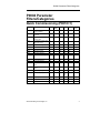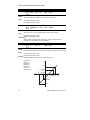
1
SED2 Variable Frequency Drives
Parameter Reference Guide
Item Number 125-3214, Rev. 010
SED2 Variable
Frequency Drives
Parameter Reference
Guide
NOTICE
The information contained within this document is subject to change without
notice and should not be construed as a commitment by Siemens Building
Technologies, Inc. Siemens Building Technologies, Inc. assumes no
responsibility for any errors that may appear in this document.
All software described in this document is furnished under a license and may be
used or copied only in accordance with the terms of such license.
SERVICE STATEMENT
Control devices are combined to make a system. Each control device is
mechanical in nature and all mechanical components must be regularly serviced
to optimize their operation. All Siemens Building Technologies, Inc. branch
offices and authorized distributors offer Technical Support Programs that will
ensure your continuous, trouble-free system performance.
For further information, contact your nearest Siemens Building Technologies, Inc.
representative.
CREDITS
Product or company names mentioned herein may be the trademarks of their
respective owners.
Copyright © 2003 by Siemens Building Technologies, Inc.
TO THE READER
Your feedback is important to us. If you have comments about this manual,
please submit them to [email protected].
Printed in U.S.A.
Table of Contents
Table of Contents
Overview ................................................................................
1
Parameter Structure...........................................................
1
Parameter Indexes.............................................................
1
P0004 Parameter Filters/Categories....................................
3
Quick Commissioning (P0010=1) ......................................
3
Inverter (VFD) Unit (P0004=2)...........................................
4
Motor Data (P0004=3) .......................................................
4
Commands and Digital I/O (P0004=7)...............................
5
Analog I/O (P0004=8) ........................................................
7
Setpoint Channel and Ramp Generator (P0004=10) ........
8
Drive Features (P0004=12) ...............................................
9
Motor Control (P0004=13) ................................................. 10
Communication (P0010=20) .............................................. 11
Alarms, Warnings and Monitoring (P0010=21).................. 12
PI Controller (P0004=22) ................................................... 13
Restore Factory Settings ................................................... 15
Parameter Details (Numeric Listing) ................................... 16
Siemens Building Technologies, Inc.
i
Overview
Overview
The SED2 uses parameters to define the required operating
characteristics, such as motor data, ramp times, and maximum and
minimum frequency. Users enter and modify the SED2 parameters using
the Basic Operator Panel, the Advanced Operator Panel, or a serial
interface.
Each parameter consists of the letter "r" or "P", followed by four
numbers, such as r0000 or P0010. The letter "r" identifies read-only
parameters. The letter "P" identifies programmable parameters.
Parameter Structure
Figure 1 depicts the structure of the SED2 parameters.
•
User Access Level parameter P0003 selects the access level for
using the parameters (1=standard, 2=extended, or 3=expert). The
access level selected via parameter P0003 determines the number
of parameters that are accessible by the user. For most applications,
the Standard (1) and Extended (2) levels are sufficient. The factory
default setting is P0003=1 (Standard).
•
The filters of Parameter Filter P0004 categorize the parameters that
are available via the access level according to functionality. The
filters/categories enable a more focused operational approach. If
Parameter P0004=0 for no filter/category, then all parameters for a
selected user access level are available.
NOTE:
Some parameters are intended for commissioning only and
can be viewed as a function of this filter. In order to set these
parameters, P0010 must be set to 1 (quick commissioning).
Parameter Indexes
Certain parameters have indexes. The indexes provide subsets of a
particular parameter function and group together closely related
parameter type information.
Siemens Building Technologies, Inc.
1
SED2 VFD Parameter Reference Guide
The following indexes are associated with P0700, P1000, and digital
input and output parameters:
IN000 (AUTO), 1st command data set (CDS)
IN001 (HAND), 2nd command data set (CDS)
The following indexes are associated with analog input and output
parameters:
IN000, Analog input 1
IN001, Analog input 2
P0004=22
PI Controller
P0
00
=2
ss Leve
l Ex
pe
rt
cess Leve
lE
xt
s
s
L
e
e
c
ve
l
Ac
P0004=3
Motor Data
, Ac
andard
St
P0003=
1,
03
, Acce
ed
P0004=20
Communication
3= 3
d
en
P0
0
P0004=21
Alarms, Warnings,
and Monitoring
P0004=2
Inverter Unit
P0004=7
Commands and
Digital I/O
P0004=13
Motor Control
P0004=8
Analog I/O
P0004=12
Drive Features
VFD0019R1
P0004=8, P0003=2
Parameters in
Access Levels 1 and 2
associated with
Analog I/O are Available
P0004=10
Setpoint Channel
and Ramp Generator
P0004=8
Analog I/O
P0004=8, P0003=3
Parameters in
Access Levels 1, 2, and 3
associated with
Analog I/O are Available
P0004=8, P0003=1
Parameters in
Access Levels 1
associated with
Analog I/O are Available
Figure 1. SED2 Parameter Access Levels and Filters.
2
Siemens Building Technologies, Inc.
P0004 Parameter Filters/Categories
P0004 Parameter
Filters/Categories
Quick Commissioning (P0010=1)
Parameter
Description
Unit
User
Setting
Min
Default
Access
Level
Max
r0000
Drive display
(defined in P0005)
—
—
—
—
All
P0003
User access level to
parameters
—
0
1
4
1
P0010
Commissioning
parameter filter
—
0
0
30
1
P0100
Europe/North America power
settings (kW or hp)
—
0
0
2
1
P0304
Rated motor voltage
V
10
Varies
2000
1
P0305
Rated motor current
A
0.01
Varies
10000.00
1
P0307
Rated motor power
—
0.01
Varies
2000.00
1
P0308
Rated motor cosPhi
—
0.000
0.000
1.000
3
P0309
Rated motor efficiency
%
0.0
Varies
99.9
3
P0310
Rated motor frequency
Hz
12.00
50.00 or 650.00
60.00
1
P0311
Rated motor speed
0
Varies
40000
1
P0640
Motor overload factor
%
10.0
110.0
400.0
3
P0700
Selection of command
source
—
0
[0] 2,
[1] 1
6
1
P1000
Selection of frequency
setpoint
—
0
2
77
1
P1080
Minimum frequency
Hz
0.00
0.00
650.00
1
P1082
Maximum frequency
Hz
0.00
50.00/
60.00,
Varies
650.00
1
P1120
Ramp—up time
s
0.00
10.00
650.00
1
P1121
Ramp—down time
s
0.00
30.00
650.00
1
P3900
End of quick commissioning
—
0
0
3
1
Siemens Building Technologies, Inc.
1/min
3
SED2 VFD Parameter Reference Guide
Inverter (VFD) Unit (P0004=2)
Parameter
Description
Unit
User
Setting
Min
Default
Access
Level
Max
r0000
Drive display
(defined in P0005)
—
—
—
—
All
P0003
User access level to
parameters
—
0
1
4
1
P0004
Parameter filter
—
0
0
22
1
P0010
Commissioning
parameter filter
—
0
0
30
1
r0018
Firmware version
—
—
—
—
3
r0026
CO: Actual DC link output
voltage
V
—
—
—
3
r0039
CO: Energy consumption
meter
kWh
—
—
—
3
P0040
Reset energy consumption
meter
—
0
0
1
3
r0200
Actual power stack code
number
—
—
—
—
3
r0206
Rated inverter (VFD) power
(kW/hp)
—
—
—
—
3
r0207
Rated inverter (VFD) current
A
—
—
—
3
r0208
Rated inverter (VFD) voltage
V
—
—
—
3
r0209
Maximum inverter (VFD)
current
A
—
—
—
3
P1800
Pulse frequency
kHz
2
Varies
16
2
r1801
CO: Actual switching
frequency
kHz
—
—
—
3
P1820
Reverse output phase
sequence
—
0
0
1
3
Motor Data (P0004=3)
Parameter
Description
Unit
User
Setting
Min
Default
Access
Level
Max
r0000
Drive display
(defined in P0005)
—
—
—
—
All
P0003
User access level to
parameters
—
0
1
4
1
P0004
Parameter filter
—
0
0
22
1
P0010
Commissioning
parameter filter
—
0
0
30
1
r0035
CO: Actual Motor
temperature
°C
—
—
—
3
P0304
Rated motor voltage
V
10
Varies
2000
1
P0305
Rated motor current
A
0.01
Varies
10000.00
1
4
Siemens Building Technologies, Inc.
P0004 Parameter Filters/Categories
Parameter
Description
Unit
User
Setting
Min
Default
Access
Level
Max
P0307
Rated motor power
—
0.01
Varies
2000.00
1
P0308
Rated motor cosPhi
—
0.000
0.000
1.000
3
P0309
Rated motor efficiency
%
0.0
Varies
99.9
3
P0310
Rated motor frequency
Hz
12.00
50.00 or 650.00
60.00
1
1/min
0
Varies
40000
1
r0313
Motor pole pairs
—
—
—
—
3
P0340
Calculation of motor
parameters
—
0
0
4
3
P0350
Stator resistance (line—to—
line)
0.00001 Varies
2000.0
3
3
P0311
Rated motor speed
ohm
r0395
CO: Total stator resistance
%
—
—
—
P0601
Motor temp. sensor
—
0
0
2
3
P0610
Motor I2t temperature
reaction
—
0
2
2
3
P0640
Motor overload factor
P1910
Select motor data
identification
r1912
Identified stator resistance
10.0
110.0
400.0
3
ohm
%
0
0
20
3
—
—
—
—
3
Commands and Digital I/O (P0004=7)
Parameter
Description
Unit
—
r0000
Drive display
(defined in P0005)
r0002
Drive state (actual)
—
P0003
User access level to
parameters
—
User
Setting
Min
—
Default
Access
Level
Max
—
—
All
—
—
—
3
0
1
4
1
P0004
Parameter filter
—
0
0
22
1
P0010
Commissioning
parameter filter
—
0
0
30
1
r0019
CO/BO: BOP control word
—
—
—
—
3
r0050
CO: Active command data
set
—
—
—
—
3
r0052
CO/BO: Actual status word 1
—
—
—
—
3
r0053
CO/BO: Actual status word 2
—
—
—
—
3
r0054
CO/BO: Actual control word
1
—
—
—
—
3
r0055
CO/BO: Additional actual
control word
—
—
—
—
3
P0700
Selection of command
source
—
0
[0] 2,
[1] 1
6
1
Siemens Building Technologies, Inc.
5
SED2 VFD Parameter Reference Guide
Parameter
Description
Unit
User
Setting
Min
Default
Access
Level
Max
P0701
Function of digital input 1
—
0
[0] 1,
[1] 0
99
2
P0702
Function of digital input 2
—
0
[0] 12,
[1] 0
99
2
P0703
Function of digital input 3
—
0
9
99
2
P0704
Function of digital input 4
—
0
15
99
2
P0705
Function of digital input 5
—
0
15
99
2
P0706
Function of digital input 6
—
0
15
99
2
P0707
Function of digital input 7
—
0
0
99
3
P0708
Function of digital input 8
—
0
0
99
3
P0718
CO/BO: Hand/Auto
—
0
0
1
3
r0722
CO/BO: Binary input values
—
—
—
—
3
P0725
PNP/NPN digital inputs
—
0
1
1
3
P0731
BI: Function of digital output
1
—
0:0
52:3
4000:0
2
P0732
BI: Function of digital output
2
—
0:0
52:2
4000:0
2
r0747
CO/BO: State of digital
outputs
—
—
—
—
3
P0748
Invert digital outputs
—
0
0
7
3
P0809
Copy Command Data Set
—
0
0
2
3
P0810
BI: Command Data Set bit 0
(Local/Remote)
—
0:0
718:0
4095:0
3
P1020
BI: Fixed frequency selection
Bit 0
—
0:0
0:0
4000:0
3
P1021
BI: Fixed frequency selection
Bit 1
—
0:0
0:0
4000:0
3
P1022
BI: Fixed frequency selection
Bit 2
—
0:0
0:0
4000:0
3
P1023
BI: Fixed frequency selection
Bit 3
—
0:0
722:3
4000:0
3
P1026
BI: Fixed frequency selection
Bit 4
—
0:0
722:4
4000:0
3
P1028
BI: Fixed frequency selection
Bit 5
—
0:0
722:5
4000:0
3
P1110
BI: Inhibit negative frequency
setpoint
—
0:0
1
4000:0
3
P1140
BI: RFG enable
—
0.00
1.0
4000.0
3
P1141
RFG status
—
0.00
1.0
4000.0
3
P1142
RFG enable
—
0.00
1.0
4000.0
3
P1230
BI: Enable DC braking
—
0:0
0:0
4000:0
3
P1270
BI: Enable essential service
—
0:0
0:0
4000:0
3
6
Siemens Building Technologies, Inc.
P0004 Parameter Filters/Categories
Parameter
User
Setting
Min
Default
Access
Level
Description
Unit
Max
P2220
BI: Fixed PID setpoint select
Bit 0
—
0:0
0:0
4000:0
3
P2221
BI: Fixed PID setpoint select
Bit 1
—
0:0
0:0
4000:0
3
P2222
BI: Fixed PID setpoint select
Bit 2
—
0:0
0:0
4000:0
3
P2223
BI: Fixed PID setpoint select
Bit 3
—
0:0
722:3
4000:0
3
P2226
BI: Fixed PID setpoint select
Bit 4
—
0:0
722:4
4000:0
3
P2228
BI: Fixed PID setpoint select
Bit 5
—
0:0
722:4
4000:0
3
Analog I/O (P0004=8)
Parameter
Description
Unit
User
Setting
Min
Default
Access
Level
Max
r0000
Drive display
(defined in P0005)
—
—
—
—
All
P0003
User access level to
parameters
—
0
1
4
1
P0004
Parameter filter
—
0
0
22
1
P0010
Commissioning
parameter filter
—
0
0
30
1
P0501
Type of sensor
—
0
0
29
2
r0752
Actual input of analog input
(V or mA)
—
—
—
—
2
P0753
Smooth time analog input
ms
0
100
10000
3
r0754
Actual analog input value
after scaling
%
—
—
—
2
r0755
CO: Actual analog input after
scaling (4000h)
—
—
—
—
3
P0756
Type of analog input
—
0
0
5
2
P0757
Value x1 of analog input
scaling (V/mA)
—
-50.00
0
150.0
2
P0758
Value y1 of analog input
scaling
%
—
0.0
99999.9
99999.9
2
P0759
Value x2 of analog input
scaling (V/mA)
—
-50.0
150.0
2
P0760
Value y2 of analog input
scaling
%
—
100.0
99999.9
99999.9
2
P0761
Width of analog input
deadband (V/mA)
—
0
150.0
3
P0771
CI: Analog output
—
0:0
21:0
4000:0
2
P0773
Smooth time analog output
ms
0
100
1000
3
Siemens Building Technologies, Inc.
150.0
0
7
SED2 VFD Parameter Reference Guide
Parameter
Description
Unit
User
Setting
Min
Default
Access
Level
Max
r0774
Actual analog output value
(V or mA)
—
—
—
—
3
P0776
Type of analog output
—
0
1
1
3
P0777
Value x1 of analog output
scaling
%
—
0.0
99999.0
99999.0
2
P0778
Value y1 of analog output
scaling
—
0
20
2
P0779
Value x2 of analog output
scaling
%
—
100.0
99999.0
99999.0
2
P0780
Value y2 of analog output
scaling
—
0
10
20
2
P0781
Width of analog output
deadband
—
0
0
20
3
0
Setpoint Channel and Ramp
Generator (P0004=10)
Parameter
Description
Unit
User
Setting
Min
Default
Access
Level
Max
r0000
Drive display
(defined in P0005)
—
—
—
—
All
P0003
User access level to
parameters
—
0
1
4
1
P0004
Parameter filter
—
0
0
22
1
P0010
Commissioning
parameter filter
—
0
0
30
1
P1000
Selection of frequency
setpoint
—
0
2
77
1
P1001
Fixed frequency 1
Hz
—650.0 0.00
650.00
2
P1002
Fixed frequency 2
Hz
—650.0 5.00
650.00
3
P1003
Fixed frequency 3
Hz
—650.0 10.00
650.00
3
P1004
Fixed frequency 4
Hz
—650.0 15.00
650.00
3
P1005
Fixed frequency 5
Hz
—650.0 20.00
650.00
3
P1006
Fixed frequency 6
Hz
—650.0 25.00
650.00
3
P1007
Fixed frequency 7
Hz
—650.0 30.00
650.00
3
P1008
Fixed frequency 8
Hz
—650.0 35.00
650.00
3
P1009
Fixed frequency 9
Hz
—650.0 40.00
650.00
3
P1010
Fixed frequency 10
Hz
—650.0 45.00
650.00
3
P1011
Fixed frequency 11
Hz
—650.0 50.00
650.00
3
P1012
Fixed frequency 12
Hz
—650.0 55.00
650.00
3
P1013
Fixed frequency 13
Hz
—650.0 60.00
650.00
3
P1014
Fixed frequency 14
Hz
—650.0 65.00
650.00
3
8
Siemens Building Technologies, Inc.
P0004 Parameter Filters/Categories
Parameter
User
Setting
Min
Default
Access
Level
Description
Unit
P1015
Fixed frequency 15
Hz
—650.0 65.00
650.00
3
P1016
Fixed frequency mode—Bit 0
—
1
1
3
3
P1017
Fixed frequency mode—Bit 1
—
1
1
3
3
P1018
Fixed frequency mode—Bit 2
—
1
1
3
3
P1019
Fixed frequency mode—Bit 3
—
1
1
3
3
r1024
CO: Actual fixed frequency
Hz
—
—
—
3
P1025
Fixed frequency mode – Bit
4
—
1
1
3
3
P1027
Fixed frequency mode – Bit
5
—
1
1
2
3
P1031
Setpoint memory of the
motor potentiometer
—
0
1
1
3
P1032
Inhibit reverse direction of
motor potentiometer
—
0
1
1
3
P1040
Setpoint of the motor
potentiometer
Hz
—650.00 10.00
650.00
2
r1050
CO: Actual Output frequency
of the motor potentiometer
—
—
—
3
r1078
CO: Total frequency setpoint
Hz
—
—
—
3
P1080
Minimum frequency
Hz
0.00
10.00
650.00
1
P1082
Maximum frequency
Hz
0.00
50.00/
60.00,
Varies
150.00
1
P1091
Skip frequency 1
Hz
0.00
0.00
650.00
3
P1092
Skip frequency 2
Hz
0.00
0.00
650.00
3
P1093
Skip frequency 3
Hz
0.00
0.00
650.00
3
P1094
Skip frequency 4
Hz
0.00
0.00
650.00
3
P1101
Skip frequency bandwidth
Hz
0.00
2.00
10.00
3
P1120
Ramp—up time
s
0.00
10.00
650.00
1
P1121
Ramp—down time
s
0.00
30.00
650.00
1
P1135
OFF3 ramp—down time
s
0.00
5.00
650.00
3
—
Max
Drive Features (P0004=12)
Parameter
Description
Unit
User
Setting
Min
Default
Access
Level
Max
r0000
Drive display
(defined in P0005)
—
—
—
—
All
P0003
User access level to
parameters
—
0
1
4
1
P0004
Parameter filter
—
0
0
22
1
P0005
Display selection for r0000
—
2
21
2294
2
P0006
Display mode for r0000
—
0
2
4
3
Siemens Building Technologies, Inc.
9
SED2 VFD Parameter Reference Guide
Parameter
Description
Unit
User
Setting
Min
Default
Access
Level
Max
P0010
Commissioning
parameter filter
—
0
0
30
1
P0011
Lock for user-defined
parameter
—
0
0
65535
3
P0012
Key for user-defined
parameter
—
0
0
65535
3
P0013
User-defined parameter
—
0
0
65535
3
P1200
Flying start
—
0
0
6
3
P1202
Motor-current: Flying start
%
10
100
200
3
P1203
Search rate: Flying start
%
10
100
200
3
P1210
Automatic restart
—
0
1
5
3
P1211
Number of restart attempts
—
0
3
10
3
P1212
Time to first restart
s
0
30
1000
3
P1213
Restart time increment
s
0
30
1000
3
P1232
DC braking current
%
0
100
250
3
P1233
Duration of DC braking
s
0
0
250
3
P1236
Compound braking current
%
0
0
250
3
P1240
Configuration of Vdc
controller
—
0
1
3
3
Motor Control (P0004=13)
Parameter
Description
Unit
User
Min
Setting
Default
Access
Level
Max
r0000
Drive display
(defined in P0005)
—
—
—
—
All
P0003
User access level to
parameters
—
0
1
4
1
P0004
Parameter filter
—
0
0
22
1
P0010
Commissioning
parameter filter
—
0
0
30
1
r0020
CO: Actual frequency
setpoint
Hz
—
—
—
3
Hz
—
—
—
3
1/min
—
—
—
3
r0021
CO: Actual frequency
r0022
Actual rotor speed
r0024
CO: Actual output frequency
Hz
—
—
—
3
r0025
CO: Actual output voltage
V
—
—
—
3
r0027
CO: Actual output current
A
—
—
—
3
r0031
Actual torque
—
—
—
—
3
r0032
Actual power
Nm
—
—
—
3
r0056
CO/BO: Status of motor
control
—
—
—
—
3
10
Siemens Building Technologies, Inc.
P0004 Parameter Filters/Categories
Parameter
r0061
Description
Actual rotor speed
Unit
User
Min
Setting
—
—
Default
—
Access
Level
Max
—
3
3
r0086
CO: Actual active current
A
—
—
—
P1300
Control mode
—
0
2
23
3
P1310
Continuous boost
%
0.0
50.0
250.0
3
P1311
Acceleration boost
%
0.0
0.0
250.0
3
P1312
Starting boost
%
0.0
0.0
250.0
3
P1335
Slip compensation
%
0.0
0.0
600.0
3
P1336
Slip limit
%
0
250
600
3
r1337
CO: V/f slip frequency
%
—
—
—
3
Communication (P0010=20)
Parameter
Description
Unit
User
Setting
Min
Default
Access
Level
Max
r0000
Drive display
(defined in P0005)
—
—
—
—
All
P0003
User access level to
parameters
—
0
1
4
1
P0004
Parameter filter
—
0
0
22
1
P0010
Commissioning
parameter filter
—
0
0
30
1
P0918
Communication board
address
—
0
3
65535
3
P0927
Parameter changeable via
—
0
—
15
3
r0967
Control word 1
—
—
—
—
3
r0968
Status word 1
—
—
—
—
3
P0971
Transfer data from RAM to
EEPROM
—
0
0
1
3
P2000
Reference frequency
Hz
1.00
50/60
650.00
2
P2001
Reference voltage
V
10
1000
2000
3
P2002
Reference current
A
0.10
Varies
10000.00
3
P2009
USS normalization
—
0
0
1
3
P2010
USS baud rate
—
4
6
12
3
P2011
USS address
—
0
0
31
3
P2014
USS telegram off time
ms
0
0
65535
3
P2040
CB telegram off time
ms
0
20
65535
3
P2041
CB parameter
—
0
0
65535
3
r2050
PZD from CB
—
—
—
—
3
P2051
CI: PZD to CB
—
0:0
52:0
4000:0
3
r2053
Communication board
identification
—
—
—
—
3
Siemens Building Technologies, Inc.
11
SED2 VFD Parameter Reference Guide
Parameter
r2054
Description
Communication board
diagnosis
Unit
User
Setting
—
Min
—
Default
—
Access
Level
Max
—
3
Alarms, Warnings and Monitoring
(P0010=21)
Parameter
Description
Unit
User
Setting
Min
Default
Access
Level
Max
r0000
Drive display
(defined in P0005)
—
—
—
—
All
P0003
User access level to
parameters
—
0
1
4
1
P0004
Parameter filter
—
0
0
22
1
P0010
Commissioning
parameter filter
—
0
0
30
1
r0947
Last fault code
—
—
—
—
3
r0948
Fault time
—
—
—
—
3
r0949
Fault value
—
—
—
—
3
P0952
Total number of faults
—
0
0
8
3
P2100
Alarm number selection
—
0
0
65535
3
P2101
Stop reaction value
—
0
0
5
3
r2110
Warning number
—
—
—
—
3
P2111
Total number of warnings
—
0
0
4
3
r2114
Run time counter
—
—
—
—
3
P2115
AOP real time clock
—
0
0
65535
3
P2155
Threshold frequency f_1
Hz
0.00
30.00
650.00
3
P2156
Delay time of threshold
frequency f_1
ms
0
10
10000
3
P2167
Switch-off frequency f_off
Hz
0.00
1.00
10.00
3
P2168
Delay time T_off
ms
0
10
10000
3
P2181
Belt failure detection mode
—
0
0
6
3
P2182
Belt threshold frequency 1
Hz
0.00
5.00
650.00
3
P2183
Belt threshold frequency 2
Hz
0.00
30.00
650.00
3
P2184
Belt threshold frequency 3
Hz
0.00
50.00
650.00
P2185
Upper torque threshold 1
Nm
0.0
99999.0 99999.0
3
P2186
Lower torque threshold 1
Nm
0.0
0.0
3
P2187
Upper torque threshold 2
Nm
0.0
99999.0 99999.0
3
P2188
Lower torque threshold 2
Nm
0.0
0.0
3
P2189
Upper torque threshold 3
Nm
0.0
99999.0 99999.0
3
P2190
Lower torque threshold 3
Nm
0.0
0.0
3
12
99999.0
99999.0
99999.0
3
Siemens Building Technologies, Inc.
P0004 Parameter Filters/Categories
Parameter
P2191
Description
Belt failure speed tolerance
Unit
User
Setting
Min
Default
Hz
0.00
3.00
Access
Level
Max
20.00
3
P2192
Time delay for belt failure
s
0
10
65
3
r2197
CO/BO: Monitoring word 1
—
—
—
—
3
r2198
CO/BO: Monitoring word 2
—
—
—
—
3
PI Controller (P0004=22)
Parameter
Description
Unit
User
Setting
Min
Default
Access
Level
Max
r0000
Drive display
(defined in P0005)
—
—
—
—
All
P0003
User access level to
parameters
—
0
1
4
1
P0004
Parameter filter
—
0
0
22
1
P0010
Commissioning
parameter filter
—
0
0
30
1
P2200
BI: Enable PID controller
—
0:0
0:0
4000:0
2
P2201
Fixed PID setpoint 1
%
—200.00
0.00
200.00
3
P2202
Fixed PID setpoint 2
%
—200.00
10.00
200.00
3
P2203
Fixed PID setpoint 3
%
—200.00
20.00
200.00
3
P2204
Fixed PID setpoint 4
%
—200.00
30.00
200.00
3
P2205
Fixed PID setpoint 5
%
—200.00
40.00
200.00
3
P2206
Fixed PID setpoint 6
%
—200.00
50.00
200.00
3
P2207
Fixed PID setpoint 7
%
—200.00
60.00
200.00
3
P2208
Fixed PID setpoint 8
%
—200.00
70.00
200.00
3
P2209
Fixed PID setpoint 9
%
—200.00
80.00
200.00
3
P2210
Fixed PID setpoint 10
%
—200.00
90.00
200.00
3
P2211
Fixed PID setpoint 11
%
—200.00
100.00
200.00
3
P2212
Fixed PID setpoint 12
%
—200.00
110.00
200.00
3
P2213
Fixed PID setpoint 13
%
—200.00
120.00
200.00
3
P2214
Fixed PID setpoint 14
%
—200.00
130.00
200.00
3
P2215
Fixed PID setpoint 15
%
—200.00
130.00
200.00
3
P2216
Fixed PID setpoint mode—
Bit 0
—
1
1
3
3
P2217
Fixed PID setpoint mode—
Bit 1
—
1
1
3
3
P2218
Fixed PID setpoint mode—
Bit 2
—
1
1
3
3
P2219
Fixed PID setpoint mode—
Bit 3
—
1
1
3
3
r2224
CO: Actual fixed PID setpoint
%
—
—
—
3
Siemens Building Technologies, Inc.
13
SED2 VFD Parameter Reference Guide
Parameter
Description
Unit
User
Setting
Min
Default
Access
Level
Max
P2225
Fixed PID setpoint mode—
Bit 4
—
1
1
2
3
P2227
Fixed PID setpoint mode—
Bit 5
—
1
1
2
3
P2231
Setpoint memory of PID—
MOP
—
0
1
1
3
P2232
Inhibit rev. direct. of PID—
MOP
—
0
1
1
3
P2240
Setpoint of PID—MOP
%
—200.00
10.00
200.00
3
r2250
CO: Output setpoint of PID—
MOP
%
—
—
—
3
P2253
CI: PID setpoint
—
0:0
2250:0
4000:0
3
P2254
CI: PID trim
—
0:0
0:0
4000:0
3
P2261
PID setpoint filter
—
0.00
0.00
60.00
3
r2262
CO: Actual PID filtered
setpoint
%
—
—
—
3
P2264
CI: PID feedback
—
0:0
755:1
4000:0
3
P2265
PID feedback filter time
constant
s
0.00
0.00
60.00
3
P2267
Maximum value for PID
feedback
%
—200.00
150.00
200.00
3
P2268
Minimum value for PID
feedback
%
—200.00
0.00
200.00
3
P2269
Gain applied to PID
feedback
—
0.00
100.00
500.00
3
P2270
PID feedback function
selector
—
0
0
3
3
P2271
PID transducer type
—
0
0
1
3
r2272
CO: PID scaled feedback
%
—
—
—
3
r2273
CO: PID error
%
—
—
—
3
P2274
PID derivative time
s
0
0
65535
2
3
P2279
PID neutral zone
%
0.00
0.00
100.00
P2280
PID proportional gain
—
0.000
1.200
65.000
2
P2285
PID integral time
s
0
30
65535
2
P2291
PID output upper limit
%
0.00
100.00
100.00
2
P2292
PID output lower limit
%
—200.00
0.00
200.00
2
P2293
PID limit ramp time
s
0.00
0.00
100.00
3
r2294
CO: Actual PID output
%
—
—
—
3
P2303
PID output offset
—
0.0
0.0
4000.0
2
P2304
PID opening time
—
0
0
65535
2
P2305
PID closing time
—
0
0
65535
2
P2306
PID action
—
0
1
1
2
14
Siemens Building Technologies, Inc.
P0004 Parameter Filters/Categories
Parameter
Description
Unit
User
Setting
Min
Default
Access
Level
Max
P2370
Selection of motor staging
stop mode
—
0
0
1
3
P2371
Selection of external motor
configuration
—
0
0
8
3
P2372
Enable motor cycling
—
0
0
1
3
P2373
Motor staging hysteresis
%
0.0
20.0
200.0
3
P2374
Motor staging delay
s
0
30
650
3
P2375
Motor destaging delay
s
0
30
650
3
P2376
Delay override
%
0.0
25.0
200.0
3
P2377
Delay override lockout timer
s
0
30
650
3
P2378
Staging frequency f, %fmax
%
0.0
50.0
120.0
3
r2379
CO/BO: Status of motor
staging
—
—
—
—
3
P2380
Motor hours run
h
0
0
100000
3
P2390
Hibernation setpoint
%
-200.00
0.00
200.00
3
P2391
Hibernation timer
s
0
0
254
3
P2392
Restart PID error
%
-200.00
0.00
200.00
3
Restore Factory Settings
Parameter
Description
Unit
User
Setting
Min
Default
Access
Level
Max
P0003
User access level
—
0
1
4
1
P0010
Commissioning
parameter filter
—
0
0
30
1
P0970
Factory reset
—
0
0
1
1
Siemens Building Technologies, Inc.
15
SED2 VFD Parameter Reference Guide
Parameter Details (Numeric
Listing)
r0000
Drive display
Min:
Unit:
-
Level 1
Def:
-
Max:
-
Details:
Displays user-selected output, defined via P0005.
Note:
Pressing the Fn button for 2 seconds allows you to view the values of DC link
voltage, output frequency, output current, and the selected r0000 setting (defined
via P0005).
r0002
Drive state
Min:
Unit:
-
Level 3
Def:
-
Max:
-
Details:
Displays actual SED2 state.
Enum:
0 Commissioning mode (P0010=0)
1 SED2 ready
2 SED2 fault active
3 SED2 starting (DC-link precharging)
4 SED2 running
5 Stopping (ramping down)
Dependency:
State 3 is visible only while precharging the DC link and when an externally
powered communications module is installed.
P0003
User access level
Min:
Unit:
0
-
Def:
Level 1
1
Max:
4
Details:
Defines user access level to parameters. The default setting (standard) is
sufficient for most simple applications.
Enum:
0
1
2
3
4
16
User-defined parameter list; see P0013 for details.
Standard: For access to the most frequently used parameters.
Extended: For access to additional parameters for supplemental operations
such as SED2 I/O functions.
Expert: For skilled, authorized users familiar with SED2 operations and
functions.
Service: For use by trained, authorized service personal only; password
protected.
Siemens Building Technologies, Inc.
Parameter Details (Numeric Listing)
P0004
Parameter filter
Min:
Unit:
0
-
Def:
Level 1
0
Max:
22
Details:
Filters available parameters according to functionality to enable a more focused
operational approach.
Enum:
0
2
3
4
5
7
8
10
12
13
20
21
22
All parameters
SED2 drive
Motor
Speed sensor
Technology application/units
Commands, binary I/O
Analog inputs and analog outputs
Setpoint channel/remote frequency generator
SED2 features
Motor control
Communication
Alarms/warnings/monitoring
Technology controller (such as PID controller)
Example:
P0004=22 specifies that only PID parameters will be visible.
Note:
The SED2 will start with any setting of P0004.
P0005
Display selection
Min:
Unit:
2
-
Def:
Level 2
21
Max:
2294
Details:
Selects display for parameter r0000 (SED2 display).
Settings:
21
25
26
27
Actual frequency
Output voltage
DC link voltage
Output current
Note:
These settings refer to read only parameter numbers ("rxxxx").
Reference:
See relevant "rxxxx" parameter descriptions.
Siemens Building Technologies, Inc.
17
SED2 VFD Parameter Reference Guide
P0006
Display mode
Min:
Unit:
0
-
Def:
Level 3
2
Max:
4
Details:
Defines mode of display for r0000 (SED2 display).
Enum:
0
1
2
3
4
In ready state, display alternates between setpoint and output frequency. In
run state, display shows output frequency.
In ready state, display shows setpoint. In run state, display shows output
frequency.
In ready state, display alternates between P0005 value and r0020 value. In
run state, display shows P0005 value.
In ready state, display alternates between r0002 value and r0020 value. In
run state, display shows r0002 value.
In all states, display shows P0005 value.
Note:
When SED2 is not running, the display alternates between the values for "Not
Running" and "Running".
P0010
Commissioning parameter filter
Min:
Unit:
0
-
Def:
0
Max:
Level 1
30
Details:
Filters parameters so that only those related to a particular functional group are
selected.
Enum:
0 Ready
1 Quick commissioning
2 SED2
29 Download
30 Factory setting
Dependency:
Reset to 0 for SED2 to run.
P0003 (user access level) determines access to commissioning parameters.
Note:
If P3900 is not 0 (P3900=0 is the default), this parameter is automatically reset
to 0.
18
Siemens Building Technologies, Inc.
Parameter Details (Numeric Listing)
P0011
Lock for user-defined parameter
Min:
Unit:
0
-
Def:
0
Max:
Level 3
65535
Details:
See P0013 (user-defined parameter).
P0012
Key for user-defined parameter
Min:
Unit:
0
-
Def:
0
Level 3
Max:
65535
Max:
65535
Details:
See P0013 (user-defined parameter).
P0013[20] User-defined parameter
Min:
Unit:
0
-
Def:
0
Level 3
Details:
Defines a limited set of parameters to which the end user will have access.
To use, do the following:
1. Set P0003=3 (expert user access level).
2. Access P0013 indexes 0 to 16 (user-defined parameter list).
3. In P0013 index 0 to 16, enter the parameters required to be visible in the
user-defined parameter list.
The following values are fixed and cannot be changed:
- P0013 index 19=12 (key for user-defined parameter)
- P0013 index 18=10 (commissioning parameter filter)
- P0013 index 17=3 (expert user access level)
4.
Set P0003=0 to activate the user-defined parameter list.
Index:
P0013[0]=1st user parameter
P0013[1]=2nd user parameter
P0013[2]=3rd user parameter
P0013[3]=4th user parameter
P0013[4]=5th user parameter
P0013[5]=6th user parameter
P0013[6]=7th user parameter
P0013[7]=8th user parameter
P0013[8]=9th user parameter
P0013[9]=10th user parameter
P0013[10]=11th user parameter
Siemens Building Technologies, Inc.
P0013[11]=12th user parameter
P0013[12]=13th user parameter
P0013[13]=14th user parameter
P0013[14]=15th user parameter
P0013[15]=16th user parameter
P0013[16]=17th user parameter
P0013[17]=18th user parameter
P0013[18]=19th user parameter
P0013[19]=20th user parameter
19
SED2 VFD Parameter Reference Guide
Dependency:
First, set P0011 ("lock") to a different value than P0012 ("key") to prevent
changes to user-defined parameter list. Then, set P0003=0 to activate the userdefined parameter list.
When locked and when the user-defined parameter is activated, the only way to
exit the user-defined parameter list (and to view other parameters) is to set
P0012 ("key") to the value in P0011 ("lock").
Note:
Alternatively, set P0010=30 (commissioning parameter filter, factory setting) and
P0970=1 (factory reset) to perform a complete factory reset.
The default values of P0011 ("lock") and P0012 ("key") are the same.
r0018
Firmware version
Min:
Unit:
-
Def:
Level 3
-
Max:
-
Details:
Displays version number of installed firmware.
r0019
CO/BO: BOP control word
Min:
Unit:
-
Def:
-
Level 3
Max:
-
Details:
Displays status of operator panel commands.
The following settings are used as the "source" codes for keypad control when
connecting to BiCo input parameters.
Bitfields:
Bit00
Bit02
Bit03
Bit01
Bit08
Bit11
Bit12
Bit13
Bit14
Bit15
ON/OFF1
Reserved
Reserved
OFF2: Electrical stop
JOG right
Reverse (setpoint inversion)
Hand Operation
Motor potentiometer up
Motor potentiometer down
Auto Operation
0 NO
1 YES
0
0
0
0
0
0
0
1
1
1
1
1
1
1
YES
NO
NO
NO
NO
NO
NO
NO
YES
YES
YES
YES
YES
YES
Note:
When BiCo technology is used to allocate functions to panel buttons, this
parameter displays the actual status of the relevant command.
The following functions can be "connected" to individual buttons:
•
•
•
•
•
•
20
ON/OFF1
OFF2
JOG
REVERSE
INCREASE
DECREASE
Siemens Building Technologies, Inc.
Parameter Details (Numeric Listing)
r0020
CO: Actual frequency setpoint
Min:
Unit:
Hz
Def:
-
Max:
Level 3
-
Details:
Displays actual frequency setpoint (output from ramp function generator).
r0021
CO: Actual frequency
Min:
Unit:
Hz
Def:
-
Level 3
Max:
-
Details:
Displays actual output frequency (r0024), excluding slip compensation,
resonance damping, and frequency limitation.
r0022
Actual rotor speed
Min:
Unit:
1/min
Def:
Level 3
-
Max:
-
Details:
Displays calculated rotor speed based on SED2 output frequency Hz x
120/number of poles.
Note:
This calculation makes no allowance for load-dependent slip.
r0024
CO: Actual output frequency
Min:
Unit:
Hz
Def:
-
Max:
Level 3
-
Details:
Displays actual output frequency, including slip compensation, resonance
damping, and frequency limitation.
r0025
CO: Actual output voltage
Min:
Unit:
V
Def:
-
Level 3
Max:
-
Details:
Displays rms voltage applied to motor.
r0026[2]
CO: Actual DC-link voltage
Min:
Unit:
V
Def:
-
Max:
Level 3
-
Details:
Displays DC-link voltage.
Siemens Building Technologies, Inc.
21
SED2 VFD Parameter Reference Guide
r0027
CO: Actual output current
Min:
Unit:
A
Def:
-
Level 3
Max:
-
Details:
Displays rms value of motor current (A).
Note:
For asynchonous motors, a limit is calculated for the torque generating current
component to prevent motor stalling. This limit is calculated in conjunction with
the maximum possible output voltage, motor leakage, and current field
weakening.
r0031
CO: Actual torque
Min:
Unit:
Nm
Def:
Level 3
-
Max:
-
-
Max:
-
Details:
Displays motor torque.
r0032
CO: Actual power
Min:
Unit:
-
Def:
Level 3
Details:
Displays motor power.
Dependency:
Value displays in kW or hp depending on setting for P0100 (operation for
Europe/North America).
r0035
CO: Actual motor temperature
Min:
Unit:
°C
Def:
-
Max:
Level 3
-
Details:
Displays measured motor temperature.
r0039
CO: Energy consumption meter (kWh)
Min:
Unit:
kWh
Def:
-
Max:
Level 3
-
Details:
Displays electrical energy used by SED2 since display was last reset (see
P0040, reset energy consumption meter).
Dependency:
Value is reset via P3900=1 (end quick commissioning), P0970=1 (factory reset),
or P0040=1 (reset energy consumption meter).
22
Siemens Building Technologies, Inc.
Parameter Details (Numeric Listing)
P0040
Reset energy consumption meter
Min:
Unit:
0
-
Def:
0
Max:
Level 3
1
Details:
Resets value of parameter r0039 (energy consumption meter) to zero.
Enum:
0 No reset
1 Reset r0039 to 0
Dependency:
No reset until you press P.
r0050
CO/BO Active command data set
Min:
Unit:
-
Def:
-
Max:
Level 3
-
Details:
Displays currently selected and active binector and connector (BiCo) data set.
Enum:
0
1
r0052
1st Command data set (CDS)
2nd Command data set (CDS)
CO/BO: Actual status word 1
Min:
Unit:
-
Def:
-
Max:
Level 3
-
Details:
Displays first status word of SED2 (bit format). Can be used to diagnose SED2
status.
Bitfields:
Bit00
Bit01
Bit02
Bit03
Bit04
Bit05
Bit06
Bit07
Bit08
Bit09
Bit10
Bit11
Bit12
Bit13
Bit14
Bit15
SED2 ready
SED2 ready to run
SED2 running
SED2 fault active
OFF2 active
OFF3 active
ON inhibit active
SED2 warning active
Deviation setpoint/Actual value
PZD control
Maximum frequency reached
Warning: Motor current limit
Motor holding brake active
Motor overload
Motor runs direction right
SED2 overload
0
0
0
0
0
0
0
0
0
0
0
0
0
0
0
0
NO
NO
NO
NO
YES
YES
NO
NO
YES
NO
NO
YES
NO
YES
NO
YES
1
1
1
1
1
1
1
1
1
1
1
1
1
1
1
1
YES
YES
YES
YES
NO
NO
YES
YES
NO
YES
YES
NO
YES
NO
YES
NO
Note:
Output of Bit3 (Fault) will be inverted on digital output (Low=Fault, High=No
Fault).
Siemens Building Technologies, Inc.
23
SED2 VFD Parameter Reference Guide
r0053
CO/BO: Actual status word 2
Min:
Unit:
-
Def:
-
Level 3
Max:
-
Details:
Displays second status word of SED2 (bit format).
Bitfields:
Bit00
Bit01
Bit02
Bit03
Bit04
Bit05
Bit06
Bit07
Bit08
Bit09
Bit10
Bit11
Bit12
Bit13
Bit14
Bit15
r0054
DC brake active
Actual frequency r0021>P2167 (f_off)
Actual frequency r0021>P1080 (f_min)
Actual current r0027>=P0305
Actual frequency r0021>=P2155 (f_1)
Actual frequency r0021<P2155 (f_1)
Actual frequency r0021>=setpoint
Actual Vdc r0026<800V
Actual Vdc r0026>800V
Ramping finished
PID output r2294 == P2292 (PID_min)
PID output r2294 == P2291 (PID_max)
Reserved
Reserved
Download data set 0 from AOP
Download data set 1 from AOP
0
0
0
0
0
0
0
0
0
0
0
0
NO
NO
NO
NO
NO
NO
NO
NO
NO
NO
NO
NO
1
1
1
1
1
1
1
1
1
1
1
1
0 NO
0 NO
YES
YES
YES
YES
YES
YES
YES
YES
YES
YES
YES
YES
1 YES
1 YES
CO/BO: Actual control word 1
Min:
Unit:
-
Def:
-
Level 3
Max:
-
Details:
Displays first control word of SED2 and can be used to diagnose which
commands are active.
Bitfields:
Bit00
Bit01
Bit02
Bit03
Bit04
Bit05
Bit06
Bit07
Bit08
Bit09
Bit10
Bit11
Bit13
Bit14
Bit15
24
ON/OFF1
OFF2: Electrical stop
OFF3: Fast stop
Pulse enable
RFG (ramp function gen.) enable
RFG (ramp function gen.) start
Setpoint enable
Fault acknowledge
JOG righ
JOG left
Control from PLC
Reverse (setpoint inversion)
Motor potentiometer MOP up
Motor potentiometer MOP down
CDS Bit 0 (Local/Remote)
0
0
0
0
0
0
0
0
0
0
0
0
0
0
0
NO
YES
YES
NO
NO
NO
NO
NO
NO
NO
NO
NO
NO
NO
NO
1
1
1
1
1
1
1
1
1
1
1
1
1
1
1
YES
NO
NO
YES
YES
YES
YES
YES
YES
YES
YES
YES
YES
YES
YES
Siemens Building Technologies, Inc.
Parameter Details (Numeric Listing)
r0055
CO/BO: Additional Actual control word
Min:
Unit:
-
Def:
-
Max:
Level 3
-
Details:
Displays additional control word of SED2.
Bitfields:
Bit00
Bit01
Bit02
Bit03
Bit08
Bit09
Bit11
Bit12
Bit13
r0056
Fixed frequency Bit 0
Fixed frequency Bit 1
Fixed frequency Bit 2
Fixed frequency Bit 3
PID enabled
DC brake enabled
Droop
Torque control
External fault 1
0
0
0
0
0
0
0
0
0
NO
NO
NO
NO
NO
NO
NO
NO
YES
1
1
1
1
1
1
1
1
1
YES
YES
YES
YES
YES
YES
YES
YES
NO
CO/BO: Status of motor control
Min:
Unit:
-
Def:
-
Max:
Level 3
-
Details:
Displays status of motor control and can be used to diagnose SED2 status.
Bitfields:
Bit00
Bit01
Bit02
Bit03
Bit04
Bit05
Bit06
Bit07
Bit08
Bit09
Bit10
Bit11
Bit12
Bit13
Bit14
Bit15
r0061
Initial control finished
Motor demagnetizing finished
Pulses enabled
Voltage soft start select
Motor excitation finished
Starting boost active
Acceleration boost active
Frequency is negative
Field weakening active
Volts setpoint limited
Slip frequency limited
F_out > F_max Frequency limited
Phase reversal selected
I-max controller active
Vdc-max controller active
Vdc-min controller active
0
0
0
0
0
0
0
0
0
0
0
0
0
0
0
0
CO: Actual rotor speed
Min:
Unit:
Hz
Def:
-
NO
NO
NO
NO
NO
NO
NO
NO
NO
NO
NO
NO
NO
NO
NO
NO
1
1
1
1
1
1
1
1
1
1
1
1
1
1
1
1
YES
YES
YES
YES
YES
YES
YES
YES
YES
YES
YES
YES
YES
YES
YES
YES
Level 3
Max:
-
Details:
Displays current speed detected by encoder.
Siemens Building Technologies, Inc.
25
SED2 VFD Parameter Reference Guide
r0086
CO: Actual active current
Min:
Unit:
A
Def:
-
Level 3
Max:
-
Details:
Displays active (real part) of motor current.
Dependency:
Applies when V/f control is selected in P1300 (control mode); otherwise, the
display shows the value zero.
P0100
Europe/North America
Min:
Unit:
0
-
Def:
0
Level 1
Max:
2
Details:
Determines whether power settings (such as, P0307 rated motor power) are
expressed in kW or hp.
The setting of P100 automatically determines the default settings for P0310
nominal rating plate frequency, P1082 maximum motor frequency, and P2000
reference frequency.
Enum:
0 Europe (kW), frequency 50 Hz, default
1 North America (hp), frequency 60 Hz
2 North America (kW), frequency 60 Hz
Dependency:
The setting of DIP switch 2 on the control module (under the I/O module)
determines the validity of P0100 settings 0 and 1 according to the following table:
DIP Switch 2
Position
Power and
Frequency
P0100
Setting
Power and
Frequency
Off
kW, 50 Hz
Overwrites
1
hp, 60 Hz
On
hp, 60 Hz
Overwrites
0
kW, 50 Hz
Before you change this parameter, stop the SED2 (that is, disable all pulses).
P0010=1 (commissioning mode) enables changes to be made.
Changing P0100 resets all rated motor parameters as well as other parameters
that depend on the rated motor parameters (see P0340, calculation of motor
parameters).
Note:
P0100 setting 2 (North America kW, frequency default 60 Hz) is not overwritten
by the setting of DIP switch 2.
26
Siemens Building Technologies, Inc.
Parameter Details (Numeric Listing)
r0200
Actual power stack code number
Min:
Unit:
-
Def:
-
Max:
Level 3
-
Details:
Identifies hardware variant.
Note:
Parameter r0200=0 indicates that no power stack has been identified.
r0206
Rated SED2 power (kW)/(hp)
Min:
Unit:
-
Def:
-
Level 3
Max:
Details:
Displays nominal rated motor power from SED2.
Dependency:
Value displayse in kW or hp depending on setting for P0100 (operation for
Europe/North America).
r0207
Rated SED2 current
Min:
Unit:
A
Def:
-
Level 3
Max:
-
Details:
Displays maximum continuous output current of SED2.
r0208
Rated SED2 voltage
Min:
Unit:
V
Def:
-
Level 3
Max:
-
Details:
Displays nominal AC supply voltage of SED2.
Value:
r0208=230 : 200 to 240V +/- 10%
r0208=400 : 380 to 480V +/- 10%
r0208=575 : 500 to 600V +/- 10%
r0209
Maximum SED2 current
Min:
Unit:
A
Def:
-
Level 3
Max:
Details:
Displays maximum output current of SED2.
Siemens Building Technologies, Inc.
27
SED2 VFD Parameter Reference Guide
P0304
Rated motor voltage
Min:
Unit:
10
V
Def:
Level 1
Varies
Max:
2000
Details:
Defines nominal motor voltage (V) from rating plate. The following diagram
shows a typical rating plate with the locations of relevant motor data.
Dependency:
Changeable only when P0010=1 (quick commissioning).
P0307
SIEMENS
P0304
P0310
VFD0032R1
P0305
P0311
P0309
P0305
PE 21 PLUS TM
PREMIUM EFFICIENCY
LOW VOLTAGE
CONNECTION
4
6
5
Type : RGZZESD
Rating : Cont
HP : 3
Ins Class : F
7
8
9
Volts : 230YY/460Y
Serv Factor : 1,0
1
2
3
Amps : 7,8 / 3,9
Amb Temp : 40 o C
LINE
RPM : 1740
Temp Rise : Class B
HIGH VOLTAGE
NEMA nom Eff : 87,5 %
NEMA design : B
CONNECTION
4
5
6
Frame : 182 T
KVA Code : K
Sh end brg : 30BC02JP3
Weight : 95 lbs
7
8
9
Opp end brg : 30BC02JP3
Serial No : M00T0194 CE 18 1 2 3
Part No : 1MJP1824YP60 LR 39020
LINE
TEFC
3 PH
60 Hz
Rated motor current
Min:
Unit:
0.01
A
Def:
Varies
Level 1
Max:
10000.00
Details:
Defines nominal motor current (A) from rating plate; see diagram in P0304.
Dependency:
Changeable only when P0010=1 (quick commissioning).
Note:
For asynchronous motors, the maximum value is the maximum SED2 current
(r0209).
For synchronous motors, the maximum value is twice the maximum SED2
current (r0209).
The minimum value is 1/32 times SED2 rated current (r0207).
28
Siemens Building Technologies, Inc.
Parameter Details (Numeric Listing)
P0307
Rated motor power
Min:
Unit:
0.01
-
Def:
Varies
Level 1
Max:
2000.00
Details:
Defines nominal motor power (kW/hp) from rating plate; see diagram in P0304.
Dependency:
If P0100=1 (hp, frequency 60 Hz), values will be in hp, see diagram P0304
(rating plate).
Changeable only when P0010=1 (quick commissioning).
P0308
Rated motor cosPhi
Min:
Unit:
0.000
-
Def:
0.000
Level 3
Max:
1.000
Details:
Defines nominal motor power factor (cosPhi) from rating plate.
Dependency:
Changeable only when P0010=1 (quick commissioning).
Visible only when P0100=0 or 2 (motor power entered in kW).
Setting 0 causes internal calculation of value.
P0309
Rated motor efficiency
Min:
Unit:
0.0
%
Def:
Varies
Level 3
Max:
99.9
Details:
Defines nominal motor efficiency in % from rating plate; see diagram in P0304.
Dependency:
Changeable only when P0003=3 (expert user access level) and P0010=1 (quick
commissioning).
Visible only when P0100=1 (motor power entered in hp).
Setting 0 causes internal calculation of value.
Note:
P0309=100% corresponds to superconducting.
P0310
Rated motor frequency
Min:
Unit:
12.00
Hz
Def: 50.00
or 60.00
Level 1
Max:
650.00
Details:
Defines nominal motor frequency (Hz) from rating plate; see diagram in P0304.
Dependency:
Changeable only when P0010=1 (quick commissioning).
Pole pair number is recalculated automatically if parameter is changed.
Siemens Building Technologies, Inc.
29
SED2 VFD Parameter Reference Guide
P0311
Rated motor speed
Min:
Unit:
0
1/min
Def:
Varies
Level 1
Max:
40000
Details:
Defines nominal motor speed (rpm) from rating plate; see diagram in P0304.
Dependency:
Changeable only when P0010=1 (quick commissioning).
Setting 0 causes an internal calculation of the value.
Required for vector control and V/f control with speed controller.
Slip compensation in V/f control requires rated motor speed for correct operation.
Pole pair number is recalculated automatically if parameter is changed.
r0313
Motor pole pairs
Min:
Unit:
-
Def:
Level 3
-
Max:
-
Details:
Displays number of motor pole pairs that the SED2 is currently using for internal
calculations.
Value:
r0313=1 : 2-pole motor
r0313=2 : 4-pole motor
Dependency:
Pole pair number is recalculated automatically if P0310 rated motor frequency or
P0311 rated motor speed is changed.
P0340
Calculation of motor parameters
Min:
Unit:
0
-
Def:
0
Max:
Level 3
4
Details:
Calculates various motor parameters, including:
P0350 stator resistance
P2000 reference frequency
P2002 reference current
Enum:
0
1
2
3
4
No calculation
Complete programming
Calculate equivalent circuit data
Calculate V/f and vector control
Calculate only controller setting
Note:
This parameter is required during commissioning to optimize SED2 performance.
30
Siemens Building Technologies, Inc.
Parameter Details (Numeric Listing)
P0350
Stator resistance (line-to-line)
Min:
Unit:
0.00001 Def:
Ohm
Varies
Max:
Level 3
2000.0
Details:
Stator resistance value (ohms) for connected motor (from line-to-line). The value
includes the cable resistance.
There are three ways to determine the value for this parameter:
•
Calculate using P0340=1 (data entered from rating plate) or P3900=1, 2, or
3 (end of quick commissioning).
•
Measure using P1910=1 (motor data identification; value for stator
resistance is overwritten).
•
Measure manually using an ohmmeter.
Note:
Since measured line-to-line, this value may appear to be up to two times higher
than expected.
The value entered in P0350 stator resistance is the value obtained by the mostrecently used method.
r0395
CO: Total stator resistance, %
Min:
Unit:
%
Def:
-
Max:
Level 3
-
Details:
Displays stator resistance of motor as a % of combined stator/cable resistance.
P0400
Select encoder type
Min:
Unit:
0
-
Def:
0
Level 3
Max:
12
Details:
Selects encoder type.
The term "quadrature" in settings 2 and 12 refers to two periodic functions
separated by a quarter cycle or 90 degrees.
Enum:
0
1
2
3
12
P0409
Disabled
Single channel encoder
Quadrature encoder without zero pulse
External pulse train
Quadrature encoder with zero pulse
Pulses per second at rated frequency
Min:
Unit:
1
-
Def:
25
Max:
Level 3
500
Details:
Sets number of pulses per second at rated speed.
Siemens Building Technologies, Inc.
31
SED2 VFD Parameter Reference Guide
P0501[2]
Type of Sensor
Min:
Unit:
0
-
Def:
Level 2
0
Max:
29
Details:
Configures each analog input for a type of process variable sensor. Setting
P0501 also sets P0756, type of analog input.
Switching between voltage and current input types also requires that I/O module
DIP switches are set accordingly.
Enum:
0
No sensor selected
16 Sensor type 0 to 2 inch-wc
1
Sensor type QBE620 P1
17 Sensor type 0 to 2.5 inch-wc
2
Sensor type QBE620 P10
18 Sensor type 0 to 3 inch-wc
3
Sensor type QBE620 P16
19 Sensor type 0 to 5 inch-wc
4
Sensor type QBE620 P25
20 Sensor type 0 to 10 inch-wc
5
Sensor type QBE620 P40
21 Sensor type 0 to 10 psi
6
Sensor type QBE620 P4
22 Sensor type 0 to 15 psi
7
Sensor type QBE620 P5
23 Sensor type 0 to 25 psi
8
Sensor type QBE621 P10U
24 Sensor type 0 to 30 psi
9
Sensor type QBE621 P25U
25 Sensor type 0 to 50 psi
10 Sensor type QBE63 DP01
26 Sensor type 0 to 60 psi
11 Sensor type QBE63 DP02
27 Sensor type 0 to 100 psi
12 Sensor type QBE63 DP05
28 Sensor type 0 to 150 psi
13 Sensor type QBE63 DP1
29 Sensor type Ni 1000: -50 to
14 Sensor type QBE64 DP4
150 °C
15 Sensor type 0 to 1 inch-wc
Reference:
See P0753, and P0756 to P0762 (analog input conditioning).
P0506[10] Parameter List
Min:
Unit:
0
-
Def:
Level 3
-
Max:
4000
Details:
This parameter performs no function within the SED2. It is a storage place for
use with the AOP for a list of parameters to scale.
Index:
P0506[0]: Parameter 1
P0506[1]: Parameter 2
P0506[2]: Parameter 3
P0506[3]: Parameter 4
P0506[4]: Parameter 5
P0506[5]: Parameter 6
P0506[6]: Parameter 7
P0506[7]: Parameter 8
P0506[8]: Parameter 9
P0506[9]: Parameter 10
32
Siemens Building Technologies, Inc.
Parameter Details (Numeric Listing)
P0507[3]
Scalar Values
Min:
Unit:
0
-
Def:
Level 3
1.0
Max:
9999.9
Details:
This parameter performs no function within the SED2. It is a storage place for
use with the AOP to scale particular parameters.
Index:
P0507[0]: Scalar Numerator
P0507[1]: Scalar Denominator
P0507[2]: Scalar Offset
P0508[4]
Unit
Min:
Unit:
Level 3
0
-
Def:
0
Max:
65535
Details:
This parameter performs no function within the SED2. It is a storage place for
use with the AOP to store a string for unit.
Index:
P0508[0]: Unit Character 1
P0508[1]: Unit Character 2
P0508[2]: Unit Character 3
P0508[3]: Unit Character 4
P0509[12] String
Min:
Unit:
0
-
Level 3
Def:
0
Max:
65535
Details:
This parameter performs no function within the SED2. It is a storage place for
use with the AOP to store a string for parameter unit description.
Index:
P0509[0]: String Character 1
P0509[1]: String Character 2
P0509[2]: String Character 3
P0509[3]: String Character 4
P0509[4]: String Character 5
P0509[5]: String Character 6
P0509[6]: String Character 7
P0509[7]: String Character 8
P0509[8]: String Character 9
P0509[9]: String Character 10
P0509[10]: String Character 11
P0509[11]: String Character 12
Siemens Building Technologies, Inc.
33
SED2 VFD Parameter Reference Guide
P0601
Motor temperature sensor
Min:
Unit:
0
-
Def:
0
Level 3
Max:
2
Details:
Selects motor temperature sensor.
Enum:
0 No sensor
1 PTC thermistor
2 KTY84
Dependency:
If P0601=0 (no sensor) is selected, motor temperature is based on the estimated
value of the thermal motor model.
P0610
Motor I2t temperature reaction
Min:
Unit:
0
-
Def:
2
Max:
Level 3
2
Details:
Defines reaction when the motor temperature reaches a warning threshold.
Enum:
0 No reaction, warning only
1 Warning and Imax reduction (results in reduced output frequency)
2 Warning and trip (F0010)
Dependency:
Trip level=Motor temperature warning level * 105%.
P0640
Motor overload factor, %
Min:
Unit:
10.0
%
Def:
110.0
Level 3
Max:
400.0
Details:
Defines motor overload current limit in % relative to P0305 rated motor current.
Dependency:
Limited to maximum SED2 current or to 400% of P0305 rated motor current,
whichever is lower.
34
Siemens Building Technologies, Inc.
Parameter Details (Numeric Listing)
P0700[2]
Selection of command source
Min:
Unit:
0
-
Def:
[0] 2
[1] 1
Max:
Level 1
6
Details:
Selects digital command source.
Enum:
0
1
2
4
5
6
Factory default setting
BOP (keypad)
Terminal digital input
USS on BOP link
USS on COM link
CB (Communications Board/Module) on COM link
Index:
P0700[0]: 1st Command data set (CDS)
P0700[1]: 2nd Command data set (CDS)
Note:
Changing this parameter resets (to default) all settings on the selected item. For
example, changing from 1 to 2 resets all digital inputs to default settings.
P0701[2]
Function of digital input 1
Min:
Unit:
0
-
Def:
[0] 1
[1] 0
Level 2
Max:
99
Details:
Selects function of digital input 1.
Enum:
0
1
2
3
4
9
10
11
12
13
14
15
Digital input disabled
ON/OFF1
ON reverse /OFF1
OFF2, coast to standstill
OFF3, quick ramp-down
Fault acknowledge
JOG right
JOG left
Reverse
MOP up (motor potentiometer)
(increase frequency)
MOP down
(motor potentiometer)
(decrease frequency)
Fixed setpoint
(Direct selection)
16 Fixed setpoint
(Direct selection + ON)
17 Fixed setpoint (Binary
coded selection + ON)
25 DC brake enable
26 Enable Essential Service
27 Enable PID
28 Bypass mode command
input
29 External trip
33 Disable additional freq
setpoint
99 Enable BiCo programming
Index:
P0701[0]: 1st Command data set (CDS)
P0701[1]: 2nd Command data set (CDS)
Dependency:
Setting 99 (enable BiCo programming) requires P0700 command source or
P3900 (end of quick commissioning=1, 2 or P0970 factory reset=1, in order to
reset.
Note:
Setting 99 (BiCo) is for expert use only.
Siemens Building Technologies, Inc.
35
SED2 VFD Parameter Reference Guide
P0702[2]
Function of digital input 2
Min:
Unit:
0
-
Def:
[0] 12
[1] 0
Level 2
Max:
99
Details:
Selects function of digital input 2.
Enum:
0
1
2
3
4
9
10
11
12
13
14
15
16
17
25
26
27
28
29
33
99
Digital input disabled
ON/OFF1
ON reverse /OFF1
OFF2, coast to standstill
OFF3, quick ramp-down
Fault acknowledge
JOG right
JOG left
Reverse
MOP (motor potentiometer) up (increase frequency)
MOP (motor potentiometer) down (decrease frequency)
Fixed setpoint (Direct selection)
Fixed setpoint (Direct selection + ON)
Fixed setpoint (Binary coded selection + ON)
DC brake enable
Enable Essential Service
Enable PID
Bypass mode command input
External trip
Disable additional freq setpoint
Enable BiCo programming
Index:
P0702[0]: 1st Command data set (CDS)
P0702[1]: 2nd Command data set (CDS)
Reference:
See P0701 (function of digital input1).
36
Siemens Building Technologies, Inc.
Parameter Details (Numeric Listing)
P0703[2]
Function of digital input 3
Min:
Unit:
0
-
Def:
9
Level 2
Max:
99
Details:
Selects function of digital input 3.
Enum:
0
1
2
3
4
9
10
11
12
13
14
15
16
17
25
26
27
28
29
33
99
Digital input disabled
ON/OFF1
ON reverse /OFF1
OFF2, coast to standstill
OFF3, quick ramp-down
Fault acknowledge
JOG right
JOG left
Reverse
MOP (motor potentiometer) up (increase frequency)
MOP (motor potentiometer) down (decrease frequency)
Fixed setpoint (Direct selection)
Fixed setpoint (Direct selection + ON)
Fixed setpoint (Binary coded selection + ON)
DC brake enable
Enable Essential Service
Enable PID
Bypass mode command input
External trip
Disable additional freq setpoint
Enable BiCo programming
Index:
P0703[0]: 1st Command data set (CDS)
P0703[1]: 2nd Command data set (CDS)
Reference:
See P0701 (function of digital input 1).
Siemens Building Technologies, Inc.
37
SED2 VFD Parameter Reference Guide
P0704[2]
Function of digital input 4
Min:
Unit:
0
-
Def:
15
Level 2
Max:
99
Details:
Selects function of digital input 4.
Enum:
0
1
2
3
4
9
10
11
12
13
14
15
16
17
25
26
27
28
29
33
99
Digital input disabled
ON/OFF1
ON reverse /OFF1
OFF2, coast to standstill
OFF3, quick ramp-down
Fault acknowledge
JOG right
JOG left
Reverse
MOP (motor potentiometer) up (increase frequency)
MOP (motor potentiometer) down (decrease frequency)
Fixed setpoint (Direct selection)
Fixed setpoint (Direct selection + ON)
Fixed setpoint (Binary coded selection + ON)
DC brake enable
Enable Essential Service
Enable PID
Bypass mode command input
External trip
Disable additional freq setpoint
Enable BiCo programming
Index:
P0704[0]: 1st Command data set (CDS)
P0704[1]: 2nd Command data set (CDS)
Reference:
See P0701 (function of digital input 1).
38
Siemens Building Technologies, Inc.
Parameter Details (Numeric Listing)
P0705[2]
Function of digital input 5
Min:
Unit:
0
-
Def:
15
Level 2
Max:
99
Details:
Selects function of digital input 5 (via analog input).
Enum:
0
1
2
3
4
9
10
11
12
13
14
15
16
17
25
26
27
28
29
33
99
Digital input disabled
ON/OFF1
ON reverse /OFF1
OFF2, coast to standstill
OFF3, quick ramp-down
Fault acknowledge
JOG right
JOG left
Reverse
MOP (motor potentiometer) up (increase frequency)
MOP (motor potentiometer) down (decrease frequency)
Fixed setpoint (Direct selection)
Fixed setpoint (Direct selection + ON)
Fixed setpoint (Binary coded selection + ON)
DC brake enable
Enable Essential Service
Enable PID
Bypass mode command input
External trip
Disable additional freq setpoint
Enable BiCo programming
Index:
P0705[0]: 1st Command data set (CDS)
P0705[1]: 2nd Command data set (CDS)
Note:
Selection 17 (Binary coded selection + ON) is identical to selection 15.
Reference:
See P0701 (function of digital input 1).
Siemens Building Technologies, Inc.
39
SED2 VFD Parameter Reference Guide
P0706[2]
Function of digital input 6
Min:
Unit:
0
-
Def:
15
Level 2
Max:
99
Details:
Selects function of digital input 6 ( via analog input).
Enum:
0
1
2
3
4
9
10
11
12
13
14
15
16
17
25
26
27
28
29
33
99
Digital input disabled
ON/OFF1
ON reverse /OFF1
OFF2, coast to standstill
OFF3, quick ramp-down
Fault acknowledge
JOG right
JOG left
Reverse
MOP (motor potentiometer) up (increase frequency)
MOP (motor potentiometer) down (decrease frequency)
Fixed setpoint (Direct selection)
Fixed setpoint (Direct selection + ON)
Fixed setpoint (Binary coded selection + ON)
DC brake enable
Enable Essential Service
Enable PID
Bypass mode command input
External trip
Disable additional freq setpoint
Enable BiCo programming
Index:
P0706[0]: 1st Command data set (CDS)
P0706[1]: 2nd Command data set (CDS)
Note:
Selection 17 (Binary coded selection + ON) is identical to selection 15.
Reference:
See P0701 (function of digital input 1).
40
Siemens Building Technologies, Inc.
Parameter Details (Numeric Listing)
P0707[2]
Function of digital input 7
Min:
Unit:
0
-
Def:
0
Level 3
Max:
99
Details:
Selects function of digital input 7 (via analog input).
Enum:
0
1
2
3
4
9
10
11
12
13
14
25
26
28
29
33
99
Digital input disabled
ON/OFF1
ON reverse /OFF1
OFF2, coast to standstill
OFF3, quick ramp-down
Fault acknowledge
JOG right
JOG left
Reverse
MOP (motor potentiometer) up (increase frequency)
MOP (motor potentiometer) down (decrease frequency)
DC brake enable
Enable Essential Service
Bypass mode command input
External trip
Disable additional freq setpoint
Enable BiCo programming
Index:
P0707[0]: 1st Command data set (CDS)
P0707[1]: 2nd Command data set (CDS)
Note:
Signals above 4V are active; signals below 1.6V are inactive.
Reference:
See P0701 (function of digital input 1).
Siemens Building Technologies, Inc.
41
SED2 VFD Parameter Reference Guide
P0708[2]
Function of digital input 8
Min:
Unit:
0
-
Def:
0
Level 3
Max:
99
Details:
Selects function of digital input 8 (via analog input).
Enum:
0
1
2
3
4
9
10
11
12
13
14
25
26
28
29
33
99
Digital input disabled
ON/OFF1
ON reverse /OFF1
OFF2, coast to standstill
OFF3, quick ramp-down
Fault acknowledge
JOG right
JOG left
Reverse
MOP (motor potentiometer) up (increase frequency)
MOP (motor potentiometer) down (decrease frequency)
DC brake enable
Enable Essential Service
Bypass mode command input
External trip
Disable additional freq setpoint
Enable BiCo programming
Index:
P0708[0]: 1st Command data set (CDS)
P0708[1]: 2nd Command data set (CDS)
Note:
Signals above 4V are active; signals below 1.6V are inactive.
Reference:
See P0701 (function of digital input 1).
P0718
CO/BO: Hand/Auto
Min:
Unit:
0
-
Def:
Level 3
0
Max:
1
Details:
Defines whether SED2 starts in Hand or Auto mode.
Enum:
0
1
42
Auto
Hand
Siemens Building Technologies, Inc.
Parameter Details (Numeric Listing)
r0722
CO/BO: Binary input values
Min:
Unit:
-
Def:
-
Max:
Level 3
-
Details:
Displays status of digital inputs.
Bitfields:
Bit00
Bit01
Bit02
Bit03
Bit04
Bit05
Bit06
Bit07
Digital input 1
Digital input 2
Digital input 3
Digital input 4
Digital input 5
Digital input 6
Digital input 7 (via AI1)
Digital input 8 (via AI2)
0
0
0
0
0
0
0
0
OFF
OFF
OFF
OFF
OFF
OFF
OFF
OFF
1
1
1
1
1
1
1
1
ON
ON
ON
ON
ON
ON
ON
ON
Note:
Segment is lit when signal is active.
P0725
PNP/NPN digital inputs
Min:
Unit:
0
-
Def:
1
Level 3
Max:
1
Details:
Switches between active high (PNP) and active low (NPN). This is valid for all
digital inputs simultaneously.
The following is valid by using the internal supply:
If defined as BCB:
NPN: Terminals 5, 6, and 7 must be connected via terminal 9 (0V).
PNP: Terminals 5, 6, and 7 must be connected via terminal 8 (24V).
If defined as VCB:
NPN: Terminals 5, 6, 7, 8, 16, and 17 must be connected via
terminal 28 (0V).
PNP: Terminals 5, 6, 7, 8, 16, and 17 must be connected via
terminal 9 (24V).
Enum:
0
1
NPN mode ==> low active
PNP mode ==> high active
Siemens Building Technologies, Inc.
43
SED2 VFD Parameter Reference Guide
P0731[2]
BI: Function of digital output 1
Min:
Unit:
0:0
-
Def:
52:3
Max:
Level 2
4000:0
Details:
Defines source of digital output 1.
Index:
P0731[0]: 1st Command data set (CDS)
P0731[1]: 2nd Command data set (CDS)
Settings:
52.0
52.1
52.2
52.3
52.4
52.5
52.6
52.7
52.8
52.9
52.A
52.B
52.C
52.D
52.E
52.F
53.0
53.1
53.2
53.3
53.4
53.5
53.6
53.7
53.8
53.A
53.B
44
SED2 ready
SED2 ready to run
SED2 running
SED2 fault active
OFF2 active
OFF3 active
Switch on inhibit active
SED2 warning active
Deviation setpoint/actual value
PZD control (Process Data Control)
Maximum frequency reached
Warning: Motor current limit
Motor holding brake (MHB) active
Motor overload
Motor running direction right
SED2 overload
DC brake active
SED2 frequency less switch off limit
SED2 frequency less minimum frequency
Current greater or equal than limit
Actual frequency greater comparison freq.
Actual frequency less comparison freq.
Actual frequency greater/equal setpoint
Voltage less than threshold
Voltage greater than threshold
PID output at lower limit (P2292)
PID output at upper limit (P2291)
0 Closed
0 Closed
0 Closed
0 Closed
1 Closed
1 Closed
0 Closed
0 Closed
1 Closed
0 Closed
0 Closed
1 Closed
0 Closed
1 Closed
0 Closed
1 Closed
0 Closed
0 Closed
0 Closed
0 Closed
0 Closed
0 Closed
0 Closed
0 Closed
0 Closed
0 Closed
0 Closed
Siemens Building Technologies, Inc.
Parameter Details (Numeric Listing)
P0732[2]
BI: Function of digital output 2
Min:
Unit:
0:0
-
Def:
52:2
Max:
Level 2
4000:0
Details:
Defines source of digital output 2.
Index:
P0732[0]: 1st Command data set (CDS)
P0732[1]: 2nd Command data set (CDS)
Settings:
52.0
52.1
52.2
52.3
52.4
52.5
52.6
52.7
52.8
52.9
52.A
52.B
52.C
52.D
52.E
52.F
53.0
53.1
53.2
53.3
53.4
53.5
53.6
53.7
53.8
53.A
53.B
SED2 ready
SED2 ready to run
SED2 running
SED2 fault active
OFF2 active
OFF3 active
Switch on inhibit active
SED2 warning active
Deviation setpoint/actual value
PZD control (Process Data Control)
Maximum frequency reached
Warning: Motor current limit
Motor holding brake (MHB) active
Motor overload
Motor running direction right
SED2 overload
DC brake active
SED2 frequency less switch off limit
SED2 frequency less minimum frequency
Current greater or equal than limit
Actual frequency greater comparison freq.
Actual frequency less comparison freq.
Actual frequency greater/equal setpoint
Voltage less than threshold
Voltage greater than threshold
PID output at lower limit (P2292)
PID output at upper limit (P2291)
0 Closed
0 Closed
0 Closed
0 Closed
1 Closed
1 Closed
0 Closed
0 Closed
1 Closed
0 Closed
0 Closed
1 Closed
0 Closed
1 Closed
0 Closed
1 Closed
0 Closed
0 Closed
0 Closed
0 Closed
0 Closed
0 Closed
0 Closed
0 Closed
0 Closed
0 Closed
0 Closed
Note:
Other settings are possible when P0003=3, expert user access level.
Siemens Building Technologies, Inc.
45
SED2 VFD Parameter Reference Guide
r0747
CO/BO: State of digital outputs
Min:
Unit:
-
Def:
-
Max:
Level 3
-
Details:
Displays status of digital outputs (also includes inversion of digital outputs via
P0748).
Bitfields:
Bit00 Digital output 1 energized
Bit01 Digital output 2 energized
Bit02 Digital output 3 energized
Dependency:
Bit 0: 0=relay de-energized/contacts open.
1=relay energized/contacts closed.
P0748
Invert digital outputs
Unit:
Min:
-
0
Def:
0
0 NO
0 NO
0 NO
1 YES
1 YES
1 YES
Level 3
Max:
7
Details:
Defines high and low states of a relay for a given function.
Bitfields:
Bit00 Invert digital output 1
Bit01 Invert digital output 2
Bit02 Invert digital output 3
r0752[2]
0 NO
0 NO
0 NO
Actual analog input, V or mA
Min:
Unit:
-
Def:
-
1 YES
1 YES
1 YES
Level 2
Max:
-
Details:
Displays smoothed analog input value in volts before the characteristic block.
Index:
r0752[0]: Analog input 1 (AI1)
r0752[1]: Analog input 2 (AI2)
P0753[2]
Smooth time analog input
Min:
Unit:
0
ms
Def:
100
Level 3
Max:
10000
Details:
Defines filter time (PT1 filter) in ms for an analog input.
Index:
P0753[0]: Analog input 1 (AI1)
P0753[1]: Analog input 2 (AI2)
Note:
Increasing this time (smooth) reduces jitter but slows down response to the
analog input.
P0753=0 : No filtering
46
Siemens Building Technologies, Inc.
Parameter Details (Numeric Listing)
r0754[2]
Actual AI value after scaling, %
Min:
Unit:
%
Def:
-
Max:
Level 2
-
Details:
Shows smoothed value of analog input in % after scaling block.
Index:
r0754[0]: Analog input 1 (AI1)
r0754[1]: Analog input 2 (AI2)
Dependency:
P0757 to P0760 define the range (analog input scaling).
r0755[2]
CO: Actual AI after scaling (4000h)
Min:
Unit:
-
Def:
-
Max:
Level 3
-
Details:
Displays analog input, scaled using ASPmin and ASPmax.
Analog setpoint (ASP) from the analog scaling block can vary from a minimum
analog setpoint (ASPmin) to a maximum analog setpoint (ASPmax) as shown in
P0757 (analog input scaling).
The largest magnitude (value without sign) of ASPmin and ASPmax defines the
scaling of 16384.
Index:
r0755[0]: Analog input 1 (AI1)
r0755[1]: Analog input 2 (AI2)
Example:
ASPmin=300%, ASPmax=100% then 16384 represents 300%.
This parameter will vary from 5461 to 16364.
ASPmin=-200%, ASPmax=100% then 16384 represents -200%.
This parameter will vary from -16384 to +8192.
Note:
This value is used as an input to analog BiCo connectors.
ASPmax represents the highest analog setpoint (this may be at 10V).
ASPmin represents the lowest analog setpoint (this may be at 0V).
Reference:
See P0757 to P0760 (analog input scaling).
Siemens Building Technologies, Inc.
47
SED2 VFD Parameter Reference Guide
P0756[2]
Type of analog input
Min:
Unit:
0
-
Def:
0
Level 2
Max:
5
Details:
Defines type of analog input and also enables analog input monitoring.
To change from a voltage to a current analog input, modify parameter P0756 as
well as set I/O module DIP switches to the appropriate position. The DIP switch
settings are as follows:
- OFF=voltage input (10V)
- ON=current input (20 mA)
Allocation of DIP switches to analog inputs is as follows:
- DIP switch on left (DIP1)=Analog input 1
- DIP switch on right (DIP2)=Analog input 2
Enum:
0
1
2
3
5
Unipolar voltage input (0V to +10V)
Unipolar voltage input with monitoring (0 to 10V)
Unipolar current input (0 mA to 20 mA)
Unipolar current input with monitoring (0 to 20 mA)
L+S NI1000 sensor input
Index:
P0756[0]: Analog input 1 (AI1)
P0756[1]: Analog input 2 (AI2)
Dependency:
This function is disabled if the analog scaling block is programmed to output
negative setpoints (see P0757 to P0760 for analog input scaling).
Note:
When monitoring is enabled and a deadband is defined (P0761), a fault condition
will be generated (F0080) if the analog input voltage falls below 50% of the
deadband voltage.
When using a value of 5, any PID setpoint needs to be in degrees C.
Reference:
See P0757 to P0760 (analog input scaling).
48
Siemens Building Technologies, Inc.
Parameter Details (Numeric Listing)
P0757[2]
Value x1 of AI scaling, V/mA
Min:
Unit:
-50.0
-
Def:
-
Max:
Level 2
150.0
Details:
Parameters P0757 to P0760 configure analog input scaling as follows:
Analog Scaling
ASPmax
AIN
P0757
P0758
P0759
P0760
(Analog Setpoint)
Analog Setpoint min
ASPmin
Analog Setpoint max
Where:
-
Analog setpoints represent a % of the normalized frequency in P2000.
Analog setpoints may be larger than 100%
ASPmax represents the highest analog setpoint (this may be 10V or 20 mA).
ASPmin represents the lowest analog setpoint (this may be 0V or 0 mA).
Default values provide a scaling of 0V or 0 mA=0%, and 10V or
20 mA=100%.
Index:
P0757[0]: Analog input 1 (AI1)
P0757[1]: Analog input 2 (AI2)
P0758[2]
Value y1 of AI scaling
Min:
Unit:
-99999.9 Def:
%
0.0
Level 2
Max:
99999.9
Details:
Sets value of Y1 in % as described in P0757 (analog input scaling)
Index:
P0758[0]: Analog input 1 (AI1)
P0758[1]: Analog input 2 (AI2)
Dependency:
Affects P2000 to P2002 (reference frequency, voltage, current or torque)
depending on which setpoint is to be generated.
Siemens Building Technologies, Inc.
49
SED2 VFD Parameter Reference Guide
P0759[2]
Value x2 of AI scaling, V/mA
Min:
Unit:
-50.0
-
Def:
10
Level 2
Max:
150.0
Details:
Sets value of X2 as described in P0757 (analog input scaling).
Index:
P0759[0]: Analog input 1 (AI1)
P0759[1]: Analog input 2 (AI2)
P0760[2]
Value y2 of AI scaling
Min:
Unit:
-99999.9 Def:
%
Level 2
100.0
Max:
99999.9
Details:
Sets value of Y2 in % as described in P0757 (analog input scaling).
Index:
P0760[0]: Analog input 1 (AI1)
P0760[1]: Analog input 2 (AI2)
Dependency:
Affects P2000 to P2002 (reference frequency, voltage, current or torque)
depending on which setpoint is to be generated.
P0761[2]
Width of AI deadband, V/mA
Min:
Unit:
0
-
Def:
0
Level 3
Max:
150.0
Details:
Defines width of analog input deadband. The examples explain the use of P0761.
Index:
P0761[0]: Analog input 1 (AI1)
P0761[1]: Analog input 2 (AI2)
Example:
Example of analog input value 2V to 10V (0 Hz to 50 Hz):
P0756=0 or 1
P0757=2V
P0758=0%
P0759=8V
P0760=75%
P0761=2V
P2000=50 Hz
%
ymax
-10
-20
y2
(P0760)
x1
(P0757)
x2 10
(P0759) 20
V
mA
y1
(P0758)
ymin
50
Siemens Building Technologies, Inc.
Parameter Details (Numeric Listing)
Example of analog input value 0V to 10V (-50 Hz to +50 Hz) with center zero and
a "holding point" 0.2V wide (0.1V to each side of center):
P0756=0 or 1
P0757=2V
P0758=-75%
P0759=8V
P0760=75%
P0761=0.1V
P2000=50 Hz
%
ymax
y2
-10
-20
x1
10
20
V
mA
{
{
x2
y1
P0761
ymin
Note:
P0761[x]=0 : No deadband active.
If both values of P0758 and P0760 (y coordinates of analog input scaling) are
positive or negative respectively, the deadband starts from 0V to the value of
P0761. However, the deadband is active in both directions from the point of
intersection (x axis with analog input scaling curve), if the sign of P0758 and
P0760 are opposite.
Fmin (P1080) should be zero when using center zero setup. There is no
hysteresis at the end of the deadband.
P0771[2]
CI: Analog output
Min:
Unit:
0:0
-
Def:
Level 2
21:0
Max:
4000:0
Details:
Defines function of 0 mA to 20 mA analog output.
Index:
P0771[0]: Analog output 1 (AO1)
P0771[1]: Analog output 2 (AO2)
Settings:
21
24
25
26
27
CO: Actual frequency
CO: Actual output frequency
CO: Actual output voltage
CO: Actual DC-link voltage
CO: Actual output current
Siemens Building Technologies, Inc.
(scaled to P2000)
(scaled to P2000)
(scaled to P2001)
(scaled to P2001)
(scaled to P2002)
51
SED2 VFD Parameter Reference Guide
P0773[2]
Smooth time analog output
Min:
Unit:
0
ms
Def:
100
Level 3
Max:
1000
Details:
Defines smoothing time (ms) for analog output signal. This parameter enables
smoothing for the input of the analog output using a PT1 filter.
Index:
P0773[0]: Analog output 1 (AO1)
P0773[1]: Analog output 2 (AO2)
Dependency:
P0773=0: Deactivates filter.
r0774[2]
Actual Analog output value, V or mA
Min:
Unit:
-
Def:
-
Max:
Level 3
-
Details:
Shows value of analog output in V or mA after filtering and scaling.
Index:
r0774[0]: Analog output 1 (AO1)
r0774[1]: Analog output 2 (AO2)
P0776
Type of Analog Output
Min:
Unit:
0
-
Def:
1
Level 3
Max:
1
Details:
Defines type of analog output.
Enum:
0
1
Current output
Voltage output
Note:
The analog output is designed as a current output with a range of 0 mA to 20
mA.
The two analog output channels must be defined as the same type. That is, both
channels are current outputs with a range of 0 mA to 20 mA, or both channels
are voltage outputs with a range of 0V to 10V.
52
Siemens Building Technologies, Inc.
Parameter Details (Numeric Listing)
P0777[2]
Value x1 of analog output scaling
Min:
Unit:
-99999.9 Def:
%
0.0
Max:
Level 2
99999.0
Details:
Defines x1 output characteristic in %. The scaling block is responsible for
adjustment of the analog output value defined in P0771 (analog output).
Parameters of the analog output scaling block (P0777 to P0781) work as follows:
Output signal (mA)
20
20 mA
P0780
y2
P0778
y1
0
(-100%)
P0777 P0779
x1
x2
100%
Where:
Points P1 (x1, y1) and P2 (x2, y2) can be chosen freely.
Index:
P0777[0]: Analog output 1 (AO1)
P0777[1]: Analog output 2 (AO2)
Example:
The default values of the scaling block provide a scaling of
P1: 0.0%=0 mA or 0V and P2: 100.0%=20 mA or 20V.
Dependency:
Effects P2000 to P2002 (referency frequency, voltage, current or torque)
depending on which setpoint is to be generated.
P0778[2]
Value y1 of analog output scaling
Min:
Unit:
0
-
Def:
0
Max:
Level 2
20
Details:
Defines y1 of output characteristic.
Index:
P0778[0]: Analog output 1 (AO1)
P0778[1]: Analog output 2 (AO2)
Siemens Building Technologies, Inc.
53
SED2 VFD Parameter Reference Guide
P0779[2]
Value x2 of analog output scaling
Min:
Unit:
-99999.9 Def:
%
100.0
Max:
Level 2
99999.0
Details:
Defines x2 of output characteristic in %.
Index:
P0779[0]: Analog output 1 (AO1)
P0779[1]: Analog output 2 (AO2)
Dependency:
Effects P2000 to P2002 (referency frequency, voltage, current or torque)
depending on which setpoint is to be generated.
P0780[2]
Value y2 of analog output scaling
Min:
Unit:
0
-
Def:
10
Max:
Level 2
20
Details:
Defines y2 of output characteristic.
Index:
P0780[0]: Analog output 1 (AO1)
P0780[1]: Analog output 2 (AO2)
P0781[2]
Width of analog output deadband
Min:
Unit:
0
-
Def:
0
Max:
Level 3
20
Details:
Sets width of deadband in mA or V for analog output.
Index:
P0781[0]: Analog output 1 (AO1)
P0781[1]: Analog output 2 (AO2)
P0809[3]
Copy Command Data Set
Min:
Unit:
0
-
Def:
0
Level 3
Max:
2
Details:
Calls 'Copy command data set' function.
Index:
P0809[0]: Copy from command data set (CDS)
P0809[1]: Copy to command data set (CDS)
P0809[2]: Start copy
Note:
Start copy value in index 2 is automatically reset to 0 after execution of the
function.
54
Siemens Building Technologies, Inc.
Parameter Details (Numeric Listing)
P0810
BI: CDS bit 0 (Local/Remote)
Min:
Unit:
0:0
-
Def:
718:0
Max:
Level 3
4095:0
Details:
Selects command source from which to read Bit 0 for selecting a BiCo data set
(see control word 1, Bit 15).
Note:
Bit 1 is also relevant for BiCo data set selection.
P0918
CB address
Min:
Unit:
0
-
Level 3
Def:
3
Max:
65535
Details:
Defines address of CB (communication board/module) or address of the other
option modules.
There are two ways to set the bus address:
•
Via DIP switches on the PROFIBUS module
•
Via a user-entered value
Note:
Possible PROFIBUS settings:
1 to 125
0, 126, 127 are not allowed
The following applies when a PROFIBUS module is used:
DIP switch=0, Address defined in P0918 (CB address) is valid.
DIP switch not=0, DIP switch setting has priority and P0918 indicates DIP switch
setting.
P0927
Parameter changeable via
Min:
Unit:
0
-
Def:
-
Level 3
Max:
15
Details:
Specifies interfaces which can be used to change parameters.
Bitfields:
Bit00
Bit01
Bit02
Bit03
PROFIBUS/CB
BOP
USS on BOP link
USS on COM link
0
0
0
0
NO
NO
NO
NO
1
1
1
1
YES
YES
YES
YES
Example:
"b - - n n" (bits 0, 1, 2 and 3 set) in the default setting means that parameters can
be changed via any interface.
"b - - r n" (bits 0, 1 and 3 set) would specify that parameters can be changed via
PROFIBUS/CB, BOP and USS on COM link (RS-485 USS) but not via USS on
BOP link (RS-232).
Siemens Building Technologies, Inc.
55
SED2 VFD Parameter Reference Guide
r0947[8]
Last fault code
Min:
Unit:
-
Def:
Level 3
-
Max:
-
Details:
Displays fault history as follows:
0
F1
1
ACTIVE FAULT
CODES
F2
F1e
F1e
2
MOST RECENT
FAULT CODES - 1
3
F1e
F1e
4
MOST RECENT
FAULT CODES - 2
5
F1e
F1e
6
7
MOST RECENT
FAULT CODES - 3
Where:
F1=
F2=
F1e=
The first active fault (not yet acknowledged).
The second active fault (not yet acknowledged).
The occurrence of the fault acknowledgement for
F1 and F2.
This moves the value in the 2 indexes down to the next pair of indexes, where
they are stored. Indexes 0 and 1 contain the active faults. When faults are
acknowledged, indexes 0 and 1 are reset to 0.
Index:
r0947[0]: Recent fault trip --, fault 1
r0947[1]: Recent fault trip --, fault 2
r0947[2]: Recent fault trip -1, fault 3
r0947[3]: Recent fault trip -1, fault 4
r0947[4]: Recent fault trip -2, fault 5
r0947[5]: Recent fault trip -2, fault 6
r0947[6]: Recent fault trip -3, fault 7
r0947[7]: Recent fault trip -3, fault 8
56
Siemens Building Technologies, Inc.
Parameter Details (Numeric Listing)
Example:
If the SED2 trips on undervoltage and then receives an external trip before the
undervoltage is acknowledged, you will obtain:
Index 0=3, Undervoltage
Index 1=85, External trip
Whenever a fault in index 0 is acknowledged (F1e), the fault history shifts as
indicated in the preceding diagram.
Dependency:
Index 2 is used only if a second fault occurs before the first fault is
acknowledged.
r0948[12]
Fault time
Min:
Unit:
-
Level 3
Def:
-
Max:
-
Details:
Time stamp to indicate when a fault has occurred. P2114 (run-time counter) or
P2115 (real time clock) are possible sources of the time stamp.
Index:
r0948[0]: Recent fault trip --, fault time seconds+minutes
r0948[1]: Recent fault trip --, fault time hours+days
r0948[2]: Recent fault trip --, fault time month+year
r0948[3]: Recent fault trip -1, fault time seconds+minutes
r0948[4]: Recent fault trip -1, fault time hours+days
r0948[5]: Recent fault trip -1, fault time month+year
r0948[6]: Recent fault trip -2, fault time seconds+minutes
r0948[7]: Recent fault trip -2, fault time hours+days
r0948[8]: Recent fault trip -2, fault time month+year
r0948[9]: Recent fault trip -3, fault time seconds+minutes
r0948[10]: Recent fault trip -3, fault time hours+days
r0948[11]: Recent fault trip -3, fault time month+year
Example:
The time is taken from P2115 if this parameter has been updated with the real
time. If not, P2114 is used.
Note:
P2115 can be updated via the AOP.
Siemens Building Technologies, Inc.
57
SED2 VFD Parameter Reference Guide
r0949[8]
Fault value
Min:
Unit:
-
Level 3
Def:
-
Max:
-
Details:
Displays SED2 fault values. This parameter is for service purposes and indicates
the type of fault reported. The values are not documented. They are listed in the
code where faults are reported.
Index:
r0949[0]: Recent fault trip --, fault value 1
r0949[1]: Recent fault trip --, fault value 2
r0949[2]: Recent fault trip -1, fault value 3
r0949[3]: Recent fault trip -1, fault value 4
r0949[4]: Recent fault trip -2, fault value 5
r0949[5]: Recent fault trip -2, fault value 6
r0949[6]: Recent fault trip -3, fault value 7
r0949[7]: Recent fault trip -3, fault value 8
P0952
Total number of faults
Min:
Unit:
0
-
Def:
0
Level 3
Max:
8
Details:
Displays number of faults stored in P0947 (last fault code).
Dependency:
Setting 0 resets fault history (changing to 0 also resets parameter r0948, fault
time).
r0967
Control word 1
Min:
Unit:
-
Def:
Level 3
-
Max:
-
Details:
Displays control word 1.
Bitfields:
Bit00
Bit01
Bit02
Bit03
Bit04
Bit05
Bit06
Bit07
Bit08
Bit09
Bit10
Bit11
Bit13
Bit14
Bit15
58
ON/OFF1
OFF2: Electrical stop
OFF3: Fast stop
Pulse enable
RFG (ramp function gen.) enable
RFG (ramp function gen.) start
Setpoint enable
Fault acknowledge
JOG right
JOG left
Control from PLC
Reverse (setpoint inversion)
Motor potentiometer MOP up
Motor potentiometer MOP down
CDS Bit 0 (Local/Remote)
0
0
0
0
0
0
0
0
0
0
0
0
0
0
0
NO
YES
YES
NO
NO
NO
NO
NO
NO
NO
NO
NO
NO
NO
NO
1
1
1
1
1
1
1
1
1
1
1
1
1
1
1
YES
NO
NO
YES
YES
YES
YES
YES
YES
YES
YES
YES
YES
YES
YES
Siemens Building Technologies, Inc.
Parameter Details (Numeric Listing)
r0968
Status word 1
Min:
Unit:
-
Def:
Level 3
-
Max:
-
Details:
Displays active status word of SED2 (in binary) and can be used to diagnose
which commands are active.
Bitfields:
Bit00
Bit01
Bit02
Bit03
Bit04
Bit05
Bit06
Bit07
Bit08
Bit09
Bit10
Bit11
Bit12
Bit13
Bit14
Bit15
P0970
SED2 ready
SED2 ready to run
SED2 running
SED2 fault active
OFF2 active
OFF3 active
ON inhibit active
SED2 warning active
Deviation setpoint/Actual value
PZD control
Maximum frequency reached
Warning: Motor current limit
Motor holding brake active
Motor overload
Motor runs direction right
SED2 overload
0
0
0
0
0
0
0
0
0
0
0
0
0
0
0
0
NO
NO
NO
NO
YES
YES
NO
NO
YES
NO
NO
YES
NO
YES
NO
YES
1
1
1
1
1
1
1
1
1
1
1
1
1
1
1
1
YES
YES
YES
YES
NO
NO
YES
YES
NO
YES
YES
NO
YES
NO
YES
NO
Factory reset
Min:
Unit:
0
-
Level 1
Def:
0
Max:
1
Details:
Resets all parameters to their default values.
Enum:
0 Disabled
1 Reset all parameters
Dependency:
First set P0010=30 (factory settings).
You must stop the SED2 (that is, disable all pulses) before you can reset
parameters to default values.
Note:
The following parameters retain their values after a factory reset:
P0918 (CB address)
P2010 (USS baud rate)
P2011 (USS address)
Siemens Building Technologies, Inc.
59
SED2 VFD Parameter Reference Guide
P0971
Transfer data from RAM to EEPROM
Min:
Unit:
0
-
Def:
0
Max:
Level 3
1
Details:
Transfers values from RAM to EEPROM.
Enum:
0
1
Disabled
Start transfer
Note:
All values in RAM are transferred to EEPROM.
P0971 is automatically reset to 0 (default) after successful transfer.
P1000[2]
Selection of frequency setpoint
Min:
Unit:
0
-
Def:
2
Max:
Level 1
77
Details:
Selects frequency setpoint source. In the following Enum list of possible settings,
the main setpoint is selected from the least significant digit (that is, 0 to 7) and
any additional setpoint is selected from the most significant digit (that is, x0
through to x7).
Example:
Setting 12 selects main setpoint (2) derived from analog input with additional
setpoint (1) taken from the motor potentiometer.
Note:
Single digits denote main setpoints that have no additional setpoint.
Index:
P1000[0]: 1st Command data set (CDS)
P1000[1]: 2nd Command data set (CDS)
Enum:
60
0
1
2
3
4
5
6
7
No main setpoint
MOP (motor potentiometer) setpoint
Analog setpoint
Fixed frequency
USS on BOP link
USS on COM link
CB on COM link
Analog setpoint 2
10
11
12
13
14
15
16
17
No main setpoint + MOP (motor potentiometer) setpoint
MOP setpoint + MOP (motor potentiometer) setpoint
Analog setpoint + MOP (motor potentiometer) setpoint
Fixed frequency + MOP (motor potentiometer) setpoint
USS on BOP link + MOP (motor potentiometer) setpoint
USS on COM link + MOP (motor potentiometer) setpoint
CB on COM link + MOP (motor potentiometer) setpoint
Analog setpoint 2 + MOP (motor potentiometer) setpoint
20
21
22
23
24
25
No main setpoint + Analog setpoint
MOP (motor potentiometer) setpoint + Analog setpoint
Analog setpoint + Analog setpoint
Fixed frequency + Analog setpoint
USS on BOP link + Analog setpoint
USS on COM link + Analog setpoint
Siemens Building Technologies, Inc.
Parameter Details (Numeric Listing)
26 CB on COM link + Analog setpoint
27 Analog setpoint 2 + Analog setpoint
30
31
32
33
34
35
36
37
No main setpoint + Fixed frequency
MOP (motor potentiometer) setpoint + Fixed frequency
Analog setpoint + Fixed frequency
Fixed frequency + Fixed frequency
USS on BOP link + Fixed frequency
USS on COM link + Fixed frequency
CB on COM link + Fixed frequency
Analog setpoint 2 + Fixed frequency
40
41
42
43
44
45
46
47
No main setpoint + USS on BOP link
MOP (motor potentiometer) setpoint + USS on BOP link
Analog setpoint + USS on BOP link
Fixed frequency + USS on BOP link
USS on BOP link + USS on BOP link
USS on COM link + USS on BOP link
CB on COM link + USS on BOP link
Analog setpoint 2 + USS on BOP link
50
51
52
53
54
55
56
57
No main setpoint + USS on COM link
MOP (motor potentiometer) setpoint + USS on COM link
Analog setpoint + USS on COM link
Fixed frequency + USS on COM link
USS on BOP link + USS on COM link
USS on COM link + USS on COM link
CB on COM link + USS on COM link
Analog setpoint 2 + USS on COM link
60
61
62
63
64
65
66
67
No main setpoint + CB on COM link
MOP (motor potentiometer) setpoint + CB on COM link
Analog setpoint + CB on COM link
Fixed frequency + CB on COM link
USS on BOP link + CB on COM link
USS on COM link + CB on COM link
CB on COM link + CB on COM link
Analog setpoint 2 + CB on COM link
70
71
72
73
74
75
76
77
No main setpoint + Analog setpoint 2
MOP (motor potentiometer) setpoint + Analog setpoint 2
Analog setpoint + Analog setpoint 2
Fixed frequency + Analog setpoint 2
USS on BOP link + Analog setpoint 2
USS on COM link + Analog setpoint 2
CB on COM link + Analog setpoint 2
Analog setpoint 2 + Analog setpoint 2
Siemens Building Technologies, Inc.
61
SED2 VFD Parameter Reference Guide
P1001
Fixed frequency 1
Min:
Unit:
-650.00
Hz
Def:
Level 3
0.00
Max:
650.00
Details:
Defines fixed frequency setpoint 1.There are three types of fixed frequencies:
1. Direct selection (P0701 to P0706=15).
In this mode of operation 1 digital input selects 1 fixed frequency.
If several inputs are active together, the selected frequencies are summed.
For example: FF1 + FF2 + FF3 + FF4 + FF5 + FF6=r1024.
Enabled digital inputs will add to the selected frequencies even when
programming for other operation.
Clear all values in P1002 through P1015 that are not needed.
2. Direct selection + ON command (P0701 to P0706=16).
The fixed frequency selection combines the fixed frequencies with an ON
command.
In this mode of operation 1 digital input selects 1 fixed frequency.
If several inputs are active together, the selected frequencies are summed.
For example: FF1 + FF2 + FF3 + FF4 + FF5 + FF6=r1024.
Enabled digital inputs will add to the selected frequencies even when
programming for other operation.
Clear all values in P1002 through P1015 that are not needed.
3. Binary coded selection + ON command (P0701 to P0704=17).
Select up to 16 fixed frequencies using this method. Select the fixed
frequencies (FF1 to FF15) according to the following table:
Enabled digital inputs will add to the selected frequencies even when
programming for other operation.
Clear all values in P1002 through P1015 that are not needed.
Digital
Input 4
62
Digital
Input 3
Digital
Input 2
Digital
Input 1
OFF
Inactive
Inactive
Inactive
Inactive
P1001
FF1
Inactive
Inactive
Inactive
Active
P1002
FF2
Inactive
Inactive
Active
Inactive
P1003
FF3
Inactive
Inactive
Active
Active
P1004
FF4
Inactive
Active
Inactive
Inactive
P1005
FF5
Inactive
Active
Inactive
Active
P1006
FF6
Inactive
Active
Active
Inactive
P1007
FF7
Inactive
Active
Active
Active
P1008
FF8
Active
Inactive
Inactive
Inactive
P1009
FF9
Active
Inactive
Inactive
Active
P1010
FF10
Active
Inactive
Active
Inactive
P1011
FF11
Active
Inactive
Active
Active
P1012
FF12
Active
Active
Inactive
Inactive
P1013
FF13
Active
Active
Inactive
Active
P1014
FF14
Active
Active
Active
Inactive
P1015
FF15
Active
Active
Active
Active
Siemens Building Technologies, Inc.
Parameter Details (Numeric Listing)
Dependency:
Select fixed frequency operation (using P1000).
SED2 requires ON command to start in the case of direct selection (P0701 to
P0706=15).
Note:
Fixed frequencies can be selected using the digital inputs, and can also be
combined with an ON command.
P1002
Fixed frequency 2
Min:
Unit:
-650.00
Hz
Def:
Level 3
5.00
Max:
650.00
Max:
650.00
Max:
650.00
Max:
650.00
Details:
Defines fixed frequency setpoint 2.
Reference:
See P1001 (fixed frequency 1).
Note:
Clear all unused fixed frequencies.
P1003
Fixed frequency 3
Min:
Unit:
-650.00
Hz
Def:
Level 3
10.00
Details:
Defines fixed frequency setpoint 3.
Reference:
See P1001 (fixed frequency 1).
Note:
Clear all unused fixed frequencies.
P1004
Fixed frequency 4
Min:
Unit:
-650.00
Hz
Def:
Level 3
15.00
Details:
Defines fixed frequency setpoint 4.
Reference:
See P1001 (fixed frequency 1).
Note:
Clear all unused fixed frequencies.
P1005
Fixed frequency 5
Min:
Unit:
-650.00
Hz
Def:
Level 3
20.00
Details:
Defines fixed frequency setpoint 5.
Reference:
See P1001 (fixed frequency 1).
Note:
Clear all unused fixed frequencies.
Siemens Building Technologies, Inc.
63
SED2 VFD Parameter Reference Guide
P1006
Fixed frequency 6
Min:
Unit:
-650.00
Hz
Def:
Level 3
25.00
Max:
650.00
Max:
650.00
Max:
650.00
Max:
650.00
Max:
650.00
Details:
Defines fixed frequency setpoint 6.
Reference:
See P1001 (fixed frequency 1).
Note:
Clear all unused fixed frequencies.
P1007
Fixed frequency 7
Min:
Unit:
-650.00
Hz
Def:
Level 3
30.00
Details:
Defines fixed frequency setpoint 7.
Reference:
See P1001 (fixed frequency 1).
Note:
Clear all unused fixed frequencies.
P1008
Fixed frequency 8
Min:
Unit:
-650.00
Hz
Def:
Level 3
35.00
Details:
Defines fixed frequency setpoint 8.
Reference:
See P1001 (fixed frequency 1).
Note:
Clear all unused fixed frequencies.
P1009
Fixed frequency 9
Min:
Unit:
-650.00
Hz
Def:
Level 3
40.00
Details:
Defines fixed frequency setpoint 9.
Reference:
See P1001 (fixed frequency 1).
Note:
Clear all unused fixed frequencies.
P1010
Fixed frequency 10
Min:
Unit:
-650.00
Hz
Def:
45.00
Level 3
Details:
Defines fixed frequency setpoint 10.
Reference:
See P1001 (fixed frequency 1).
Note:
Clear all unused fixed frequencies.
64
Siemens Building Technologies, Inc.
Parameter Details (Numeric Listing)
P1011
Fixed frequency 11
Min:
Unit:
-650.00
Hz
Def:
50.00
Level 3
Max:
650.00
Max:
650.00
Max:
650.00
Max:
650.00
Max:
650.00
Details:
Defines fixed frequency setpoint 11.
Reference:
See P1001 (fixed frequency 1).
Note:
Clear all unused fixed frequencies.
P1012
Fixed frequency 12
Min:
Unit:
-650.00
Hz
Def:
55.00
Level 3
Details:
Defines fixed frequency setpoint 12.
Reference:
See P1001 (fixed frequency 1).
Note:
Clear all unused fixed frequencies.
P1013
Fixed frequency 13
Min:
Unit:
-650.00
Hz
Def:
60.00
Level 3
Details:
Defines fixed frequency setpoint 13.
Reference:
See P1001 (fixed frequency 1).
Note:
Clear all unused fixed frequencies.
P1014
Fixed frequency 14
Min:
Unit:
-650.00
Hz
Def:
65.00
Level 3
Details:
Defines fixed frequency setpoint 14.
Reference:
See P1001 (fixed frequency 1).
Note:
Clear all unused fixed frequencies.
P1015
Fixed frequency 15
Min:
Unit:
-650.00
Hz
Def:
65.00
Level 3
Details:
Defines fixed frequency setpoint 15.
Reference:
See P1001 (fixed frequency 1).
Note:
Clear all unused fixed frequencies.
Siemens Building Technologies, Inc.
65
SED2 VFD Parameter Reference Guide
P1016
Fixed frequency mode - Bit 0
Min:
Unit:
1
-
Def:
1
Level 3
Max:
3
Details:
Defines fixed frequency mode for selection Bit 0.
Enum:
1 Direct selection
2 Direct selection + ON command
3 Binary coded selection + ON command
Reference:
See table in P1001 (fixed frequency 1) for description of how to use fixed
frequencies.
P1017
Fixed frequency mode - Bit 1
Min:
Unit:
1
-
Def:
1
Level 3
Max:
3
Details:
Defines fixed frequency mode for selection Bit 1.
Enum:
1 Direct selection
2 Direct selection + ON command
3 Binary coded selection + ON command
Reference:
See table in P1001 (fixed frequency 1) for description of how to use fixed
frequencies.
P1018
Fixed frequency mode - Bit 2
Min:
Unit:
1
-
Def:
1
Level 3
Max:
3
Details:
Defines fixed frequency mode for selection Bit 2.
Enum:
1 Direct selection
2 Direct selection + ON command
3 Binary coded selection + ON command
Reference:
See table in P1001 (fixed frequency 1) for a description of how to use fixed
frequencies.
66
Siemens Building Technologies, Inc.
Parameter Details (Numeric Listing)
P1019
Fixed frequency mode - Bit 3
Min:
Unit:
1
-
Def:
1
Max:
Level 3
3
Details:
Defines fixed frequency mode for selection Bit 3.
Enum:
1 Direct selection
2 Direct selection + ON command
3 Binary coded selection + ON command
Reference:
See table in P1001 (fixed frequency 1) for a description of how to use fixed
frequencies.
P1020[2]
BI: Fixed frequency selection Bit 0
Min:
Unit:
0:0
-
Def:
0:0
Max:
Level 3
4000:0
Details:
Defines origin of fixed frequency selection Bit 0.
Index:
P1020[0]: 1st Command data set (CDS)
P1020[1]: 2nd Command data set (CDS)
Settings:
P1020=722.0 ==> Digital input 1
P1021=722.1 ==> Digital input 2
P1022=722.2 ==> Digital input 3
P1023=722.3 ==> Digital input 4
P1026=722.4 ==> Digital input 5
P1028=722.5 ==> Digital input 6
Dependency:
Accessible only if P0701 to P0706=99 (function of digital inputs= BiCo).
P1021[2]
BI: Fixed frequency selection Bit 1
Min:
Unit:
0:0
-
Def:
0:0
Max:
Level 3
4000:0
Details:
Defines origin of fixed frequency selection Bit 1.
Index:
P1021[0]: 1st Command data set (CDS)
P1021[1]: 2nd Command data set (CDS)
Dependency:
Accessible only if P0701 to P0706=99 (function of digital inputs= BiCo).
Reference:
See P1020 (fixed frequency selection bit 0) for most common settings.
Siemens Building Technologies, Inc.
67
SED2 VFD Parameter Reference Guide
P1022[2]
BI: Fixed frequency selection Bit 2
Min:
Unit:
0:0
-
Def:
0:0
Max:
Level 3
4000:0
Details:
Defines origin of fixed frequency selection Bit 2.
Index:
P1022[0]: 1st Command data set (CDS)
P1022[1]: 2nd Command data set (CDS)
Dependency:
Accessible only if P0701 to P0706=99 (function of digital inputs= BiCo)
Reference:
See P1020 (fixed frequency selection Bit 0) for most common settings.
P1023[2]
BI: Fixed frequency selection Bit 3
Min:
Unit:
0:0
-
Def:
722:3
Max:
Level 3
4000:0
Details:
Defines origin of fixed frequency selection Bit 3.
Index:
P1023[0]: 1st Command data set (CDS)
P1023[1]: 2nd Command data set (CDS)
Dependency:
Accessible only if P0701 to P0706=99 (function of digital inputs= BiCo).
Reference:
See P1020 (fixed frequency selection bit 0) for most common settings.
r1024
CO: Actual fixed frequency
Min:
Unit:
Hz
Def:
-
Level 3
Max:
-
Details:
Displays sum total of selected fixed frequencies.
P1025
Fixed frequency mode - Bit 4
Min:
Unit:
1
-
Def:
1
Level 3
Max:
2
Details:
Defines fixed frequency mode for selection Bit 4.
Enum:
1 Direct selection
2 Direct selection + ON command
Reference:
See P1001 for description of how to use fixed frequencies.
68
Siemens Building Technologies, Inc.
Parameter Details (Numeric Listing)
P1026[2]
BI: Fixed frequency selection Bit 4
Min:
Unit:
0:0
-
Def:
722:4
Max:
Level 3
4000:0
Details:
Defines origin of fixed frequency selection Bit 4.
Index:
P1026[0]: 1st Command data set (CDS)
P1026[1]: 2nd Command data set (CDS)
Dependency:
Accessible only if P0701 to P0706=99 (function of digital inputs= BiCo).
Reference:
See P1020 (fixed frequency selection bit 0) for most common settings.
P1027
Fixed frequency mode - Bit 5
Min:
Unit:
1
-
Def:
1
Max:
Level 3
2
Details:
Defines fixed frequency mode for selection Bit 5.
Enum:
1 Direct selection
2 Direct selection + ON command
Reference:
See P1001 for description of how to use fixed frequencies.
P1028[2]
BI: Fixed frequency selection Bit 5
Min:
Unit:
0:0
-
Def:
722:5
Max:
Level 3
4000:0
Details:
Defines origin of fixed frequency selection Bit 5.
Index:
P1028[0]: 1st Command data set (CDS)
P1028[1]: 2nd Command data set (CDS)
Dependency:
Accessible only if P0701 to P0706=99 (function of digital inputs= BiCo).
Reference:
See P1020 (fixed frequency selection bit 0) for most common settings.
P1031
Setpoint memory of the MOP
Min:
Unit:
0
-
Def:
1
Max:
Level 3
1
Details:
Saves last motor potentiometer (MOP) setpoint that was active before OFF
command or power down.
Enum:
0
1
MOP (motor potentiometer) setpoint will not be stored
MOP (motor potentiometer) setpoint will be stored (P1040 is updated)
Note:
On next ON command, motor potentiometer setpoint will be the saved value in
parameter P1040 (setpoint of the motor potentiometer, MOP).
Siemens Building Technologies, Inc.
69
SED2 VFD Parameter Reference Guide
P1032
Inhibit reverse direction of MOP
Min:
Unit:
0
-
Def:
1
Max:
Level 3
1
Details:
Inhibits reverse motor potentiometer (MOP) setpoint selection.
Enum:
0 Reserve direction is allowed
1 Reserve direction inhibited
Dependency:
Motor potentiometer (P1040) must be chosen as main setpoint or additional
setpoint (using P1000).
Note:
It is possible to change motor direction using the motor potentiometer setpoint
(increase/decrease frequency either by using digital inputs or BOP/AOP keypad
up/down).
P1040
Setpoint of the MOP
Min:
Unit:
-650.00
Hz
Def:
10.00
Level 2
Max:
650.00
Details:
Determines setpoint for motor potentiometer (MOP) control (P1000=1).
Note:
If motor potentiometer setpoint is selected either as main setpoint or additional
setpoint, the reverse direction will be inhibited by default of P1032 (inhibit reverse
direction of motor potentiometer, MOP).
To re-enable reverse direction, set P1032=0.
r1050
CO: Actual Output frequency of the MOP
Min:
Unit:
Hz
Def:
-
Max:
Level 3
-
Details:
Displays output frequency of motor potentiometer(MOP) setpoint (Hz).
r1078
CO: Total frequency setpoint
Min:
Unit:
Hz
Def:
-
Level 3
Max:
-
Details:
Displays sum of main and additional setpoints in Hz.
70
Siemens Building Technologies, Inc.
Parameter Details (Numeric Listing)
P1080
Min. frequency
Min:
Unit:
0.00
Hz
Def:
Level 1
10.00
Max:
650.00
Details:
Sets minimum motor frequency (Hz) at which motor will run irrespective of
frequency setpoint.
Note:
The value set here is valid both for clockwise and for counterclockwise rotation.
Under certain conditions (such as, ramping, current limiting), motor can run
below minimum frequency.
P1082
Max. frequency
Min:
Unit:
0.00
Hz
Def:
Level 1
50.00/
Max:
60.00, Varies
150.00
Details:
Sets maximum motor frequency (Hz) at which motor will run irrespective of the
frequency setpoint.
Note:
The value set here is valid for both clockwise and counterclockwise rotation.
Maximum motor speed is subject to mechanical limitations.
P1091
Skip frequency 1
Min:
Unit:
0.00
Hz
Def:
Level 3
0.00
Max:
650.00
Details:
Defines skip frequency 1 which avoids effects of mechanical resonance and
suppresses frequencies within +/- P1101 (skip frequency bandwidth).
Note:
Stationary operation is not possible within the suppressed frequency range; the
range is merely passed through (on the ramp).
For example, if P1091=10 Hz and P1101=2 Hz, it is not possible to operate
continuously between 10 Hz +/- 2 Hz (that is, between 8 and 12 Hz).
Siemens Building Technologies, Inc.
71
SED2 VFD Parameter Reference Guide
P1092
Skip frequency 2
Min:
Unit:
0.00
Hz
Def:
Level 3
0.00
Max:
650.00
Details:
Defines skip frequency 2 which avoids effects of mechanical resonance and
suppresses frequencies within +/- P1101 (skip frequency bandwidth).
Reference:
See P1091 (skip frequency 1).
P1093
Skip frequency 3
Min:
Unit:
0.00
Hz
Def:
Level 3
0.00
Max:
650.00
Details:
Defines skip frequency 3 which avoids effects of mechanical resonance and
suppresses frequencies within +/- P1101 (skip frequency bandwidth).
Reference:
See P1091 (skip frequency 1).
P1094
Skip frequency 4
Min:
Unit:
0.00
Hz
Def:
Level 3
0.00
Max:
650.00
Details:
Defines skip frequency 4 which avoids effects of mechanical resonance and
suppresses frequencies within +/- P1101 (skip frequency bandwidth).
Reference:
See P1091 (skip frequency 1).
P1101
Skip frequency bandwidth
Min:
Unit:
0.00
Hz
Def:
2.00
Level 3
Max:
10.00
Details:
Delivers frequency bandwidth (Hz) to be applied to skip frequencies.
Reference:
See P1091 (skip frequency 1).
72
Siemens Building Technologies, Inc.
Parameter Details (Numeric Listing)
P1110[2]
BI: Inhibit negative frequency setpoint
Min:
Unit:
0:0
-
Def:
1
Max:
Level 3
4000:0
Details:
Inhibits direction reversal, thus preventing a negative setpoint from causing motor
to run in reverse. Instead, it will run at minimum frequency (P1080) in the normal
direction.
Index:
P1110[0]: 1st Command data set (CDS)
P1110[1]: 2nd Command data set (CDS)
Settings:
0=Disabled
1=Enabled
Note:
It is possible to disable all reverse commands (that is, the command is ignored).
This function does not disable the "reverse" command function; rather, a reverse
command causes the motor to run at minimum frequency (P1080) in the normal
direction.
P1120
Ramp-up time
Min:
Unit:
0.00
s
Def:
Level 1
10.00
Max:
650.00
Details:
Time allowed for motor to accelerate from standstill up to maximum motor
frequency (P1082) when no rounding is used.
Setting the ramp-up time too short can cause the SED2 to trip (overcurrent,
F0001).
Note:
If using an external frequency setpoint with set ramp rates (such as from a PLC),
the best way to achieve optimum SED2 performance is to set ramp times in
P1120 and P1121 slightly shorter than those of the PLC.
Ramp times is used as follows:
P1060/P1061: JOG mode is active
P1120/P1121: Normal mode (ON/OFF) is active
P1060/P1061: Normal mode (ON/OFF) and P1124 is active
Siemens Building Technologies, Inc.
73
SED2 VFD Parameter Reference Guide
P1121
Ramp-down time
Min:
Unit:
10.00
s
Def:
Level 1
30.00
Max:
650.00
Details:
Time allowed for motor to decelerate from maximum motor frequency (P1082)
down to standstill when no rounding is used.
Note:
Setting the ramp-down time too short can cause the SED2 to trip (overcurrent,
F0001/overvoltage, F0002).
Ramp times is used as follows:
P1060/P1061: JOG mode is active
P1120/P1121: Normal mode (ON/OFF) is active
P1060/P1061: Normal mode (ON/OFF) and P1124 is active
P1135
OFF3 ramp-down time
Min:
Unit:
0.00
s
Def:
5.00
Level 3
Max:
650.00
Details:
Defines ramp-down time from maximum frequency to standstill for OFF3
command.
Note:
This time may be exceeded if the Vdc_max. level is reached.
P1140[2]
BI: RFG enable
Min:
Unit:
0:0
-
Def:
Level 3
1:0
Max:
4000:0
Details:
Defines command source of RFG (ramp function generator) enable command.
Index:
P1140[0]: 1st Command data set (CDS)
P1140[1]: 2nd Command data set (CDS)
P1141[2]
BI: RFG start
Min:
Unit:
0:0
-
Level 3
Def:
1:0
Max:
4000:0
Details:
Defines command source of RFG (ramp function generator) start command.
Index:
P1141[0]: 1st Command data set (CDS)
P1141[1]: 2nd Command data set (CDS)
74
Siemens Building Technologies, Inc.
Parameter Details (Numeric Listing)
P1142[2]
BI: RFG enable setpoint
Min:
Unit:
0:0
-
Def:
1:0
Level 3
Max:
4000:0
Details:
Defines command source of RFG (ramp function generator) enable setpoint
command.
Index:
P1142[0]: 1st Command data set (CDS)
P1142[1]: 2nd Command data set (CDS)
P1200
Flying start
Min:
Unit:
0
-
Level 3
Def:
0
Max:
6
Details:
Starts SED2 onto a spinning motor by rapidly changing the output frequency of
the SED2 until the actual motor speed has been found. Then, the motor runs up
to setpoint using the normal ramp time.
Enum:
0
1
2
3
4
5
6
Flying start disabled
Flying start is always active, start in direction of setpoint
Flying start is active if power on, fault, OFF2, start in direction of setpoint
Flying start is active if fault, OFF2, start in direction of setpoint
Flying start is always active, only in direction of setpoint
Flying start is active if power on, fault, OFF2, only in direction of setpoint
Flying start is active if fault, OFF2, only in direction of setpoint
Note:
P1200 is useful for motors with high inertia loads.
Settings 1 to 3 search in both directions.
Settings 4 to 6 search only in direction of setpoint.
Flying start must be used in cases where the motor may still be turning (such as
after a short supply power break) or can be driven by the load. Otherwise,
overcurrent trips will occur.
P1202
Motor-current: Flying start
Min:
Unit:
10
%
Def:
100
Level 3
Max:
200
Details:
Defines search current used for flying start.
Value is in % based on rated motor current (P0305).
Note:
Reducing the search current may improve performance for flying start if the
inertia of the system is not very high.
Siemens Building Technologies, Inc.
75
SED2 VFD Parameter Reference Guide
P1203
Search rate: Flying start
Min:
Unit:
10
%
Def:
100
Level 3
Max:
200
Details:
Sets factor by which the output frequency changes during flying start to
synchronize with turning motor. This value, is entered in % relative to the default
time factor, defines the initial gradient (and thus influences the time taken to
search for the motor frequency):
The search time is the time taken to search through all frequencies between
f_max + 2 × f_slip to 0 Hz.
P1203=100% is defined as giving a rate of 2% of f_slip,nom/ms.
P1203=200% would result in a rate of frequency change of 1% of f_slip,nom/ms.
Example:
For a motor with 50 Hz, 1350 rpm, 100% would produce a maximum search time
of 600 ms. If the motor is turning, the motor frequency is found in a shorter time.
Note:
A higher value produces a flatter gradient and thus a longer search time. A lower
value has the opposite effect.
P1210
Automatic restart
Min:
Unit:
0
-
Def:
Level 3
1
Max:
5
Details:
Enables restart after a supply power break or after a fault.
Enum:
0 Disabled
1 Trip reset after power on
P1211 disabled
2 Restart after supply power blackout
P1211 disabled
3 Restart after brownout or fault
P1211 enabled
4 Restart after supply power brownout
P1211 disabled
5 Restart supply power after blackout or fault
P1211 disabled
Dependency:
Auto restart requires constant ON command (such as via a digital input wire link).
CAUTION:
Settings 2 to 5 can cause the motor to restart unexpectedly.
Note:
P1200 flying start must be used in cases where the motor may still be turning
(such as after a short supply power break) or can be driven by the load.
A supply power brownout is when the power is interrupted and reapplied
before the operator panel display has gone dark. It is a very short supply power
break where the DC link has not fully collapsed.
A supply power blackout is when the operator panel display has gone dark
before the power is reapplied. It is a long supply power break where the DC link
has fully collapsed.
76
Siemens Building Technologies, Inc.
Parameter Details (Numeric Listing)
P1211
Number of restart attempts
Min:
Unit:
0
-
Def:
3
Max:
Level 3
10
Details:
Specifies number of times SED2 will attempt to restart after supply power
brownout or fault, if P1210 automatic restart is activated.
P1212
Time to first restart
Min:
Unit:
0
s
Def:
30
Level 3
Max:
1000
Details:
Selects the time before the SED2 is restarted for the first time if P1210 automatic
restart is activated.
P1213
Restart time increment
Min:
Unit:
0
s
Def:
30
Level 3
Max:
1000
Details:
Selects the amount (seconds) that the restart time is incremented for each restart
of the SED2 if P1210 automatic restart is activated.
Siemens Building Technologies, Inc.
77
SED2 VFD Parameter Reference Guide
P1230[2]
BI: Enable DC braking
Min:
Unit:
0:0
-
Def:
0:0
Level 3
Max:
4000:0
Details:
Enables DC braking via a signal applied from an external source. Function
remains active while external input signal is active.
DC braking causes the motor to stop rapidly by applying a DC braking current
(current applied also holds shaft stationary).
When the DC braking signal is applied, the SED2 output pulses are blocked and
the DC current is not applied until the motor has been sufficiently demagnetized.
Index:
P1230[0]: 1st Command data set (CDS)
P1230[1]: 2nd Command data set (CDS)
Settings:
722.0= Digital input 1 (requires P0701 to be set to 99, BiCo)
722.1= Digital input 2 (requires P0702 to be set to 99, BiCo)
722.2= Digital input 3 (requires P0703 to be set to 99, BiCo)
722.3= Digital input 4 (requires P0704 to be set to 99, BiCo)
722.4= Digital input 5 (requires P0705 to be set to 99, BiCo)
722.5= Digital input 6 (requires P0706 to be set to 99, BiCo)
722.6= Digital input 7 (via analog input 1, requires P0707 to be
set to 99)
722.7= Digital input 8 (via analog input 2, requires P0708 to be
set to 99)
CAUTION:
Frequent use of long periods of DC braking can cause the motor to overheat.
Note:
This delay time is set in P0347 (demagnetization time). If this delay is too short,
overcurrent trips can occur.
P1232
DC braking current
Min:
Unit:
0
%
Def:
100
Level 3
Max:
250
Details:
Defines level of DC current in % relative to rated motor current (P0305).
78
Siemens Building Technologies, Inc.
Parameter Details (Numeric Listing)
P1233
Duration of DC braking
Min:
Unit:
0
s
Def:
0
Level 3
Max:
250
Details:
Defines duration for which DC injection braking is to be active following an OFF1
command.
Value:
P1233=0: Not active following OFF1.
P1233=1 to 250: Active for the specified duration.
Caution:
Frequent use of long periods of DC braking can cause the motor to overheat.
Note:
The DC braking function causes the motor to stop rapidly by applying a DC
braking current (the current applied also holds the shaft stationary). When the DC
braking signal is applied, the SED2 output pulses are blocked and the DC current
not applied until the motor has been sufficiently demagnetized (demagnetization
time is calculated automatically from motor data).
P1236
Compound braking current
Min:
Unit:
0
%
Def:
0
Max:
Level 3
250
Defines DC level superimposed on AC waveform. The value is entered in %
relative to rated motor current (P0305).
Value:
P1236=0 : Compound braking disabled.
P1236=1 to 250 : Level of DC braking current defined as a % of rated motor
current (P0305).
Dependency:
Active after OFF1/OFF3 command.
Note:
Increasing the value generally improves braking performance; however, if you set
the value too high, an overcurrent trip may result.
P1240
Configuration of Vdc controller
Min:
Unit:
0
-
Def:
1
Max:
Level 3
3
Details:
Enables/disables Vdc controller.
The Vdc controller dynamically controls the DC link voltage to prevent
overvoltage trips on high inertia systems.
Enum:
0
1
2
3
Vdc controller disabled
Vdc-max controller enabled
Reserved
Reserved
Note:
Vdc-max automatically increases ramp-down times to keep the DC link voltage
(r0026) within limits.
Siemens Building Technologies, Inc.
79
SED2 VFD Parameter Reference Guide
P1260
Reserved
Min:
Unit:
r1261
Level 2
Def:
Max:
Def:
Max:
Def:
Max:
Def:
Max:
Def:
Max:
Def:
Max:
Def:
Max:
Reserved
Min:
Unit:
P1262
Level 2
Reserved
Min:
Unit:
P1263
Level 2
Reserved
Min:
Unit:
P1264
Level 2
Reserved
Min:
Unit:
P1265
Level 2
Reserved
Min:
Unit:
P1266[2]
Reserved
Min:
Unit:
P1270[2]
Level 2
Level 2
BI: Enable essential service
Min:
Unit:
0:0
-
Def:
0:0
Level 3
Max:
4000:0
Details:
Enables essential service.
Index:
P1270[0]: 1st Command data set (CDS)
P1270[1]: 2nd Command data set (CDS)
80
Siemens Building Technologies, Inc.
Parameter Details (Numeric Listing)
P1300
Control mode
Min:
Unit:
0
-
Level 3
Def:
2
Max:
23
Details:
Controls relationship between speed of motor and voltage supplied by SED2 as
follows:
V
Vn
'0'
'2'
0
fn
f
Enum:
0
1
2
3
4
5
6
19
20
21
22
23
V/f with linear charac.
V/f with FCC
V/f with parabolic characteristic
Reserved
Reserved
Reserved
Reserved
Reserved
Reserved
Reserved
Reserved
Reserved
Note:
P1300=1: V/f with FCC
* Maintains motor flux current for improved efficiency.
* If FCC is chosen, linear V/f is active at low frequencies.
P1300=2: V/f with a quadratic curve.
* Suitable for centrifugal fans/pumps.
Siemens Building Technologies, Inc.
81
SED2 VFD Parameter Reference Guide
P1310
Continuous boost
Min:
Unit:
0.0
%
Def:
Level 3
50.0
Max:
250.0
Details:
Defines boost level in % relative to P0305 (rated motor current) applicable to
both linear and quadratic V/f curves as follows:
V
Linear V/f
Vn
Vn
(P0304)
100%
50%
Normal V/f
(P1300=0)
0
V
F Boost
Min
fn
(P0310)
fmax
(P1082)
f
Quadratic V/f
V max
V nom
(P0304)
V Boost
100%
50%
Normal
Quadratic
(P1300=2)
0
F Boost
Min
fn
(P0310)
fmax
(P1082)
f
where
V_Boost,100=
Voltage from rated motor current (P0305) * Stator resistance (P0350)
Dependency:
Setting in P0640 (motor overload factor %) limits the boost.
Note:
The boost values are combined when continuous boost (P1310) is used in
conjunction with other boost parameters (acceleration boost P1311 and starting
boost P1312). However, priorities are allocated to these parameters as follows:
P1310 > P1311 > P1312
Increasing the boost levels increases motor heating (especially at standstill).
∑ Boosts ≤ (300 / Imot) * Rs
82
Siemens Building Technologies, Inc.
Parameter Details (Numeric Listing)
P1311
Acceleration boost
Min:
Unit:
0.0
%
Def:
Level 3
0.0
Max:
250.00
Details:
Applies boost in % relative to P0305 (rated motor current) following a positive
setpoint change and drops back out once the setpoint is reached.
V
Linear V/f
Vn
Vn
(P0304)
100%
50%
Normal V/f
(P1300=0)
0
F Boost
Min
fn
(P0310)
fmax
(P1082)
f
Dependency:
Setting in P0640 (motor overload factor %) limits boost.
Note:
Acceleration boost can help to improve response to small positive setpoint
changes.
∑ Boosts ≤ (300 / Imot) * Rs
Increasing the boost level increases motor heating.
Reference:
See note in P1310 for boost priorities.
Siemens Building Technologies, Inc.
83
SED2 VFD Parameter Reference Guide
P1312
Starting boost
Min:
Unit:
0.0
%
Level 3
Def:
0.0
Max:
250.00
Details:
Applies a constant linear offset (in % relative to P0305, rated motor current) to an
active V/f curve (either linear or quadratic) after an ON command and is active
until the setpoint is reached for the first time. This is useful for starting loads with
high inertia.
Setting the starting boost (P1312) too high causes the SED2 to limit the current,
which in turn restricts the output frequency to below the setpoint frequency.
V
V Max
V Nom
(P0304)
P1312
Normal V/f
0
F Min F max
(P0310) (P1082)
f
Dependency:
Setting in P0640 (motor overload factor %) limits boost.
Note:
Increasing the boost levels increases motor heating.
∑ Boosts ≤ (300 / Imot) * Rs
Reference:
See note in P1310 for boost priorities.
P1335
Slip compensation
Min:
Unit:
0.0
%
Def:
Level 3
0.0
Max:
600.0
Details:
Dynamically adjusts SED2 output frequency so that motor speed is kept
constantly independent of motor load.
Value:
P1335=0% : Slip compensation disabled.
P1335=100% : Uses the motor data and the motor model to add the rated slip
frequency, rated motor speed, and rated motor current.
Note:
Gain adjustment enables fine-tuning of the actual motor speed.
100%=standard setting for warm stator.
84
Siemens Building Technologies, Inc.
Parameter Details (Numeric Listing)
P1336
Slip limit
Min:
Unit:
0
%
Level 3
Def:
250
Max:
600
Details:
Compensation slip limit in % relative to the rated motor slip, which is added to
frequency setpoint.
Dependency:
Slip compensation (P1335) active.
r1337
CO: V/f slip frequency
Min:
Unit:
%
Def:
-
Level 3
Max:
-
Details:
Displays actual compensated motor slip as %.
Dependency:
Slip compensation (P1335) active.
P1800
Pulse frequency
Min:
Unit:
2
kHz
Def:
Level 2
Varies
Max:
16
Details:
Sets pulse frequency of power switches in SED2. The frequency can be changed
in increments of 2 kHz.
Pulse frequencies > 4 kHz selected on 380V to 480V units reduce the maximum
continuous motor current.
Dependency:
Minimum pulse frequency depends on P1082 (maximum frequency) and P0310
(rated motor frequency).
Note:
At 4 kHz, full output current is obtained up to 40 degrees C.
If silent operation is not absolutely necessary, lower pulse frequencies may be
selected to reduce SED2 losses and radio-frequency emissions.
Under certain circumstances, the SED2 may reduce the switching frequency to
provide protection against over-temperature.
r1801
CO: Actual switching frequency
Min:
Unit:
kHz
Def:
-
Max:
Level 3
-
Details:
Actual pulse frequency of power switches in SED2.
Note:
Under certain conditions (such as SED2 overtemperature), this can differ from
the values selected in P1800 (pulse frequency).
Siemens Building Technologies, Inc.
85
SED2 VFD Parameter Reference Guide
P1820
Reverse output phase sequence
Min:
Unit:
0
-
Def:
0
Max:
Level 3
1
Changes direction of motor rotation without changing setpoint polarity.
Enum:
0 OFF
1 ON
Dependency:
If positive and negative revolution is enabled, frequency setpoint is directly used.
If both positive and negative revolution are disabled, reference value is set to
zero.
Reference:
See P1000 (select frequency setpoint).
P1910
Select motor data identification
Min:
Unit:
0
-
Def:
0
Max:
Level 3
20
Details:
Performs stator resistance measuring.
Enum:
0 Disabled
1 Identification of Rs with parameter change
2 Identification of Rs without parameter change
20 Set voltage vector
Reference:
See P1001 (fixed frequency 1).
Dependency:
No measurement if motor data is incorrect.
P1910=1
P1910=2
Calculated value for stator resistance (P0350) is overwritten.
Values already calculated are not overwritten.
Note:
Before selecting motor data identification, perform quick commissioning (P0010).
Once enabled (P1910=1), A0541 outputs a warning that the next ON command
will initiate measurement of motor parameters.
When choosing the setting for measurement, observe the following:
86
•
Enum selection 1, "with parameter change", means that the value is actually
adopted as P0350 parameter setting and applied to the control as well as
being shown in the read-only parameters below.
•
Enum selection 2, "without parameter change", means that the value is only
displayed, that is, shown for checking purposes in the read-only parameter
r1912 (identified stator resistance). The value is not applied to the control.
Siemens Building Technologies, Inc.
Parameter Details (Numeric Listing)
r1912[3]
Identified stator resistance
Min:
Unit:
Ohm
Def:
-
Max:
Level 3
-
Details:
Displays measured stator resistance value (line-to-line) in ohms.
Index:
r1912[0]: U_phase
r1912[1]: V_phase
r1912[2]: W_phase
Note:
This value is measured using P1910=1 or 2; that is, identification of all
parameters with/without change.
P2000
Reference frequency
Min:
Unit:
1.00
Hz
Def:
50.00/
60.00
Level 2
Max:
650.00
Details:
Full-scale frequency setting used by serial link (corresponds to 4000H), analog
I/O and PID controller.
P2001
Reference voltage
Min:
Unit:
10
V
Def:
Level 3
1000
Max:
2000
Details:
Full-scale output voltage (that is 100%) used over serial link (corresponds to
4000H).
Example:
P2001=230 specifies that 4000H received via USS denotes 230V.
P2002
Reference current
Min:
Unit:
0.10
A
Def:
Level 3
Varies
Max:
10000.00
Details:
Full-scale output current used over serial link (corresponds to 4000H).
r2004
Reference power
Min:
Unit:
-
Def:
Level 3
-
Max:
-
Details:
Full-scale reference power used over the serial link (corresponds to 4000H).
Siemens Building Technologies, Inc.
87
SED2 VFD Parameter Reference Guide
P2009[2]
USS normalization
Min:
Unit:
0
-
Def:
Level 3
0
Max:
1
Details:
Enables special normalization for USS.
Enum:
0
1
Disabled
Enabled
Index:
P2009[0]: Serial interface COM link
P2009[1]: Serial interface BOP link
Note:
If enabled, the main setpoint (word 2 in PZD) is not interpreted as 100%=4000H,
but as "absolute" instead (such as 4000H=16384 means 163.84 Hz ).
P2010[2]
USS baudrate
Min:
Unit:
4
-
Def:
Level 3
6
Max:
12
Details:
Sets baud rate for USS communication (not for use on other protocols).
Enum:
4
5
6
7
8
9
10
11
12
2400 baud
4800 baud
9600 baud
19200 baud
38400 baud
57600 baud
76800 baud
93750 baud
115200 baud
Index:
P2010[0]: Serial interface COM link
P2010[1]: Serial interface BOP link
P2011[2]
USS address
Min:
Unit:
0
-
Level 3
Def:
0
Max:
31
Details:
Sets unique address for SED2.
Index:
P2011[0]: Serial interface COM link
P2011[1]: Serial interface BOP link
Note:
You can connect up to a further 30 SED2s via the serial link (that is, 31 SED2s in
total) and control them with the USS serial bus protocol.
88
Siemens Building Technologies, Inc.
Parameter Details (Numeric Listing)
P2014[2]
USS telegram off time
Min:
Unit:
0
ms
Def:
0
Level 3
Max:
65535
Details:
Defines a time T_off after which a fault will be generated (F0070) if no telegram
is received via the USS channels.
Index:
P2014[0]: Serial interface COM link
P2014[1]: Serial interface BOP link
Note:
By default (time set to 0), no fault is generated (that is, watchdog disabled).
P2040
CB telegram off time
Min:
Unit:
0
ms
Def:
20
Level 3
Max:
65535
Details:
Defines time after which a fault will be generated (F0070) if no telegram is
received via the link (SOL).
Dependency:
Setting 0=watchdog disabled.
P2041[5]
CB parameter
Min:
Unit:
0
-
Def:
Level 3
0
Max:
65535
Details:
Configures a CB (communication board/module).
Index:
P2041[0]: CB parameter 0
P2041[1]: CB parameter 1
P2041[2]: CB parameter 2
P2041[3]: CB parameter 3
P2041[4]: CB parameter 4
r2050[8]
CO: PZD from CB
Min:
Unit:
-
Def:
Level 3
-
Max:
-
Details:
Displays PZD received from CB (communication board/module).
Index:
r2050[0]: Received word 0
r2050[1]: Received word 1
r2050[2]: Received word 2
r2050[3]: Received word 3
r2050[4]: Received word 4
r2050[5]: Received word 5
r2050[6]: Received word 6
r2050[7]: Received word 7
Note:
The control words can be viewed as bit parameters.
Siemens Building Technologies, Inc.
89
SED2 VFD Parameter Reference Guide
P2051[8]
CI: PZD to CB
Min:
Unit:
0:0
-
Def:
Level 3
52:0
Max:
4000:0
Details:
Connects PZD to CB (communication board/module).
This parameter allows you to define the source of status words and actual values
for the reply PZD.
Index:
P2051[0]: Transmitted word 0
P2051[1]: Transmitted word 1
P2051[2]: Transmitted word 2
P2051[3]: Transmitted word 3
P2051[4]: Transmitted word 4
P2051[5]: Transmitted word 5
P2051[6]: Transmitted word 6
P2051[7]: Transmitted word 7
Settings:
Status word 1=52
CO/BO: Actual status word 1 (see r0052)
Actual value 1=21 SED2 output frequency (see r0021)
Other BiCo settings are possible.
r2053[5]
CB identification
Min:
Unit:
-
Def:
Level 3
-
Max:
-
Details:
Displays identification data of the CB (communication board/module). The
different CB types are given in the Enum listing.
Enum:
0
1
2
No CB option board
PROFIBUS DP
DeviceNet
56 not defined
Index:
r2053[0]: CB type (see Enum description)
r2053[1]: Firmware version
r2053[2]: Firmware version detail
r2053[3]: Firmware date (year)
r2053[4]: Firmware date (day/month)
90
Siemens Building Technologies, Inc.
Parameter Details (Numeric Listing)
r2054[7]
CB diagnosis
Min:
Unit:
-
Def:
Level 3
-
Max:
-
Details:
Displays diagnostic information of (communication board/module).
Index:
r2054[0]: CB diagnosis 0
r2054[1]: CB diagnosis 1
r2054[2]: CB diagnosis 2
r2054[3]: CB diagnosis 3
r2054[4]: CB diagnosis 4
r2054[5]: CB diagnosis 5
r2054[6]: CB diagnosis 6
P2100[3]
Alarm number selection
Min:
Unit:
0
-
Def:
0
Level 3
Max:
65535
Details:
Selects up to three faults or warnings for non-default reactions.
Index:
P2100[0]: Fault Number 1
P2100[1]: Fault Number 2
P2100[2]: Fault Number 3
Example:
If you want F0005 to perform an OFF3 instead of an OFF2, set P2100[0]=5, then
select the desired reaction in P2101[0] (in this case, set P2101[0]=3).
Note:
All fault codes have a default reaction to OFF2. Some fault codes caused by
hardware trips (such as overcurrent) cannot be changed from the default
reactions.
Siemens Building Technologies, Inc.
91
SED2 VFD Parameter Reference Guide
P2101[3]
Stop reaction value
Min:
Unit:
0
-
Def:
0
Level 3
Max:
5
Details:
Sets SED2 stop reaction values for fault selected by P2100 (alarm number stop
reaction).
This indexed parameter specifies the special reaction to the faults/warnings
defined in P2100 indexes 0 to 2.
Enum:
0
1
2
3
4
5
No reaction, no display
OFF1 stop reaction
OFF2 stop reaction
OFF3 stop reaction
No reaction warning only
Go to fixed frequency 15
Index:
P2101[0]: Stop reaction value 1
P2101[1]: Stop reaction value 2
P2101[2]: Stop reaction value 3
Note:
Settings 0 to 3 only are available for fault codes.
Settings 0 and 4 only are available for warnings.
Index 0 (P2101) refers to fault/warning in index 0 (P2100).
r2110[4]
Warning number
Min:
Unit:
-
Def:
Level 3
-
Max:
-
Details:
Displays warning information.
A maximum of two active warnings (indexes 0 and 1) and two historical warnings
(indexes 2 and 3) may be viewed.
Index:
r2110[0]: Recent Warnings --, warning 1
r2110[1]: Recent Warnings --, warning 2
r2110[2]: Recent Warnings -1, warning 3
r2110[3]: Recent Warnings -1, warning 4
Note:
The keypad flashes while a warning is active. The LEDs indicate the warning
status in this case.
If using an AOP, the display shows number and text of the active warning.
Indexes 0 and 1 are not stored.
92
Siemens Building Technologies, Inc.
Parameter Details (Numeric Listing)
P2111
Total number of warnings
Min:
Unit:
0
-
Def:
0
Level 3
Max:
4
Details:
Displays number of warning (up to 4) since last reset.
Set to 0 to reset the warning history.
r2114[2]
Run time counter
Min:
Unit:
-
Def:
Level 3
-
Max:
-
Details:
Displays run time counter, which is the total time the SED2 has been powered
up. Every time you cycle SED2 power, it will save the value and then restore it
and the counter continues counting.
r2114[0]=high word
r2114[1]=low word
When AOP is not connected, the time in this parameter is used by r0948 to
indicate when a fault has occured.
Index:
r2114[0]: System Time, Seconds, Upper Word
r2114[1]: System Time, Seconds, Lower Word
Reference:
See r0948 (fault time).
P2115[3]
AOP real time clock
Min:
Unit:
0
-
Def:
0
Level 3
Max:
65535
Max:
650.00
Details:
Displays AOP real time.
Index:
P2115[0]: Real Time, Seconds+Minutes
P2115[1]: Real Time, Hours+Days
P2115[2]: Real Time, Month+Year
Reference:
See r0948 (fault time).
P2155
Threshold frequency f_1
Min:
Unit:
0.00
Hz
Def:
30.00
Level 3
Details:
Sets a threshold for comparing actual speed or frequency to threshold values
f_1.
This threshold controls status bits 04 and 05 in status word 2 (r0053) and bits 01
and 02 in r2197.
Siemens Building Technologies, Inc.
93
SED2 VFD Parameter Reference Guide
P2156
Delay time of threshold freq f_1
Min:
Unit:
0
ms
Def:
10
Max:
Level 3
10000
Details:
Sets delay time prior to threshold frequency f_1 comparison (P2155).
P2167
Switch-off frequency, f_off
Min:
Unit:
0.00
Hz
Def:
1.00
Level 3
Max:
10.00
Details:
Sets frequency threshold below which SED2 switches off.
If the frequency falls below this threshold, bit 01 in status word 2 (r0053) and bit
05 is r2197 are set.
P2168 Delay
Time T_off
0 to 10000 ms
Default 10
f_act < f_off
f_act < f_off
1
T 0
f_act
0
r2197 Bit 05
r0053 Bit 01
P2167 Switch-off
Frequency f_off
0.00 to 10.00 Hz
Default 1.00
Dependency:
Effective only when OFF1 or OFF3 are active.
P2168
Delay time T_off
Min:
Unit:
0
ms
Def:
Level 3
10
Max:
10000
Details:
Defines time for which the SED2 may operate below switch-off frequency
(P2167) before switch off occurs.
Note:
See diagram in P2167 (switch-off frequency).
94
Siemens Building Technologies, Inc.
Parameter Details (Numeric Listing)
P2181
Belt failure detection mode
Min:
Unit:
0
-
Def:
0
Max:
Level 3
6
Details:
Sets belt failure detection mode. This function allows detection of mechanical
failure of the SED2 train, such as a broken belt. It can also detect conditions
which cause an overload, such as a jam.
Two alternative modes are provided for detecting the failure.
•
Belt failure detection without sensor: This is achieved by comparing the
actual frequency/torque curve with a programmed envelope (see P2182 to
P2190). If the curve falls outside the envelope, a warning or trip is
generated.
•
Belt failure detection with sensor: This method uses a pulse train from a
simple sensor on the driven machine that connected via digital input 5 (DI5)
to the encoder circuit within the drive ASIC. The pulse train, normally
detecting one pulse per revolution of the driven machine (can be adjusted
via P0409), is converted to a frequency reference and compared with the
actual VFD output frequency. The encoder needs to be connected to DI5
and is parameterized via P0409 and setting P0400=3. This maximum
permissible frequency deviation between inverter frequency and frequency
of the pulse train is set via P2191. If the deviation is exceeded, a warning or
trip is generated. Note that parameters P2182 through P2190 have no effect
in this mode.
Enum:
0
1
2
3
4
5
6
Belt failure detection disabled
Warn low torque/speed
Warn high torque/speed
Warn high/low torque/speed
Trip low torque/speed
Trip high torque/speed
Trip high/low torque/speed
Siemens Building Technologies, Inc.
95
SED2 VFD Parameter Reference Guide
P2182
Belt threshold frequency 1
Min:
Unit:
0.00
Hz
Def:
5.00
Level 3
Max:
650.00
Details:
Sets a frequency threshold F1 for comparing actual torque to the torque
envelope for belt failure detection.
The frequency torque envelope is defined by nine parameters (see the following
diagram); three are frequency parameters (P2182 to P2184), and the other six
define the low and high torque limits (P2185 to P2190) for each frequency.
In the following diagram, the allowed frequency/torque region is defined by the
shaded area. When the torque falls outside the area shown, a trip or warning
occurs (see P2181).
Torque (Nm)
P2189 Upper
Torque Threshold 3
P2190 Lower
Torque Threshold 3
VFD0045R1
P2187 Upper
Torque Threshold 2
P2188 Lower
Torque Threshold 2
P2185 Upper
Torque Threshold 1
P2186 Lower
Torque Threshold 1
P2182
Threshold
Frequency 1
P2183
Threshold
Frequency 2
Frequency
(Hz)
P2184
Threshold
Frequency 3
Note:
The torque is unlimited below P2182, and above P2184.
Normally P2182<=lower torque limit (P1521), and
P2184 >=upper torque limit (P1520).
96
Siemens Building Technologies, Inc.
Parameter Details (Numeric Listing)
P2183
Belt threshold frequency 2
Min:
Unit:
0.00
Hz
Def:
30.00
Max:
Level 3
650.00
Details:
Sets a threshold F2 for comparing actual torque to torque the envelope for belt
failure detection.
Reference:
See P2182 (belt threshold frequency 1).
P2184
Belt threshold frequency 3
Min:
Unit:
0.00
Hz
Def:
50.00
Max:
Level 3
650.00
Details:
Sets a threshold F3 for comparing actual torque to torque the envelope for belt
failure detection.
Reference:
See P2182 (belt threshold frequency 1).
P2185
Upper torque threshold 1
Min:
Unit:
0.0
Nm
Def:
Level 3
99999.0 Max:
99999.0
Details:
Upper limit threshold value 1 for comparing actual torque.
Reference:
See P2182 (belt threshold frequency 1).
P2186
Lower torque threshold 1
Min:
Unit:
0.0
Nm
Def:
0.0
Level 3
Max:
99999.0
Details:
Lower limit threshold value 1 for comparing actual torque.
Reference:
See P2182 (belt threshold frequency 1).
P2187
Upper torque threshold 2
Min:
Unit:
0.0
Nm
Def:
99999.0 Max:
Level 3
99999.0
Details:
Upper limit threshold value 2 for comparing actual torque.
Reference:
See P2182 (belt threshold frequency 1).
Siemens Building Technologies, Inc.
97
SED2 VFD Parameter Reference Guide
P2188
Lower torque threshold 2
Min:
Unit:
0.0
Nm
Def:
0.0
Level 3
Max:
99999.0
Details:
Lower limit threshold value 2 for comparing actual torque.
Reference:
See P2182 (belt threshold frequency 1).
P2189
Upper torque threshold 3
Min:
Unit:
0.0
Nm
Def:
Level 3
99999.0 Max:
99999.0
Details:
Upper limit threshold value 3 for comparing actual torque.
Reference:
See P2182 (belt threshold frequency 1).
P2190
Lower torque threshold 3
Min:
Unit:
0.0
Nm
Def:
0.0
Level 3
Max:
99999.0
Details:
Lower limit threshold value 3 for comparing actual torque.
Reference:
See P2182 (belt threshold frequency 1).
P2191
Belt failure speed tolerance
Min:
Unit:
0.00
Hz
Def:
3.00
Level 3
Max:
20.00
Details:
P2191 defines the allowed speed variation bandwidth between the SED2
frequency, and the speed reference from the pulse train. When the speed of the
SED2 varies by more than this amount, a trip or warning occurs.
P2192
Time delay for belt failure
Min:
Unit:
0
s
Def:
10
Level 3
Max:
65
Details:
P2192 defines a delay before a warning/trip becomes active. It is used to
eliminate events caused by transient conditions. It is used for both methods of
fault detection.
98
Siemens Building Technologies, Inc.
Parameter Details (Numeric Listing)
r2197
CO/BO: Monitoring word 1
Min:
Unit:
-
Def:
-
Level 3
Max:
-
Details:
Monitoring word 1 which indicates the state of monitor functions. Each bit
represents one monitor function.
Bitfields:
Bit00
Bit01
Bit02
Bit03
Bit04
Bit05
Bit06
Bit07
Bit08
Bit09
Bit10
Bit11
r2198
Actual frequency r0021 <=P1080
Actual frequency r0021 <=P2155
Actual frequency r0021 > P2155
Actual frequency r0021 > zero
Actual frequency r0021 >=setpoint
Actual frequency r0021 <=P2167
Actual frequency r0021 >=P1082
Actual frequency r0021 ==setpoint
Reserved
Actual unfiltered Vdc < 800V
Actual unfiltered Vdc > 800V
No load condition
0
0
0
0
0
0
0
0
NO
NO
NO
NO
NO
NO
NO
NO
0 NO
0 NO
0 NO
1
1
1
1
1
1
1
1
YES
YES
YES
YES
YES
YES
YES
YES
1 YES
1 YES
1 YES
CO/BO: Monitoring word 2
Min:
Unit:
-
Def:
-
Level 3
Max:
-
Details:
Monitoring word 2 which indicates the state of monitor functions. Each bit
represents one monitor function.
Bitfields:
Bit00 Reserved
Bit01 Reserved
Bit02 Reserved
Bit03 Reserved
Bit04 |n,set| < 3 Hz
Bit05 n, set > 0
Bit06 Motor blocked
Bit07 Motor pulled out
Bit08 Reserved
Bit09 |T,act| > T,rated and setpoint reached
Bit10 |T,act| > T,rated
Bit11 Belt failure warning
Bit12 Belt failure trip
0 NO
0 NO
0 NO
0 NO
1 YES
1 YES
1 YES
1 YES
0 NO
0 NO
0 NO
0 NO
1 YES
1 YES
1 YES
1 YES
Note:
Bit 12 (belt failure trip) will only be reset after fault quitting and applying a new
ON command.
T, rated is calculated from the machine data during quick commissioning.
Siemens Building Technologies, Inc.
99
SED2 VFD Parameter Reference Guide
P2200[2]
BI: Enable PID controller
Min:
Unit:
0:0
-
Def:
0:0
Level 2
Max:
4000:0
Details:
PID mode allows you to enable/disable the PID controller. Setting P2200 to 1
enables the PID closed-loop controller.
Index:
P2200[0]: 1st Command data set (CDS)
P2200[1]: 2nd Command data set (CDS)
Dependency:
Setting 1 does not disable the normal ramp times set in P1120 and P1121.
However, the normal frequency setpoints are disabled. A PID setpoint change
will be limited by P2257 and P2258 (PID setpoint ramp).
Note:
The PID setpoint source is selected using P2253. The PID setpoint and the PID
feedback signal are interpreted as % values (not Hz). The output of the PID
controller displays as % and is then normalized into Hz through P2000 (reference
frequency) when PID is enabled.
In level 3, the PID controller source enable can also come from the digital inputs
in settings 722.0 to 722.2 for DI1 to DI3 or from any other BiCo source.
The minimum and maximum motor frequencies (P1080 and P1082) as well as
the skip frequencies (P1091 to P1094) remain active on the SED2 output.
However, enabling skip frequencies with PID control can produce instabilities.
100
Siemens Building Technologies, Inc.
Parameter Details (Numeric Listing)
P2201
Fixed PID setpoint 1
Min:
Unit:
-200.00
%
Def:
Level 3
0.00
Max:
200.00
Details:
Defines fixed PID setpoint 1.
In addition, you can set any of the digital input parameters to fixed PID setpoint
via the digital inputs (P0701 to P0706).
There are three selection modes for the PID fixed setpoint:
1. Direct selection (P0701=15 or P0702=15, etc.).
In this mode of operation, 1 digital input selects one fixed PID setpoint.
Enabled digital inputs will add to the selected frequencies even when
programming for other operation.
Clear all values in P2202 through P2215 that are not needed.
2. Direct selection + ON command (P0701=16 or P0702=16, etc.)
Description as for selection mode 1, except that this type of selection issues
an ON command concurrent with any setpoint selection.
Enabled digital inputs will add to the selected frequencies even when
programming for other operation.
Clear all values in P2202 through P2215 that are not needed.
3. Binary Coded Decimal selection (P0701 to P0704=17)
Using this method to select the fixed PID setpoint allows you to choose up to
16 different PID setpoints. The setpoints are selected according to the
following table:
Clear all values in P2202 through P2215 that are not needed.
NOTE:
Enabled digital inputs will add to the selected frequencies even
when programming for other operation.
Digital
Input 4
Digital
Input 3
Digital
Input 2
Digital
Input 1
OFF
Inactive
Inactive
Inactive
Inactive
P2201
FF1
Inactive
Inactive
Inactive
Active
P2202
FF2
Inactive
Inactive
Active
Inactive
P2203
FF3
Inactive
Inactive
Active
Active
P2204
FF4
Inactive
Active
Inactive
Inactive
P2205
FF5
Inactive
Active
Inactive
Active
P2206
FF6
Inactive
Active
Active
Inactive
P2207
FF7
Inactive
Active
Active
Active
P2208
FF8
Active
Inactive
Inactive
Inactive
P2209
FF9
Active
Inactive
Inactive
Active
P2210
FF10
Active
Inactive
Active
Inactive
P2211
FF11
Active
Inactive
Active
Active
P2212
FF12
Active
Active
Inactive
Inactive
P2213
FF13
Active
Active
Inactive
Active
P2214
FF14
Active
Active
Active
Inactive
P2215
FF15
Active
Active
Active
Active
Siemens Building Technologies, Inc.
101
SED2 VFD Parameter Reference Guide
Dependency:
P2000=1 is required in user access level 2 to enable setpoint source.
Selection mode 1:
An ON command is required to start motor (enable pulses).
Selection mode 2:
If inputs are programmed to PID fixed setpoints and selected together, the
selected setpoints are summed.
Note:
You may mix different types of frequencies; however, remember that they will be
summed if selected together.
P2201=100% corresponds to 4000 hex.
When using a value of 5, any PID setpoint needs to be in degrees C.
P2202
Fixed PID setpoint 2
Min:
Unit:
-200.00
%
Def:
10.00
Level 3
Max:
200.00
Max:
200.00
Max:
200.00
Max:
200.00
Details:
Defines fixed PID setpoint 2.
Reference:
See P2201 (fixed PID setpoint 1).
P2203
Fixed PID setpoint 3
Min:
Unit:
-200.00
%
Def:
20.00
Level 3
Details:
Defines fixed PID setpoint 3.
Reference:
See P2201 (fixed PID setpoint 1).
P2204
Fixed PID setpoint 4
Min:
Unit:
-200.00
%
Def:
30.00
Level 3
Details:
Defines fixed PID setpoint 4.
Reference:
See P2201 (fixed PID setpoint 1).
P2205
Fixed PID setpoint 5
Min:
Unit:
-200.00
%
Def:
40.00
Level 3
Details:
Defines fixed PID setpoint 5.
Reference:
See P2201 (fixed PID setpoint 1).
102
Siemens Building Technologies, Inc.
Parameter Details (Numeric Listing)
P2206
Fixed PID setpoint 6
Min:
Unit:
-200.00
%
Def:
50.00
Level 3
Max:
200.00
Max:
200.00
Max:
200.00
Max:
200.00
Max:
200.00
Max:
200.00
Details:
Defines fixed PID setpoint 6.
Reference:
See P2201 (fixed PID setpoint 1).
P2207
Fixed PID setpoint 7
Min:
Unit:
-200.00
%
Def:
60.00
Level 3
Details:
Defines fixed PID setpoint 7.
Reference:
See P2201 (fixed PID setpoint 1).
P2208
Fixed PID setpoint 8
Min:
Unit:
-200.00
%
Def:
70.00
Level 3
Details:
Defines fixed PID setpoint 8.
Reference:
See P2201 (fixed PID setpoint 1).
P2209
Fixed PID setpoint 9
Min:
Unit:
-200.00
%
Def:
80.00
Level 3
Details:
Defines fixed PID setpoint 9.
Reference:
See P2201 (fixed PID setpoint 1).
P2210
Fixed PID setpoint 10
Min:
Unit:
-200.00
%
Def:
90.00
Level 3
Details:
Defines fixed PID setpoint 10.
Reference:
See P2201 (fixed PID setpoint 1).
P2211
Fixed PID setpoint 11
Min:
Unit:
-200.00
%
Def:
100.00
Level 3
Details:
Defines fixed PID setpoint 11.
Reference:
See P2201 (fixed PID setpoint 1).
Siemens Building Technologies, Inc.
103
SED2 VFD Parameter Reference Guide
P2212
Fixed PID setpoint 12
Min:
Unit:
-200.00
%
Def:
110.00
Level 3
Max:
200.00
Max:
200.00
Max:
200.00
Max:
200.00
Details:
Defines fixed PID setpoint 12.
Reference:
See P2201 (fixed PID setpoint 1).
P2213
Fixed PID setpoint 13
Min:
Unit:
-200.00
%
Def:
120.00
Level 3
Details:
Defines fixed PID setpoint 13.
Reference:
See P2201 (fixed PID setpoint 1).
P2214
Fixed PID setpoint 14
Min:
Unit: %
-200.00
Def:
130.00
Level 3
Details:
Defines fixed PID setpoint 14.
Reference:
See P2201 (fixed PID setpoint 1).
P2215
Fixed PID setpoint 15
Min:
Unit:
-200.00
%
Def:
130.00
Level 3
Details:
Defines fixed PID setpoint 15.
Reference:
See P2201 (fixed PID setpoint 1).
P2216
Fixed PID setpoint mode - Bit 0
Min:
Unit:
1
-
Def:
1
Max:
Level 3
3
Details:
Defines fixed PID setpoint mode for selection Bit 0.
Enum:
1
2
3
104
Direct selection
Direct selection + ON command
Binary coded selection + ON command
Siemens Building Technologies, Inc.
Parameter Details (Numeric Listing)
P2217
Fixed PID setpoint mode - Bit 1
Min:
Unit:
1
-
Def:
1
Max:
Level 3
3
Details:
Defines fixed PID setpoint mode for selection Bit 1.
Enum:
1
2
3
P2218
Direct selection
Direct selection + ON command
Binary coded selection + ON command
Fixed PID setpoint mode - Bit 2
Min:
Unit:
1
-
Def:
1
Max:
Level 3
3
Details:
Defines fixed PID setpoint mode for selection Bit 2.
Enum:
1
2
3
P2219
Direct selection
Direct selection + ON command
Binary coded selection + ON command
Fixed PID setpoint mode - Bit 3
Min:
Unit:
1
-
Def:
1
Max:
Level 3
3
Details:
Defines fixed PID setpoint mode for selection Bit 3.
Enum:
1
2
3
P2220[2]
Direct selection
Direct selection + ON command
Binary coded selection + ON command
BI: Fixed PID setpoint select Bit 0
Min:
Unit:
0:0
-
Def:
0:0
Max:
Level 3
4000:0
Details:
Defines command source of fixed PID setpoint selection Bit 0.
Index:
P2220[0]: 1st Command data set (CDS)
P2220[1]: 2nd Command data set (CDS)
Settings:
722.0=
722.1=
722.2=
722.3=
722.4=
722.5=
722.6=
722.7=
Digital input 1 (requires P0701 to be set to 99, BiCo)
Digital input 2 (requires P0702 to be set to 99, BiCo)
Digital input 3 (requires P0703 to be set to 99, BiCo)
Digital input 4 (requires P0704 to be set to 99, BiCo)
Digital input 5 (requires P0705 to be set to 99, BiCo)
Digital input 6 (requires P0706 to be set to 99, BiCo)
Digital input 7 (via analog input 1, requires P0707 to be
set to 99)
Digital input 8 (via analog input 2, requires P0708 to be
set to 99)
Siemens Building Technologies, Inc.
105
SED2 VFD Parameter Reference Guide
P2221[2]
BI: Fixed PID setpoint select Bit 1
Min:
Unit:
0:0
-
Def:
0:0
Max:
Level 3
4000:0
Details:
Defines command source of fixed PID setpoint selection Bit 1.
Index:
P2221[0]: 1st Command data set (CDS)
P2221[1]: 2nd Command data set (CDS)
Settings:
722.0=Digital input 1 (requires P0701 to be set to 99, BiCo)
722.1=Digital input 2 (requires P0702 to be set to 99, BiCo)
722.2=Digital input 3 (requires P0703 to be set to 99, BiCo)
722.3=Digital input 4 (requires P0704 to be set to 99, BiCo)
722.4=Digital input 5 (requires P0705 to be set to 99, BiCo)
722.5=Digital input 6 (requires P0706 to be set to 99, BiCo)
P2222[2]
BI: Fixed PID setpoint select Bit 2
Min:
Unit:
0:0
-
Def:
0:0
Max:
Level 3
4000:0
Details:
Defines command source of fixed PID setpoint selection Bit 2.
Index:
P2222[0]: 1st Command data set (CDS)
P2222[1]: 2nd Command data set (CDS)
Settings:
722.0=Digital input 1 (requires P0701 to be set to 99, BiCo)
722.1=Digital input 2 (requires P0702 to be set to 99, BiCo)
722.2=Digital input 3 (requires P0703 to be set to 99, BiCo)
722.3=Digital input 4 (requires P0704 to be set to 99, BiCo)
722.4=Digital input 5 (requires P0705 to be set to 99, BiCo)
722.5=Digital input 6 (requires P0706 to be set to 99, BiCo)
P2223[2]
BI: Fixed PID setpoint select Bit 3
Min:
Unit:
0:0
-
Def:
722:3
Max:
Level 3
4000:0
Details:
Defines command source of fixed PID setpoint selection Bit 3.
Index:
P2223[0]: 1st Command data set (CDS)
P2223[1]: 2nd Command data set (CDS)
Settings:
722.0=Digital input 1 (requires P0701 to be set to 99, BiCo)
722.1=Digital input 2 (requires P0702 to be set to 99, BiCo)
722.2=Digital input 3 (requires P0703 to be set to 99, BiCo)
722.3=Digital input 4 (requires P0704 to be set to 99, BiCo)
722.4=Digital input 5 (requires P0705 to be set to 99, BiCo)
722.5=Digital input 6 (requires P0706 to be set to 99, BiCo)
106
Siemens Building Technologies, Inc.
Parameter Details (Numeric Listing)
r2224
CO: Actual fixed PID setpoint
Min:
Unit:
%
Def:
-
Max:
Level 3
-
Details:
Displays total output of PID fixed setpoint selection.
Note:
r2224=100% corresponds to 4000 hex.
P2225
Fixed PID setpoint mode - Bit 4
Min:
Unit:
1
-
Def:
1
Max:
Level 3
2
Details:
Defines fixed PID setpoint mode for selection Bit 4.
Enum:
1
2
P2226[2]
Direct selection
Direct selection + ON command
BI: Fixed PID setpoint select Bit 4
Min:
Unit:
0:0
-
Def:
722:4
Max:
Level 3
4000:0
Details:
Defines command source of fixed PID setpoint selection Bit 4.
Index:
P2226[0]: 1st Command data set (CDS)
P2226[1]: 2nd Command data set (CDS)
Settings:
722.0=Digital input 1 (requires P0701 to be set to 99, BiCo)
722.1=Digital input 2 (requires P0702 to be set to 99, BiCo)
722.2=Digital input 3 (requires P0703 to be set to 99, BiCo)
722.3=Digital input 4 (requires P0704 to be set to 99, BiCo)
722.4=Digital input 5 (requires P0705 to be set to 99, BiCo)
722.5=Digital input 6 (requires P0706 to be set to 99, BiCo)
P2227
Fixed PID setpoint mode - Bit 5
Min:
Unit:
1
-
Def:
1
Max:
Level 3
2
Details:
Defines fixed PID setpoint mode for selection Bit 5.
Enum:
1
2
Direct selection
Direct selection + ON command
Siemens Building Technologies, Inc.
107
SED2 VFD Parameter Reference Guide
P2228[2]
BI: Fixed PID setpoint select Bit 5
Min:
Unit:
0:0
-
Def:
722:5
Max:
Level 3
4000:0
Details:
Defines command source of fixed PID setpoint selection Bit 5
Index:
P2228[0]: 1st Command data set (CDS)
P2228[1]: 2nd Command data set (CDS)
Settings:
722.0=Digital input 1 (requires P0701 to be set to 99, BiCo)
722.1=Digital input 2 (requires P0702 to be set to 99, BiCo)
722.2=Digital input 3 (requires P0703 to be set to 99, BiCo)
722.3=Digital input 4 (requires P0704 to be set to 99, BiCo)
722.4=Digital input 5 (requires P0705 to be set to 99, BiCo)
722.5=Digital input 6 (requires P0706 to be set to 99, BiCo)
P2231
Setpoint memory of PID-MOP
Min:
Unit:
0
-
Def:
1
Level 3
Max:
1
Details:
Determines setpoint memory for PID-MOP (motor potentiometer).
Enum:
0 PID-MOP setpoint will not be stored
1 PID-MOP setpoint will be stored (P2240 is updated)
Dependency:
If P2231=0, setpoint returns to value set in P2240 (setpoint of PID-MOP) after an
OFF command.
If P2231=1, active setpoint is 'remembered' and P2240 updated with current
value.
Reference:
See P2240 (setpoint of PID-MOP)
P2232
Inhibit rev. direct. of PID-MOP
Min:
Unit:
0
-
Def:
1
Max:
Level 3
1
Details:
Inhibits reverse setpoint selection when PID-MOP (motor potentiometer) is
chosen either as a main setpoint or an additional setpoint (using P1000)
Enum:
0
1
Reserve direction is allowed
Reserve direction inhibited
Note:
P2232=0 enables a change of motor direction using the motor potentiometer
setpoint (increase/decrease frequency either by using digital inputs or motor
potentiometer up/down buttons).
108
Siemens Building Technologies, Inc.
Parameter Details (Numeric Listing)
P2240
Setpoint of PID-MOP
Min:
Unit:
-200.00
%
Def:
10.00
Level 3
Max:
200.00
Details:
Setpoint of the motor potentiometer.
Allows you to set a digital PID setpoint in %.
Settings:
722.0=
722.1=
722.2=
722.3=
722.4=
722.5=
722.6=
722.7=
Digital input 1 (requires P0701 to be set to 99, BiCo)
Digital input 2 (requires P0702 to be set to 99, BiCo)
Digital input 3 (requires P0703 to be set to 99, BiCo)
Digital input 4 (requires P0704 to be set to 99, BiCo)
Digital input 5 (requires P0705 to be set to 99, BiCo)
Digital input 6 (requires P0706 to be set to 99, BiCo)
Digital input 7 (via analog input 1, requires P0707 to be
set to 99)
Digital input 8 (via analog input 2, requires P0708 to be
set to 99)
19.D=Keypad UP cursor
Dependency:
To change setpoint:
1. Use UP/DOWN key on operator panel
2. Set P0702/P0703=13/14 (function of digital inputs 2 and 3).
Note:
P2240=100% corresponds to 4000 hex
r2250
CO: Output setpoint of PID-MOP
Min:
Unit:
%
Def:
-
Max:
Level 3
-
Displays output setpoint of motor potentiometer in %.
Note:
r2250=100% corresponds to 4000 hex
P2253[2]
CI: PID setpoint
Min:
Unit:
0:0
-
Def:
Level 2
2250:0
Max:
4000:0
Details:
Defines setpoint source for PID setpoint input.
This parameter allows you to select the source of the PID setpoint. Normally, a
digital setpoint is selected either using a fixed PID setpoint or an active setpoint.
Index:
P2253[0]: 1st Command data set (CDS)
P2253[1]: 2nd Command data set (CDS)
Settings:
755=Analog input 1
2224=Fixed PI setpoint (see P2201 to P2207)
2250=Active PI setpoint (see P2240)
Siemens Building Technologies, Inc.
109
SED2 VFD Parameter Reference Guide
P2254[2]
CI: PID trim source
Min:
Unit:
0:0
-
Def:
0:0
Level 3
Max:
4000:0
Details:
Selects trim source for PID setpoint. This signal is multiplied by the trim gain and
added to the PID setpoint.
Index:
P2254[0]: 1st Command data set (CDS)
P2254[1]: 2nd Command data set (CDS)
Settings:
755=Analog input 1
2224=Fixed PI setpoint (see P2201 to P2207)
2250=Active PI setpoint (see P2240)
P2261
PID setpoint filter timeconstant
Min:
Unit:
0.00
s
Def:
0.00
Max:
Level 3
60.00
Details:
Sets a time constant for smoothing the PID setpoint.
Note:
0=No smoothing
r2262
CO: Filtered PID setpoint after RFG
Min:
Unit:
%
Def:
-
Max:
Level 3
-
Details:
Displays filtered PID setpoint in % after PID-RFG (ramp function generator).
Note:
r2262=100% corresponds to 4000 hex
P2264[2]
CI: PID feedback
Min:
Unit:
0:0
-
Def:
Level 2
755:1
Max:
4000:0
Details:
Selects the source of the PID feedback signal.
Index:
P2264[0]: 1st Command data set (CDS)
P2264[1]: 2nd Command data set (CDS)
Settings:
755=Analog input 1 setpoint
2224=Fixed PID setpoint
2250=Output setpoint of PID-MOP (PID-motor potentiometer)
Note:
When analog input is selected, offset and gain can be implemented using
parameters P0756 to P0760 (analog input scaling).
110
Siemens Building Technologies, Inc.
Parameter Details (Numeric Listing)
P2265
PID feedback filter timeconstant
Min:
Unit:
0.00
s
Def:
0.00
Max:
Level 3
60.00
Details:
Defines time constant for PID feedback filter.
P2267
Max. value for PID feedback
Min:
Unit:
-200.00
%
Def:
150.00
Max:
Level 3
200.00
Details:
Sets the upper limit for the value of the feedback signal in %.
Note:
P2267=100% corresponds to 4000 hex
When PID is enabled (P2200=1) and the signal rises above this value, the SED2
will trip with F0222 .
P2268
Min. value for PID feedback
Min:
Unit:
-200.00
%
Def:
-50.00
Max:
Level 3
200.00
Details:
Sets lower limit for value of feedback signal in %.
Note:
P2268=100% corresponds to 4000 hex.
When PID is enabled (P2200=1) and the signal rises above this value, the SED2
will trip with F0221.
P2269
Gain applied to PID feedback
Min:
Unit:
0.00
-
Def:
100.00
Max:
Level 3
500.00
Details:
Allows you to scale the PID feedback as a percentage value %.
A gain of 100.0% means that feedback signal has not changed from its default
value.
P2270
PID feedback function selector
Min:
Unit:
0
-
Def:
0
Max:
Level 3
3
Details:
Applies mathematical functions to the PID feedback signal, allowing multiplication
of the result by P2269 (gain applied to PID feedback).
Enum:
0
1
2
3
Disabled
Square root (root(x))
Square
(x*x)
Cube
(x*x*x)
Siemens Building Technologies, Inc.
111
SED2 VFD Parameter Reference Guide
P2271
PID transducer type
Min: 0
Unit:-
Def:
0
Level 3
Max:
1
Details:
Allows you to select the transducer type for the PID feedback signal.
Enum:
0
1
Disabled
Inversion of PID feedback signal
Value:
0 : (default) If the feedback signal is less than the PID setpoint, the PID
controller will increase motor speed.
1 : If the feedback signal is greater than the PID setpoint, the PID controller will
reduce motor speed.
Note:
It is essential that you select the correct tranducer type.
If you are unsure whether 0 or 1 is applicable, you can determine the correct type
by doing the following:
1. Disable the PID function (P2200=0).
2. Increase the motor frequency while measuring the feedback signal.
3. If the feedback signal increases with an increase in motor frequency, the PID
transducer type should be 0.
4. If the feedback signal decreases with an increase in motor frequency, the PID
transducer type should be 1.
r2272
CO: PID scaled feedback
Min:
Unit:
%
Def:
-
Level 3
Max:
-
Details:
Displays PID scaled feedback signal in %.
Note:
r2272=100% corresponds to 4000 hex.
r2273
CO: PID error
Min:
Unit:
%
Def:
Level 3
-
Max:
-
Details:
Displays PID error (difference) signal between setpoint and feedback signals in
%.
Note:
r2273=100% corresponds to 4000 hex.
P2274
PID derivative time
Min:
Unit:
0
s
Def:
Level 2
0
Max:
65535
Sets PID derivative time.
112
Siemens Building Technologies, Inc.
Parameter Details (Numeric Listing)
P2279
PID Neutral Zone
Unit:
Min:
%
0.00
Level 3
Def: 0.00
Max: 100.00
Details:
Defines PID neutral zone.
P2280
PID proportional gain
Min:
Unit:
0.000
-
Def:
1.200
Level 2
Max:
65.000
Details:
Allows you to set proportional gain for PID controller.
The PID controller is implemented using the standard model.
For best results, enable both P and I terms.
Dependency:
If P term=0, I term acts on the square of the error signal. If I term=0, PID
controller acts as a P or PD controller respectively.
Note:
If the system is prone to sudden step changes in the feedback signal, P term
should normally be set to a small value (0.5) with a faster I term for optimum
performance.
The D term (P2274) multiplies the difference between the present and previous
feedback signal thus accelerating the controller reaction to an error that suddenly
appears.
The D term should be used carefully, since it can cause the controller output to
fluctuate as every change in the feedback signal is amplified by the controller
derivative action.
P2285
PID integral time
Min:
Unit:
0
s
Def:
Level 2
30
Max:
65535
Details:
Sets integral time constant for PID controller.
Note:
In case of P2285=0, the I-term is disabled resulting in a PD or P controller
respectively.
Reference:
See P2280 (PID proportional gain).
Siemens Building Technologies, Inc.
113
SED2 VFD Parameter Reference Guide
P2291
PID output upper limit
Min:
Unit:
0.00
%
Def:
100.00
Level 2
Max:
100.00
Details:
Sets upper limit for PID controller output in %.
Dependency:
If F max (P1082) is greater than P2000 (reference frequency), either P2000 or
P2291 (PID output upper limit) must be changed to achieve F max.
Note:
P2291=100% corresponds to 4000 hex (as defined by P2000, reference
frequency).
P2292
PID output lower limit
Min:
Unit:
0.00
%
Def:
0.00
Level 2
Max:
100.00
Details:
Sets lower limit for the PID controller output in %.
Dependency:
A negative value allows bipolar operation of PID controller.
Note:
P2292=100% corresponds to 4000 hex.
P2293
Ramp-up/down time of PID limit
Min:
Unit:
0.00
s
Def:
0.00
Max:
Level 3
100.00
Details:
Sets maximum ramp rate on output of PID.
When PI is enabled, the output limits are ramped up from 0 to the limits set in
P2291 (PID output upper limit) and P2292 (PID output lower limit). Limits prevent
large step changes appearing on the output of the PID when the SED2 is started.
Once the limits have been reached, the PID controller output is instantaneous.
These ramp times are used whenever a RUN command is issued.
Note:
If an OFF1 or OFF3 are issued, the SED2 output frequency ramps down as set in
P1121 (ramp-down time) or P1135 (OFF3 ramp-down time).
r2294
CO: Actual PID output
Min:
Unit:
%
Def:
-
Level 3
Max:
-
Details:
Displays PID output in %.
Note:
r2294=100% corresponds to 4000 hex
114
Siemens Building Technologies, Inc.
Parameter Details (Numeric Listing)
P2303[2]
CI: PID output offset
Min:
Unit:
0.0
-
Def:
0.0
Level 2
Max:
4000.0
Details:
Selects the source of the PID output offset signal.
Index:
P2303[0]: 1st Command data set (CDS)
P2303[1]: 2nd Command data set (CDS)
Settings:
755=Analog input 1 setpoint
2224=Fixed PID setpoint
2250=Output setpoint of PID-MOP (motor potentiometer)
Note:
The offset correction P2303 only works when the integral gain of the PID
controller is zero (P2285=0). On selection of an analog input, offset and gain can
be implemented using parameters P0756 to P0760 (analog input scaling).
P2304
PID opening time
Min:
Unit:
0
s
Def:
Level 2
0
Max:
65535
Details:
Sets actuator opening time constant for PID controller.
Reference:
See P2305 (PID closing time).
P2305
PID closing time
Min:
Unit:
0
s
Def:
Level 2
0.00
Max:
65535
Details:
Sets actuator closing time constant for PID controller.
Reference:
See P2304 (PID opening time).
P2306
PID Action
Min:
Unit:
0
-
Level 2
Def:
1
Max:
1
Details:
Direct=0=increasing plant output causes increasing controller output
Indirect=1=increasing plant output causes decreasing controller output.
Enum:
0
1
Direct acting
Reverse acting
Siemens Building Technologies, Inc.
115
SED2 VFD Parameter Reference Guide
P2370
Motor staging stop mode
Min:
Unit:
0
-
Def:
0
Level 3
Max:
1
Details:
Selects stop mode for external motors when motor staging is in use.
Enum:
0
1
P2371
Normal stop
Sequence stop
External motor configuration
Min:
Unit:
0
-
Def:
0
Level 3
Max:
8
Settings:
0
1
2
3
4
5
6
7
8
Motor staging disabled
M1=1X, M2= , M3 =
M1=1X, M2=1X, M3 =
M1=1X, M2=2X, M3 =
M1=1X, M2=1X, M3=1X
M1=1X, M2=1X, M3=2X
M1=1X, M2=2X, M3=3X
M1=1X, M2=1X, M3=3X
M1=1X, M2=2X, M3=3X
Details:
Motor staging allows the control of up to three additional staged pumps or fans
(M1 through M3), based on a PID control system. The complete system consists
of one pump controlled by the SED2 with up to three further pumps/fans
controlled from contactors or motor starters. The contactors or motor starter are
controlled by outputs from the SED2. The following diagram shows a typical
pumping system. A similar system could be set up using fans and air ducts,
instead of pumps and pipes.
Supply Power
SED2
SIEMENS
Pressure
Sensor
Motor
Starters
To SED2
PID Input
SED2
By default the motor starts are controlled from digital relay outputs (DO).
116
Siemens Building Technologies, Inc.
Parameter Details (Numeric Listing)
The following text uses these terms:
MV - Variable speed (SED2 controlled motor)
M1 - Motor switched with relay 1 (DO1)
M2 - Motor switched with relay 2 (DO2)
M3 - Motor switched with relay 3 (DO3)
Staging: The process of starting one of the fixed speed motors.
De-staging: The process of stopping one of the fixed speed motors.
When the SED2 is running at maximum frequency, and the PID feedback
indicates that a higher speed is required, the SED2 switches on (stages) one of
the relay controlled motors M1 to M3. At the same time, to keep the controlled
variable as constant as possible, the SED2 must ramp down to minimum
frequency. Therefore, during the staging process, PID control must be
suspended.
When the SED2 is running at minimum frequency, and the PID feedback
indicates that a lower speed is required, the SED2 switches off (de-stages) one
of the relay controlled motors M1 to M3. In this case, the SED2 must ramp from
minimum frequency to maximum frequency outside of PID control.
P2372
Enable motor cycling
Min:
Unit:
0
-
Def:
0
Level 3
Max:
1
Details:
Enables motor cycling for the motor staging feature.
When enabled, the motor selected for staging/destaging is based on the hours
run counter P2380. When staging, the motor with the least hours is switched on.
When destaging, the motor with most hours is switched off.
If staged motors are different sizes the the choice of motor is first based on
required motor size, and then if there is still a choice, on hours run.
Enum:
0
1
P2373
Disabled
Enabled
Motor staging hysteresis
Min:
Unit:
0.0
%
Def:
20.0
Level 3
Max:
200.0
Details:
P2373 as a percentage of PID setpoint that PID error P2273 must be exceeded
before staging delay starts.
Note:
The value of this parameter must always be smaller than delay override lockout
timer P2377.
Siemens Building Technologies, Inc.
117
SED2 VFD Parameter Reference Guide
P2374
Motor staging delay
Min:
Unit:
0
s
Def:
30
Level 3
Max:
650
Details:
Time that PID error P2273 must exceed motor staging hysteresis P2373 before
staging occurs.
P2375
Motor destaging delay
Min:
Unit:
0
s
Def:
30
Level 3
Max:
650
Details:
Time that PID error P2273 must exceed motor staging hysteresis P2373 before
destaging occurs.
P2376
Delay override
Min:
Unit:
0.0
%
Def:
Level 3
25.0
Max:
200.0
Details:
P2376 as a percentage of PID setpoint. When the PID error P2273 exceeds this
value, a motor is staged/destaged irrespective of the delay timers.
P2377
Delay override lockout timer
Min:
Unit:
0
s
Def:
30
Level 3
Max:
650
Details:
Time for which delay override is prevented after a motor has been staged or
destaged.
This prevents a second staging event immediately after a first, being caused by
the transient conditions after the first staging event.
Note:
The value of this parameter must always be larger than staging hysteresis
P2373.
P2378
Staging frequency f, %fMax
Min:
Unit:
0.0
%
Def:
50.0
Level 3
Max:
120.0
Details:
The frequency as a percentage of maximum frequency. During a (de) staging
event, as the SED2 ramps from maximum to minimum frequency (or vice versa)
this is the frequency at which the relay (DO) is switched.
118
Siemens Building Technologies, Inc.
Parameter Details (Numeric Listing)
r2379
CO/BO: Status of motor staging
Min:
Unit:
-
Def:
-
Max:
Level 3
-
Details:
Output word from the motor staging feature that allows external connections to
be made.
Bitfields:
Bit00 Start motor 1
Bit01 Start motor 2
Bit02 Start motor 3
P2380[3]
0 YES
0 YES
0 YES
Motor hours run
Min:
Unit:
0
h
Def:
1 NO
1 NO
1 NO
Level 3
0
Max:
100000
Details:
Displays hours run for external motors. To reset the running hours, set the value
to zero; any other value is ignored.
Index:
P2380[0]: Motor 1 hrs run
P2380[1]: Motor 2 hrs run
P2380[2]: Motor 3 hrs run
Siemens Building Technologies, Inc.
119
SED2 VFD Parameter Reference Guide
P2390
Hibernation setpoint
Min:
Unit:
-200.00
%
Def:
Level 3
0
Max:
200.00
Details:
When the SED2 under PID control drops below hibernation setpoint, the
hibernation timer P2391 starts. When the hibernation timer has expired, the
SED2 is ramped down to stop and enters hibernation mode.
f
Output (Hz)
PID Frequency
SED2 Frequency
P2392 Restart Frequency
P2390 Hibernation Frequency
Minimum Frequency
Time (s)
Restart
P2391
Hibernation
Timer
Hibernation
Mode
PID Error (%)
0%
Time (s)
VFD0044R1
Maximum
Hiberntation
(-) Error (%)
T1 T2
T3
T4
T5
Note:
If hibernation setpoint is 0, the hibernation function is disabled.
Hibernation mode is an added feature to enhance PID functionality and switches
of the motor when the SED2 is running at low setpoint. Note that this is an
independent function from staging, although it can be used in conjunction with
staging.
P2391
Hibernation timer
Min:
Unit:
0
s
Def:
Level 3
0
Max:
254
Details:
When the hibernation timer P2391 has expired, the SED2 is ramped down to
stop and enters hibernation mode (P2390).
120
Siemens Building Technologies, Inc.
Parameter Details (Numeric Listing)
P2392
Restart PID error
Min:
Unit:
-200.00
%
Def:
Level 3
0.00
Max:
200.00
Details:
While in hibernation mode, the PID controller continues to generate the error
P2273. Once this reaches the restart point P2392, the SED2 immediately ramps
to the setpoint calculated by the PID controller (P2390).
Once the SED2 has left hibernation mode, it is not possible to go back into
hibernation mode until the SED2 output setpoint reaches the restart setpoint.
P3900
End of quick commissioning
Min:
Unit:
0
-
Def:
0
Max:
Level 1
3
Details:
Performs calculations necessary for optimized motor operation.
After completion of calculation, P3900 and P0010 (commissioning parameter
filter) are automatically reset to their original value of 0.
Enum:
0 No quick commissioning
1 End quick commissioning with factory reset (drive only)
2 End quick commissioning
3 End quick commissioning only for motor data (drive with bypass)
Dependency:
Changeable only when P0010=1 (quick commissioning).
Note:
When P3900=1, only the parameter settings carried out via the commissioning
menu "quick commissioning", are retained; all other parameter changes,
including the I/O settings, are lost. Motor calculations are also performed.
When P3900=2, only those parameters which depend on the parameters in the
commissioning menu "quick commissioning" (P0010=1) are calculated. The I/O
settings are also reset to default and the motor calculations are also performed.
When P3900=3, only the motor and controller calculations are performed. Exiting
quick commissioning with this setting saves time (for example, if only motor
rating plate data have been changed). Recommended for drive with bypass
applications.
P3900 calculates a variety of motor parameters and overwrites previous values,
including P2000 (reference frequency) and P2002 (reference current).
Siemens Building Technologies, Inc.
121
SED2 VFD Parameter Reference Guide
Siemens Building Technologies, Inc.
1000 Deerfield Parkway
Buffalo Grove, IL 60089-4513
Tel: +1 847-215-1000
Fax +1 847-215-1093
Siemens Building Technologies, Ltd.
2 Kenview Blvd.
Brampton, Ontario
Canada L6T 5E4
Tel: +1 905-799-9937
Siemens Building Technologies AG
Gubelstrasse 22
CH-6301 Zug
Tel: +41 41 724 24 24
Fax +41 41 724 35 22
Siemens Building Technologies Ltd.
16/F, Laford Centre
838 Lai Chi Kok Road
Kowloon, Hong Kong
Tel: +852 2917 5700
Fax +852 2904 1126
www.sbt.siemens.com