1
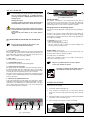
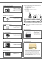
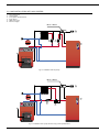
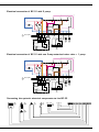
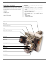
Installation, operating and
maintenance Instructions
N-Mini / N 1 / N 2 / N 3
excellence in hot water
07/09/2004 - 66401000
INDEX
INTRODUCTION
Who should read these instructions
Symbols
Applicable standards
Important notes
USER GUIDE
Use of the boiler
Setting the burner to safety mode
DESCRIPTION
General description
Operating principle
Design characteristics
Boiler views and key to parts
TECHNICAL CHARACTERISTICS
General
Operating condition limits
Dimensions
Hot water output data
General characteristics
2
2
2
2
2
3
3
3
4
4
4
4
4
5
5
5
5
5
5
BURNER CHARACTERISTICS
Description of the burner
Factory settings parameters
Burner dimension
COMMISSIONING
Filling the hot water and heating circuits
Using the boiler for the first time
MAINTENANCE
Recommendation
Boiler maintenance
Safety equipment maintenance
Draining the boiler
SPARE PARTS
Casings
Accessories
Electrical accessories
INSTALLATION
6
SERVICE RECORD
Boiler room
Chimney connections
Fuel oil supply
Heating connection
Hot water connection
Electrical connections
Control kit
N + NHR INSTALLATION WITH ACV CONTROL
6
6
6
7
7
8
9
10
Details of the installation
Service engineer’s report
12
12
13
13
14
14
14
14
14
14
14
14
15
15
15
15
16
16
16
1
INTRODUCTION
WHO SHOULD READ THESE INSTRUCTIONS
APPLICABLE STANDARDS
These instructions should be read by:
- the specifying engineer
- the installer
- the user
- the service engineer
The products described in this document have been certified at
European level (European Directive 92/42/EEC «Efficiency»). They
have also been awarded the Belgian “OPTIMAZ” LABEL (fuel oil
boiler).
SYMBOLS
The following symbols are used in these instructions:
Important instructions for correct operation of the
installation.
Essential instructions to ensure the safety of
persons and the environment.
IMPORTANT NOTES
These instructions are an integral part of the equipment to which
they relate and must be handed to the user.
The product must be installed and serviced by qualified engineers
in accordance with the regulations in force.
Danger of electrocution.
DANGER
ACV declines all liability for any damage caused as a result of
incorrect installation or in the event of the use of appliances or
accessories that are not specified by ACV.
Failure to follow the instructions describing the
test operations and procedures may cause injury to
persons or risks of environmental pollution.
N.B.:
ACV reserves the right to change the technical characteristics and
specification of its products without notice.
HOT
Danger of burning.
2
USER GUIDE
USE OF THE BOILER
Before carrying out any work on the boiler, isolate it
from the electrical supply at the switch on the external
control box.
Also place the main switch on the control panel to
“OFF”.
You should familiarise yourself with the control panel
(fig. 1)
The user must not attempt to gain access to the
components inside the control panel.
1. Control thermostat
When the boiler is used for heating only, the boiler temperature may
be set at 60 to 90°C. If the boiler is used to generate domestic hot
water and heating, the boiler’s control thermostat should be set at
80°C to ensure optimum operating conditions.
2. Main switch
Use this switch to turn the boiler on and off.
3. Summer/Winter switch
Use this switch to start and stop the heating pump.
75
90
°C
0
Starting the burner:
in normal operation the burner starts automatically if
the temperature of the boiler is below the set point.
1
15
To ensure that your system operates correctly, please
have it serviced annually by a qualified engineer;
servicing should be completed before the start of the
heating season.
30
60
45
3
fig. 2 : N-Mini Control panel
Pump operation:
The pump is controlled by a reset high limit thermostat, which is
located at the rear of the boiler. This is pre-set at 45°C. When the
boiler starts up, it delays the activation of the boiler pump, thereby
preventing any risk of corrosion in the combustion chamber.
Gauge pressure of the heating system
Your system must be fitted with a heating safety valve calibrated to
3 bars.
Ensure that the system is always under water pressure. When the
system is cold and the air inside it has been vented, the gauge
must indicate a pressure between 0.5 and 1.5 bar depending on
the height of the building.
To add water: (refer to Fig. 10 on Page 7)
• Open the filling valve (5).
• Close the valve properly after filling.
• Vent the system in order to obtain an accurate reading of the
pressure inside the heating circuit.
Safety valves
(heating circuit)
If water is found to be escaping from one of the safety valves, stop
the boiler and contact your installer for advice.
A monthly test is recommended:
Lift the lever on the drain cock for a few seconds to ensure that the
safety valve is working correctly.
If there is a problem after this short test, please
contact your installer for advice.
4. Thermostat-pressure gauge
This gauge shows the temperature of the boiler and the pressure in
the primary heating circuit. The temperature must not exceed 90°C.
If it rises above this point, turn off the boiler and check the settings
on the thermostat. If the problem persists, call a technician.
The pressure must not fall below 1 bar. If it does fall below this point,
look up the section entitled “Gauge pressure of the heating installation”
in this section below.
5. Manual reset high-limit thermostat
If the boiler temperature exceeds 103°C, this safety device will be
enabled. The boiler temperature must drop below 60°C to re-start.
Unscrew the cover and press the re-start key with a pen or an object
with a similar sharp point. Replace the cover. If the fault persists,
turn off the boiler and call a technician.
DANGER
The water escaping from the safety valve can
be extremely hot and cause serious burns.
HOT
BURNER SHUTDOWN
If the burner is not working:
1. The burner indicator lamp lights up.
2. Press the burner reset button (Fig. 3) on the burner. Turn the
boiler off for several seconds at the main switch, then restart the
boiler.
3. If the burner still does not work, rearm the manual reset highlimit
thermostat on the control panel (Fig. 4).
60
4. If the anomaly persists, please contact your installer.
90
2
3
3
fig. 1 : Control panel
1
5
fig. 3
fig. 4
3
DESCRIPTION
GENERAL DESCRIPTION
Casing
• Model N is a single boiler (heating).
The boiler is covered with a steel casing that has been stove enamelled
at 220°C after scouring and phosphating.
• Equipment required: a water connection kit for the heating circuit
supply (optional).
BOILER VIEWS AND KEY TO PARTS
• The N-Mini control panel includes a control thermostat and a
thermostat pressure gauge.
• The control panel on N 1 - 2 - 3 boilers includes a main switch,
a Summer/Winter switch, a thermostat pressure gauge, a control
thermostat and a manual reset high-limit thermostat.
• The N boiler can be connected directly to the chimney using a
B23 chimney connector.
• N-Mini Model: output of 16.6 kW.
• N1 Model: Outputs in the range 20 to 25 kW.
1.
2.
3.
4.
5.
6.
7.
8.
9.
10.
11.
12.
Top cover
Heating outlet
Heating return
Chimney connection
Heating circuit
Combustion chamber
Boiler drain cock
Fuel oil burner
Left-right removable burner chamber plate
Exchanger (flue ways)
Front panel
Control panel
• N2 Model: Outputs in the range 28 to 36 kW.
• N3 Model: Outputs in the range 36.5 to 51 kW.
1
2
3
OPERATING PRINCIPLE
12
Simple to control, safety assured
The temperature of the water in both the heating circuit and the hot
water circuit is regulated by a single control. This is achieved by
means of the control thermostat and the bulb is located beside the
boiler outlet. switch.
• A manual reset high-limit thermostat locks the burner if the
primary water temperature reaches 103°C.
• A minimum thermostat, fitted at the rear of the boiler, and preset
at 45°C, delays the activation of the boiler pump. This prevents
any risk of corrosion in the combustion chamber.
11
10
9
Generation of domestic hot water
Boiler N can be combined with the NHR tank (110 L) superimposed
with the boiler or with any other ACV tank.
DESIGN CHARACTERISTICS
Outer body
8
The outer body which holds the primary water is made from STW 22
heavy gauge steel.
Flue ways
The boiler’s flue ways can be accessed from the front and include
a set of removable turbulators, in either stainless steel or chrome,
which have been specially designed to provide the optimum
combustion efficiency.
Combustion chamber
The boiler features a large, water-cooled combustion chamber to
guarantee a good flame.
Removable burner chamber plate
The chamber plate is fitted on a hinge (left or right) and made from
STW 22 steel. It is protected from the flame by a ceramic fibre
padding and a vermiculite brick.
Insulation
The burner body is insulated with rock wool padding (50mm thick).
4
6
fig. 5
5
7
4
TECHNICAL CHARACTERISTICS
GENERAL
OPERATING CONDITION LIMITS
The appliances are supplied fully assembled, tested and packed
standing on a timber base with impact protection strips and wrapped
in heat-shrunk plastic film. When the appliance arrives, remove the
packaging and check that no parts have been damaged in transit.
Refer to the dimensions and weights listed below for handling
purposes:
Maximum service pressure (tank filled with water)
- Heating circuit: 3 bar
- Domestic hot water circuit : 10 bar (*)
Test pressure (tank filled with water)
- Heating circuit: 4,5 bar
- Domestic hot water circuit : 13 bar (*)
Operating temperature
- Maximum temperature: 90°C
(*) if the boiler is connected to a domestic hot water production tank.
DIMENSIONS
NHR (110L)
GG
CC
51
0
915
915
915
EE
FF
BB
ØD
ØD
470
AA
A mm
B mm
C mm
D Ø mm
E mm
F mm
G mm
N-Mini
370
565
N1
470
700
N2
470
N3
530
Kg (*)
495
80
425
357
187
62
566
130
550
445
260
108
765
566
130
615
510
260
122
805
656
150
645
550
260
157
(*) The weights shown are the drained weights.
DOMESTIC HOT WATER PERFORMANCE “N + NHR (110 L)”
N1
N2
Operating conditions at 85°C
Peak flow at 45°C (ΔT = 35°C)
L/10’
236
236
Peak flow at 60°C (ΔT = 50°C)
L/10’
145
145
GENERAL CHARACTERISTICS
Input
Output
Pressure loss of the flue gas circuit
N-Mini
N1
N2
N3
kW
18.4
22.0 / 28.0
30.4 / 40.0
40.0 / 57.0
kW
16.6
20.0 / 25.0
27.0 / 35.7
36.5 / 51.0
mbar
0.11
0.15
0.17
0.15
Heating circuit capacity
L
17
31
37
53
Heating connection (female)
Ø
3/4”
1”
1”
1” 1/4
5
INSTALLATION
BOILER ROOM
Important
• Never obstruct the ventilation.
• Do not store inflammable products in the boiler room.
• Avoid storing corrosive products such as paint, solvents, chlorine,
salt, soap or other cleaning products near the boiler.
A.
B.
C.
D.
E.
F.
High-level ventilation
Low-level ventilation
Draught stabiliser
Flame inspection window
Height of lined chimney
Chimney diameter
F
E
A
Accessibility
-
to the front
to the rear
to the sides
above
C
B
The boiler room should be big enough to allow easy access to the
boiler. Minimum clearances around the boiler (mm):
D
500
150
100
700
fig. 6 : Boiler ventilation and B23 chimney connector
Important note:
The above table is shown by way of indication only as
regulations vary from country to country.
Ventilation
The boiler room must have both low- and high-level ventilation
(see fig. 6).
For your information, the table below gives the minimum
ventilation requirements according to Belgian regulations.
The high output of our boilers means that the flue
gases are at a low temperature.
The attendant risk of condensation may cause damage
to some chimneys. To avoid this risk we strongly advise
that you line the chimney.
Please contact your installer for any further information.
The user must ensure that his boiler room ventilation complies
with local regulations.
Ventilation
N-Mini
N1
N2
N3
Fresh air supply min.
m3/h
33
50
72
102
High-level ventilation (A)
dm2
150
150
150
150
Low-level ventilation (B)
dm2
150
150
150
170
FUEL OIL SUPPLY
Single-pipe installation
Base
The base on which the boiler will be mounted must be made from
noncombustible materials.
(fig. 7)
Height H
Ø 8 mm
Ø 10 mm
0,5 m
L = 10 m
L = 20 m
1.0 m
L = 20 m
L = 40 m
1.5 m
L = 40 m
L = 80 m
2.0 m
L = 60 m
L = 100 m
CHIMNEY CONNECTIONS
Two-pipe installation
IMPORTANT
The boiler must be installed by a qualified engineer
in accordance with the local standards and codes of
practice.
The diameter of the chimney must not be less than the
diameter of the boiler’s chimney reducer.
Chimney connector type: B23
Height H
Ø 8 mm
Ø 10 mm
0m
L = 35 m
L = 100 m
0.5 m
L = 30 m
L = 100 m
1.0 m
L = 25 m
L = 100 m
1.5 m
L = 20 m
L = 90 m
2.0 m
L = 15 m
L = 70 m
3.0 m
L=8m
L = 30 m
3.5 m
L=6m
L = 20 m
L1
fig. 7
(fig.6)
The chimney must be connected to the boiler by means of a metal
pipe rising at an angle from the boiler to the chimney.
max 4m
H
max 4m
A chimney connector is required.
Chimney
(fig. 8)
N-Mini
N1
N2
N3
E = 5 m Ø min. F
mm
97
130
143
170
E = 10 m Ø min. F
mm
82
130
130
143
E = 15 m Ø min. F
mm
80
130
130
130
H
L1
H
L1
6
fig. 8
INSTALLATION
CONNECTING THE HEATING SYSTEM
HOT WATER CONNECTION
ACV water kit
ACV can supply an optional
pre-assembled water kit.
This kit comprises:
Pressure reducing valve
If the mains water pressure exceeds 6 bar, a pressure reducing
valve calibrated to 4.5 bar must be installed.
Safety group
• A pump;
• A 3-way manual valve. This
valve can be power-operated if
required;
• Connection pipes that can be
used to connect a second
heating circuit;
• Two isolating valves;
• Connectors for the right- or
efthand mounting of the
expansion vessel, the safety
valve with pressure gauge and
the fill valve.
The expansion vessel is not
included.
The safety group of the water tank must be approved by ACV and
calibrated to 7 bar; the group’s valve discharge must be connected
to the drain.
Hot water expansion vessel
Installing a hot water expansion vessel will prevent any risk of
excess pressure due to water hammer or pressure fluctuations.
Hot water circulation
If the water tank is a long way from the point of use,
installing a closed recirculation circuit can ensure a faster hot water
drawoff at any time.
fig. 9 : ACV water kit
Typical N + NHR domestic hot water connection (110 L)
with thermostat valve
Typical single-circuit connection
1.
2.
3.
4.
5.
6.
7.
8.
9.
1.
2.
3.
4.
5.
6.
7.
8.
9.
10.
11.
3-way power-operated mixer valve
Safety valve calibrated to 3 bar, with pressure gauge
Pump
Non-return valve
System filling valve
Expansion vessel
ACV 13.00 controller (see Controller Kit on page 9)
Heating system isolating valve
Drain cock
Safety group
Pressure reducing valve
Thermostatic mixer
Hot water pump
Non-return valve
Hot water expansion vessel
Cold water supply tap
Drawoff tap
Drain cock
Air vent
Isolating valve
4
8
11
5
2
3
10
8
8
7
5
6
1
4
3
7
2
1
5
6
9
9
fig. 11 : Hot water system connection
fig. 10 : Heating system connection
Drain
DANGER
HOT
IMPORTANT
As a safety measure, we strongly advise the
installation of a thermostatic mixer to prevent
any risk of burning to persons.
The drain cock and safety valve must be connected to the building
drain.
7
230V-50 Hz
6A
INSTALLATION
N-Mini
B
Optional accessories
Ø 3/4“
Ø 3/4”
Expansion vessel
5 litres
6
M
Or
Br
Thermostatic mixer
Bk
Br
Ø 3/4”
Pressure reducing valve
B
Safety group
3
Bk
B
t
ELECTRICAL CONNECTIONS
Power supply principle
Or
5
t
4
t
G
The boiler operates on a single-phase supply of 230 V/50 Hz.
You should install a control box with main switch and 6A fuses
externally to the boiler to allow the boiler to be isolated from the supply
for servicing and repairs.
B
The installation must comply with your local standards and codes of
practice.
R
G
Statutory compliance
S3 T2 T1 N
L1
Safety
The stainless steel if present water tank must be provided with a
separate earth.
L1
4
B
W
5
2
C
Or
1
B
R
G
G
W
Or
Bk
R
B
1
Y/Gr
L1
N T1 T2 S3 B4
230V-50 Hz
6A
B
R
N T1 T2 S3 B4
Br
L1
B
Blue
Black
Brown
Grey
Orange
Red
White
Yellow/Green
Y/Gr
Br
B.
Bk.
Br.
G.
Or.
R.
W.
Y/Gr.
2
C
Y/Gr
Wiring diagram key
2
1
3
Or
Main switch
Summer/Winter switch Thermal reset high-limit thermostat (95°C)
Control thermostat (60/90°C)
Manual reset high-limit thermostat (103°C max.)
Minimum thermostat 45°C (T.O.D)
Pump (optional)
Room thermostat
Y/Gr
Br
Electrical wiring of N boilers
1.
2.
3.
4.
5.
6.
7.
N
Bk
The boiler must be isolated from the electrical supply
before any work is carried out on it.
N1
N2
N3
7
6
8
INSTALLATION
CONTROL KITS (OPTIONAL)
ACV 13 electrical controller
• Direct control of the burner
(ON/OFF) or modulating
control of a power-operated
valve.
• Domestic hot water priority.
Electrical wiring diagram of the wall-mounted case
B2.
B9.
B5.
P1.
Y1/Y2/N.
bl.
n/z.
br.
Temperature sensor
Outdoor sensor
Analogue/digital room sensor
Pump
Servomotor (SQK 349 or SSY 319)
Blue N
Black Y2
Brown Y1
SQK 349
P1
QAD 22 heating outlet sensor
• For configuration with an air
temperature controller.
B9
B3
B2
QAD22
bl bk br
20
19
18
17
16
15
14
13
12
11
10
20
19
18
17
16
15
14
13
12
11
10
N Y2 Y1
QAC 32 Outdoor sensor
B5
QAAD50
(QAAD70) QAC32
P1
9
8
9
8
B5
7
6
7
6
B9
5
4
5
4
3
2
3
2
B3
1
1
B2
Please contact your installer if you require any further
information.
• For configuration with an air
temperature controller.
Boiler Control BC 01
• This control box is used
to connect a single- or
dualfuel boiler to a
heating system boiler,
without hotwater priority.
SSY 319 servomotor
• SSY 319 electromechanical
servomotor for 3-way valves.
Boiler Control BC 03
SQK 349 servomotor
• SQK 349 electromechanical
servomotor for 3-way valves.
• The Boiler Control BC 03 controls a heating system boiler
without domestic hot water priority with a boiler: it controls
the burner operation, the heating pump and the boiler either through the SCE pump or the 3-way SCE valve.
Wall-mounted case
• ACV 13 connecting
wiring case.
• The Boiler Control BC 03 incorporates a pump anti-lock
device that regularly starts up the pump for a few seconds
after a long period of non-use.
9
INSTALLATION
N + NHR INSTALLATION WITH ACV CONTROL
1.
2.
3.
4.
5.
6.
Room thermostat
Heating pump
3-way power-operated valves
Boiler burner
NHR 110 L boiler
Electrical supply
BC 01 or BC 03
1
2
3
5
4
fig. 12 : Installation with two pumps.
BC 01 or BC 03
1
5
2
3
4
fig. 13 : Installation with 1 pump and one 3-way power-operated valve.
10
INSTALLATION
Electrical connection of BC 01 with 2 pump
1
3
1
6
2
3
4
5
6
7
8
11
9
4
6
8
7
5
9 10 11 12 13 14 15 16 17 18 19 20
230 V 50Hz
t
T8 T7 T6 B5
1
T8 T7 T6 B5
5
3
L1
C
2
N T1 T2 S3
4
t
Electrical connection of BC 01 with one 3-way motorised mixer valve + 1 pump
1
3
1
6
2
3
4
5
6
7
8
11
9
4
6
8
7
5
9 10 11 12 13 14 15 16 17 18 19 20
230 V 50Hz
T8 T7 T6 B5
t
1
T8 T7 T6 B5
5
2
3
L1
C
N T1 T2 S3
4
t
Connecting the system’s electrical components to the BC 03
1
3
2
4
230 V ~ 50 Hz
N
L
PE PE PE
1
2
3
4
5
6
7
8
9
10 11
6
3
11
BURNER CHARACTERISTICS
DESCRIPTION OF THE BURNER
This new generation of fuel oil burners comply with current
requirements in terms of performance and the cleanliness of
combustion gases.
The burner is fitted with the finest quality components reflecting the
latest developments in technology and the fuel-oil is pre-heated.
Components:
• “Landis & Gyr” relay
• “A.E.G.” motor
• “Suntec” pump
• “May & Christe” transformer
• “Danfoss” fuel-oil preheater
Throat
Burner socket
Nozzle line adjuster screw
Louver
Pump - nozzle connection pipe
Control relay
Burner reset
High voltage transformer
Motor
Electrical valve
Fuel oil pump
Motor capacitor
12
Advantages
• Simple to install, it is fitted with a safety switch and a new burner
suspension system.
• A special key is provided with the burner for any maintenance
work needed.
• The burner air pressure adapts to the pressure in the combustion
chamber.
• An automatic stop check valve stops the airflow when the boiler is
turned off, preventing it from cooling.
• Silent and very reliable operation.
• Adapts to the depth of the boiler with the adjustable nozzle
clamp.
• Three air-regulation points to ensure the optimum air/fuel oil
mixture.
- The air is pre-regulated upstream;
- primary regulation;
- combustion head regulation.
BURNER CHARACTERISTICS
REGULATION PARAMENTER
BM R 31
Power
Electrical power
Nozzle
N1
N2
N3
kW
23.0
30.0
49.0
W
150
150
150
gal/h
0.50
0.75
1.25
60°
60°
60°
Kg/h
1.94
2.53
4.13
bar
13.5
10.5
10
0.6
0.6
0.6
3
4.5
4
Nozzle angle
Fuel oil rate of flow
Pump pressure
Flue gas index
Louver regulation
Combustion head regulation
Kg
Weight
2
1
2
12
12
12
fig. 15 :
Combustion head
adjuster screw
fig. 14 :
Electrode distance
BURNER DIMENSION
BM R 51
fig. 16 :
Air flow adjuster screw
(fine tuning)
A mm
B mm
C mm
D mm
E mm
F mm
G Ø mm
L Ø mm
LK Ø mm
BM R 31
240
270
215
280
60-130
M8
80
85
140-165
BM R 51
240
270
215
280
60-130
M8
80
85
140-165
fig. 17
fig. 18
fig. 19
13
COMMISSIONING
MAINTENANCE
FILLING THE HEATING CIRCUIT
RECOMMENDATION
It is compulsory to have the boiler serviced once a year. Boiler
servicing and checking must be carried out by a qualified engineer.
IMPORTANT
If your “N” boiler is connected to an ACV tank, it is
essential to fill the domestic water circuit before the
heating circuit.
1. Open valves 5 and 8 to fill the heating circuit and make sure the
pressure does not exceed 2 bars.
8
8
MAINTAINING THE BOILER
1. Isolate the boiler from the electrical supply at the switch on the
external control box and close the fuel oil supply valve.
2. Place the main switch on the control panel to “OFF” (except for the
N-Mini).
3. Remove the boiler front panel (1) (except for the N-Mini).
4. Loosen the two nuts or locking clamps for the N-Mini to open the
burner chamber plate (2).
5. Remove the insulating brick (for the N-Mini only).
6. Remove the stainless-steel turbulators (3).
7. Brush the flue ways, clean the chamber and vacuum up any soot
deposits.
8. Check the insulation of the burner chamber plate (4).
9. Before reassembling, clean the burner combustion head (5).
10. Check that the thermostats and safety valves are working
correctly.
4
4
3
7
2
2
1
1
5
3
6
5
9
fig. 21
fig. 20
MAINTENANCE OF SAFETY EQUIPMENT
2. Vent the system.
- Check that all thermostats and safety devicesoperate correctly: the
boiler thermostat and the manual reset high-limit thermostat (103°C).
- Check the heating circuit safety valves.
3. Once you have vented the system, return the pressure to the
static pressure plus 0.5 bar.
DRAINING THE BOILER
Height of the heating system:
• 10 m ➠ heating circuit pressure = 1.5 bar
• 15 m ➠ heating circuit pressure = 2 bar
USING THE BOILER FOR THE FIRST TIME
1. Check the fuel oil supply connection and ensure that it is free
from leaks.
2. Check the electrical connection to the boiler and the boiler room
ventilation, and ensure that the flue gas discharge pipes and the
burner chamber plate are properly gas tight.
3. Set the boiler thermostat to between 60° and 90°C.
4. Place the Summer/Winter switch to the required position.
5. Place the main switch to “ON”.
6. Carry out the necessary venting operations, measurements and
settings.
14
DANGER
HOT
The water draining from the drain cock is
very hot and can cause serious burns.
Keep all persons away from running
hot water.
Draining the heating circuit
(fig. 20)
1. Place the main switch on the control panel to “OFF”, isolate the
boiler from the electrical power supply at the switch in the external
control box.
2. Close the isolating valves (8) in the heating circuit.
3. Connect a flexible tube to the drain cock (9).
4. Open the drain cock (9) to drain the heating circuit.
SPARE PARTS
N°
CASINGS
N-MINI
N1
N2
N3
A01
Right side
21471387
21471380
21471381
21471382
A02
Left side
21472387
21472380
21472381
21472382
A03
Front panel
-
21473380
21473381
21473382
A04
Rear panel
21474387
21474380
21474381
21474382
A05
Top cover
21475387
21475380
21475380
21475382
A06
Unequipped control panel
21477387
21477380
21477380
21477382
A07
Front bridge
21473387
-
-
-
N°
ACCESSORIES
B01
Unequipped body
30465160
30465153
30465154
30465155
B02
Burner chamber plate
2147P371
2147P380
2147P381
2147P382
B03
brick backplate
-
2147E380
2147E381
2147E382
B04
Burner chamber plate insulating brick
51701000
51404028
51404029
51404030
B05
Door ceramic fibre insulating cord
-
51401113
51401113
51401113
B06
Burner chamber insulating cover
-
51401127
51401128
51401129
B07
Pressure gauge thermometer
54763009
54441008
54441008
54441008
B08
Drain cock, Ø 1/2”
55426001
55426001
55426001
B09
M 10 19x33mm hinge pin
-
47405252
47405252
47405252
B10
Probe attachment spring
47438008
47438008
47438008
47438008
B11
Turbulators
50423098
50423097
50423097
50423098
B12
H.D.P.E. handle
-
49410280
49410280
49410280
B13
Flame inspection window
50423008
50423008
50423008
50423008
B14
Grommet
54428001
54428001
54428001
54428001
B15
Brass pocket, Ø 1/2” / L. 100 mm
63438001
63438001
63438001
63438001
B16
Control panel self-adhesive
-
617G0050
617G0050
617G0050
B17
Burner chamber plate insulation
51700033
-
-
-
B18
Door locking clamp
47405137
-
-
-
B19
Male/female brass chimney reducer, Ø 1/2” x 1/4”
43416065
43416065
43416065
43416065
B20
Clip retainer
47405004
47405004
47405004
47405004
B21
Stud
47405005
47405005
47405005
47405005
N°
ELECTRICAL ACCESSORIES
C01
Full control panel
-
24614108
24614108
24614109
C02
ON/OFF switch
-
54428116
54428116
54428116
C03
Summer/Winter switch
-
54428107
54428107
54428107
C04
90°C control thermostat
54442045
54442045
54442045
54442045
C05
Manual reset high-limit thermostat (103°C)
54442015
54764009
54764009
54764009
C06
Thermal reset high-limit thermostat (45°C)
54442027
54442027
54442027
54442027
C07
Wiring
25435217
-
-
-
15
SERVICE RECORD
DETAILS OF THE INSTALLATION
Installation date:
Model:
% CO2 (max. load) :
Serial number:
Flue gas T°:
Heating system pressure setting:
Efficiency:
Name and signature:
Fuel oil pressure:
SERVICE NOTES
Installation date:
Comments:
% CO2 (max. load) :
Flue gas T°:
Efficiency:
Name and signature:
Fuel oil pressure:
Installation date:
Comments:
% CO2 (max. load) :
Flue gas T°:
Efficiency:
Name and signature:
Fuel oil pressure:
Installation date:
Comments:
% CO2 (max. load) :
Flue gas T°:
Efficiency:
Name and signature:
Fuel oil pressure:
Installation date:
Comments:
% CO2 (max. load) :
Flue gas T°:
Efficiency:
Name and signature:
Fuel oil pressure:
Installation date:
Comments:
% CO2 (max. load) :
Flue gas T°:
Efficiency:
Fuel oil pressure:
16
Name and signature:
excellence in hot water
INTERNATIONAL
FRANCE
SLOVAK REPUBLIC
BELGIUM
ITALIA
ACV ITALIA
VIA PANA 92
I-48018 FAENZA (RA) - ITALIA
TEL.:+39 0546 64 61 44
FAX:+39 0546 64 61 50
E-MAIL: [email protected]
SLOVENIA
ACV BELGIUM nv/sa
KERKPLEIN, 39
B-1601 RUISBROEK-BELGIUM
TEL.: +32 2 334 82 40
FAX: +32 2 334 82 59
E-MAIL: [email protected]
CHILE
NEDERLAND
ACV NEDERLAND bv
POSTBUS 350
NL-2980 AJ RIDDERKERK - NEDERLAND
TEL.:+31 180 42 10 55
FAX:+31 180 41 58 02
E-MAIL: [email protected]
UK
ALBIN TROTTER Y ACV LTDA
SAN PABLO 3800
QUINTA NORMAL - SANTIAGO - CHILE
TEL.:+56 2 772 01 69
FAX:+56 2 772 92 62/63
E-MAIL: [email protected]
CZECH REPUBLIC
POLAND
ACV POLSKA sp. z.o.o.
UL.WITOSA 3
87 - 800 WŁOCŁAWEK - POLAND
TEL.:+48 54 412 56 00
FAX:+48 54 412 56 01
E-MAIL: [email protected]
USA
ACV CR SPOL. s.r.o
NA KRECKU 365
CR-109 04 PRAHA 10 - CZECH REPUBLIC
TEL.:+420 2 720 83 341
FAX:+420 2 720 83 343
E-MAIL: [email protected]
DEUTSCHLAND
PORTUGAL
www.acv-world.com
ACV international n.v
KERKPLEIN, 39
B-1601 RUISBROEK - BELGIUM
TEL.: +32 2 334 82 20
FAX: +32 2 378 16 49
E-MAIL: [email protected]
ACV WÄRMETECHNIK GMBH & CO KG
GEWERBEGEBIET GARTENSTRASSE
D-08132 MÜLSEN OT ST. JACOB - DEUTSCHLAND
TEL.:+49 37601 311 30
FAX:+49 37601 311 31
E-MAIL: [email protected]
ESPAÑA
ACV ESPAÑA
C/DE LA TEIXIDORA, 76
POL. IND. LES HORTES
E-08302 MATARÓ - ESPANA
TEL.:+34 93 759 54 51
FAX:+34 93 759 34 98
E-MAIL: [email protected]
ACV FRANCE sa
31, RUE AMPERE - Z.I MI - PLAINE
F-69680 CHASSIEU - FRANCE
TEL.:+33 4 72 47 07 76
FAX:+33 4 72 47 08 72
E-MAIL: [email protected]
ACV SLOVAKIA s.r.o.
PLUHOVÁ 49
831 04 BRATISLAVA - SLOVAK REPUBLIC
TEL.:+421 2 444 62 276
FAX:+421 2 444 62 275
E-MAIL: [email protected]
ACV D.O.O. SLOVENIA
OPEKARNA 22b
1420 TRBOVLJE - SLOVENIA
TEL.:+386 356 32 830
FAX:+ 386 356 32 831
E-MAIL: [email protected]
ACV UK Ltd
ST. DAVID’S BUSINESS PARK
DALGETY BAY - FIFE - KY11 9PF
TEL.:+44 1383 82 01 00
FAX:+44 1383 82 01 80
E-MAIL: [email protected]
TRIANGLE TUBE PHASE III
FREEWAY CENTER - 1 TRIANGLE LANE
BLACKWOOD NJ 08012 - USA
TEL.:+1 856 228 8881
FAX:+1 856 228 3584
E-MAIL: [email protected]
BOILERNOX LDA
RUA OUTEIRO DO POMAR
CASAL DO CEGO, FRACÇÃO C,
PAVILHÃO 3 - MARRAZES
2400-402 LEIRIA - PORTUGAL
TEL.:+351 244 837 239/40
FAX:+351 244 823 758
E-MAIL: [email protected]
RUSSIA
ACV RUSSIA
1/9, MALYI KISELNYI
103031 MOSCOW - RUSSIA
TEL.:+7 095 928 48 02 / +7 095 921 89 79
FAX:+7 095 928 08 77
E-MAIL: [email protected]
ARGENTINA
DENMARK
NEW ZEALAND
AUSTRALIA
ESTONIA
ÖSTERREICH
GREECE
ROMANIA
TECNOPRACTICA
ALFEREZ BOUCHARD 4857
1605 CARAPACHAY - BUENOS AIRES
TEL.: +54 11 47 65 33 35
FAX: +54 11 47 65 43 07
E-MAIL: [email protected]
HUNT HEATING PTY LTD
10 GARDEN BOULEVARD
3172 VICTORIA - AUSTRALIA
TEL.: +61 3 9558 7077
FAX: +61 3 9558 7027
E-MAIL: [email protected]
BRAZIL
SIMETAL INDUSTRIA E COMERCIO
DE FERRAMENTAS LTDA
RUA GERSON ANDREIS 535
95112 - 130 CAXIAS DO SUL - BRAZIL
TEL.: +55 54 227 12 44
FAX: +55 54 227 12 26
E-MAIL: [email protected]
BULGARIA
PROXIMUS ENGINEERING LTD
7 BIAL KREM STR.
9010 VARNA - BULGARIA
TEL.:+359 52 500 070
FAX:+359 52 301 131
E-MAIL: [email protected]
CHINA
BEIJING HUADIAN HT POWER TECHNOLOGY
DEVELOPMENT CO. LTD
ROOM B-912, TOWER B, COFCO PLAZA
N°. 8, JIANGUOMENNEI AVENUE
BEIJING 100005 - PEOPLE’S REPUBLIC OF CHINA
TEL.:+86 10 652 30 363/393 EXT 101
FAX:+86 10 652 27 071
E-MAIL: [email protected]
SHANGHAI COOLTECH LTD
14/F E. CHINA MERCHANTS PLAZA
N°. 333 CHENGDU ROAD (N)
200041 SHANGHAI - CHINA
TEL.:+86 21 52 98 11 22 - 820
FAX:+86 21 52 98 13 58
E-MAIL: [email protected]
VARMEHUSET
FRICHSVEJ 40 A
8600 SILKEBORG - DENMARK
TEL.:+45 86 82 63 55
FAX:+45 86 82 65 03
E-MAIL: [email protected]
TERMOX AS
TAHE 112A
51013 TARTU - ESTONIA
TEL.:+372 736 73 39
FAX:+372 736 73 44
E-MAIL: [email protected]
ESTIAS
MARASLI STREET 7
54248 THESSALONIKI - GREECE
TEL.:+30 23 10 31 98 77 / +30 23 10 32 03 58
FAX:+30 23 10 31 97 22
E-MAIL: [email protected]
ÎLE MAURICE
ENERGY PRODUCTS INTERNATIONAL
8/10 BELFAST PLACE
PO BOX 15058 HAMILTON - NEW ZEALAND
TEL.:+64 7 847 27 05
FAX:+64 7 847 42 22
E-MAIL: [email protected]
PROTHERM HEIZUNGSTECHNIK Gmbh
TRAUNUFERSTRASSE 113
4052 ANSFELDEN - ÖSTERREICH
TEL.:+43 7229 804 82
FAX:+43 7229 804 92
E-MAIL: [email protected]
SC TRUST EURO THERM SA
D.N PIATRA NEAMT - ROMAN
km 2 C.P 5 O.P 3 jud. Neamt
5600 PIATRA NEAMT - ROMANIA
TEL.:+40 233 20 62 06
FAX:+40 233 20 62 00
E-MAIL: [email protected]
SOTRATECH
29, RUE MELDRUM
BEAU BASSIN - ÎLE MAURICE
TEL.:+230 46 76 970
FAX:+230 46 76 971
E-MAIL: [email protected]
TUNISIE
LITHUANIA
UKRAINE
UAB “GILIUS IR KO”
SAVARNORIU PR. 192
3000 KAUNAS - LITHUANIA
TEL.:+370 37 308 930
FAX:+370 37 308 932
MAROC
CASATHERM
PLACE EL YASSIR
20300 CASABLANCA - MAROC
TEL.:+212 22 40 15 23
FAX:+212 22 24 04 86
SO.CO.ME CHAUMAX
BOÎTE POSTALE N°44
1002 TUNIS - TUNISIE
TEL.:+216 71 78 15 91
FAX:+216 71 78 87 31
UKRTEPLOSERVICE LTD
PR. LAGUTENKO 14
83086 DONETSK - UKRAINE
TEL.:+38 062 382 60 47/48
FAX:+38 062 335 16 89