1
Sears l
OWNERS
MANUAL
MODEL NO.
917,253724
Caution:
Read Rules for
Safe Operation
and Instructions
Carefully
GARDEN TRACTOR
Assembly
Installation
Operation
Repair Parts
Sears, Roebuck and Co., Chicago, III. 60684 U.S.A.
CONGRATULATIONS
GTV 16 HP. Garden
MODEL
NUMBER
SERIAL
NUMBER
THE MODEL AND SERIAL NUMBERS WILL
BE FOUND ON THE MODEL PLATE ATTACHED TO THE TOP RIGHT SIDE OF DRAWBAR
{REFER TO PAGE 16).
on your purchase of a Sears Varidrive
Tractor_
It has been designed, engineered
and manufactured
to give you dependability
and performance
Should
you experience
any problem
you cannot easily remedy, pfease contact your nearest Sears, Roebuck and Co. store
They have competent,
well-trained
technicians
and the proper
tools and parts to service or repair this unit.
Please read and retain
this manual,
The instructions
wilt enable
YOU SHOULD RECORD BOTH MODEL AND
SERIAL NUMBERS AND KEEP IN A SAFE
PLACE FOR FUTURE REFERENCE,
you to assemble, operate and manta n your Tractor
properly.
Always observe the "RULES
FOR SAFE OPERATION".
YOUR
NEW
GARDEN
GTV
IG
TRACTOR
FEATURES
...
CRAFTSMAN
16 H,P° ENGINE-°cool-running performance
and long life w_th plenty of power to take on a variety of
yard, gardening or snow removal tasks.
CONTROL PANEL-with
Throttle, Choke, Light Switch, Ignition Switch, Ammeter and Parking Brake Lever-conveniently grouped for ease of user
INTERLOCK SWITCH SYSTEM-allows engine to start only
when tractor Clutch-Brake Pedal is depressed and Attachment
Clutch Lever is in "OFF" pos{tiono
ATTACHMENT
VERSATILITY-handles
a large variety of
Sears Yard and Garden Tractor Attachments including . . ,
MANUAL OR ELECTRIC LIFT.
44 INCH MOWER with three "high-lift"
blades to stand
grassup for level cuts.
SELF POWERED ROTO TILLER prepares soil for new
Eawnsand gardens with a 30 inch wide tilling path,,
OTHER SOIL TILLAGE ATTACHMENTS
including Plow,
Disc Harrow, D rag Harrow and Cultivator_
CHEVRON TIRES for added t;action in loose soil, gravel
ALL GEAR TRANSMISSION-three
speeds forward,
plus
reverse to let you select the proper match for the terra{n and
the job Automotive-type
differential helps guard against turf
scuffing
VARIDR!VE
SPEED CONTROL-is
especially
valuable when
load is not uniform
When
_ngineodriven
attachments
are
overloaded,
such as with heavy lawn mowing
or deep snow
throwing,
Lever to
operate
the ground
relieve the
or
speed may be reduced with the Control
load wh_le the attachment
continues
to
at fun speed
FULL
ONE
ON ELECTRnC
YEAR
START
snow,.
46 INCH DOZER BLADE levels or moves dirt and gravel or
removes snow.
42 INCH SNOW BLOWER handles wet, heavy powdery
snow with ease.
REAR GRADER
AND LEVELER
BLADE levels new
yards, grading lanes, drive ways and parking areas.,
WARRANTY
GARDEN
TRACTOR
For one year from the date of purchase, when this Garden Tractor is used for personal household purposes, Sears will
repair any defect in material or workmanship in this Garden Tractor, except the battery, at no charge.
If this Garden Tractor
purchase°
is used for commercial or rent{_l purposes, this warranty applies for only 30 days from the date of
FULL
90-DAY
WARRANTY
ON
BATTERY
For 90 days from the date of purchase, if any battery included with the Garden Tractor proves defective in material or
workmanship and will not hold a charge, Searswill replace the battery, at no charge=
LOMgTED
WARRANTY
ON
BATTERY
From the 91st day until one year from the date of purchase, if any battery inctuded with the Garden Tractor proves defec.,
rive in material or workmanship and will not hold a charge, Sears w_ll replace the battery, charging 1/12th of the price of
the new battery for each full month from the date of pumhase.
Warranty service is available at your home, at no charge, by simply contacting the nearest Sears store or Service Center
throughout the United States.
This warranty givesyou specific legal rights, and you may also have other rights which vary from state to state,
Sears, Roebuck and Cot
Sears Tower
BSC 4 t-3
Chicago, IL 60684
TABLE
RULES
FOR SAFE OPERATION
ASSEMBLY
OPERATION
INSTRUCTIONS
........
INSTRUCTIONS
controls
MANUAL
and how
BELOW
.................
................
RULES
1_ Know the
OWNER'S
OF CONTENTS
to stop
quickly,
FOR
READ
2
TROUBLE
4
REPAIR
SAFE
23.
THE
2o Do not allow children
to operate the vehicle.
Do not allow
adults to operate
it without
proper
instruction
or without having read the owners manual,
3. Do not carry passengers, Keep children
and pets a safe distance away,
4, Always wear substantial
footwear,
Do not wear loose fitting
clothing
that could get caught in moving parts,
5, Keep your eyes and mind on your tractor,
mower and the
area being cut, Don't let other interests distract you,
6o Do not attempt
to operate your tractor
or mower when
not in the drivers seat.
7. Always
get on or off your tractor
from the operators left
hand side,
8, Clear the work area of objects which might be picked up
and thrown.
9, Disengage ali attachment
clutches and return speed control
lever to neutral before attempting
to start the engine,
10, Disengage
power
to att#chments
and stop the engine before leaving the operator's
position°
1 t Disengage power to mower,
stop the engine and disconnect
spark plug wire(s) from spark plug(s) before cleaning, making an adjustment
or repairs,
12, Disengage power
to attachments
when transporting
or not
in use°
13. Take all possible precautions
when leaving the vehlcte unattended,
such as disengaging
the power-take-off,
lowering
the attachments,
returning
drive control
lever to neutral,
sh_fting into neutral,
setting
the parking
brake, stopping
the engine and removing the key,
14_ Do not stop or start suddenly
when going uphill or downhilt.
Mow up and down the face of slopes (not greater than
15°); never across the face,
15.
16.
17,
I8,
19.
20_
21,
224
MAINTENANCE
Reduce speed on slopes and make turns gradually
to prevent tipping
or loss of control,
Exercise extreme
caution
when changing dfrection
on slopes,
While going up or down slopes choose Ist gear to negotiate
the slope without
stopping
To reduce speed, move Vaddrive Control
Lever rearward to slower position,,
Never mow in wet or slippery
grass, when traction
is unsure or at a speed which could cause a skid,
Stay alert for holes in the terrain and other hidden hazards.
Do not drive too close to creeks, ditches and public
highways.
Exercise
special care when mowing
around fixed objects
in order to prevent
the blades from striking
them. Never
deliberately
run tractor
or mower
into or over any foreign
object,.
Never shift gears until tractor comes to a stop,
Never place hands or feet under the mower,
in discharge
chute or near any moving parts while tractor or mower are
running.
Always keep clear of discharge chute°
INSTRUCTIONS
SHOOTING
..............
.....................
PARTS ...........................
6
13
15
OPERATmON
Use care when pulling loads or using heavy equipment
a, Use only approved
drawbar hitch points,
b, Limit loads to those you can safety control.
c° Do not turn sharply, Use care when backing,,
d. Use counterweight
or wheel weights when suggested
the owner's manual.
in
24, Watch out for traffic when crossing or near roadways.
25, When
using any attachments,
never direct
discharge
of
material
toward
bystanders
nor atlow anyone near the vehicle while in operation.
26. Handte gasoline with care - it is highly flammable.
ao Use approved gasoline containers.
b, Never remove the cap of the fuel tank or add gasoline to
a running
or hot engine, or fill the fuel tank indoors°
Wipe up spilled gasoline
c, Open doors if the engine is run in the garage - exhaust
fumes
are dangerous,
Do not run the engine indoors,
27, Keep the vehicle and attachments
in good operating
condition,
and keep safety devices in place_
28. Keep all nuts, bolts and screws tight to be sure the equipment is in safe working
condition,
29, Never store the equipment
with gasoline in the tank inside
a building
where fumes may reach an open flame or spark.
Allow the engine to cool before storing in any enclosure,
30. To reduce fire hazard, keep the engine free of grass, leaves
or excessive grease, Do not clean product
while engine is
running.
31, Except
for adjustment;
DO NOT
operate
Engine if air
cleaner
or cover directly
over carburetor
air intake
is removed. Removal of such part could create a fire hazard,
32° DO NOT OPERATE
WITHOUT
A MUFFLER
OR TAMPER WITH THE EXHAUST
SYSTEM
Damaged mufflers
or spark arresters could create a fire hazard
Inspect periodically and replace if necessary,
33, The vehicle
and attachments
should
be stopped
and inspected for damage after striking
a foreign
object, and the
damage should
be repaired before restarting
and operating
the equipment,
34 Do not change the engine governor
settings or overspeed
the engine; severe damage or injury may result_
35 When using the vehicle with
mower,
proceed
as follows:
a_,Mow only in daylight
or in good artificial
light,,
b, Never make a cutting height adjustment
while the engine
is running if the operator must dismount
to do so.
c_ Shut the engine off when removing
the grass catcher or
unclogging
chute.
do Check the blade mounting
bolts for proper tightness
at
frequent
intervals.
36 Check the grass catcher bags frequently
for wear or deterioration,
Replace with new bags for safety protection.
37_ Do not operate the mower without
the entire grass catcher,
on mowers so equipped,
or the deflector
shield in place,
38 Disengage power to mower before backing up Do not mow
in reverse unless absolutely
necessary
and then only after
careful observation
of the entire area behind the mower.
LOOK FOR THIS SYMBOL TO POINT OUT IMPORTANT
SAFETY PRECAUTION&
IT MEANS - ATTENTION!
BECOME ALERT! YOUR SAFETY IS INVOLVED.
WARNING
This unit is equipped
with an internal combustion
engine and should not be used on or near any unimproved
forest-covered,
brushcovered or grass-covered
land unless the engine's exhaust system is equipped with a spark arrester meeting applicable
1ocaf or state
laws (if any), If a spark arrester is used, it should be maintained
in effective
worldng order by the operator
In the State of California
have similar laws., Federal
674A380.
the above is required
by law (Section
laws apply on federat fands, See your
4442 of the California
Public Resources Code). Other states may
AuthorSzed
Service Center for spark arrester muffler
part number
To assemble and adjust your Tractor you will need:
one 3/4"
socket, two 7/16"
wrenches and one
11/16" wrench
CAUTION:
DO NOT OPERATE VARIDRIVE
CONTROL
(FIG. 11) UNLESS ENGINE IS RUNNING, DAMAGE MAY
OCCUR TO VARIDRIVE
SYSTEM,
CUT AWAY
NOTE: RIGHT HAND (R,H_) AND LEFT HAND (L°H.} ARE
DETERMINED
FROM OPERATOR'S
POSITION WHILE
SEATED ON TRACTOR,
VIEW
_._
VENT CAP
L_.-_J
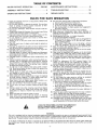
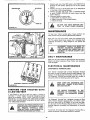
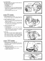
ASSElVtIaLY
1, Remove Shipping Strap Banding, Bundling Wires, Battery,
Steering Wheel and Bag of Parts. Also there is a Hold Down
Rod (shown below) hotding front end of tractor to wood
crate Remove Lag Screw from Hold Down Rod and wood
crate, Discard Rod and Screw,
BATTERY
TUBE
BATTERY
CELL
2. Fill and charge Battery (before installing).
DETAILED
INSTRUCTIONS
PACKAGED
TERY,
_!_
NOTE: SEE
WITH BAT-
WEAR EYE AND FACE SHIELD"
j
ao Fill Battery with electrolyte to bottoms of tubes in cells
(Fig. 1). NOTE: DO NOT OVERFILL. OVERFILLING
WILL RESULT IN DAMAGE TO TRACTOR.
WING NUT _._I_
ATELY IF ACCIDENTALLY
WITH ELECTROLYTE,
_'- FLAT WASHER
_._f"-,...,.----_ BATTERY
J/iT-,
WING NUT__
FLATWASHER--/7_/f!/-_-_'r-
ROD
_-i
IN CONTACT
b. Check level of electrolyte after 30 minutes. Add additional electrolyte if necessary, NOTE: TIGHTEN VENT
CAPS SECURELY°
c, Charge Battery at a rate not exceeding three amperes
for about two and one half hours,
k_
I" _
ED
ELECTROLYTE
AREFROM
EXPLOSIVE.
DO NOT
SMOKE, FUMES
CHARG-
d, Neutralize excess electrolyte for disposal by adding it
to four inches of water in a five gallon plastic container. Stir with a wooden or plastic paddle while adding
baking soda until the addition of more soda causes no
more foaming.
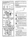
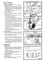
3. Install Battery using:
Battery Rod, two Wing Nuts, two Flat Washers, two Bah
tery Bolts,
NEGATIVE
BLACK
_
._"7
GROUND _
_,'_,a f,_\
CAR E..-..
_
_//
//,
_'_
:
F,GURE%.'&
iI ¥ Xi /N ..........
_2"
two Flat Washers, two Lockwashers, two Hex Bolts and
two Hex Nuts found in Bag of Parts.
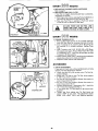
ao Lift Hood from rear sides (Fig, 2).
bo Remove tape from Plastic Tray_ Make sure Drain Tube
(Fig. 3) is fastened to Drain Hole in Battery Tray and
Battery Tray is positioned in hole of Battery Support.
co Piece Battery in Plastic Tray (Batten/Terminals to front
of Tractor) (Fig. 3)_
NOTE:
TIGHTEN
WING NUTS SECURELY
USING
YOUR THUMB
AND FOREFINGER.
DO NOT USE
TOOLS - OVER TIGHTENING
MAY OVERSTRESS OR
CRACK THE BATTERY CASE,
d. Insert Battery
Bo_t into square hole on the left side of
Battery
Support
(Fig,, 3), Fasten Battery
Rod to Battery
Bolt with a Flat Washer and Wing Nut.
e. Insert remaining
Battery
Bolt into square hole in Roll
side of Battery
Support
and fasten Battery
Rod with a
Flat Washer and Wing Nut (Fig, 3). Tighten
Wing Nuts
securely
fo Position Terminal
Cover over RED Battery
Cable {Fig,
4).
g Connect
RED Battery
Cable to Positive (+} Battery Terminal with Hex Bolt, Flat Washer, Lockwasher
and Hex
Nut (Fig. 4), Form Cable in an upward position
(Fig, 4)
and tighten
securely. Place Terminal
Cover over Terminal NOTE:
PULL TERMINAL
COVER
FORWARD
TO
ENCLOSE
BATTERY
TERMINAL
(FIG, 4INSET),
POSITIVE
TERMINAL
MUST BE CONNECTED FIRST TO PREVENT SPARKS
FROM ACCIDENTAL GROUNDING.
hr Connect
BLACK
Ground
Cable to Negative
(-) Battery Terminat
with
remaining
Hex Bolt,
Flat Washer,
Lockwasher
and Hex Nut {Fig. 4) Tighten
Nut securely,
4, C{ose Hood
5,
install
(shown
Steering
Whee/ using
full size below) and
Flat
Washer,
Hex
Jam
Nut
SEAT
Steering Wheel Insert found in Bag of Parts
a, Secure the Steerinq Wheel to Steering Shaft with Washer
and Hex Jam Nut (Fig, 5) Tighten securely
b Install the Steering Wheel Insert
NOTE: A SPARK ARRESTOR MUFFLER
(PAGE 1) IS
AVAILABLE
AS AN ACCESSORY PART FOR YOUR
TRACTOR
CHECK LEGAL REQUIREMENTS
INYOUR
AREA
BNITIAL
ENGINE OIL
FILL DIPSTICK
ADJUSTMENTS
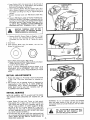
1. Reduce Tire pressure to 14 pounds in frontand 10 pounds
in rear T_res. (Tires were overinflated for shipping purposes),
2, Seat position may be adjusted forward or backward by
_oosening Bolt in Seat Plate (Fig 6) NOTE: WHEN RETiGHTENiNG
BOLT AFTER
ADJUSTMENT,
MAKE
SURE SEAT PLATE HAS NOT TWISTED OUT OF
ALIGNMENT
WITH SEAT SPRING
INITIAL
SERVICE
NOTE:
BE CAREFUL
THE
ENGINE
WHEN
FUEL,
NOT TO ALLOW
CHECKING
OR
DIRT TO ENTER
ADDING
OIL OR
1, Check Engine Oil Level with Tractor on level ground,
Wipe d{pstick (Fig 7) clean, push it in tight for a few sec_
onds, remove and read Oil Level If necessary, add Oil until
"FULL" mark is reached. In summer use S.A E, 30 (SC,
SD, SE or SF) Oil, In winter (below 32°F)
use SA, E.
10W30 (SC, SD, SE or SF). In extreme cold (beJow D°F.)
use S,A.E. 5W20 (SC, SD, SE or SF) DO NOT USE 10W40
OIL. NOTE: DO NOT OVERFILL
2. Fil! Fuel Tank (Fig, 6) with fresh, clean regular grade leaded or !ow-tead automotive gasoline only. Capacity is 3.1/2
gallons. NOTE: DO NOT SWITCH FROM LEADED TO
LEAD-FREE GASOLINE.
-3-
WARNING:
Do not use Gasoholo Gasohol type alcohols
react with water content in the fuel and tend to form
strong acids which can corrode metal parts, even eat rubber
and plastics°
FILL TO BOTTOM OF GAS TANK
ER NECK. DO NOT OVERFILL.
OFF ANY SPILLED OIL OR FUEL.
FILLWIPE
1,,
Keep aIl shields
in place,.
2, Before leaving operator's position:
a Shift transmission to neutral
b Set Parking Brake.
c, Disengage Attachment Lever,
d Shut off engine,
e, Remove Ignition Key,
FIGURE 8
3,
Wait
fm
all
movement
4_ Keep peopie
and
to stop
before
pets a safe distance
servicing
away
from
machine,,
machine.
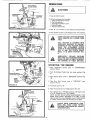
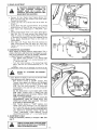
LEARN TO START, STOP AND REVERSE
YOUR TRACTOR
tN A LARGE, OPEN
AREA.
CLUTCH°BRAKE PEDAL
"DRIVE"
POSITION
FOOT , \
PEDAL
THIS TRACTOR
tS EQUIPPED
WITH
INTERLOCK
SWITCHES TO PREVENT
STARTING
OF THE TRACTOR ENGINE
WHILE
THE
ATTACHMENT
CLUTCH
LEVER IS IN THE ENGAGED POSITION
(FIG. 8) AND THE CLUTCH
BRAKE
PEDAL IS IN DRIVE POSITION
(FIG.
9),
|
IMMEDIATELY
REPLACE
SWITCHES
THAT ARE NOT IN PROPER WORKING
ORDER. DO NOT' ATTEMPT TO DEFEAT
THE PURPOSE OF THESE SWITCHES.
STARTUNG
1. Place Attachment
position (Fig_ B),
IGNITION
-_
2. Push Clutch-Brake
KEY
PARKING
ENGINE
Clutch
Lever
Pedal fully
in
"DISENGAGED"
into brake posit{on
(Fig.
9)_
BRAKE
3, Place Parking Brake Lever in "ENGAGED"
"DISENGAGED".
POSITION
GEAR
SHIFT
4, Place Gear Shift
position (Fig 8).
FIGURE 10
_
"
-
6. Move Throttle
II
f
Control
Lever in "NEUTRAL",
start
Control to middle position
(Fig. 10L
7_ Turn Ignition Key to "START" position until Engine starts
(Fig. 10). Release key into "ON" position°
NOTE: DO NOT RUN STARTER CONTINUOUSLY
FOR
MORE THAN THIRTY SECONDS AT A TIMEo tf engine
does not start after several atl:empts, move Throttle Control
to FAST pos_tlon, wmt a few minutes, and try again.
I]"--- "FAST"
'|,
(Fig..
5 Pull Choke out (Fig 10]
VARIDRIVE
CONTROL
LEVER
"SLOW"
POSITION
_ I_'(7 \_
position
t0)
/
LEVER
_t_
THE
II
*
,
,
POSITION
ALWAYS WEAR SUBSTANTIAL
FDOT_
WEAR AND AVOID
LOOSE FITTING
CLOTHING THAT COULD GET CAUGHT
IN MOVING PARTS.
FIGURE
11 _-"_,_-:"
'_"-"i"-_'_
-4-
WARMUNG
UP
THE
ENGINE
Move Throttle Control to "SLOW" position. Push Choke in
as engine warms up. NOTE: ALLOW ENGINE TO WARM UP
FOR A FEW MINUTES BEFORE OPERATING.
When restartinq a warm engine move Throttle Control midway between SLOW and FAST position,, Choke may not
have to be used.
TRACTOR
I
OPERATION
With engine running and warm place Throttle Control midway between SLOW and FAST post on.
Push Clutch-Brake Pedal down flrmly to disengage Parking
Brake and hold Clutch-Brake Pedal in Brake position (Fig,
9)
Move Gear Shift Control Lever to desired gear (Fig. 10).
Release Clutch-Brake
Pedal SLOWLY to start forward
or rearward movement
Move Varidrive Control Lever to desired speed (Fig. 11)
If ground travel is too slow advance Throttle Lever.
NOTE: ALWAYS SELECT A GROUND TRAVEL SPEED
THAT WILL SUIT THE TERRAIN AND THE ATTACHMENT BE{NG USED.
t
2o
3.
4,
5.
II
fl
I_
*
,
2o Move Shift Control Lever to "NEUTRAL" position.
3 Place Parking Brake in "ENGAGED" position:
CLUTCH-BRAKE
PEDAL SHOULD
REMAIN COMPLETELY DEPRESSED WHEN
FOOT PRESSURE IS RELEASED.
DO NOT OPERATE VARIDRIVE
CONTROL UNLESS ENGINE
IS RUNNING.
DAMAGE MAY OCCUR TO VARIDRIVE
SYSTEM.
BRING TRACTOR TO COMPLETE
BEFORE SHIFTING GEARS°
4, Place Attachment Clutch Lever in "DISENGAGED"
tion and Iower attachment to the ground.
It
rl
5. Move Throttle
Control to SLOW I| position.
•
I1
, ,
6. Move Var_drlve Control Lever to SLOW post ono
7o Turn Ignition Key to "OFF" position.
STOP
REMOVE KEY WHEN
TOR
TO PREVENT
USE.
NEVER PLACE YOUR HANDS OR FEET
tN OR UNDER ANY POWERED ATTACHMENT OR NEAR ANY MOVING PART
WHILE TRACTOR OR ANY POWERED
ATTACHMENT IS RUNNING.
DO NOT OPERATE THE MOWER WITHOUT EITHER THE ENTIRE GRASS CATCHER, ON MOWERS SO EQUIPPED, OR
THE DEFLECTOR
SHIELD IN PLACE.
TRANSPORTnNO
TOWING
IS NOT
damage can result°
NOTE: ALWAYS OPERATE ENGINE AT FULL ENGINE
RPM WHEN MOWING TO ASSURE BETTER MOWING PERFORMANCE,
LONG ENGINE LIFE AND PROPER DISCHARGE OF CUT MATERIAL.
ATTACHMENT
LIFT
Due to different
weights
Lift
Spring
may
require
is located on rear of tractor
of Attachments,
the Attachment
adjustment,
The Adjustment
Bolt
top ieft side (Fig° 12),
TRACTOR
Retighten
Jam Nut
DO
against
NOT
SPRING
LIGHT
MOWER.
Spring
ATTACHMENTS,
EXTENSION
1. Push Clutch-Brake
tion.
YOUR
MAXIMUM
WHEN
SUCHUSING
AS
into
"BRAKE
gears BEFORE
starting
up or
Lever
b, If stopping
is absolutely
necessary, push Clutch-Brake
Pedal quickly
to brake position
and lock Parking Brake,
c, To restart
your
tractor,
make
sure tractor
is in 1st
year and that you have allowed
room to roll slightty
downhill,,
Unlock
Parking
Brake
and retease ClutchBrake Pedal SLOWLY
to start tractor
forward
move-
TRACTOR
Pedal completely
ON HILLS
LEAVE ENOUGH ROOM WHEN STOPPING
AND
STARTING
TO ALLOW
SLIGHT TRACTOR ROLL DOWNHILL AS
CLUTCH-BRAKE
PEDAL
MOVES
THROUGH CLUTCH POSITION.
ING
ADJUSTATTACHMENT,
LIFT SPRING TODON'T
AID tN OVER
LIFTPOWER SPRING.
STOPPIINO
transexle
2. AVOID STOPPING OR SHIFTING ON HILLS,,
a, If slowing is necessary, move Varidrive Control
to slower position.
Bushing
FOR
Internal
DO NOT DRIVE UP OR DOWN HILLS
WITH
SLOPES GREATER
THAN
15°,
AND DO NOT DRIVE
ACROSS ANY
SLOPE.
ADJUSTMENT
ADJUST
i
TRACTOR
RECOMMENDED
1 Choose one of the lowest
down hills.
1. Holding Spring Bushing with Wrench, loosen Jam Nut.
2 Turn Adjustment
Bolt clockwise
((_) to extend Spring and
reduce lift effort
(for heavier Attachments),
3, Turn Adjustment
Bolt counterclockwise
( f-_ ) (for Hghter
Attachments),
4,
LEAVING TRACUNAUTHORIZED
YOUR
OPERATION
posi-
3
t' posi-
-5-
ment,
then move Varidrive
speed,
Make all turns gradually
Control
Lever
to
desired
1,, Connect each end of the RED cable to the POSITIVE (+)
terminals of each battery (taking care not to shor_t against
chassis),
2, Connect one end of the BLACK cable to the NEGATIVE
(-) terminal of fully charged battery.
3. Connect the other end of the cable to ENGINE BLOCK
or good CHASSIS GROUND on tractor (away from Gas
Tank or Battery),
4,_ Disconnect cables in reverse order':
a, Engine Block or chassis of tractor_
b_ Negative terminal of fully charged battery_
c. Positive terminals,,
CHARGING
DISCHARGING
1
DO
YOUR
TRACTOR
BATTERYNOTTO USE
START
OTHER
VEHICLES.
FIGURE
-
_
13
•
_.
I
I
•
MAINTENANCE
To keep your tractor running better, longer; perform necessaryservice using the following Maintenance Schedule.
Each time you start your tractor, check your Ammeter (Fig.
13). The needle should move towards the + (charging) mark
indicating the battery is being charged as you operate the
tractor.
DISCONNECT
SPARK PLUG WIRES TO
PREVENT ACCIDENTAL
STARTING
BEFORE MAKING ANY INSPECTION, ADJUSTMENT OR REPAIR (EXCEPT CARBURETOR).
DAILY
MAINTENANCE
Make sure all nuts on bolts are tight and cotter pins are secure.
Observe all safety precautions° Keep Tractor well lubricated
(refer to page 8)_
/
ELECTRICAL
DIAGNOSTIC
MAINTENANCE
TERMINAL
BOX
Your Tractor is equipped with a Tractor Diagnostic Terminal
Box which is used to simplify electrical system diagnosis. The
Iocation of the Diagnostic Terminal Box is shown in Fig. 14.
The Diagnostic Terminal Box provides access to a number of
test points within the electrical system of the tractor.
WHEN USING THE DIAGNOSTIC
TERMINAL BOX - ENGINE TO BE STOPPED
AND IGNITION OFF,
DIAGNOSTIC TERMINAL ADAPTEF
FIGURE 15
STARTING
YOUR
A LOW BATTERY
TRACTOR
WITH
USE
PROPER
CHECKING
THROUGH
AL BOX.
If your Battery
is too tow to
start the engine it should . be
II
II
recharged. If Jumper Cables are used for emergency starting
foilow this procedure: NOTE: YOUR TRACTOR IS EQUIPPED WITH A 12 VOLT NEGATIVE GROUNDED SYSTEM
THE OTHER VEHICLE MUST ALSO BE A 12 VOLT NEGATIVE GROUNDED SYSTEM.
EQUIPMENT
OF DIAGNOSTIC
ELECTRICAL
THE
IN
THE
SYSTEM
TERMIN-
The Diagnostic Terminal Box is designed to accept the Diagnostic Terminal Adapter (optional) (Fig° t5), which is available from Sears (Part No. 677A823)_ If you order the Adapter, also order the Test Procedure Manual (Manual Nor 8441J),
showing diagnostic procedures and components of electrical
circuits°
LEAD-ACID BATTERIES GENERATE EXPLOSIVE GASES. KEEP SPARKS, FLAME,
AND
SMOKING
MATERIALS
AWAY
FROM BATTERIES, ALWAYS WEAR EYE
PROTECTION AROUND BATTERIES.
To perform the testing with the Diagnostic Terminal Box, a
quality multimeter or automotive analyzer is required.
_6-
FIRST
R,H.
HOURS
CLUTCH
IDLER
1_ CHECK BELT ADJUSTMENT
New Belts may stretch after the first few hours of operation
resulting in loss of power.
am With engine running, transmission in neutral, place Varidrive Control Lever in "FAST" position (Fig. 11) and
check if Secondary Belt (Fig. 16 - Inset) rides flush with
outside of Variator Sheave (DO NOT PUSH DOWN ON
CLUTCH PEDAL).
b, If Secondary Belt is riding down in groove of Variator
Sheave adjustment is required,
SIDE OF TRACTOR
FLAT
IDLER
t
--
2. V-BELT ADJUSTMENT
a With engine running,
Transmission in "NEUTRAL"
position, move Varidrive Control Lever to full "FAST"
position (Fig. 11)
b. Shut engine off and loosen Adjustment Nut on Bolt "A"
for Variator Stop Plate (Fig. 16).
c, Start engine and run at idle Speed
d Slowly move Vafidrive Control Lever (Fig. 11) forward
or backward until Secondary Belt is riding flush to
1/16" outside of Variator Sheave (Fig 16 - Inset).
NOTE: DO NOT PUSH DOWN ON CLUTCH PEDAL.
e., Shut engine off holding Varidrive Control Lever in position as described in step d and tighten Adjustment Nut
on Bolt "A" (Fig. 16).,
f, Start engine and move Varidrive Control
Lever to
SLOW
posttlon (F_g. 11). Primary Belt should ride
flush to 1/16" out of Variator Sheave (Fig. 16 - Inset).
g Adjustment is complete when the Secondary Belt rides
in the same position on the Variator Sheave in full
"FAST"
position,
as the Primary Belt does in the
"SLOW" position,
h Re-adjust as needed thereafter
i
f Be t cannot be adjusted as described in step g replace
V-Betts= Refer to Belt Replacement , page 12.
ENGINE _-_
PULLEy_
VARIATOR
STOP_ PLATE _-
I
VARIATOR
_""---_'=====_.
CONTROL ARM_'_
_R
_P_R_IM_AgYBELT
SECONDARY
.....
BELT _ "-_
_
_-
ENGINE OIL
FILL
DIPST'CK
&
\
<
_
<
I< -I_ 7_._
Wm_==_m,=,_m
VmWE6'--
FROM
REAR
OF TRACTOR
L
J
3. CHANGE ENGINE OIL
Changing Oil after the first two hours will help eliminate
break4n residue which might be damaging to your Engine,
NOTE: BE CAREFUL NOT TO ALLOW DIRT TO ENTER
THE ENGINE WHEN CHANGING OIL.
a Drain Oil with Engine warm, Unscrew Oil Drain Plug
(Fig. 18) and catch Oil in a suitable container, Replace
Plug,
b Refill Engine Oil (Fig° 17). In summer use S.AE. 30
(SC, SD, SE or SF) Oil. in winter (below 32°F) use
S,A.E_ 10W30 (SC, SD, SE or SF). In extreme cold
(below 0°F.) use S.A_E 5W20 (SC, SD, SE or SF). DO
NOT USE 10W40 OIL. Refill capacity is 3 pints_ NOTE:
DO NOT OVERFILL,
FIGU F_E 18
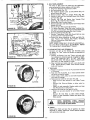
FREGUENTLY
1_ CHECK BATTERY
a Electrolyte solutlon teve] in each Battery Ceil should be
even with bottoms of tubes in cells (Fig. 19)o Add distilled water if necessary NOTE: DO NOT OVERFILL
b, Keep Battery and Terminals clean, Refer to page !2,
step 6.
co Keep Battery Bolts tight.
d. Keep Vent Caps tight and small vent holes in Caps open.
e_ Recharge SLOWLY at 3 amperes if necessary.
CUT-AWAY
-VENTCAP
t'
....................................
........
3
2, CHECK TIRE PRESSURE
Tire pressure in front should be t4 pounds and rear Tires
should be 10 pounds_
3, CLEAN
AIR
TUBE
BATTERY
CELL
SCREEN
Air Screen (Fig,, 17) must be kept free of dirt and chaff
prevent Engine damage from overheating.,
VIEW
to
FIGURE 19
.7-
EVERY
HOURS
1. CHECK ENGINE
OIL LEVEL
DO NOT
WITH
ENGINE
CHECK
RUNNING°
ENGINE
OiL
LEVEL
Several minutes after stopping Engine, check Engine Oil
Level with Tractor on level ground. Wipe dipstick (Fig, 17)
clean, push it down tight for a few seconds, remove and
read Oil Level. If necessary, add Oil until "FULL" mark is
reached.. In summer use S.A,E, 30 (SC, SD, SE or SF) Oil.
In winter (below 32°F.) use S,A.E 10W30 (SC, SD, SE or
SF). In extreme cold (below OAF.) use S.A.E. 5W20 (SC0
SD, SE or SF). DO NOT USE 10W40 OIL. NOTE: DO
NOT OVE RFI LL
fvE.v
(EVERY 15 HOURS IF OPERATING
IN VERY DUSTY CONDITIONS)
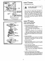
KNOB
CLEAN FOAM PRE-CLEANER.
a_ Unscrew Knob (Fig. 21) to remove Cover.
bo Remove Nut and Washer to remove Cartridge Plate,
Paper Cartridge and Oil Foam Pro-Cleaner,.
c. Wash Foam Pre_31eanerin detergent and water..
d. Rinse, squeeze (rather than twist} and allow to dry
tboroughiy_
e., Coat w_th three tablespoons of S_A.E, 30 Engine Oil,
squeeze to distribute evenly, and squeeze out excess.
f. Check Paper Cartridge. Replace if excessively dirty°
g. Reassemble Paper Cartridge and re-position on Tractor,
NOTE: NEVER RUN ENGINE WITH AIR CLEANER REMOVED.
COVER
_-'-,m--
NUT
WASH ER
CARTRIDGE
PLATE
PAPER
CARTRIDGE
OIL FOAM
PRE.CLEANER
2_
3.
FIGURE_
.o..s
BODY
4,
CLEAN AIR SCREEN
Air Screen (Fig, 22) must allow free-flow of air to prevent
Engine damage from overheating. Clean with a wire brush,
compressed air or water pressure to remove dirt, chaff,
stubborn dried gum and fibers,
CHANGE ENGINE OIL
The best time to change Engine Oil is at the end of a days
operation when all dirt and foreign material is suspended
in the hot Oil. Refer to page 7_
CLEAN FRONT GRILL SCREEN
The Front Grill Screen (Fig_ 2) must allow free flow of air
to prevent engine damage from overheating.
ao Remove Grill Screen by removing two screws.
b. Clean with a wire brush, compressed air or water pres_
sure to remove dirt, chaff, stubborn dried gum and
fibers
c. Replace Grill Screen and secure screws.
5. LUBRICATE STEERING AND FRONT WHEELS
There are seven Grease Fittings on your Tractor (Fig's. 20
and 24)., Using a Grease Gun, give each Grease Fitting two
shots of Extreme Pressure Lubricating Grease Amdex No, 1
or equivalent (available through your Sears Service Center).
-8-
6, OIL PIVOT POINTS
Place several drops of SAA.E. 30 Oil at points where parts
move against each other, especially:
a,, Front Axle Pivot (Fig. 20).
b, Hood Hinges.
c_ Foot Pedal Shaft (Fig_9),
d, Lift Shaft (Fig, 33).
e. Polyfoam Seat at Varlator Arm Assembly Pivot Shaft
(saturate with oil), see page !8, Key No's. 46, 51 and 53.
f. Clutch Link and Varidrlve Control Link, see page 18,
Key No's, 47 and 49,
g Varidrive Handle Pivot Bushing (Fig 33)
HEATSHIELD
HEAT
SHIELD
,AIR
SCREEN
TUBE
VIEWED
FROM
FRONT
FIGURE
22
FIGURE
23
Ew.v B®.o..s
1o CLEAN
ENGINE
COOLING
Remove
any dust.
to prevent
Engine
2. CHECK
a
b
TRANSAXLE
pulted
3. LUBRICATE
c
OIL
Fins
23)
LEVEL
Remove
Filler Plug (Fig, 25) from Transaxle,
Oil Level
should be even with
Filler P}ug threads
Add S A,E 30
Motor Oil if necessary.
Check Pressure Relief Vatve (Fig, 27 - Inset) located on
R,H side near top
It should spring completely
closed
when
a
b
FINS
dirt or oil from
Engine Cooling
damage
from
overheating
(Fig
out by hand
STEERING
and released
U-JOINT
Lift Hood (Fig 2).
Rotate
Steering
Wheel so that
is exposed (Fig 24),
Using a Grease Gun, give Fitting
U-Joint
two
Grease
AND DEBRIS
Fitting
shots of Extreme
Pressure Lubricating
Grease Amdex
No.
(available at your Sears Service Center)
1 or equivalent
4. MUFFLER
Do not operate the tractor without
a Muffler
(Fig. 22) or
tamper
with
the exhaust
system
Damaged
Mufflers
or
spark arresters could create a fire hazard,
Inspect periodlcal{y and replace if necessary
if your engine is equipped
with
a spark arrester screen assembly,
remove
every 50
hours for cleaning and inspection
Replace if damaged.
lvl.v ;]GO.o..s
1,
REPLACE
SPARK
PLUGS
& RESET
GAP
Replace Spark Plugs at the beginning
every 100 hours, whichever
comes first
at .030 inch (Fig. 26)
2o LUBRICATE
BALL JOINTS
a Move Rubber
Boots to expose
and Steering Link (Fig 20)
b. Coat Bait Joints with Silicone
c,
Reposition
Rubber
of each season or
Gap should be set
Ball Joints
Spray
on Tie
Rods
Lubricant.
Boots,
-9-
REPLACE AIR CLEANER PAPER CARTRIDGE
Refer to page 8,_
2oREPLACE IN-LINE FUEL FILTER
If fuel filter is clogged, obstructing fuel flow to carburetor,
reptacement is required,
a, With Engine coot, remove and plug Fuel Line Sections as
removed from both ends of Fuel F_lter (Fig. 28).
b,_Place new Fuel Filter in position in Fuel Line (arrow
on side of Filter in direction of fuel flow)_
LEAKS AND THAT FUEL LINE IS IN
BE
SUREPOSITION
THERE ARE
NO CLAMPS.
FUEL LINE|
PROPER
IN HOSE
J
=w.v 5®@.o..s
1_ CHANGE TRANSAXLE OIL
a_ Block up Rear Axle securely or use a T_to_r Jack_ Re_
move left Rear Wheel by removing Hub Bolts (Fig° 36L
b_ Drain Transa×te Oil by removing Drain Ptug (Fig. 27)
and catching Oil in suitable container. Replace Drain
Plug.
c_ Refill Transaxle with S,,AE_ 30 (SC, SD or SE) Motor
Oil, Capacity is 5 quar"_s_Pressure Relief Valve (R.H. side
of Transaxle)(Fig.
27 _ Inset) may be hefd open to allow
Transaxle to fit! more quick}y.
do Check Pressure Relief Valve.. It should spring completely
closed when pulled out by hand and released.
e, Reposition wheel Secure with Hub Bolts,
AS
NEEDED
1. TOEJN ADJUSTMENT
If any parts in Front Axle or Steering Mechanism are being
replaced, Tie Rod adjustment is required.
a. Loosen Jam Nuts (Fig. 29) at each end of Tie Rod Ad*
justment Sleeves°
b_ Adjust It both Tie Rods so that Tie Rod Joints measure
9 - 5/8 from center to center.
c, On front of front tires measure distance from center to
center (measurement No 1)_
d. On rear of front tires measure distance from center to
center (measurement No 2)..
eo Compare measurements - measurement No. 1 should be
t/8 - 1/4 less than measurement No. 2,
f.. tf not adjust each Tie Rod equally to get correct measurement.
g Tighten Jam Nuts making sure Tie Rod Joints are
parallel (180 °) to each other, This adjustment secures
proper front wheei Toe-In and Steering operation.
FIGURE 29
- 10-
2. BRAKE ADJUSTMENT
IF TRACTOR
REQUIRES MORE THAN
SIX
FEET
STOPPING
DISTANCE
IN
HIGHEST
GEAR ON A LEVEL
DRY
CONCRETE OR PAVED SURFACE THEN
BRAKE MUST BE ADJUSTED+
a
Remove
(4} Hex Washer
Shift Cover Plate (Fig, 30),
Remove the Cover Plate,
Head Tapping
located on top
b
Loosen
Brake
.Jam Nut
(A)
on
Rod
Screws
from
tractor frame+
(B)
at Clevis
(C)
(Fig, 31)
c Rotate
Brake Rod (B) counterclockwise,
(_¢-_) turning
Brake Rod out of Clevis (C) four to six turns (Fig., 31),
•
,
•
rt
I_
*
d, Start
tractor
w_th Transm+ss+on +n NEUTRAL
postion,
eo Depress Brake-Clutch
Pedal to the point where Secondary
Belt (Fig
16) stops moving,
Hold Brake-Clutch
Pedal in position
by engaging
Parking Brake (Fig, 10)
If Secondary
Belt begins to move after engaging Parking
Brake,
depress Brake_CRJtch
Pedal to next notch
on
Parking Brake,
f, Shut engine
off,
Rotate
Brake
Rod (B) clockwise
by
hand, turning
Brake
Rod into Clevis (C), until
tight_
Tighten
,Jam Nut (A) on Brake Rod (B) at Clevis (C)
(Fig, 31)+
3. CARBURETOR
ADJUSTMENT
Never attempt
to change maximum
engine speed This is
preset at the factory
and should only be changed by a qualified service technician
who has the necessary equipment,
a_ Adjust Carburetor
to suggested initial settings.
-- Turn
Needle Valve clockwise
( _
) closing finger
tight ONLY,
and then turn counterclockwise
((_.)
1 - 1/2 turns (Fig 32).
-- Turn
Idie Valve clockwise,
(('_)
closing finger tight
ONLY,
and then turn counterclockwise
(F_)
1 - I/2
turns,
CAUTION:
Valves
may be damaged
REFER TO "STARTING
PAGE 4+
if turned
THE
b- Start Engine and allow to warm for five
final adjustments
with Engine running.
,.+ With Throttle
Control
in "SLOW"
"_
in too far.
ENGINE"
minutes.
Make
position,
hold
Throttle
Lever against Idle Stop and set Idle Speed
Adjusting
Screw
to give an engine speed of 1400
RPM. Turn
Idle Valve clockwise
(('_)
siowly until
engine begins to miss and then open 1/2 turn counterclockwise
(f_)
--
Set Idle Speed Screw
RPM,
When
Throttle
to give engine speed of
Lever is release from
90U
Idle
Stop, engine speed should be between
1000 and 1400
RPM, controlled
by governor
NOTE:
ALL ABOVE
SPEED AND FUEL MIXTURE
ADJUSTMENTS
MUST
BE
DONE
WITH
THE
THROTTLE
LEVER
HELD AGAINST
THE
IDLE
STOP AND AT SPEEDS NOTED,
-. With
Throttte
Contro_
in "FAST"
position,
turn
Needle Valve slowly clockwise
((_)
until engine be+
gins to miss and then set 1/2 turn counterclockwise,
(t'_,)+ NOTE:
IF ENGINE
HESITATESWHEN
MOVING THROTTLE
CONTROL
FROM
+'SLOW"
TO
"FAST"
POSITIONS,
COUNTERCLOCKWISE
4+ ADJUSTMENT
V+BELT
it may be occasionally
page 7).
l
_
TURN
((%)
necessary
NEEDLE
I/8 TURN
to re-adjust
VALVE
MORE
V+Belt_
(See
NOT START
WITHOUT
FU LLY DEPRESSCHECKTOMAKESURETRACTORDOES]
ING
CLUTCH-BRAKE
PEDAL
11-
FIGURE
31
5o
BELT REPLACEMENT
The belts on this tractor
are special
for this application,
when replacing Belts always replace with Sears belts.
a, Disconnect
Negative Ground
Battery Cable_
b. Set Parking Brake (F_g, 10).
c Pull Varidrive
Control
Lever to slow position
(Fig.
11)
giving Primary Belt slack.
d Remove
Primary
Belt from
Engine
Putley
(Fig. 34)_
e,, Remove 3 Bolts and Nuts holding Primary Idler Sheaves
f_
to Frame (Fig. 33).
Remove
Klip
Ring
and Washer from
Shaft (Fig° 34)_ Slide Pivot Arm inwards.
g, Remove
h_ Remove
SHAFT
Primary
Idier
SECONDARY
BELT (REARI
IATOR
S,
BELT KEEPER
ED, YOU MUST CHECK
BELT ADJUSTMENT'.
TO "CHECK
BELT ADJUSTMENTtI0
PAGE 7o
6. CLEAN
BATTERY
AND
REFER
TERMINALS
Corrosion
and dirt on the Battery
and
the Battery to "leak *' power and hinders
PRIMARY
IDL
Terminals
cause
the operation of
the charger,,
a,, Remove
the Battery
from the Tractor
and wash with
four tablespoons
of baking soda to one gallon of water..
NOTE:
BE CAREFUL
NOT
TO GET
THE
SODA
V
FIGURE
Belt from Variator
Sheave.
Idler Nuts and Idler Sheaves from
P_vot
Sheaves (Fig, 34}.
L Primary
(Front)
Belt can now be removed,
j. To replace Secondary
(Rear) Belt move Varidrive
Control Lever to fast position,
Remove Variator
Belt Keeper
(Fig. 34) and remove Secondary
Belt from Variatoro
ko Remove Clutching
Idler (Fig. 34).
I. Remove Transmission
Pulley Belt Guard
Belt can now
be removed from Transmission
Pulley.
m_ Reverse the above procedures
to install new Belts. Replace Primary
Idler
Package,
Belt Keeper,
Clutching
Idler and Transmission
Pulley Belt Guard°
n, Connect Battery,
NOTE:
WHEN A NEW BELT OR BELTS ARE INSTALL-
ENGINE
PIVOT
Variator
34
SOLUTION
INTO THE CELLS,
Rinse the Battery
plain water, dry and reinstall on Tractor_
bo Clean terminals
and cable ends with a wire brush
bright
Replace Battery
tions with Vasoline.
WASH E R
Cables,
7_ TIRE CARE
a,, Maintain
tire pressure in front
WASHER
b
FIGURE
terminal
at 14 pounds
at 10 pounds.
Keep tlres free of gasoline, oil,
cals which can destroy rubber,,
c, Avoid stumps, stones, deep ruts
KLIP
Coat
until
connec-
and rear tires
or insect control
and other
with
chemi-
hazards
that
may cause tire damage,
d. Removing front wheel for tire repair (Fig= 35),,
-- Block up front
axle securely
or use a Sears Tractor
Jack.
.- Remove
Klip Ring and Washer to allow wheel
removal.
.- Repair tire and reassemble.
Replace washer and snap
RiNG
35
Klip Ring securely in axle groove.
e_ Removing rear wheel for tire repair (Fig. 36),
.- Block
up rear axle securely or use a Sears Tractor
Jack.
-- Remove
(5) Hub
Bolts
to allow
wheel
removal.
-- Repair tire and reassemble. Replace and tighten
Hub
Bolts securely_
BOLT
BEADS ARE
SEATED, OVER
WHEN
MOUNTING
TIRES,INFLATION
UNLESS
CAN CAUSE
AN EXPLOSION°
8.
:IGURE
36
FINISH
Keep tractor
finish
and seat free of gasoline, oil, insect
chemicals or battery
electrolyte,_ Protect painted surfaces
with automotive
type wax.
TROUBLE
SH{:)OT|NG
POSSIBLE
CAUSE
WILL
START
NOT
POSSIBLE
Clutch-Brake
Pedal in drive position
Attachment
Clutch Lever in "ENGAGED"
No gasoline in Fuel Tank or clogged Fuel
Line or Fuel Filter
BIown Fuse
Dead Battery
Defective
ignition
or loose Wiring
HARD TO START
Choked improperly,
Push Peda
nto brake position
(Fig, 9)
Move Lever to "DISENGAGED"
position
(Fig_ 8)
Fill Tank with fresh Gasoline, Check Fuel Line (Fig.
28) and Carburetor
(clean if necessary)
Check for fault and replace Fuse
Recharge or replace Battery
Check Wirlng and Spark Plug
position
i
flooded Engine
Place Throttle
Control
in fast position (Fig° t0) and
run starter several times to clear out gas
Remove and clean (Figo 28)
Remove and clean (Fig. 2t)
Clogged Fuel Tank, Fuel Line, or Fue! Filter
Dirty Air Cleaner
Spark Plug dirty or improper
gap
Defective
Battery
Defective
Ignition or loose wiring
Water in gasoline or otd fuel
Replace Spark Plug and adjust gap (Fig_ 26)
Recharge or replace
Check the wiring and Spark Plug
Drain Fuel Tank and Carburetor,
use fresh fuel and
replace Spark Plug
Make necessary adjustments
Improper Carburetor adjustment
ENGINE
MISSES
OR LACKS
Shift
improper
gear or reduce load
(Fig,
28)
Remove and clean (Fig, 21 )
Make necessary adjustments
(Fig. 32)
Clean Air Screen, Cylinder
Fins (Fig,23)
Add or change oil (Fig, 7)
gap or wrong
type
& Muffler
area
Replace Spark Plugs and adjust gap (Fig, 26}
Check Spark Plugs and for any loose wires
Major Engine overhauf
Drain and refit! Gas Tank and Carburetor
OVERHEATS
Dirty Air Screen
Low oil levef or dirty oil
Dirty Engine
Partially plugged Muffler
Part{ally plugged Air Cleaner
Stele fuel or improper Carburetor
Clean Air Screen (Fig,. 17)
Add or change oil (Fig. 7)
Clean Cylinder Fins, rotating Screen and Muffler
Remove and clean Muffler (Fig. 22)
Remove and clean (Fig. 21)
Use fresh fuel and adjust Carburetor (Fig. 32)
adjustment
NO LIGHTS
No Headlight with Light Switch in "ON"
and engine running
WON'T
to a lower
Remove and reptace
Remove and clean
Oit in gasoline
ENGINE
(Fig, 32)
POWER
Engine overload
Clogged Fuel Filter
Clogged Fuel Tank
Partially plugged Air Cleaner
]mproper Carburetor
adjustment
Dirty Air Screen
Low oil level or dirty oil
Spark Plug dirty,
Faulty ignition
Poor compression
REMEDY
position
area
Check Wire Connectlons and Switch,
Replace Light Bulbs
CHARGE
Biown Fuse
Defective
Battery
Check for fault
Replace
and replace
STORAGE
1. ENGINE
Drain
4. BATTERY
a. Remove battery if tractor is not used regularly during
winter months° Store in cool, dry place (above 50°F).
NOTE: DO NOT STORE BATTERY
DIRECTLY
ON
CONCRETE SURFACE.
b. Re-charge each month [f necessary. NOTE: BATTERIES
NOT IN USE FOR SEVERAL
MONTHS AND NOT
KEPT
FULLY
CHARGED,
PRODUCE
SULPHUR
DEPOSITS ON PLATES WHICH CANNOT BE RE.,
MOVED BY RECHARGING.
OIL
(with
engine warm)
and replace
with
clean engine oil-
Refer to page 7.
2. FUEL
a
SYSTEM
Drain fuel tank and carburetor
run out of gasoline,
NOTE:
YOUR ENGINE WILL LEAVE
GING
b.
FUEL
by allowing
the engine to
GASOLINE
LEFT
IN
GUM DEPOSITS
CLOG-
SYSTEM,
D_spose of gasoline if not to be used, NOTE:
GASOLINE
STORED
FOR
SEVERAL
MONTHS
LOSES
ITS VOLATILITY
(ABILITY
TO BURN
EFFECT..
IVELY),
5, GENERAL CLEANING
Clean engine, battery,
finish
etc
of all foreign
matter,
3, CYLINDERS
6. STORE IN A CLEAN AND DRY AREA.
a. Remove Spark Plugs,
b, Pour one ounce of oil through
spark plug holes intocylinderso
c,, Turn
ignition
Key to "START
_t position
for a few
seconds to distribute
oito
d.
Replace with
new Spark
Plugs,,
Sears, Roebuck and Co reserves the right to make any changes
in design or improvements
without
imposing any obligation
to install the same upon its items heretofore
manufactured.
-13-
REPAIR
PARTS
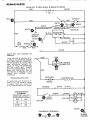
SEARS GTV 16 TWIN--MODEL
RED
NUMBER
917,253724
...................
--
i
+
BLACK
I
12V
-
%
RED
STARTER
%%
WHITE
WHITE
WHITE _r
{iNTER
LOCK SWITCH
OS
IGNITION
SWITCH
ED
0,1(
INTERLOCK
BLACK
MAGNET,
BLACK
BLACK,
RED
_,,
30 a
FUSE
AMMETER
SOLENOID
SWITCH
BLACK
€
PLUGS
0
_
BLACK
G
LIGHTS WILL
AMMETE R
NOT
REGISTER
ON
YOUR TRACTOR
IS EQUIPPED WITH
A SPECIAL
ALTERNATOR
SYSTEM
THE LIGHTS ARE NOT CONNECTED
TO THE BATTERY, BUT HAVE THEIR
OWN
ELECTRICAL
SOURCE.
BECAUSE OF THIS, THE BRIGHTNESS
OF THE
LIGHTS
WILL
CHANGE
WITH THE ENGINE SPEED. AT IDLE
SPEED THE LIGHTS WILL
DIM. AS
THE ENGINE IS SPEEDED UP, THE
LIGHTS
WILL
BECOME
THEIR
BRIGHTEST_
WIRING
INSULATED
C _¸¸
RED
RED
LIFT MOTOR
CONNECTOR
RED
RED
RECTIFIER
CLIPS
CHARGING
COIL
_ .....................
If Insulated
Clips were removed
for seP
vicing
of unit,
they should
be replaced
to properly
secure your
wiring.
There
are four insulated
Clips on your TractoL
(DIODE)
ORANGE
.................
WHITE
¢
IGNITION SWITCH
STD365400
POSITION
BROWN
AC COIL
_k._.....kJ
BROWN
_
BLACK
CIRCUIT
_
OF F
M-G
ON
B-L
START
B-S
LIGHT
SWITCH
YELLOW
YELLOW
BLACK
DIAGNOSTIC
TERMINALS
7
- 14-
CHA,' ;SiS
GROUND
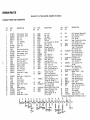
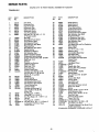
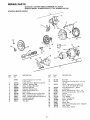
REPASR PARTS
SEARS
GTV
16 TWIN--MODEL
NUMBER
917.253724
ELECTRICAL
A
_-
C
_:_5
D
11
E
22 _
_:_23
19
19.
F
6
47
(_ 48
,_4
D
F
7
31
3
4
tO
24
27
26
45
12
KEY
NO,
1
2
3
4
5
6
PART
NO.
719J
5115J
2008J
STD551125
STD541225
5642P
7
8
9
I0
11
4!71R
51J
4799J
8020J
5584P
12
13
14
7603J
9138R
72240460
15
16
17
18
19
20
21
22
23
24
1507P
STD541625
67187
7661J
7662J
4207J
225J
STD522507
STD551025
2751R
DESCRIPTION
Cover - Terminal
Cable - Starter
Solenoid
*Lockwasher 1/4
*Nut_ Hex Jam 1/4 - 20 UNC
Screw - Hex Hd. Self Tapping
Seres 10 - 24 x 3/8 Type T
Clip - Insulated
Cover - Terminal
Cable - Battery
Harness - ignition & Diagnostic
Screw - Hex Washer Hd, Cutting
1/4 - 20 UNC x 3/4
Tray Battery
Battery
Bott - Rd, Hd, Sq_ Nk.
1/4 - 20 UNC x 7 - 1/2
Washer 9/32 x 3/4 x 16 Ga
*Wing- Nut 1/4- 20 UNC
Rod- Battery
Harness Light
Headlight Bulb
Cable - Battery
Cover- Terminal
*Bolt - Hex Hd 1/4 - 20 UNC x 3/4
*Washer 9/32 x 5/8 x 16 Ga
Clip - Insulated
KEY
NO.
PART
NO.
25
26
27
28
29
30
STD541025
7604J
6999R
1402P
6347R
677A823
DESCRfPTION
*Nut-Hexl/4-20UNC
Tube
- Plastic
Clamp _ Hose
Lockwasher
- 3/8 Ext,
Fuse
Tooth
Diagnostic
Terminal
Adapter
(Optional)
order Test Manual
Key No-31
Test Manual (Optional)
Ammeter
Bracket, Ammeter
Washer 7/32 x 1/2 x 18 Ga.
31
8441J
32
9433R
33
6009J
34
6951J
35
6953J
Nut, No. 10-32
UNF
Loekwasher
No. 10
36
6952J
Switch - Light
37
4482J
Plate - On - Off
38
7682R
Nut- Hex Face
39
7320R
Tie - Cable
40
7192J
41
4406R
Switch - Ignition
Lockwasher
5/8
42
1411P
Nut- Fiat
43
3258J
44
STD365410
Key
Switch - Interlock
45
7755R
Lockwasher
t/4
46
1415P
Bolt - Hex Fin 5/16°
18 x 1/2
47
74760508
Nut- Crownlock
5/1618 UNC
48
73680500
Tag - Warning
--7193J
-8630J
Owners M anual
*STANDARD HARDWARE--PURCHASE
LOCALLY
-15_
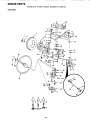
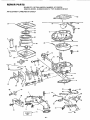
REPAIR
PARTS
SEARS GTV 16 TWIN--MODEL
CHASSIS, FENDER
AND DASHBOARD
NUMBER
917.253724
46
G
7922
G
13
11
44
c_
17
78
27
51
26
|2
30
8O
22
MODEL
36
77
37
36
21
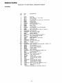
REPAIR
PARTS
SEARS GTV 16 TWIN--MODEL
CHASSIS, FENDER
PART
NO,
DESCRIPTION
KEY
NO.
PART
NO.
1
2
3
4
5
6
7
8
9
!0
11
12
13
14
15
16
t7
18
t9
20
21
677A875
677A432
678H570
678H571
3600J
4110J
677H938
677H937
7091J
677H993
677A876
678H266
678H108
7092J
4904J
7090J
678H614
678H610
678H742
678H33
678H447
Strap
Strap
Bezel
Bezel
33
34
35
36
37
38
39
40
41
42
43
44
45
46
47
48
49
50
5t
52
53
36t6J
4609J
6431J
6999R
5277J
574P
4910J
677H787
678H624
4903J
4902J
1496J
678H609
678H611
4900J
678H267
5592J
1536P
8497J
7651J
5632P
54
55
792IJ
5638P
57
17490616
58
59
545P
STD523707
60
61
62
STD551037
80t9J
563tP
678H340
8022J
7178J
5358J
678H643
80t7J
4182J
677H941
677H786
677H779
677H778
917.253724
AND DASHBOARD
KEY
NO,
22
23
24
25
26
27
28
29
30
31
32
NUMBER
Assembly . Hinge
Assembly - Hinge
• L.H.
- R.H.
Lens - Headlamp
Logo - Grill
Screen - Grill
Grill
Decal - Strip Hood Front
Bracket - Frame, Front
Strap Assembly - Hinge
Brace - Grill - R.H.
Hood
Decal • Strip Hood R.H.
Decat - Strip Hood
Decat - Strip Hood L.H.
Support. Battery
Panel - Side R.H.
Rail • Frame R.H.
Foot Rest- R.H.
Bracket Ass'y. - Hanger.
Front
Bracket Ass'v. - Hanger. Rear
Plug - Dash
Decal, Caution
Decat - Feature
Bracket Lever, Control
Dash
Sleeve _Steering
Cover. Shift - Gate
Fender
Spring -Sea_t
Bracket Ass y. - Fender
A
B
C
D
E
®50
F
G
H
DESCRIPTION
Tank - Fuel
Cap - Fuel
Pad - Spacer
Clamp - Hose
Fuel Line
Nut * Crowntock 1/4 - 20 UNC
Decal - Caution
Foot Rest- L.H.
Drawbar Assembly
Decal - Reflector R.H.
Deca_ -,Reflector L,H,
Seat
Rail • Frame L.H.
Panel - Side L.H.
Decal Clutch/Brake
Brace - Grill L.H.
Guard Belt, Main Dr.
Washer 9/32 x 1/2 x 16 Ga.
Decal - fnstruction
Decat - Control - Vandnve
Screw - Cross Recess Pan Hd.
No. 8 * 18 Hi - Lo x 1/2
Fastener - Push On
Screw - Hax Slotted Hdo
Parkerized Self Tapping Type
AB No. 12x 1/2
Screw - Hex Washer Hd. Thd_
Rolling 3/8 * 16 UNC x 1
Nut - Crownlock 3/8 - I6 UNC
* Bolt - Hex, Finished
3/8 - t6 UNC x 3/4
*Washer 13/32 x 13/16 x 16 Ga,
Washer 7/32 x 5/8 x 16 Ga.
Screw - Finished Hex
Washer Head No. 13 - 16
Hi - Lo x 5/8
J
L
M
N
P
Q
KEY
NO.
PART
NO.
63
67P
64
575P
65
3419P
66
67
7605J
5627P
68
STD533707
69
5514P
70
71
STD551143
3034P
72
73680700
73
STD525010
74
75
STD551150
1625P
76
77
78
79
80
81
3039P
5224J
8023J
678H729
6553J
28P
DESCRIPTION
Bolt . Round Hd. Square Neck
5/16 - 18 UNC x 3/4 Gr. 5
Nut - Crownlock
5/16 - 18 UNC
Screw - Truss H d. C ross Recess
5/16 - 18 UNC x 3/4
Boil - Shoulder 1/4 - 20 UNC
Screw - Hex Washer Hdo
Type TT Thread Rolling
3/8 - 16 UNC x 3/4
*Bolt - Rd, Hd, Sq, Nk.
3/8- 16 UNC x 3/4 Gr, 5
Screw - Hex Washer Hd.
Tapping 1/4- 20 x 1/2
* Lockwasher 7/16
Bolt- Hex, Finished
7/16- 14 UNC x 1
Nut - Crownlock 7/16 !4 UNC
* Bolt - Hex Finished
1/2-13UNCx
1Gr, 5
* Lockwasher 1/2
Washer 17/32 x t - 3/16 x
12 Ga,
BoltHex Finished
7/1614 UNC x 2- 1/2
Safety Standard
Sticker
Labef - Feature, Product
Plate - Cover
Keeper • Belt, Secondary
Bolt - Rd. Hal, Short Sq, Nk,
3/816x 1Gr. 5
ClipFuel Line
Clip Insutated
Decal - Shift Plate
Washer 13/32 x 1 x 14 Ga.
2751R
82
4171R
83
5339J
84
19131614
85
*STANDARD HARDWARE--PURCHASE
R
S
T
@60
58
@ 75
70
LOCALLY
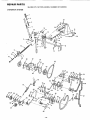
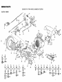
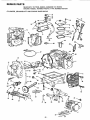
REPAIR
PARTS
SEARS GTV 16 TWIN--MODEL
VARIDRIVE
NUMBER
917.253724
SYSTEM
23
48
4
B
¥
74
19
17 18
13
14
14
69
68
67
13
25
63
65
64
26 27
33 28
66
84
47
28
26 t8
59
39
60 18
45
88
18 -
REPAIR
PARTS
SEARS GTV 16 TWIN--MODEL
VARIDRIVE
KEY
NO
1
2
3
4
5
NUMBER
SYSTEM
PART
NO,
DESC RtPTION
2895H
8016J
2876H
678H642
4551P
Grip - Handle
PlungerLever,
Spring
Lever Assembly
Set Screw - Hex
3/8 - 16 UNC x
Key - Woodruff
LinkLift, LH.
6
7
8
g
10
11
12
13
14
15
16
17
18
19
20
21
22
23
24
25
26
27
28
29
30
31
32
8330H
7596J
STD541037
7594J
5024P
1615P
678H621
I616P
5142H
8488J
4939M
6533J
STD551037
7222J
2876H
STD541237
678H450
gO38R
678H612
7195J
545P
1637P
5315J
7021J
1624P
2263R
28P
33
34
35
36
37
38
39
40
4t
42
43
44
45
46
47
48
678H744
7588J
8001J
4617J
674A271
1588P
5348J
5314J
5661J
1664P
5036P
STD522605
4860J
5986J
5324J
STD560907
Hand
- H and
Socket Forged
3/8 Nylon Patch
1/4 x 1
*Hex Nut3/816 UNC
Bracket- Lift, Loll,
Klip Ring
Washer 15/32 x 13/t6 x 16 GaShaft Assembly o Lift
Washer 29/32 x 1 - 1/4 x 16 Ga.
Pin _ Roll 3/16 x 1 - 1/4
Link - Lift, R.H,,
Pin - Spring, Retaining
Rod- Lift, Adjustment
*Washer 13/32 x 13/16 x 16 Gao
Spacer- Split, 7/t6 x 9/I6 x 3- 1/2
Spring
*Nut- Hex. Jam 3/8- t6 UNC
Trunnion - Adjust. Height
Bearing
Support Assembly - Dash, Steering
Bait Retainer
Nut - Crownlock 3/8 - 16 UNC
Washer 13/32 x t - 1/4 x 12 Ga,
Disc- Friction
Plate - Stop, Variator
Washer 3/8 x I - 1/2 x 5 Ga,
Spring Washer
Bolt- Round HdoSq Neck
3/8- 16UNCx
IGr. 5
Bracket - Stop, Variator
Grip - Handle
Lever - Control, Varidrive
Grip - Handle
Shaft Assembly - Lever, Control
Washer 17/32 x 3/4 x 16 Ga
Actuator, Interlock
Bushing- Control, Lever
Arm - Control, Variator
Washer 19/32 x 1 - 3/4 x 16 Ga.
Klip Ring
*Bolt - Hex Fin,, 1/4 - 20 x I/2
Idler- Flat
Seal - Dirt
Link - Control Variator
*Pin - Cotter 3/32 x 3/4
KEY
NO.
PART
NO.
DESCRIPT!ON
49
5O
51
52
53
54
55
56
_
57
58
5640J
677H916
3445J
1527P
5465J
206J
7930J
Link - Clutch
Arm Assembly - Variator
Seat- Felt
Washer 21/32 x 7/8 x 16 Ga,
Seat - Dirt
Washer _Hardened
Sheave - Variator
52._62_ST-7-AS__ly
J _V2elt
59
60
61
62
63
64
65
66
67
68
69
70
7t
72
73
74
75
76
77
78
79
8O
81
82
84
85
86
87
88
89
9O
91
92
93
94
A
B
25
917253724
C
D
@ 20@ 25e 79
E
F
G
H
@ 18 @ 18@ 16
- 19-
1637P
5031P
5641J
- Idler Clutch
Secon_
Washer 13/32 x I - 1/4 x 12 Ga.
Klip Ring
Spring - Idler
V-Belt Pri m__l'._
5256J
5255J
677H917
5253J
4200J
5328J
678H445
678H641
7g01J
73900400
STD523710
STD523707
STD533707
Guide - Belt, Flat Idler
BracketFiat Idler
Bracket - "V" Idler
GuideBelt, "V" Idler
Pulley _ "V" Idler
Bolt- Adjust, Spring, Assist
BracketSpring, Assist
Spring Assembly - Assist, Lift
Shoulder
Bolt
Flanged
Hex Locknut
I/4
- 20
* Bolt - Hex Finished 3/8 - 16 UNC x t
*Bolt - Hex Finished 3/8 - 16 UNC x 3/4
*Bolt- Round Hd. Sq. Neck
3/8- 16 UNC x 3/4 Gro 5
STD511010
*Screw - Hex Fin. No. 10 - 24 x 1
STD541410
*Nut- No. 10- 24
5627P
Screw - Hex Washer Head Thd,
Rolling 3/8- 16 UNC x 3/4
72110614
Bolt - Rd. Hd. Short Sq, Nk.
3/8- I6UNCx1-3/4
Gr, 5
6855M
Grease Fitting
STD533715
*Bolt- Rd Hd. Sq. Nk.
3/8-15UNCx
!-1/2
STD533710
*Bolt- Rd. H& Sqo Neck Carriage
3/8- 16 x 1 Gr, 5
STD523107
*Bolt- Hex Finished
5/t6- 18 x 3/4
575P
Nut - Crownlock 5/16 - t8 UNC
678H740
Bracket Assembly - Variator
5023P
Klip Ring
5025P
Ktip Ring
1676P
Washer 13/32 x 13/16 x 20 Ga,
STD523717
*Bolt - Hex, Finished
3/8- 16 UNC x t - 3/4
STD551 t25 * Lockwasher 1/4
674A232
Keeper - Belt Assembly
• STANDARD HARDWARE--PURCHASE
LOCALLY
J
K
@ 93
87
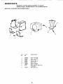
REPAIR
PARTS
SEARS GTV 16 TWIN--MODEL
NUMBER
917.253724
STEERING
1
2
46
48
26
39
26
\
37
\
21
\
.=
43
45
-20-
REPA|R
PARTS
SEARS
GTV
16 TWIN--MODEL
NUMBER
917_253724
STEERING
KEY
NO.
1
2
3
4
5
6
7
8
9
10
t 1
12
13
14
15
16
17
18
19
20
21
23
24
25
26
•-_27
'_
29
30
31
32
33
34
35
37
38
39
40
41
42
43
44
45
46
47
48
49
PART
NO,
DESCRIPTION
5022P
1617P
3641J
9541R
8856M
9040H
678H616
9530R
6266H
6855M
674A244
5298J
3439P
STD551 t62
STD54t062
678H615
5292J
STD523710
545P
677H998
1616P
5293J
STD551137
STD541137
7990J
678H670
Klip Ring
Washer 25/32 x 1 - 1/4x 16Ga
Tire - 16 x 6.50
Front Wheel (Inc. Key No 5 & 2 of Key No. 6)
Grease Fitting
Flanged Bearing
Spindle Assembly, L, Ho
Pin - Groove, 3/16x I - 1/4
Race- Thrust
Fitting - Grease
Axle Assembly - Front (with Bearings)
Tube - Pivot, Axle
Bolt - Hex Fin. 5/8. 11 UNC x 2 - 3/4 Gr, 5
* Lockwasher 5/8
* Nut - Hex 5/8 - t I UNC
Spindle Assembly, RH.
Bushing, Bellcrank
* Bolt - Hex, Finished 3/8 - 16 UNC x 1
Nut- Crownlock 3/8- 16 UNC
Bellcrank Assembly
Washer 29/32 x 1 - I/4 x 16 Ga.
Drag Link
* Lockwasher 3/8
*Nut- Hex 3/8- 24 UNF
Tie Rod
U-Joint Assembly _"
*Screw- Set Hex Forged Socket 3/8 - 16 UNC x t/2
3945J
Pinion * Steering
9858M1
Key - Woodruff 3/16 x 5/8
8839R
Bracket - Support, Steering
6842M
Fitting- Grease
677H997
Sector Assembly
STD523707 * Bolt .. Hex Finished 3/8 - 16 UNC x 3/4
8017P
E - Ring Truarc 5133 - 87
6784J
Wheel - Steering
STD541350
*Nut- Hex .Jam t/2 - 20 UNF
3649J
Insert • Wheel, Steering
677H992
Bracket- Axle
8922R
Tie Rod .Joint L.Ho Thread
547P
Nut Hex Jam 3/8 - 24 UN F
7919J
Tie Rod
STD541337
*Nut Hex Jam 3/8 - 24 UNF
8921R
Tie Rod Joint R.H. Thread
1545P
Washer 17/32 x 1 x t6 Ga,
STD523720
* Bolt- Hex Fin, 3/8- 16 UNC x 2 Gr. 5
518P
Nut- Keps 3/8- 16 UNC
1309H
Bearing
• STANDARD HARDWARE.-PURCHASE
LOCALLY
-21 -
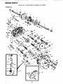
REPAIR PARTS
SEARS GTV 16 TWIN--MODEL
NUMBER
917.253724
2O
°69
B
41
19
34
44 45
55
57
27
T
51
75
\
73
5
33
T
71
74
U
V
W
REPAIR
PARTS
SEARS GTV 16 TWIN--MODEL
NUMBER
917.253724
CLUTCH-BRAKE
KEY
NO.
2
3
4
5
6
7
10
11
12
t_
13
14
15
16
17
18
19
20
21
22
23
24
25
26
27
28
29
30
PART
NO,
1660P
7976J
8545J
9858M 1
61159
74570412
DESCRIPTION
Washer 13/32 x 3/4 x 10 Ga.
M uffl er
Gasket - Muffler
Woodruff Key
Knob - Throttle Control
Screw Hex Socket Hd. 1/4 - 20
x 3/4
678H607
Shield - Heat
STD533707
*Bolt- Round Hd. Short
Sq. Neck 3/8 - 16 UNC x 3/4
Gr. 5
545P
Nut - Crowntock
3/8- 16 UNC
STD551143 * Lockwasher 7/16
STD522503
* Bolt - Hex Finished
1/4 - 20 UNC x 1/2
STD55t 125 * Lockwasher 1/4
574P
Nut- Crownlock
1/4 _ 20 UNC
72140507
Bolt - Rd. Hd. Sq, Neck
5/16 - 18 UNC x 7/8 Gr. 5
STD551037
*Washer 13/32 x 13/16 x
16 Ga.
1402P
Lockwasher 3/B Ext. Tooth
STD541137
*Nut- Fin. Hex 3/8 - 24 UNF
5142H
Pin - Roll 3/16x t - 1/4
678H743
Shaft Assembfv- Pedal,
Foot
8883R
Cover- Pedal. Foot
5304J
Actuator - Switch, Interlock
STD511010
*Screw - Hex Fin. No.
t0-24 UNC x 1
STD541410
*Nut- Lock No. 10 - 24 UNC
STD533107
*Bolt - Rd. Hal. Short Sq. Neck
5/16 - t8 x 3/4 GR. 5
6894J
Control - Choke
3640J
Tire - Rear 23 x 8.50 - 12
795R
Tire Valve
83t8J
Bracket- Interlock Switch
5695J
Control - Throttle
KEY
NO.
PART
NO.
3t
5606P
32
33
34
36
37
38
39
7171J
677H996
7970J
7975J
71673
678H619
3034P
40
41
42
43
1685H
7974J
9396E
1624P
44
45
STD551137
3392P
46
STD5231 I2
47
48
49
5O
51
52
53
54
STD551131
STD54t031
677H918
4033P
4006P
4025P
4001P
STD523707
55
56
7956J
STD523710
57
59
60
61
7955J
9439M
633A109
575P
62
7952J
DESCRIPTION
Screw - Hex Washer Hd.
Thrd. Forming 1/4 - 20 UNC
x 1/2
Bracket - Interlock Switch
Bracket - Support, Steering
Engine - 16 H.P, Twin
Spacer 1 x I - 1/4 x 1.062
Plunger - Cap
Rod - Brake, Parking
Bolt- Fin. Hex
7/16 - t4 UNCx !
Centerlock Nut 5/16 - 18
Pulley - Drive Attachment
Key - 1/4 x 2
Washer 3/8 x 1 - 1/2 x ;
5 Ga,
* Lockwasher • 3/8
Bolt- Hex, Finished
3/8 - 24 UNF x 1 - 3/4
*Bolt- Hex Finished
5/16- 18 UNC x 1 - 1/4 Gr. 5
* Lockwasher 5/16
*Nut- Hex 5/16 - 18 UNC
Base- Engine
Elbow - 1/4 NPT Street
Nipple - 114 NPT x 2_- 1/2
Elbow - t/4 NPT 90 u
Plug- 1/4 NPT Square Head
* Bolt- Hex Finished
3/8 - 16 UNC x 3/4
Adapter - Pulley
*Boll Hex Head 3/8 - 16 UNC
xlGr,
5
Pulley - Ground Drive
Knob - Control
GearShift Lever Ass ' V.
Nut - Crownlock 5/16 18 UNC
Bracket Support, Transaxle
KEY
NO.
PART
NO.
63
64
8021J
73680700
65
66
67
68
5241J
9204H
7424J
STD523107
69
70
71
72
73
74
1599P
9528R
634A692
1304H
7563R
5027P
75
76
77
78
79
80
81
633A110
4t86J
214J
STD560907
2228M
7920J
3!64P
82
3022P
83
11P
84
85
86
87
88
STD541025
677A637
5102J
7229J
511P
89
90
9t
92
93
724tj
5308.1
5101J
100000K
100001 L
*STANDARD
DESCRIPTION
Clip - Insulated
Nut - Crownlock 7/16 14 UNC
Pulley _Transaxle
Locknut, 1/2 20 UNF
Guard - Belt, Transaxle
*Bolt - Hex0 Finished
5/16 - 18 UNC x 3/4 Gr. 5
Washer 11/32 x 3/4 x 16 Ga.
Wheel - Rear
Rear Wheel Hub & Bushing
Bolt- Hub
Washer. Thrust
Klip Ring Truarc
No. 5304-75
Transaxie - 3 Speed
Spacer - Transaxle
Drum - Brake
*Pin - Cotter 3/32 x 3/4
Woodruff Key
Brake Band
Screw- Machine Undercut
Fiat Hd. 3/8 - 16 UNC x 3/4
Bolt - Hex, Finished
3/8 - 16 UNC x 7/8
Bolt - Rd. Hd. Sq. Neck
I/4 - 20 UNC x 5/8 Gr. 5
*Nut. Hex 1/4 - 20 UNC
Bracket Assembly, Brake
Pin - Clevis
Guide - Rod, Brake
Nut - Hex Centeflock with
Nylon
Spring - Compression
Rod - Brake
Clevis
Clamp - Tube, 1 - 1/8
Tube - Exhaust
HARDWARE.-PURCHASE
OPTIONAL
SPARK ARRESTER
LOCALLY
EQUIPMENT
MUFFLER
674A380
REPANR PARTS
SEARS GTV 16 TWIN-MODEL
NUMBER
917.253724
TRANSAXLE
1
2
3
4
23
4
6
7
78
48
32
14
13
64
\
65
76
75
7O
74
70
73
39
70
49
42
92 93
45
25
24
97
- 24
40
REPAIR PARTS
SEARS GTV 16 TWIN--MODEL
NUMBER
917_253724
TRANSAXLE
KEY
NO,
PART
NO,,
I,
2
3
4
5
6
7
8
4t97R
6845R
4199R
4216R
4215R
4217R
6256H
3056P
9
10
12
13
I4
15
16
17
18
19
20
21
22
23
24
25
26
27
28
30
31
7392M
6272H
6266H
4212R
4196R
6276H
216,1
8118M
8740H 1
5385,1
4218R
6252H1
7810H
4986R
7393R
992R 1
6216H
6262H
217J
5855H
633A65
32
33
34
35
36
37
38
39
6277H
4225R
7396H
4198R
4200R
7395H
6275H
633A64
40
41
42
45
46
47
48
48A
4002P
4015P
4014P
6271H
4001P
STD5231t5
1007P
t529R
DESCR IPTtON
Axle Shaft
Retaining Ring
Final Drive Gear
Differential Gear
Differential Pinion
Differential Carrier
Axle Thrust Washer
Hex Bolt 3/8- 24 UNF x 3 - 1/4
(1 "Thread Length}
Steel Ball
Spring-Shift Fork Detent
Thrust Bearing Race
4th Reduction Pinion
3rd Reduction Gear Shaft
Retaining Ring
3rd Reduction gear Spacer
Needle Bearing
Sintered Iron Bearing
3rd Reduction Gear
Differential Pinion Spacer
Differential Pinion Bushing
Gripco Centerlock Nut 3/B - 24 UNF
Shift Fork- L.H_
Oil Seal
Sintered Iron Bearing
Shift Fork Shaft
Shift Fork - R.Ho
Expansion Plug
Pressure Relief Valve
Gearcase and Bearings - R.H.
(Inc. Key No's. 17, 18, 25, 33,
50, 63, 76, 77, and 82)
Dowel Pin
Needle Bearing
Thrust Bearing Race
4th Reduction Gear Shaft
4th Reduction Gear Spacer
Thrust Bearing Race
Gearcase Gasket
Gearcase and Bearings-LH,
(Inc. Key No's,, 18, 25, 49,
50 and, 52)
Pipe Plug 1/2 - 14 N.P,,To
Elbow 90 °, 1/2 - 14 N.PoT.
Std. Pipe Nipple 112 - !4 N,P.To x 3
Oil Seal
Pipe Plug t/4- 18 N, PoT_
"Hex Bolt 5/16.. 18x 1 - 1/2 Grade 5
Lockwasher 5/16 Extra Heavy
Needle Bearing
KEY
NO.
PART
NO.
49
50
52
53
54
55
56
57
58
59
60
62
63
64
4895H
4222R
8119M
4220R
4209R
4213R
5383J
4195R
42t4R
4194R
7528R
4207R
7398H
4203R
65
66
67
68
69
70
71
4204R
2898J
4926H
4205R
4206R
1370H
633A69
72
73
74
75
76
77
78
79
80
81
82
83
54
85
86
87
88
89
90
91
92
93
94
95
96
97
98
4193R
4201R
STD581062
1153R
7392H
5529H
STD541031
1167R
54tP
6270H
7384H
6354H
5384J
2978,1
633A65
8739H 1
4924H
STD551043
8t05R
1569P
75J
6274H
2505P
STD551131
STD52310B
633At09
633At 10
"STANDARD
- 25 -
DESCRIPTION
Needle Bearing
Needle Bearing
Needle Bearing
Thrust Bearing Race
3rd Reduction Pinion
4th Reduction Gear
3rd Reduction Pinion Spacer
2nd Reduction Gear Shaft
Final Drive Pinion
1st Reduction Gear Shaft
1=t Reduction Shaft Spacer
2nd Reduction Gear
Needle Bearing
Low Speed Gear and 2nd Reduction
Pinion Cluster
Reverse Gear
Key Hi-Pro 1/8 x 17/32
Retaining Ring
Intermediate Speed Gear
High Speed Gear
Thrust Bearing Race
Intermediate and High Speed
Cluster Pinion
input Shaft
Low Speed Pinion
"E-Ring
Reverse Idler Gear
Reverse Idler Thrust Washer
Needle Bearing
°Hex Nut 5/16- !8 UNC
Sealing Washer
Hex Jam Nut 7/16- 20 UNF
Oil Seal
Reverse Idler Shaft
Control Knob
Gear Shift Lever
Gear Shift Cap
Gear Shift Ball Cover and pin
Shift Lever Guide
Spring
"Washer t5/32 x 15/16 x 16Gao
Shift Mechanism Seal
Washer 9/16 x 15/16 x 11 Ga.
Gear Shift Gate
Shift Ball Cover Gasket
*Cotter 1/8 x 3/4
°Lockwasher 5/16
°Hex Bolt 5/16 ,,18 UNC x 7/8
Gear Shift Lever Ass'y,
Transaxle Assembly LessBrake Drum
& Sh ft Lever Ass yo
HARDWARE,,-PURCHASE
LOCALLY
REPAIR
PARTS
SEARS GTV 16 'TWIN--MODEL
ENGINE+-MODEL
AIR CLEANER--CARBURETOR
NUMBER
NUMBER
402417,
917_253724
TYPE
NUMBER
0676_01
GROUP
31
10
51
50
65
64
34
6
- 26 -
REPAIR
PARTS
SEARS GTV 16 TWIN-_MODEL
NUMBER
917,253724
ENGINE--MODEL
NUMBER
402417,
TYPE NUMBER
AIR
CLEANER--CARBURETOR
KEY
NO,
PART
NO.
1
2
3
4
5
6
7
8
280185
280198
392970
271412
270884
93414
93208
394338
9
393297
10
11
12
!3
394505
231209
292681
93499
14
15
16
17
18
19
20
21
22
221939
392672
91920
26157
2710G8
298514
230896
299096
394352
23
24
25
222010
392673
93496
27
28
93892
394033
29
30
31
222752
212292
93715
0676-01
GROUP
DESCRIPTION
Tube _ Breather
Tube- intake
Manifold Ass'y. - Intake
+*Gasket _ Carb, Mtg.
*Gasket- Intake Manifold Mtg,
Screw- Carb. Mtg, Sere
Screw- Intake Manifold
Mtg. Sam
I
t
Carburetor Ass y. (Inc_ Key No s. 9
thin 25, 28, 44° 46 thru 51,61, 63,
64 and 65)
Body Ass'y. _Upper Carb, (Inc, Key
No's. 10, 13, 18, 23 and 24)
Body- Upper Carb.
Bushing - Throttle Shaft
+Valve Ass y. - Carb. Idle
Screw - Throttle and Choke Valve
Mtgo Sam
Valve - Throttle
Shaft and Lever - Throttle
Screw _ Mach. Fil. Hd, 8 - 32 x 5/8
Spring- Throttle Adj.
+'Gasket. Carburetor Body
Float - Carburetor
+Pin ° Float Hinge
+Valve - Fuel Inlet
Body _ Lower Carb. (Inc,. Key No_s.
11, 13, 14, 15 and 63)
Valve- Choke
Shaft and Lever - Cl_oke
Screw- Hex Head Sam
10/32 x 5/8
Screw - Sere
+Valve Assembly _ Needle (Inc. Key
No. 44)
Body- Air Cleaner
Knob - Air Cleaner
Nut- Hex
KEY
NOt
PART
NO,
32
33
34
35
36
37
38
39
261444
261531
261446
261563
222807
222828
394324
393346
40
41
42
43
44
45
46
47
48
49
50
51
52
53
54
55
56
57
58
59
60
222289
93868
221535
93893
65978
66432
280197
261395
270988
221377
222615
93829
271271
271411
271180
93853
92278
223001
222835
93496
392643
61
62
63
64
65
67
68
69
70
71
-----
261358
394018
271013
270989
27 t025
93897
394358
299146
93053
394501
393397
394502
DESCRIPTION
Link _,Governor
Link - Speed Control
Spring - Governor
Spring - Governed Idle
Bracket - Speed Control
Lever - Speed Control
Plate Ass'y_ Governor Control
Lever Ass'y. - Governor (Inc. Key
Noes. 40, 55 and 56)
Washer
Screw - Sam
Clamp - Casing
Screw - Sam
+Packing - Needle Valve
Washer - Plain
Body-. Pump
tSpring - Pump
t Diaphragm
1"Cap - Spring
Cover - Diaphragm
Screw - Diaphragm Cover
Element - Air Cleaner
+Gasket- Air Cleaner
Washer
Bolt- Governor Lever
Nut., Hex 10- 24
Cover - Air Cleaner .
Cartridge Plate., Air Cleaner
Screw- Sere
Mounting Strap Assay_- Air Cleaner
(Inc. Key No, 43)
¢Spring
Cartridge ..Air Cleaner
+Washer- (_oke Shaft
t Diaphragm -, Damping
1Gasket - Carb, Pump
Screw - Casing Clamp
FiJter. Fuel (In FueJ Pipe)
Line_ Fuel (28")
Clamp - Fuel Pipe
Gasket Set
Repair Kit - Pump
Carburetor Overhaul Kit
*INC. IN GASKET SET - 394501
+tNC. IN CARBURETOR OVERHAUL
KIT - 394502
1*INCLUDED tN CARBURETOR
OVERHAUL KIT- 394502 &
PUMP REPAIR KIT-393397
- 27 -
REPAIR
PARTS
SEARS G'TV 16 TWIN--MODEL
NUMBER 917.253724
ENGINEJ=MODEL
NUMBER 402417, TYPE NUMBER
CYLINDER,
CRANKSHAFT
AND ENGINE
0676-01
BASE GROUP
69
21
44
16
56
17
59
31
29
27
- 28
REPAIR
PARTS
SEARS GTV 16 TWIN--MODEL
NUMBER
917.253724
ENGINE--MODEL
NUMBER
402417,
TYPE NUMBER
CYLINDER,
CRANKSHAFT
KEY
NOo
PART
NQ
1
2
3
4
5
6
7
8
9
10
11
11
11
12
13
14
15
16
17
18
19
394900
391086
212461
212462
270984
270983
393243
393153
27803
93394
270982
271145
271146
93113
93111
91084
392976
394420
291675
93847
394955
19
19
19
20
20
20
20
21
394956
394957
394958
394959
394960
394961
394962
394023
23
299691
23
24
25
26
27
28
29
30
31
32
33
34
391286
394306
222480
92909
390420
65906
26828
221596
292260
93630
261368
212337
AND
ENGINE
BASE
0676-01
GROUP
DESCRIPTION
KEY
NO
PART
NO.
35
36
37
38
39
40
271316
393244
394348
89838
220863
394539
4t
42
43
44
45
46
47
48
49
50
51
52
53
54
55
56
57
58
59
60
61
63
64
65
66
67
68
69
70
71
72
90576
231174
280180
394014
68838
392782
93783
92268
394391
270981
222700
93053
93851
394396
66538
91540
61760
220863
222773
261363
393606
230655
210940
261463
261559
391115
230318
92791
93722
261528
261623
Cylinder Assembly
Sea!- Oil
Head - Cylinder No. t
Head _Cylinder No. 2
*Gasket - Cylinder Head No. 1
*Gasket - Cylinder Head No. 2
Breather Assembly No. 1
Breather Assembly No. 2
*Gasket - Valve Cover
Screw - Sere
*Gasket - Crankcase Cover t/64" Thick
*Gasket- Crankcase Cover .005" Thick
*Gasket- Crankcase Cover .009" Thick
Screw- Cylinder Head (2 .. 15/16'/, long)
Screw ..Cylinder Head (1 - 15/16 long)
Plug. Oil Drain
Crankshaft
Cover Assembly - Crankcase
Seal ..Oil
Screw - Crankcase Cover Mtg. Sem
Piston Assembly - Standard
(lnc,, Key No_s_,20 & 22)
Piston Assembly- .0!0" O.So
Piston Assembly- 020" O.S
Piston Assembly-_030"
O.&
Ring Set - Piston * Standard
Ring Set- Piston- ..010" O.rS.
Ring Set- Piston - _020" O..So
Ring Set- Piston- _030" O.S.
Dipstick and Tube Assembly
(Inc. Key No s. 44.45 & 46)
Pin Assembly - Piston - Standard
(tnc. Key No. 22)
Pin Assembly .. Piston - .005 '10.S
Rod Assembly - Connecting
Dipper - Connecting Rod
Screw. Connecting Rod
Valve - Exhaust
Spring. Intake Valve
Spring- Exhaust Valve
Retainer .. Intake Valve
Rotocoi! - Exhaust
Retainer .r Exhaust Valve Rotocoil
Tappet- Valve
Gear - Cam
- 29 -
DESCRIPTION
Foam Seat - Governor Shaft
Pipe - Fuel (Inc. Key No. 52)
Gear - Governor
Spark Pfug Wrench
Washer - Gov. Crank (inside)
Plug - Spark (Resistor) (2 - 3/8 High
60 M,M.)
Nut-Hex8-32
Terminal
Grommet- Insulator
Cap and Dipstick - Oil Filler
Seal - Filler Tube
Tube- Oil Filler
Screw- Hex Hd.
Washer
Base -.Engine
*Gasket. Engine Base
Baffle - Air
Clamp .. Fuel Pipe
Retainer- E-Ring
Crank - Governor
Elbow - Spark Plug
Key - Pulley
Key- Flywheel
Washer
Washer - Thrust
Gear - Timing
Seal Assay. and Retainer
+Guide - Exhaust Valve
+Seat - Exhaust Valve (Standard)
+Seat. Intake Valve (Standard)
Lower Bushing - Gov.
Wire - Ground
Connector- Fue! Pipe
Washer - Lock Shakeproof
Terminal - Spade
Valve - Intake
+Bearing - Cyclinder
*INC, IN GASKET SET- 394501
+SPECIAL TOOLS REQUIRED TO INSTALL
REPAIR
PARTS
SEARS GTV 16 TWIN--MODEL
NUMBER
917.253724
ENGINE--MODEL
NUMBER
402417,
TYPE NUMBER
MUFFLER,
AIR
GUIDE
AND
HOUSING
KEY
NO,
t
2
3
4
5
6
7
8
GROUP
PART
NO,
DESCRIPTION
222848
222849
93163
392681
93158
222846
222847
93777
Cover- Air Guide
Cover - Air Guide
Screw - Sere
Housing - Blower
Screw - Sem
Shield - Cylinder
Shield - Cylinder
Screw- Hex Hd, (Back Plate
to Cyli nder)
Back Plate Assay,
392934
_30-
0676-01
REPAM
PARTS
SEARS GTV 16 TWIN-MODEL
NUMBER 917.253724
ENGINE-MODEL
NUMBER 402417, TYPE NUMBER
STARTER
MOTOR
0676-01
GROUP
28
21
KEY
NO.
2
3
4
5
6
7
8
9
10
11
12
13
14
PART
NO.
DESCRIPTION
394891
Armature
394970
221798
93381
394988
393362
393456
93621
391362
393474
19203
390837
392744
93933
Group
(lnc-
Key Nots,
2, 3, 4 and 5)
Trigger Coil Ass'y - Magnatron
PART
NO,
DESCRIPTION
15
16
391705
394674
Brush Set
Commutator
Ignition
Terminal
- ignition Cable
Screw - Armature
Mtgo Sere
Armature
Assembly
I
Alternator
Harness Ass y_
•
I
Dtode and Connector
Ass y.
Screw - Sem
Gear - Flywheel
Ring (Ine, Mtg,, Parts)
Stator - Alternator
(Inc. Key No, 7)
PullerFlywheel
(Optional
Armatu re Assembly
Housing Assembly
Thru Bolt
KEY
NO
Equipment)
-31 -
17
393017
18
19
20
21
22
23
24
25
26
27
28
29
30
31
394429
90366
91162
393254
93754
92674
212418
22906
223008
231247
93808
392956
280104
391135
End Cap Ass'y,
(lnc,, Key
Noo 15)
Motor - Starting
(Inc. Key No_s, 12
thru 15, 16, 18, t9, 20, 30 and 31)
Drive End Cap Assay. - Starter
Lockwasher
Screw- Hex Hd. 5/I6 + 18 x I _ 1/2
Kit - Pinion Spring (Inc.
Roll Pin
Screw- Hex Hd.
Fan - Booster
Lock - Flywheel
Nut
ScrewRotating
NutHex
Screw- Sem
Key No. 22)
Flywheel
and Ring Gear Ass=y. - Magneto
Gear - Starter
Clutch
Ass'y,
- Starter
SERVICE
NOTE8
32 -
SERVICE
NOTES
- 33 -
8630J-1.1231
Printed in U,S°A.
GTV 16 TWIN
OWNERS
MANUAL
VARIDRIVE
GARDEN TRACTOR
MODEL NO.
917.253724
The Model Number wilt be found on the Model Plate attached
to the top right side of Drawbar. Always mention the Model
Number' when requesting service or parts for' your Garden
Tractor,
All parts listed herein may be ordered from any SEARS
BUCK AND CO_ retail or catalog store.
WHEN ORDERING
REPAIR
FOLLOWING
INFORMATION:
HOW TO ORDER
REPAIR PARTS
•
@
®
®
THE
THE
THE
THE
PARTS,
ALWAYS
GIVE
ROE-
THE
PART NUMBER
PART DESCRIPTION
MODEL NUMBER
NAME OF MERCHANDISE
If the pa_ts you need are not stocked locally, your order will
be electronically
transmitted to a Sears Repair Parts Distribution Center for "expedited handling".
Sears, Roebuck and Co. Chicago, III. 60684 U,S.A,